

Page 1
The Smoke/Heat Alarm is mounted on the EI 127 & EI 127R.
The EI 127 pattress facilitates installation of bulky wiring and conduits.
The EI 127R has an additional socket for connecting to the R spade termi
nal on the EI161R or EI 166R. This can be used for remote test & hush or
manual call points.
WARNING: This pattress must only be used with one of the above smoke
alarms as per these instructions - otherwise the unit will not comply with
the mandatory safety regulations.
WARNING: First disconnect the mains from the circuit to be used.
1.Choose a mounting position following the siting instructions in the
Smoke/Heat Alarmleaflet. Where the incoming wiring is onthe surface of
the ceiling, the appropriately sized ducting/conduit must be chosen to
mate with the unit. Use a sharp knife to remove material from the selected
knockout, makingsure that there is no gap when mated withducting / conduit. There arethree knockouts – twoonthe sidewall and oneon the rear.
Installation
Pattress Models EI 127 & EI 127R
For use only with EI 140, 141, 144, 145, 146, 161, 161R,
164, 166, 166R Easi-Fit Smoke/Heat Alarms
Professional
®
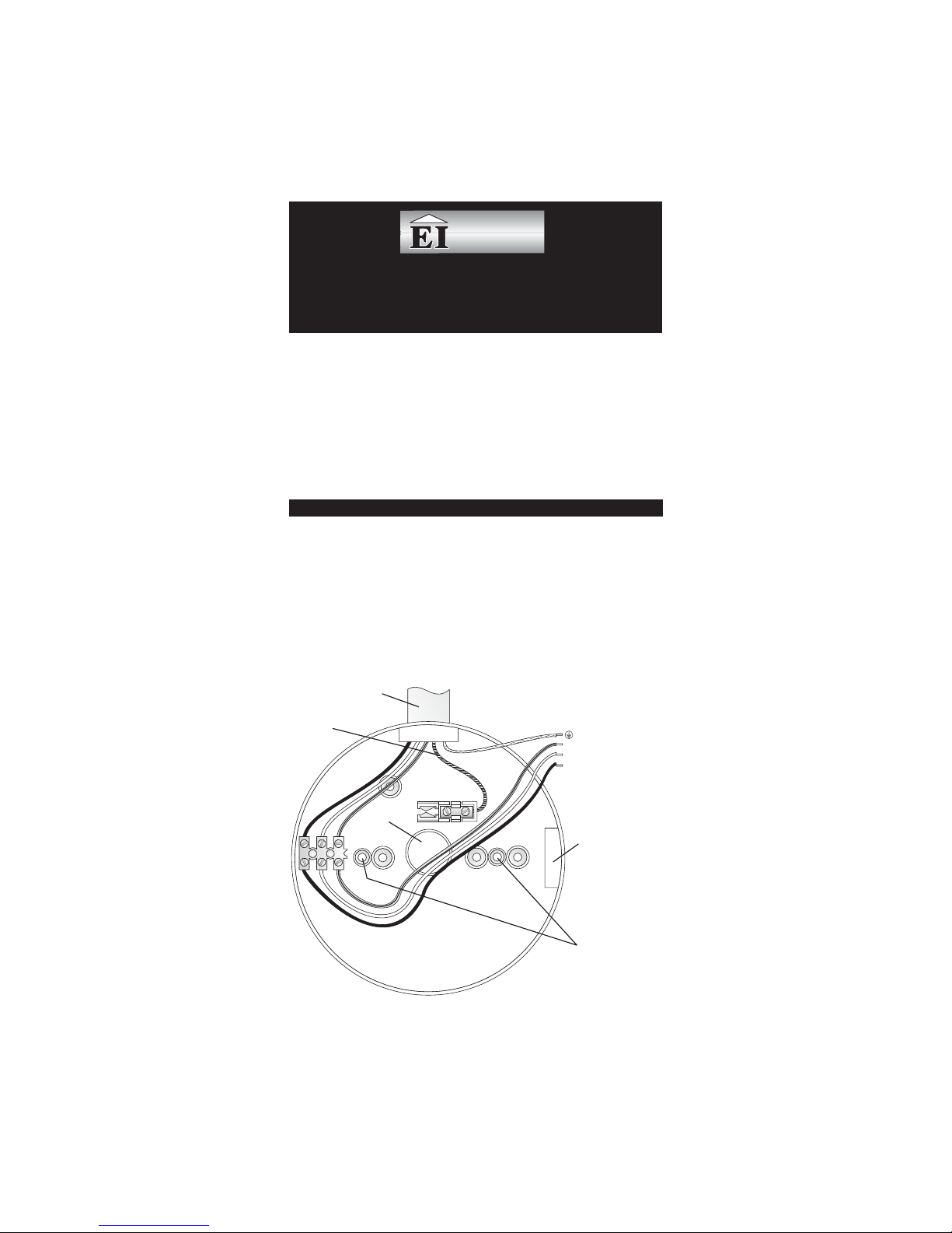
CONDUIT
R
CONNECT TO SMOKE ALARM
MOUNTING PLATE TERMINALS
FOR EI161R/166R
REMOTE CONTROL ONLY
KNOCKOUT
FOR MOUNTING PLATE
N
IC
L
- EARTH (IF PRESENT)
- NEUTRAL
- INTERCONNECT
-LIVE
N
IC
L
KNOCKOUT
Figure 1
Page 2
2.Screw the pattress to the ceiling after first removing the required knock
out and bringing the house wires through it (see figure 1). If the central
knockout is being used, seal around the wires (and the openings at the
rear of thepattress) with siliconeor similar to prevent air draughts affecting
the smoke entering the alarm.
3.Connect the housewires (L - Live,N - Neutral andIC - Interconnect, ifit is
being used) to the terminal block on the pattress. If an EI 161Ror EI 166R
(with remote TEST/HUSH) is being installed, attach the “R” wire from the
EI 152 (see the EI 152 instructions) to the terminal marked “R” in the
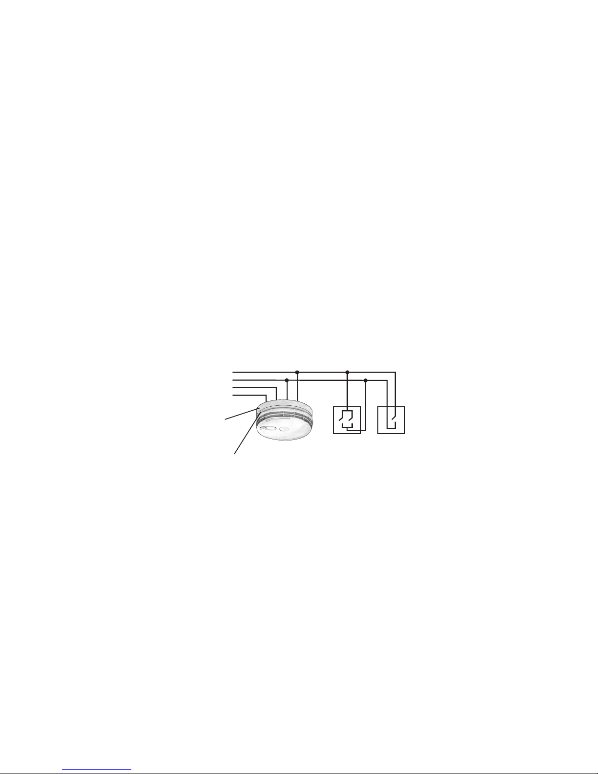
pattress (seefigure 1). If the EI 161R or EI 166R is being used with aman
ual call point MCP400 or MCP400A then connect the R terminal to the call
point (see figures 1& 2). Otherwise do not connect anything to the ”R” ter
minal.
4.Connect the three wires (L, N and IC) from the pattress connector block
to theconnectors on the Smoke/Heat Alarms mounting plate.Connect the
earth wire (if present) from the house wiring directly to the terminal on the
mounting plate. Replace the cover over the terminal wires.
5.Screw the mounting plate to the pattress pillars using the two screws
supplied.
6.Slide the alarm on to the mounting plate.
7.Connect the mains power – the green LED light on the alarm should be
on. When the test button is pressed the horn should sound.
If an EI128R pattress with relayis being used, replacethe EI 127R withthe
EI 128R and follow the instructions supplied with the EI 128R.
Aico Ltd., Mile End Business Park, Maesbury Road, Oswestry,
Shropshire SY10 8NN, U.K.
EI Electronics., Shannon Industrial Estate, Shannon, Co. Clare.
R - Remote
N - Neutral
IC - Interconnect
L - Live
23
Smoke Alarm
EI 161R or EI 166R
EI 152
Manual Call Point
MCP 400
(or MCP 400A)
Pattress
EI 127R/128R
Mounting
Plate
EI 16XR
Figure 2
P/N A13894 Rev 1
 Loading...