

Page 1
RF Modules
for Battery Powered
Smoke & Heat Alarms
EiA600 Series
EiA605MRF Module
Instructions
Read and retain carefully for as long as the product is being used. It contains vital information on the operation and installation
of your Smoke Alarm. The leaflet should be regarded as part of the product.
If you are just installing the unit, the leaftet must be given to the householder. The leaflet is to be given to any subsequent
user.
Page 2

Introduction
Congratulations on purchasing an EiA600 Series RF RadioLINK module. These RF
modules can be easily installed in the EiA600 Series Alarm to provide you with an
RF interconnected fire warning system – when one Alarm senses fire and sounds
a warning, all the other Alarms will also sound a warning. This helps to ensure the
alarm sound will be heard throughout the property.
Installation
1. The EiA600 Series Alarm must be installed as per the guidance in the instruction
booklet ‘Battery Powered Smoke & Heat Alarms’.
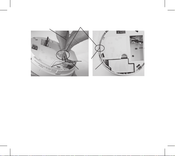
2. Remove the RF module from the packaging and using the pull tag, carefully
insert into the back of the Alarm (see figure 1) - (some Alarm models may have the
RF Module already fitted).
3. Ensure that the battery is connected.
House code the Alarms as follows:
4. Before fitting the Alarm to the mounting plate, press and hold the ‘House Code’
switch on the rear of the RadioLINK module until the red light comes on (see
Figures 2a) and then release.
5. Twist the Alarm onto its mounting plate.
6. Similarly press and hold the House Code switch on the second Alarm until its red
light comes on and then release. Twist the Alarm onto its mounting plate.
Put all the remaining alarms into House Code mode similarly and attach
to the mounting plate in the same manner in less than 15 minutes. (They
automatically exit house code mode after 30 minutes).
2
Page 3
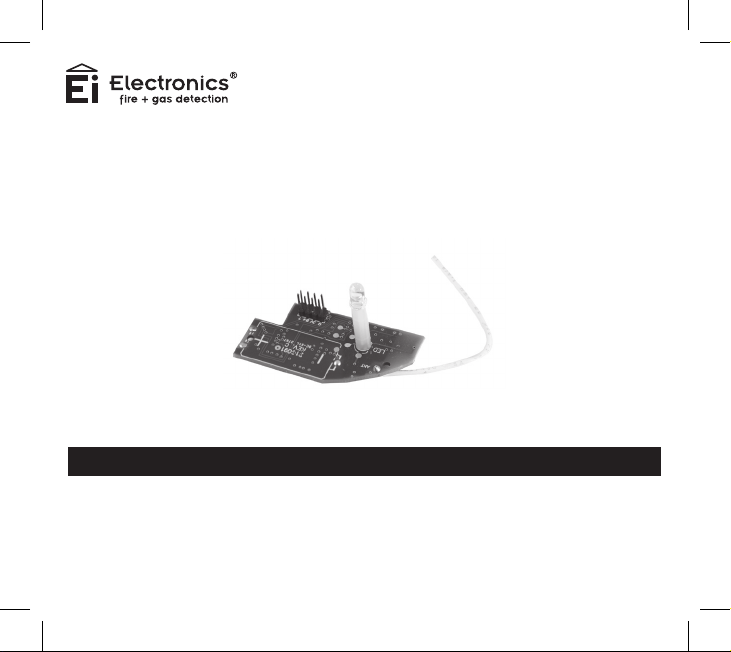
INSERT RF MODULE BY PLUGGING IN PINS & ALSO INSERT ITS
ANTENNA IN THE HOLE PROVIDED - HOLD BY PULL TAG
PULL TAG
ANTENNA
HOLE
LED
ANTENNA
Figure 1
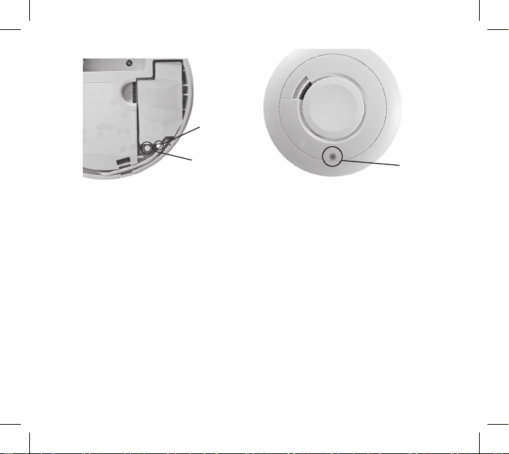
7. When in the House Code mode, the blue light (on the front of the Alarm - see
figure 2b) will flash a number of times every 5 seconds to indicate:
(a) that the Alarm is in House Code mode,
and
(b) the number of Alarms that have been identified and added to your system.
For example with 3 Alarms in your system, you should see 3 blue light flashes every
5 seconds, with 4 Alarms in your system you should see 4 blue light flashes and so
on, (with the 10th unit, the blue flash is longer, to help with the counting).
Check that the number of blue light flashes corresponds to the number of Alarms in
the system. If not see the “RadioLINK Troubleshooting” section below.
3
Page 4
RED LIGHT
Figure 2a
HOUSECODE
SWITCH
Figure 2b
BLUE LIGHT
8. The Alarms will stay in House Code mode for 30 minutes and then reset
automatically. Alternatively they can be taken out of House Code mode by
removing one Alarm from its mounting plate and quickly pressing and holding the
House Code switch until the red light comes on solidly again. Release the switch
and the red light will go out immediately, indicating that the Alarm is no longer in
House Code mode. Replace the Alarm on the mounting plate. The blue light will
no longer be flashing.
Note: As this Alarm exits house code mode it sends a radio message to all the
other Alarms to exit the house code mode. Check that all the blue lights on the rest
of the Alarms have ceased flashing. (Accessories must be taken out of house code
manually - see their instructions).
9. Button test all Alarms in turn and check all the other Alarms are sounding at
the same time. If they are not all communicating see section below “RadioLINK
Troubleshooting”.
4
Page 5

Additional RadioLINK Alarms can be added to the system at any time. Simply put all
the Alarms into the House Code mode at the same time and again check the number
of blue light flashes on each Alarm.
RadioLINK Troubleshooting
It is imperative that all Alarms in your system communicate with each other. The
number of walls, ceilings and metal objects in the signal path reduces the strength of
the RadioLINK signals between the Alarms. Accordingly, one or more Smoke / Heat
Alarms may have difficulties in communicating to all the other Alarms in the system.
If, when checking the RadioLINK interconnection, some of the Alarms do not
respond to the button test, then you will need to either:
(i) Position another RadioLINK Alarm to act as a ‘repeater’ (see Interconnection
with RadioLINK Modules below) between the units which are not communicating
and so shorten the path and/or by-pass an obstacle which is blocking the signal.
When the new Alarm is fitted, house code all Alarms again, as described above.
(ii) For maximum RF signal strength orientate all the antennas in the same direction
- see Figure 3.
(iii) rotate / re-locate the units (e.g. move them away from metal surfaces or wiring).
After making these changes to the RF signal path, the RadioLINK signals may still
not be reaching all the Alarms in your system, even though they have already been
House Coded successfully. (see Section on “RadioLINK Limitations”).
It is important to check that all Alarms are communicating in their final installed
positions. If Alarms are rotated, have had their antennas extended and/or resited,
we would recommend that all the Alarms are returned to the factory settings and
5
Page 6

then House Coded again in their final positions (see above). The RadioLINK
interconnection should then be checked again by button testing all units.
(Note: The RadioLINK module can be returned to the originally factory settings by
pressing and holding the House Code switch on until the red light turns on solidly
and then flashes slowly. This will take about 10 seconds. This clears the House
Codes that have been learnt).
Front Wall Front Wall
Orientate all
mounting plates
in the same
direction
Figure 4
Mounting Plate
Large
hole
nearest
front
wall
Mounting Plate Mounting Plate
Mounting Plate
6
Page 7

Interconnection with RadioLINK Modules
A combined maximum of 18 Alarms (12 Smoke & 6 Heat / CO) with RF RadioLINK
Modules may be interconnected so that if one of the Alarms senses fire, and sounds
a warning, all the other Alarms will also sound a warning. This helps to ensure the
alarm will be heard throughout the property.
As a safety feature, the Alarms as supplied, will all communicate with each other using
the default RF signal. However, to avoid other neighbouring systems setting off your
Alarms and vice versa, we recommend that you “House Code” your Alarm system.
Another very important reason for house coding is that after the Alarms are house
coded, they all act as “repeaters” i.e. they repeat the messages from other Alarms
and so greatly improve the reliability and range of the radio communication.
Note: These Alarms should be interconnected only within the confines of a single
family living residence. If they are connected between different residences there
may be excessive nuisance alarms. Everybody may not be aware that they are
being tested or that it is a nuisance alarm caused by cooking etc.
Depending on the Alarm models you purchased, the RadioLINK module may have
been supplied with the unit or you may have to purchase it separately.
When fitting or removing the RadioLINK module, please hold using the pull tab
attached to it. Also tuck the tab between the Alarm housing and the module when it
is installed in order to avoid it being fouled up with the mounting plate.
7
Page 8

Testing
Your Alarm is a life saving device and should be checked periodically. Regularly
check that the red light on the Alarm flashes approx once a minute to show the units
are powered. Replace the Alarm if the flashing stops.
Manually Testing your Alarms
It is recommended that you test your Alarms after installation and then at least
weekly to ensure the units are working. It will also help you and your family to
become familiar with the sound of the Alarms.
- Press and hold the Test Button until the Alarm sounds and the red light flashes
The Alarm will stop sounding shortly after the button is released.
- If they are interconnected using RadioLINK modules, hold down the Test button until
the blue light on the cover of the Alarm illuminates. Check that all other Alarms sound.
- Release the Test button. The Alarm and all connected Alarms should stop
sounding.
- Repeat this procedure for all other Alarms in the system.
WARNING: Do not test with flame.
8
Page 9

RadioLINK Limitations
Limitations of RadioLINK Radio Frequency Signals
Ei Electronics radio communication systems are very reliable and are tested to high
standards. However, due to their low transmitting power and limited range (required
by regulatory bodies) there are some limitations to be considered:
(i) Receivers may be blocked by radio signals occurring on or near their operating
frequencies, regardless of the House Coding.
(ii) Alarms with RadioLINK modules should be tested regularly, at least weekly.
This is to determine whether there are sources of interference preventing
communication, that the radio paths have not been disrupted by moving furniture
or renovations, and if so, to give a warning of these and other faults.
Changes/modifications to this device not approved by Ei Electronics could void the
user’s authority to operate the equipment.
Getting Your Alarm Serviced
If your Alarm fails to work after you have read the sections on “Installation”, “Testing
and Maintenance” and “Troubleshooting”, then contact Customer Assistance at
the nearest address given at the end of this leaflet. If it needs to be returned for
repair or replacement put it in a padded box with the battery disconnected. Send
it to “Customer Assistance” at the nearest address given on the Alarm or in this
leaflet. State the nature of the fault, where the Alarm was purchased and the date
of purchase.
9
Page 10

Five Year Guarantee
Ei Electronics guarantees this RF RadioLINK module for five years from date of purchase
against any defects that are due to faulty materials or workmanship. This guarantee only
applies to normal conditions of use and service, and does not include damage resulting
from accident, neglect, misuse, unauthorised dismantling, or contamination howsoever
caused. This guarantee excludes incidental and consequential damage. Further the
warranty does not cover Acts of God, such as fire, flood, hurricanes and tornadoes. If this
RF RadioLINK module should become defective within the guarantee period, it must be
returned to Ei Electronics, with proof of purchase, carefully packaged, with the problem
clearly stated. We shall at our discretion repair or replace the faulty unit.
Ei Electronics shall not be liable for any incidental or consequential damages caused by
the breach of any express or implied warranty. Any implied warranty of merchantability or
fitness for purposes is limited to the duration of the above warranty period. This warranty
gives you specific legal rights and you may also have other rights that vary from state
to state.
Some states or jurisdictions do not allow the limitation or exclusion of incidental or
consequential damages, or limitations on how long an implied warranty last so the above
limitation may not apply to you.
Do not interfere with the Alarm or attempt to tamper with it. This will invalidate the
guarantee, but more importantly may expose the user to shock or fire hazards. This
guarantee is in addition to your statutory rights as a consumer.
Ei Electronics makes no warranty, expressed or implied, written or oral, including that of
merchantability or fitness for any particular purpose, with respect to the battery.
The above warranty may not be altered except in writing signed by both parties hereto.
10
Page 11

Technical Specification
Operating Freq: 902.5MHz +/- 20 kHz
Output power: 0dBm
Range: 100m in free air (min)
Protocol: Radiolink
Alarm Transmit Interval: 10 sec
Initial Alarm duration: 3.5 sec
Short Alarm duration: 50 ms
Status Message duration: 50 ms
Weight: 8 grams
FCC Notice:
This device complies with Part 15 of the FCC rules. Operation is subject to the
following two conditions: (1) This devices may not cause harmful interference and
(2) this device must accept any interference received including interference that may
cause undesired operation. FCC ID: A5FEIA605MRF.
11
Page 12

Contact Us
Please return to:
Customer Service
Ei Electronics
Shannon,
Co Clare,
Ireland
Phone: +353 61 471277
Email: sales@eielectronics.ie
Web: www.eielectronics.com
© Ei Electronics 2012
P/N B17445 RevE
 Loading...