

Page 1

Mains Powered
Ei3030 Multi-Sensor Fire
Alarm & Carbon Monoxide
Instruction Manual
Read and retain carefully for as long as the product is being used. It contains vital
information on the operation and installation of your Alarm. The manual should be
regarded as part of the product.
If you are just installing the unit, the manual MUST be given to the householder. The
manual is to be given to any subsequent user.
Page 2
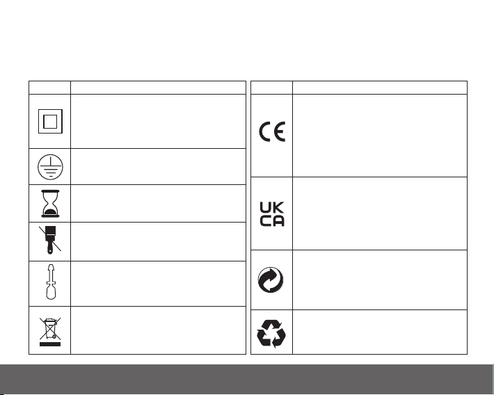
Symbol Glossary
The symbols on this page are used in accordance with EN 62368-1, IEC 60417, ISO 7000 and other
applicable standards. They are used to convey information on the safe and effective use of our devices.
These symbols may be used on the device itself, on its packaging or in associated documentation.
Symbol Description
Class II Equipment
A Class II (class 2) or double insulated
electrical device is designed in such a way
that it does NOT require a safety connection
to electrical earth (ground).
Protective earth
This identifies protective earthing terminals.
End of life
This indicates the date after which the device
should be replaced.
Crossed Paint Brush
This indicates that the device must not be
painted.
Screwdriver
This indicates the location of the releasing
latch used to detach the Alarm from its
mounting plate.
WEEE symbol
Indicates that the device must be taken to a
recycling point when it has reached its end of
life.
Symbol Description
CE mark
This indicates that this product conforms with
the relevant EN standards for products sold
within the European Economic Area (EEA).
The CE marking is also found on products
sold outside the EEA that are manufactured in,
or designed to be sold in, the EEA.
UKCA mark
This indicates that this product conforms with
the relevant standards for products sold within
the United Kingdom (UK). The UKCA marking
is also found on products sold outside the UK
that are designed to be sold in the UK.
The Green Dot
This is a European trademark that indicates
that the manufacturer has contributed
financially to the recycling of packaging in
Europe.
Mobius Loop
This indicates that the packaging of this
product can be recycled.
2
Page 3

Contents
Installer Guide 5
1. Introduction 5
1.1 Overview 7
1.2 Technical Specifications 8
2. Installation 10
2.1 Important Safety Instructions 11
2.2 Where to locate the Alarm? 12
2.3 Where in the room? 16
2.4 Unsuitable locations 18
2.5 Mounting and wiring 19
2.6 Interconnecting Alarms 23
2.7 Removing the Alarm 26
3
Page 4

User Guide 27
3. What is Carbon Monoxide? 27
3.1 Symptoms of CO poisoning 29
3.2 How to protect your family against CO 30
3.3 How does your Alarm work 31
4. Testing 36
4.1 Testing and maintaining your Alarm 37
4.2 Cleaning your Alarm 39
5. What to do in case of Fire alarm 41
6. What to do in case of CO alarm 43
7. Indicator Summary Tables & Troubleshooting 45
8. Limitations of Fire and CO Alarms 54
9. Important safeguards 57
10. Service and Guarantee 59
10.1 Getting your Alarm serviced 60
10.2 Guarantee 60
4
Page 5

Installer Guide
1
Introduction
5
Page 6

The Ei3030 is a Multi-Sensor Fire & Carbon Monoxide Alarm, detecting smoke, heat and carbon
monoxide. It contains a proven optical sensor, with automatic dust compensation, for smouldering
fires, as well as an independent fast acting Class A1 Thermistor sensor to detect dangerous levels
of heat and an electrochemical CO sensor to detect the presence of abnormal levels of Carbon
Monoxide. The combination of Smoke, Heat and CO detection makes it a very versatile Alarm for
most rooms in your house.
Up to 12 Alarms can be interconnected so that if one senses fire and/or CO, all Alarms sound. It can be
a hardwired interconnection, a wireless interconnection or a mixture of both (for the wireless option
an Ei3000MRF SmartLINK module needs to be added to each Alarm – sold separately).
The Ei3000 series is supplied with a mounting plate that allows very quick and simple installation
of the Alarm. The mains and battery power is automatically connected as the Alarm slides onto the
mounting plate.
Each Alarm comes with built-in rechargeable backup batteries to power the Alarm in the event of a
mains failure.
AudioLINK
The Ei3000 series Alarms are AudioLINK+ enabled. This feature allows the user to download
information from the Alarm through the use of a smart phone App. For more information on using
this feature, please refer to the relevant section on www.aico.co.uk.
6
+
Page 7
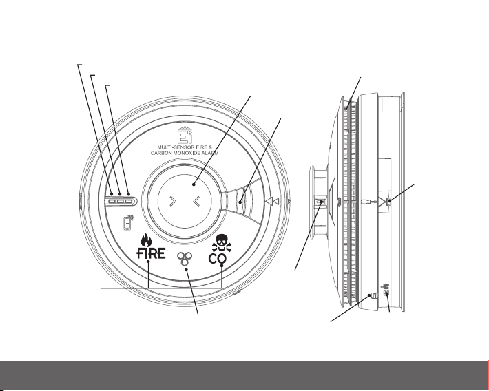
1.1 Overview
Red LED Alarm Indicator
Yellow LED Fault Indicator
Green LED Power Indicator
Test / Hush Button
Alarm Sounder
Smoke Entry Vents
Alarm
Removal
Latch
‘FIRE’ & ‘CO’
LED Display
(normally hidden)
Carbon Monoxide Sensor Entry Holes
Heat Sensor
(Thermistor)
RF Module
LED Indicator
House Code
Button
7
Page 8

1.2 Technical Specifications
Optical Sensor
Heat Sensor
Carbon Monoxide Sensor
Power Supply
Battery Backup
Alarm Sounder
Alarm Sound Level
Memory Feature
Operational Life
Se lf Test
Test/Hush button
AudioLINK
8
+
Optical Photoelectric
Thermistor Class A1 detection – Alarm is triggered at 58°C
Electrochemical
100-250V AC, 50Hz, 0.25W
Built-in 10-year rechargeable Vanadium Pentoxide Lithium cells. Fully
charged, the battery will provide up to 6 months (without module fitted)
or 3 months (with module fitted) back-up without mains power
Piezoelectric Alarm
85dB(A) at 3 meters (min)
Indicates that the Alarm has previously detected fire and or dangerous
levels of CO
10 years
Sensors, battery and electronics are automatically tested periodically
Checks sensors, electronics, display, interconnection and sounder.
If the unit is in alarm when pressed, it silences the alarm for 10min (if
alarming due to heat or smoke), 4 minutes (if alarming due to <150ppm CO)
Enabled
Page 9

Visual indicators
Display
Interconnection
Fixings
Operating & Storage
Temperature
Humidity Range
Plastic Material
Dimensions
Weig ht
Warranty
Approvals
Green LED – Power supply, Test Yellow LED – Fault, EOL
Red LED – memory, pre-alarm or alarm (if coincides with alarm sounding)
Indicates FIRE or CO
Up to 12 units can be interconnected via a hardwired or wireless system
(using optional Ei3000MRF SmartLINK module)
Supplied with Easi-fit anti-tamper mounting plate with integral terminal
block and wiring cover, includes screws and wall plugs
-10°C to +40°C *
15% to 95% RH (non-condensing)
UL94V-0 flame retardant rated
Product: - Ø150mm x 66mm Package - 155 x 155 x 70mm
412g (including packaging)
5 year (limited)
KM86596, KM522831, KM83678,
EN14604:2005+AC 2008, EN50291-1:2018 BS5446-2:2003
* Temperature and Humidity conditions are for normal operation and storage. Units will function outside
these ranges as required by the specific product Standards. Extended exposure to conditions outside
these ranges can reduce product life. For advice on prolonged operation outside these ranges consult
the manufacturer.
9
Page 10

2
Installation
10
Page 11

2.1 Important Safety Instructions
WARNING: Mains operated Alarms must be installed and interconnected by a qualified electrician
in accordance with the local appropriate Regulations for Electrical Installations. Failure to install this
Alarm correctly may expose the user to shock or fire hazards and damage the product.
The Alarm is designed to be permanently mounted, using its own built-in terminal block to connect it
to the mains power supply. The mounting plate can be screwed directly to the ceiling. Alternatively,
it can be screwed to a standard junction box (BS 4662 single gang accessory box). It requires a typical
current of 3mA. The Alarm must not be exposed to dripping or splashing. There are important markings
on the underside of the Alarm.
WARNING: The installation of main operated Heat Alarms should comply with BS 7671.
WARNING: It is a requirement that CO Alarms must be installed by a competent person.
ATTENTION: Alternative Energy Sources - (Wind, Solar, UPS etc.)
This product is designed to be connected to a Pure or True Sine Wave 230V AC supply.
If connecting to a power source that utilises an inverter, e.g. PV solar panel, the Total Harmonic
Distortion (THD) must be less than 5% . If in doubt please check with the manufacturer of the inverter.
This also applies to battery powered UPS (Uninterruptible Power Supply) inverters.
ATTENTION: Light Dimmer Circuits – The Alarms must not be powered from a light dimmer circuit.
ATTENTION: Do not install Alarms in new or renovated buildings until all work is completed.
ATTENTION: The Alarm must not be connected when the house wiring insulation is being checked
with high voltages. i.e. Do not use a high voltage insulation tester on the Alarm.
11
Page 12

ATTENTION: The Alarm must be continuously powered 24 hours a day so it is important that it is
not on a circuit that can be turned off by a switch.
ATTENTION: (UK) BS 5839-6:2019 gives the following recommendations regarding the mains supply
to be used in a Grade D system. The power supply for the Alarms should be derived from the public
electricity supply to the dwelling. The mains supply to the Alarms should take the form of either:
(a) an independent circuit at the dwelling’s main distribution board, in which case no other electrical
equipment should be connected to this circuit (other than a the supply to a dedicated social alarm
control unit); or
(b) a separately electrically protected, regularly used local lighting circuit.
(See BS 5839-6:2019 for further information).
WARNING: An all-pole mains switch shall be incorporated in the electrical installation of the
building.
WARNING: Batteries (battery pack or batteries installed) shall not be exposed to excessive heat such
as sunshine, fire or the like.
2.2 Where to locate the Alarm
Fire Alarms
The Ei3030 contains 3 sensors for smoke, heat and CO detection. It is a versatile Alarm that can be
placed in most rooms of the house, with the exception of a Shower/Bathroom. Care must also be
taken if installing in a kitchen/garage to avoid false alarms due to cooking fumes and contaminants.
A Heat Alarm or combined Heat and CO Alarm may be more suitable for these areas.
The main reason for fitting Multi-Sensor Alarms in dwellings is to ensure that when there is a fire
and/or dangerous levels of CO, sufficient early warning is given so that everybody can escape safely.
This means that the Alarms should ideally be located near all potential sources of fire and CO and that
12
Page 13

the alarm should be heard throughout the house – particularly in the bedrooms.
It is also important that nuisance/false alarms are minimised to ensure the Alarms are not disabled
or ignored.
A single Alarm will give some protection if it is properly installed, but most homes will require two
or more to ensure that a reliable early warning is given. For recommended protection you should put
individual Alarms in all rooms where fire and/or dangerous levels of CO is most likely to break out
(apart from the kitchen and bathroom).
BS 5839-6:2019 gives guidance on:
- how many Alarms to install
- what type of Alarm to use
- where to position Alarms
The above points will depend on the type of dwelling to be protected and the level of fire risk.
Fire Risk Assessment
The ‘Grade’ and ‘Category’ of system that should be installed depends on the fire risk. It is therefore
recommended that a Fire Risk Assessment is undertaken. The Risk Assessment would be based on a
combination of probabilities:
- fire occurring
- injury or death to occupant
- system operating correctly with a fire
- early detection and warning to occupants in the event of a fire
The greater the risks, the more comprehensive and reliable systems needs to be.
13
Page 14

LD (Life protection in Dwellings) Systems define the level of fire protection required for households,
depending on the fire risk and regulations. Aico/Ei Electronics recommends that an LD1 system be
installed for optimum protection.
Please see following pages for detailed information.
CO Alarms
For CO detection, the Ei3030 should be installed in every room containing a fuel burning appliance.
14
Page 15
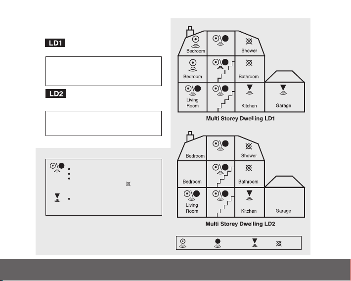
for dwellings where occupants may be at high risk (e.g. elderly)
for new or materially altered dwellings or existing dwellings
with poor structural fire precautions
UK Requirements
Optimum Protection LD1: As LD2, but also including
attics / lofts / other spaces in which a fire might start
(apart from toilets or bathroom).
Interconnect all Alarms
Basic Protection LD2: all circulation areas that form
part of an escaper route within the dwelling, and all high
fire risk areas / rooms e.g. kitchen, living rooms, garages
and all bedrooms (apart from toilets or bathroom).
Interconnect all Alarms
Heat Alarms located in:
(Heat Alarms must be within 5.3m of potential fire
sources)
each Kitchen
Multi-Sensor or Heat Alarms located in:
each Living room (i.e. most frequently used
daytime room)
Multi-Sensor or Smoke Alarms located:
on each storey
every 7.5 m of hallways and escape routes
within 3m of all bedroom doors
(apart from toilets & bathrooms )
BASIC PROTECTION
OPTIMUM PROTECTION
ROI Requirements
OPTIMUM PROTECTION
for dwellings where occupants may be at high risk (e.g. elderly)
Optimum Protection LD1: As LD2, but in addition
Smoke or Heat Alarms should be located in all rooms
and other areas of the dwelling.
(apart from toilets or bathroom)
Interconnect all Alarms
BASIC PROTECTION
for new or materially altered dwellings or existing dwellings
with poor structural fire precautions
Basic Protection LD2: Smoke or Heat Alarms in all
rooms or areas that present a high fire risk to occupants.
(apart from toilets or bathroom)
Interconnect all Alarms
Multi-Sensor or Smoke Alarms located:
on each storey
every 7.5 m of hallways and escape routes
within 3m of all bedroom doors
(apart from toilets & bathrooms )
Heat Alarms located in:
each Kitchen
(Heat Alarms must be within 5.3m of potential fire
sources)
(BS 5839-6:2019)
Multi-Sensor
Fire Alarm
Optical
Smoke Alarm
Heat
Alarm
do not
fit Alarm
15
Page 16
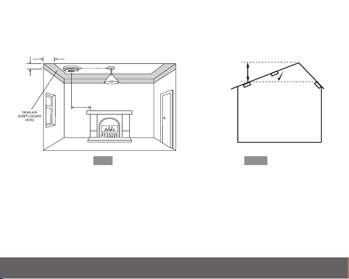
300mm
150mm
1 to 3 m
300mm (min)
<600mm
HEAT ALARMS
<150mm
SMOKE /
MULTI-SENSOR
ALARMS
APEX
xx
2.3 Where in the room?
The locations must comply with applicable building regulations
Fi g.1
- Ceiling Mounting
Hot smoke and gases rise and spread out, so a central ceiling position is the preferred location. The
air is “dead” and does not move in corners, therefore Alarms must be mounted away from corners.
Fit the Alarm:
- At least 300mm away from walls (see Figure 1).
- At least 300mm from any light fitting or decorative object which might obstruct smoke / heat /
Fig.2
CO entering the Alarm.
16
Page 17

- Sloping Ceiling
With a sloping or peaked ceiling, for optimum smoke detection, install the Alarm within 600mm
of the peak (measured vertically). For optimum heat detection, install the Alarm within 150mm.
If the height of the peak is inferior to these measurements, then the ceiling is regarded as being
flat. (see Figure 2).
- In a room WITH a fuel burning appliance
- The Alarm should be at a horizontal distance of between 1m and 3m from the potential CO
source.
- If there is a partition in the room, the Alarm should be located on the same side of the partition
as the potential source.
The Ei3030 is not suited for wall mounting.
17
Page 18

2.4 Unsuitable locations
Do not place the Alarm in any of the following areas:
• In a bathroom or other areas where the Alarm may be exposed to water splashes, dripping or
condensation (e.g. above an electric kettle).
• In very high or awkward areas where it may be difficult to reach the Alarm (for testing, hushing
etc.) or fit the screwdriver to release the Alarm from its mounting plate.
• Next to or directly above heaters or air conditioning vents, doors, windows, extractor fans or
anywhere that it would be affected by draughts.
• Directly above a sink or cooker.
• In an area where the temperature could drop below –10°C or rise above 40°C.
• Outside the building.
• In an enclosed space (e.g. in or below a cupboard).
• In a damp or humid area.
• Where it would be obstructed, e.g. by curtains or furniture.
• Where dirt or dust could block the sensor.
• Near paint, thinners, solvent fumes or air fresheners.
• Locate the Alarm at least 1.5m and route wiring at least 1m away from fluorescent light fittings
as electrical “noise” and/or flickering may affect the Alarm. Do not wire into the same circuit as
fluorescent lights or dimmers.
• Locate the Alarm at least 1m from dimmer controlled lights and wiring as some dimmers can cause
interference.
18
Page 19
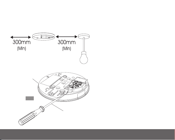
2.5 Mounting and wiring
WARNING: to prevent injury, this apparatus must be securely attached to the ceiling or wall in
accordance with the installation instructions.
1. Select a location complying with the advice
in previous sections.
2. Disconnect the AC mains supply from the
circuit that is going to be used.
3. Lift off the wiring cover as shown in Figure 3.
Foam ceiling gasket
(must be in place)
Fig.3
Insert screwdriver
to lift and remove
wiring cover
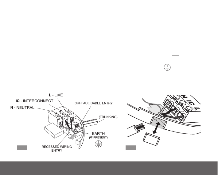
L: Live - connect to the house wires coloured
brown or marked L.
N: Neutral - connect to the house wires
coloured blue or marked N.
IC: Interconnect - see figures 5 and 6 and
further information in Section 2.6.
WARNING: Wiring must be installed in
compliance with local regulations.
19
Page 20
WARNING: Mixing (or poorly terminating) the Live and Neutral connections when interconnecting
Alarms may damage all the Alarms - ensure that the same colours are used throughout the premises
for Live, Neutral and Interconnect wires.
We strongly recommend that you check for the following before connecting the Alarm:
• check for Live and Neutral using a two probe tester.
• check for Live using a neon tester.
• check that the Interconnect wire is NOT connected to Live, Neutral or Earth. Do not use an Earth
wire for the Interconnect line.
Note: The Alarm does not need to be earthed. However the terminal marked is provided for the
convenience of the installer so that any copper Earth wire or cable coloured green and yellow, can
be safely terminated.
REMOVEABLE
TRUNKING DOOR FOR
Fig.4 Fig.5
20
Page 21

To interconnect Alarms connect all the IC terminals together as shown in Figure 8 (see “Interconnecting
Alarms” section).
4. If the mains wires are recessed, bring the wires through the rear hole in the mounting plate as
shown in Figure 4.
If the mains wires are being brought along the surface:
(a) position the mounting plate so the cable trunking is as shown in Figure 4.
(b) the mounting plate has a removable section, take it out to interface directly with 25mm trunking
as shown in Figure 5. If interfacing to 16mm trunking carefully cut around the marked section,
leaving the top intact and replace the section. (If you are not using surface wiring, the removable
section must be left in place for electrical safety reasons).
There are two other positions which are also suitable for the surface wiring to enter (and exit) the
Alarm, one next to the removable section and another directly opposite.
5. Carefully align the mounting plate and screw into place. Connect the wires to the terminal block.
With recessed wiring, ensure the rear gasket seals around the edge of the hole in the ceiling or wall.
This is to prevent air draughts affecting the CO/heat entering the Alarm. If the hole is too large or
the Alarm does not seal it, it should be sealed with silicone rubber or equivalent.
6. Replace the wiring cover and carefully line up the Alarm on the mounting plate and slide on (see
Figure 6).
7. Connect the mains power to the Alarm circuit. Check the green light on the front of the Alarm is on.
8. Press and hold the test/hush button for 10 seconds (see Figure 7). The alarm will sound. Check that
any interconnected Alarms also sound within this period. The test/hush button sounds the local alarm
21
Page 22
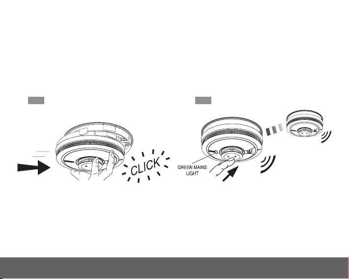
and on release this alarm stops immediately, and all the interconnected Alarms can then be heard in
Slide on the Alarm
Test Alarms
the distance as they will continue to sound for a further 3 seconds. Note: On initial press the Ei3030
will emit the fire sound pattern. On second press the Ei3030 will emit the CO sound pattern.
9. Attach the ’fuse board label’ provided on or near the distribution board and write in date installed
and the number of Alarms on the circuit.
10. Ensure the Alarm operates correctly - see TESTING and MAINTAINING YOUR ALARM section.
Fig.6 Fig.7
22
Page 23

2.6 Interconnecting Alarms
With interconnected Alarms, when one device detects Fire or CO, all will sound. All Alarms will sound
but only Alarms detecting the emergency event will be flashing their red LED alarm indicator.
Any Ei3000 series Alarms can be hardwire interconnected with other Aico mains Alarms such as the
Ei14 0e s eries.
Note: A maximum of 12 devices can be interconnected in an Aico Alarm system.
If you wish to connect more than 12 devices, contact the Aico Technical Department on 01691
664100.
WARNING: Do not hardwire interconnect mains powered Alarms with low voltage or battery
powered Aico Alarms/devices or any other type of Alarm produced by another manufacturer. Doing
so may damage the Alarms and could result in a shock or fire hazard.
Systems using more than 3 or 4 Alarms must be very carefully planned to ensure nuisance alarms are
not excessive. e.g. from cooking fumes or steam. The following is suggested:
• In an RF system an Aico Alarm Controller (Ei450) should be incorporated and be readily accessible
to all occupants so that the source of an alarm can be quickly identified. This is especially
important when both Fire and CO Alarms are used in the same system as the occupant will need
to open all windows and doors if it is a CO incident but do the opposite to slow down a fire.
23
Page 24
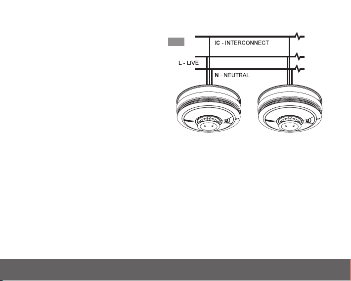
Make electrical connections as shown in Figure 8.
Wiring must be installed in compliance with
local regulations.
Fig.8
In the UK it is recommended that the following
coloured cores are used (for example with
triple flat 6243YH cable).
230V supply : Brown
Neutral: Grey sleeved blue at terminations
Interconnect : Black
The interconnect wire (minimum 0.75mm2
cable) must be treated as if it was Live. It
should be insulated and sheathed.
A maximum of 250 metres of wire can be used (maximum resistance between detectors 50 Ohms).
Alarms should be interconnected only within the confines of a single family living unit. If they are
connected between different units, there may be excessive nuisance alarms. Everybody may not be
aware that they are being tested or that it is a nuisance alarm caused by cooking etc.
The Alarm can also be RF interconnected to other RF Alarms and devices by installing an Ei3000MRF
SmartLINK Module. See the User manual for the Ei3000MRF for further details on RF interconnection.
For maximum RF signal strength, orientate all mounting plates in the same direction to ensure the
antennas of the RF modules are all facing the same way as shown in figure 9.
It is also equipped to work in a hybrid system (combination of hard-wired and RF interconnected
Alarms and devices).
24
Page 25
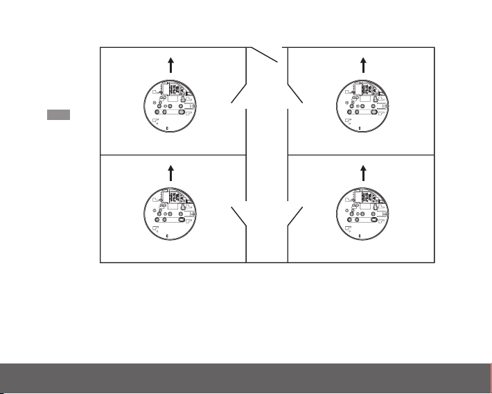
Fig.9
Orientate all
mounting plates
in the same
direction
Front Wall Front Wall
Mounting Plate
Mounting Plate
Mounting Plate
Mounting Plate
Please note in a hybrid system containing Smoke/Heat/CO Alarms we recommend using an Ei3000
Series Alarm as the hybrid link to the RF section of the system.
Ensure the Alarms operate correctly - see TESTING YOUR ALARM in the user section.
25
Page 26
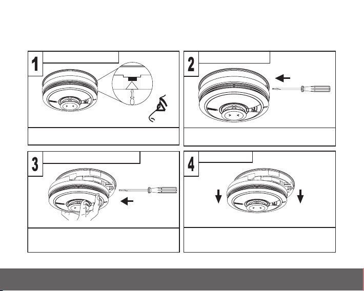
2.7 Removing the Alarm
* Disconnect mains before removal *
Locate removal slot Insert screwdriver
Slide Alarm off mounting plate Remove Alarm
Locate the arrow on the front face of the Alarm
The slot is located directly above the arrow
With the screwdriver still inserted, push the lower
half of the Alarm away from the screwdriver, it the
direction of the arrows on the cover
Hold the lower half of the Alarm and remove from
the mounting plate by lowering the Alarm towards
the floor
Insert a flat-bladed screwdriver horizontally
about 10mm into the centre of the removal slot
26
Page 27

User Guide
What is
Carbon Monoxide?
3
27
Page 28

Many people are killed each year, and many more suffer ill health from Carbon Monoxide (CO)
poisoning. CO is an invisible, odourless, tasteless and extremely toxic gas. It is produced by appliances
and vehicles burning fuels, such as coal, oil, natural/bottled gas, paraffin, wood, petrol, diesel, charcoal
etc. CO is absorbed by red blood cells in the lungs in preference to oxygen - this results in rapid damage
to the heart and brain from oxygen starvation.
High levels of CO in a house can be caused by:
• Incorrectly or poorly installed fuel-burning appliances.
• Blocked or cracked chimneys/flues.
• Blocked vents or draught-proofing which makes areas with fuel burning appliances or fireplaces
airtight.
• Engines of cars, lawnmowers etc. left running in confined spaces.
• Portable paraffin or gas heaters in badly ventilated rooms.
Most people know that high levels of CO are harmful, however the period of exposure is also
important.
A low level for a long period (e.g. 150 ppm for 90 minutes) can cause the same symptoms (a slight
headache) as a high level of CO for a short period (e.g. 350 ppm CO for 30 minutes). Table A shows
how exposure to different concentrations of CO generally affects people.
Many cases of reported Carbon Monoxide poisoning indicate that while victims are aware they are not
well, they become so disorientated they are unable to save themselves by either leaving the building
or calling for assistance. Young children and household pets may be the first affected.
28
Page 29
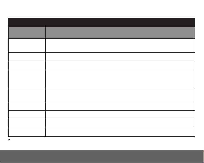
3.1 Symptoms of CO poisoning
Table A
Concentration
of CO in Air ppm
35 The maximum allowable concentration for continuous exposure in any 8
150 Slight headache after 1.5 hours.
200 Slight headache, fatigue, dizziness, nausea after 2-3 hours.
400 Frontal headaches within 1-2 hours, life threatening after 3 hours, also
800 Dizziness, nausea and convulsions within 45 minutes. Unconsciousness
1,600 Headache, dizziness and nausea within 20 minutes. Death within 1 hour.
3,200
6,400
12,800 Death within 1-3 minutes.
ppm = parts per million
*OSHA Occupational Safety and Health Association
Inhalation Time (approx) and Symptoms Developed
hour period according to OSHA *.
maximum parts per million in flue gas (on an air free basis) according to
US Environmental Protection Agency.
within 2 hours. Death within 2-3 hours.
Headache, dizziness and nausea within 5-10 minutes. Death within 25-30 minutes.
Headache, dizziness and nausea within 1-2 minutes. Death within 10-15 minutes.
29
Page 30

3.2 How to protect your family against CO
Follow these guidelines to reduce the risk of Carbon Monoxide poisoning.
(1) Know and look out for tell-tale signs that Carbon Monoxide may be present.
These include:
- The Alarm warning of abnormal levels of CO.
- Staining, sooting or discolouration on or around appliances.
- A pilot light frequently going out.
- A strange smell when an appliance is operating.
- A naked gas flame which is yellow or orange, instead of the normal blue.
- Family members (including pets) exhibiting the “flu-like” symptoms of CO poisoning described
above. If any of these signs are present get the appliance checked out by an expert before further
use. If family members are ill get medical help.
(2) Choose all appliances and vehicles which burn fossil fuels such as coal, oil, natural/bottled gas,
paraffin, wood, petrol, diesel, charcoal etc. with care and have them professionally installed and
regularly maintained.
(3) These appliances must “breathe in” air to burn the fuel properly. Know where the air comes from
and ensure vents/air bricks etc. remain unobstructed (particularly after building work).
(4) The appliances must also “breathe out” the waste gases (including the CO) – usually through a
flue or chimney. Ensure chimneys and flues are not blocked or leaking, and get them checked
every year. Check for excessive rust or cracks on appliances and pipe work.
(5) Never leave your car, motor bike or lawnmower engine running in the garage with the garage
door closed. Never leave the door from the house to the garage open if the car is running.
(6) Never adjust your own gas pilot lights.
30
Page 31

(7) Never use a gas cooker or a barbecue for home heating.
(8) Children should be warned of the dangers of CO poisoning and instructed never to touch, or
interfere with the Alarm. Do not allow small children to press the test/hush button as they could
be subjected to excessive noise when the Alarm sounds.
(9) Leaving windows or doors slightly open (even a few inches) will significantly reduce the risk
of high levels of CO occurring. The high levels of draught-proofing in modern houses reduces
ventilation and can allow dangerous gases to build up.
(10) Install Alarms in all the areas recommended in this booklet.
(11) Recognise that CO poisoning may be the cause when family members suffer from “flu-like”
symptoms when at home but feel better when they are away for extended periods.
IMPORTANT: The Installation of the Alarm should not be used as a substitute for proper installation,
use and maintenance of fuel burning appliances including appropriate ventilation and exhaust
systems.
3.3 How does your Alarm work?
When the Alarm detects Fire and/or abnormal levels of CO, the red LED starts to flash and the alarm will sound.
The Alarm will also trigger all interconnected Alarms to sound, so that the occupier is alerted even if
they are in a different room to the emergency event.
The standard Aico Fire alarm pattern is a continuous rapid pulsing sound type, while the distinctive
Carbon Monoxide alarm pattern is a repeating cycle of 3 slower sound pulses followed by a pause. On
the Ei3030, the LED display will indicate if Fire or CO is detected. The flash rate of the red LED indicator
is dependent on the alarm event type, and in the case of CO, on the level detected. Table B shows how
the CO sensor reacts to different levels of CO gas and exposure time.
31
Page 32
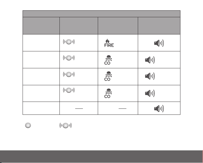
Event type
every sec
every 4 sec
x 4
every 4 sec
x 3
every 4 sec
x 2
x 2
FIRE
Note: The Alarm may sound if cigarette smoke is blown into it, or aerosols are released nearby
CO Gas Level
≥ 50ppm
Red LED
LED icon
Fire or CO
(Ei3028 only)
Alarm
Table B - Alarm indicators
CO Gas Level
≥ 100ppm
CO Gas Level
≥ 300ppm
Alarm triggered by
interconnected Alarm
Flashing
Flashing
within
60-90 mins
within
10-40 mins
within
3 mins
Flashing
Flashing
= LED on solid
= LED flashing
Pre-alarm feature: As soon as the Alarm detects 50ppm or more, the red LED will flash. This helps
locate CO leaks as the Alarm gives an indication straight away.
32
Page 33

Note: In an interconnected system, an Alarm triggered by another Alarm will sound but will not flash
its red LED alarm indicator. This means that while the Alarm is sounding, it is not the unit actually
sensing the alarm event. If you have an Ei1529RC or Ei450 Alarm Controller installed, press the locate
switch to leave just the Alarm that has triggered the system sounding and identify the source and
type of the alarm.
• When fire is detected, you should evacuate the residence, closing all doors and windows along the way.
• If CO is detected, you should open all windows and doors (if safe to do so), and then evacuate.
Once an Alarm detected an event and sounded, the event will be stored in the Alarm‘s memory.
The Alarm memory is an important feature of the Alarm where even if the house is unoccupied during
an alarm condition it warns the homeowner that the Alarm has previously detected Fire or CO gas
and alarmed. It is particularly useful in the case of CO leakages which may have occurred when the
owner is away from the property - for example, CO leaking from a faulty boiler operating on a timer.
The memory feature also helps identify the unit and event type which has previously triggered an
entire alarm system, which can also very helpful after the entire alarm system has gone into alarm
and then stopped, for no obvious reason.
Once the source Alarm has been identified, appropriate action can be taken e.g. In the case of a CO
alarm event in memory, investigate any potential sources of CO leaks. In the case of a fire alarm event
in memory, investigate the cause of nuisance / false alarms by ensuring kitchen or bathroom doors are
kept closed to prevent very hot air or steam from cookers / showers reaching the sensor in the Alarm.
Locate the Alarm further away from the source of steam or condensation and/or replace the Alarm if
it is thought to be defective.
33
Page 34

The memory feature has two operation modes:
- memory indication for 24 hour period after alarm.
- memory recall on demand
24-hour memory indicators: For 24 hours after alarming, the red LED alarm indicator will flash at
different rates every 48 seconds (approx) depending on the alarm event type (Fire or CO) and in the
case of CO, on the level detected - See Memory Mode table in section 7.
Memory recall on demand: To review the memory status at any time, press and hold the test/hush
button, the red LED alarm indicator will flash in accordance to the Memory Mode table (in section 7)
to convey the alarm event in memory, if any.
To Reset the Memory: Hold down the test/hush button for at least 20 seconds. Cover the Alarm with
a cloth to muffle the sound during this time. Clearing of the memory is indicated by a 1-second-long
flash of the red LED alarm indicator. Please note that the Alarm memory will also be reset if the Alarm
is removed from its mounting plate (switched off).
Hush feature
The Alarm has a combined test/hush button. When the alarm sounds, pressing the test/hush button
will immediately silence the alarm for a period of 10 minutes, if due to fire, or 4 minutes, if due to
CO (the red light will continue to flash). After that period of time the Alarm will reset to normal
functionality. In the case of CO, the Alarm can only be silenced once during a CO incident and only
if the CO level detected is < 150ppm.
Note: To stop all Alarms on an interconnected system, press the test/hush button on the Alarm
sensing smoke/heat/CO (i.e. the one with the red LED alarm indicator flashing rapidly) to silence all
Alarms. Pressing the test/hush button on any other Alarm will not cancel the alarm.
34
Page 35

Alternatively, in an interconnected system fitted with a Control switch, you can identify the source
Alarm by pressing the LOCATE switch. When all Alarms are sounding, it will silence all Alarms apart
from the Alarm that is sensing Fire/Smoke/Heat/CO.
If the source of the alarm is due to carbon monoxide, only use the control switch in line of sight of
the CO Alarm to silence it. (Note: The Ei450 can not remotely silence a CO Alarm).
WARNING: If your Carbon Monoxide Alarm sounds (even if you are unsure of the cause), it has
detected dangerous levels of carbon monoxide. Always evacuate the dwelling.
35
Page 36

4
Testing
36
Page 37
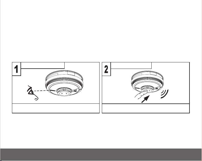
4.1 Testing and maintaining your Alarm
Frequent testing of all your Alarms is a requirement to ensure they are functioning correctly.
Guidelines and best practices for testing are as follows:
1. After the system is installed.
2. Once monthly thereafter.
3. After prolonged absence from the dwelling (e.g. after holiday period).
4. After repair or servicing of any of the systems elements or household electrical works.
Inspecting and Testing proceedure
Check power Test
Check that there is a constant green light
on the cover
Press the test/hush button for 10 seconds.
The Alarm will sound loudly
(i) Check that the green LED power indicator is on continuously.
(ii) Check also that there are no faults i.e. NO green, yellow or red LED flashing (if this is the case please
see indicator summary table).
37
Page 38

(iii) Press the test/hush button for up to 10 seconds and ensure that the Alarm sounds. (Note: On
initial press the Ei3030 will alarm the fire sound pattern. On second press the Ei3030 will alarm the
CO sound pattern). This tests the sensor, electronics and sounder are working. The Alarm will stop
when the button is released. (Refer to indicator summary table if you see Red or Yellow LED flashes).
(iv) Interconnected Alarms only - Test the first unit by pressing the test/hush button for 10 seconds.
All the Alarms should sound within 10 seconds of the first Alarm sounding. After releasing the
test/hush button, the local Alarm will stop sounding immediately and the interconnected Alarms
will be heard sounding in the distance for a further 3-4 seconds. This feature gives an audible
verification that the interconnection is OK. Check all the other Alarms in the same way.
(v) Check the functioning of the mains battery back-up directly after installation and then at least
yearly as follows:
- Turn off the mains power at the distribution board and check that the green indicator light is now
flashing (1 flash every 48 seconds) to indicate the Alarm is on backup battery power.
- Press the test/hush button for up to 10 seconds and ensure the Alarm sounds loudly.
- Monitor the Alarm over a 3 minute period for any fault chirps and or yellow LED fault indicator
flashes (Refer to “Fault Modes” table on what to do if this occurs)
- Turn the mains supply at the distribution board back on.
Switching off Mains for long periods
If the premises are regularly being left without mains power for long periods the Alarms should be
removed from their mounting plates and the Ei3000MRF modules (if fitted) should be removed to
prevent the batteries becoming fully depleted. (This is sometimes done with holiday homes which
are only occupied in the summer).
38
Page 39
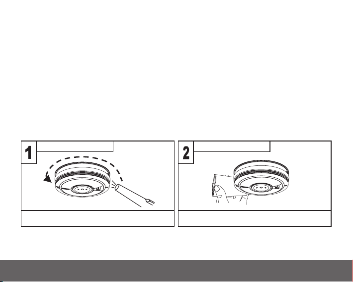
The Ei3000MRF modules (if required) must be re-fitted to the Alarms and the Alarms must be
Vacuum
Vacuum around the side vents to clean
Wipe
Clean the Alarm with a clean damp cloth
and dry thoroughly
re-attached to the mounting plates when the premises are re-occupied. Ensure to match the original
RF module back to the same Alarm head.
(Long term storage (over 1 year) can damage the batteries such that they will not recharge when the
units are re-connected to the mains supply).
DO NOT TEST WITH SMOKE, HEAT OR CO GAS.
We do not recommend testing with smoke, heat or carbon monoxide as the results can be misleading
unless special apparatus is used. However, if testing the Alarm with CO gas is required, the red LED
flashing indicates the presence of CO gas as per table B.
4.2 Cleaning your Alarm
Clean your Alarm regularly. In dusty areas it may be necessary to clean the Alarm more frequently.
Use the narrow nozzle attachment of your vacuum cleaner to remove dust, insects and cobwebs from
the sides and cover slots where the airflow enters. Clean the outside cover by occasionally wiping
39
Page 40

with a clean damp cloth then dry thoroughly with a lint free cloth. Do not use any cleaning agents,
bleaches, detergents or polishes, including those in aerosol cans.
DO NOT PAINT YOUR ALARM.
Other than the cleaning described above, no other customer servicing of this product is required.
Servicing or repairs, when needed, must be performed by the manufacturer.
All Alarms are prone to dust and insect ingress, which can cause false alarms or failure to alarm.
In certain circumstances, even with regular cleaning, contamination can build up in the sensor causing
the Alarm to sound or fail. Contamination is beyond our control, it is totally unpredictable and is
considered normal wear and tear. For this reason, contamination is not covered by the guarantee.
40
Page 41

5
What to do in
case of FIRE?
41
Page 42
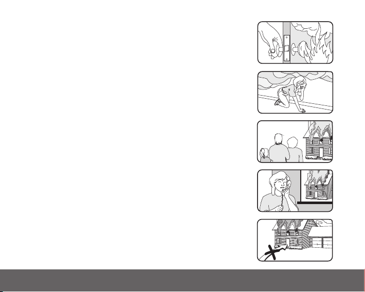
WARNING: If your Alarm sounds and you are unsure of the cause,
it should be assumed that the alarm is due to an actual fire and
the dwelling should be evacuated immediately.
(i). Check room doors for heat or smoke. Do not open a hot door.
Use an alternate escape route. Close all doors behind you as
you leave.
(ii). If smoke is heavy, crawl out, staying close to floor. Take short
breaths, if possible, through a wet cloth or hold your breath.
More people die from smoke inhalation than from flames.
(iii). Get out as fast as you can. Do not stop for packing. Have a
prearranged meeting place outside for all family members.
Check everybody is there.
(iv). Call the Fire Brigade immediately on a mobile phone or from
a neighbour‘s house. Make sure to call the Brigade for all fires
no matter how small - fires can suddenly spread. Also call the
Brigade even if the alarm is automatically transmitted to a
remote manned centre - the link may have failed.
(v). NEVER re-enter a burning house.
42
NEVER
Page 43

6
What to do in case
your Alarm detects
Carbon Monoxide?
43
Page 44

(i) Open the doors and windows to ventilate the area (if it is safe to do so).
(ii) Turn off all fuel appliances where possible.
(iii) Evacuate the property leaving the doors and windows open.
(iv) Get medical help immediately for anyone suffering the effects of Carbon Monoxide poisoning
(headache, nausea), and advise that Carbon Monoxide poisoning is suspected.
(v) Ring your gas or other fuel supplier on their emergency number. Keep the number in a prominent
place.
(vi) Do not re-enter the property until the alarm has stopped. (If the Alarm has been silenced by
pressing the test/hush button, wait at least 5 minutes. The Alarm will then check that the CO
has cleared).
(vii) Do not use the fuel appliances again until they have been checked by an expert. In the case of
gas appliances this must be a Registered Gas Installer.
The alarm will stop once the CO has cleared.
Pressing the test/hush button will silence the alarm immediately for 4min if <150ppm CO. If CO is
still present after 4min, the red LED indicator and alarm will turn on again.
Note: When ventilation is provided by leaving the window and doors open, the CO build up may
have dissipated by the time help arrives and the Alarm may have stopped sounding. Although your
problem may appear temporarily solved, it is crucial that the source of the CO is determined and
appropriate repairs made.
NEVER IGNORE THE ALARM!
44
Page 45

7
Indicator
Summary Tables &
Troubleshooting
45
Page 46
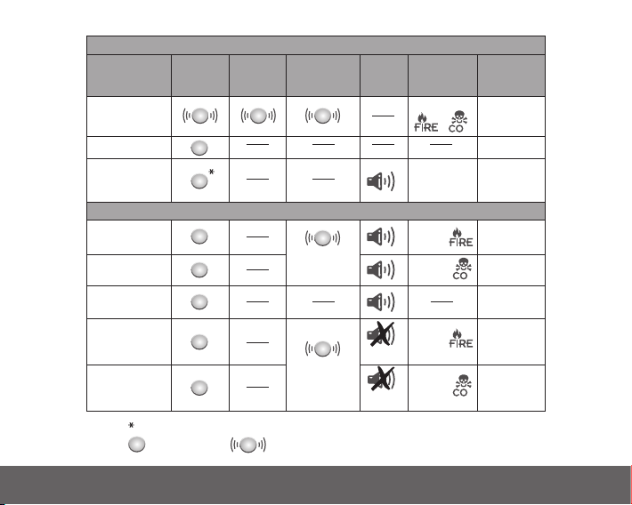
46
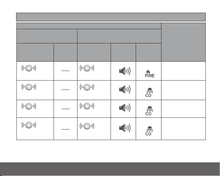
Mode / Action
Power up
Detecting Fire
Activated
via Interconnect
Pressing the
test/hush button
on Alarm
detecting fire
x 10mins
Standby
Testing (pressing
and holding
test/hush button)
Green LED
(Power)
Icon Display
FIRE/CO
(Ei3028 only)
Yellow LED
(Fault)
Red LED
(Alarm)
Alarm Notes
Normal Operation
In Alarm
as per
Table B
as per
Table B
Pressing the
test/hush button
on Alarm
detecting CO
x 4 min if
< 150ppm
1 Flash
Flashing
Flashing
Flashing
Fire sound
pattern
&
Detecting CO
CO sound
pattern
once per
alarm event
Flashing
Flashing
With the test/hush button held the green LED will flicker/pulse every second
= LED on solid
= LED flashing
Page 47
= LED on solid
= LED flashing
Icon Display
FIRE/CO
Red LED
Flashing
Flashing
Flashing
Flashing
What you hear / see
What type of
alarm event
has occurred
x 2
every
8 secs
x 2
every
48 secs
x 4
every
48 secs
x 6
every
48 secs
x 8
every
48 secs
x 4
every
8 secs
x 6
every
8 secs
x 8
every
8 secs
Memory mode
Fire
CO Gas Level
50ppm
CO Gas Level
100ppm
CO Gas Level
300ppm
Alarm memory can be erased by pressing & holding the test/hush button for >20 seconds after
which a 1-second-long flash of the red LED alarm indicator indicates memory cleared
0-24h
>24h
on button test
Sound
Red LED Sound
47
Page 48
every
48 sec
1
every
48 sec
2
every
48 sec
Green LED
(power)
Yellow LED
(fault)
Red LED
(alarm)
What to doWhat it
means
Reconnect AC
mains power
Reconnect AC
mains power
AC mains off
AC mains off
Low battery
backup
Chirps
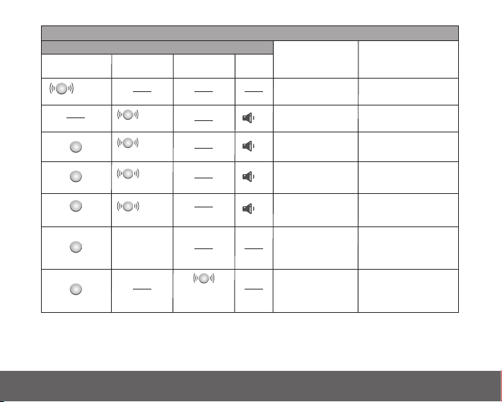
Fault modes and Memory indicator
Replace
Alarm
every
48 sec
Low battery
backup
Replace
Alarm
Sensor
fault
Replace
Alarm
End of Life
when pressing
tes/hush button
1 ON when AC mains power is switched on, flashes every 48s when on backup battery, OFF when both AC mains
and backup battery are off.
2 If you are unsure of the amount of flashes of the Yellow LED you can at any time while a fault condition
exists, press the test/hush button. The relevant number of flashes will then be 8s apart.
Note: Fault chirps can be silenced by pressing the test/hush button.
There has
been an
alarm in
your absence
Check Alarm
memory
section
Flashes as
per fault type
Fault chirps have been
silenced. Rate of the
yellow LED flashing
indicates fault type
If required chirping can be
silenced again by pressing
test/hush button
What you hear / see
x2
x1
x1
x1
x2
x3
every
48 sec
x3
48
Page 49

The Alarm can communicate its status and history through various Led flashes and chirps/beeps.
However, a more comprehensive report of all such events is available through the AudioLINK
download via the smart phone App.
Low Battery Backup Fault
If the battery backup supply is depleted, the sounder will give one short chirp with one yellow LED
fault indicator flash every 48 seconds. In this case check that the green LED power indicator is on
continuously. If it is off, or flashing every 48 seconds, the Alarm is not receiving 230V AC mains power
and is being powered by the battery backup. The chirp every 48 seconds indicates that the battery is
depleted. The battery is not replaceable. Check fuses, circuit breakers and wiring to determine the cause
of the interruption to the mains power. If in doubt, contact a qualified electrician. Once mains power is
reinstated, the chirps should cease within 2 hours as the battery charges up. If the chirping persists for
over 2 hours with the green light on, there may be some other problem with the Alarm. The Alarm must
be returned for repair or replacement - see GETTING YOUR ALARM SERVICED section.
Sensor Fault
The Alarm regularly checks the optical smoke sensor, thermistor heat sensor and CO sensor for correct
operation. If the Alarm has found a fault with the sensor, it will give 2 short chirps with 2 yellow LED
flashes every 48 seconds. In this case, the Alarm must be returned for repair or replacement - see
GETTING YOUR ALARM SERVICED section.
End of Life
Once the Alarm passes its 10th year of installation, it will give 3 short chirps with 3 yellow LED flashes
every 48 seconds to indicate it has reached its end of useful life.
The entire Alarm must be replaced (Also check the replace by date on the label on the side of the
Alarm). Disconnect the mains first and replace the Alarm - see ‚Removing the Alarm‘ section.
49
Page 50

Maximum Dust Compensation
The Alarm monitors the dust contamination build-up in the optical smoke chamber and then
compensates for it, reducing the possibility of false alarms.
If however, the Alarm gives 4 short chirps with 4 yellow LED flashes when the test/hush button is pressed,
it indicates that the Alarm has reached the maximum dust compensation. When this occurs , the Alarm will
continue to operate as normal, but there is an increased risk of false alarms caused by dust contamination.
If contamination has occurred quickly (e.g. due to dust from carpets being replaced) and the Alarms
are sounding, the dust compensation may take some hours to operate. In this situation, remove the
Alarm from the ceiling, leave it disconnected for 5 minutes, then reinstall the unit (the air must be
clean i.e., dust and smoke free). The dust compensation will now operate quickly, within 60 seconds.
Temporarily Silencing the Fault chirps
If the test/hush button is pressed on an Alarm that is giving fault chirps and yellow LED fault indicator
flashes, the Alarm will be silenced (Fault Hush mode) for a period of 12 hours. However, the Alarm
will sound / function as normal within that period should it detect Fire (except if the fault detected
is a sensor fault). The yellow LED fault indicator will continue to flash as before to indicate the fault
is still present. This is a useful feature should the fault occur at night as it keeps the disturbance at
a time when people in the building are trying to sleep to a minimum. The fault chirps would return
12 hours later, which perhaps may be a more suitable time to address the fault issue with the Alarm.
In case of low backup battery voltage and end of life fault chirps, this can be repeated as required.
A sensor fault condition can only be hushed once.
50
Page 51

Your Alarm does not
sound when you press the
test/hush button
Your Alarm sounds for no
apparent reason
• Check the Alarm is secured correctly on the mounting plate.
• Wait 15 seconds after connecting the power before button testing.
• Hold button down firmly for at least 10 seconds.
• If the alarm does not sound, then your Alarm must be returned for repair
or replacement - see “GETTING YOUR ALARM SERVICED” section
• Follow the detailed instructions in section 5 and/or section 6
regarding the alarm condition.
• Locate the Alarm that sounds and has a flashing red LED.
• Identify the alarm type – Fire or CO.
• For Fire:
- If you have thoroughly investigated and are sure that it is just a
nuisance alarm, simply press the test/hush button briefly to silence
the Alarm and any interconnected devices for 10 minutes. When
the Alarm is in ‘Hush’ mode the red LED will continue to flash while
it detects the presence of heat.
The Alarm will reset to normal functionality at the end of the 10
minute. If additional silenced time is required, simply push the test/
hush button again.
- If you experience frequent nuisance/false alarms, it may be
necessary to re-locate the Alarm away from the source of the
fumes or if it continues to sound without smoke or heat being
present and cleaning the Alarm does not solve the problem, it needs
to be replaced.
51
Page 52

• For CO:
- Ensure there are no fuel burning appliances in the vicinity which
could be leaking CO gas (e.g. even from next door).
- Ensure there are no fumes or aerosols in the area (e.g. paint,
thinners, hair spray, chemical cleaners, aerosol sprays, damp
proofing done with and aqueous emulsion such as Aminofunctional
siloxane and Alkylalkoxysilane) which can cause false CO alarms.
- Ensure there is no outdoor source of CO in the vicinity (e.g. a car
with engine running, heavy traffic, heavy air pollution, barbecue
fumes etc).
- Ensure there is no source of hydrogen such as batteries being
charged (e.g. on boats or in Uninterruptable Power Supplies (UPS)),
as this can lead to false CO alarms.
- Ensure there is not excessive smoke or fumes from devices such as
Egyptian shisha, hookah or hubbly bubbly pipes, especially those
that use coal or charcoal to heat the tobacco.
- Press the test/hush button to silence the Alarm for 4 minutes.
- If the CO Alarm continues to sound it is possibly defective and
should be replaced.
52
Page 53

Interconnected Alarms
do not all sound
Pressing the test/hush
button does not silence
the Alarm
Your Alarm chirps/beeps/
flashes
• Hold test/hush button for 10 seconds after the first alarm has sounded
to ensure signal is transmitted to all units.
• If this is not the case and you have a hardwired interconnection, we
recommend you consult a qualified electrician.
• If the Alarm is fitted with an RF module for wireless interconnection,
check that all Alarms in the RadioLINK system are powered and are
house-coded correctly. (see the Ei3000MRF RadioLINK+ module
manual).
Always make sure that you are pressing the test/hush button on the
Alarm that sounds with the red LED flashing.
In standby mode, the Alarm does not sound, beep, chirp or flash. The
only light on is the green power LED.
The Alarm automatically monitors the battery, sensor and electronics
periodically to ensure that all are satisfactory. If a fault has been found,
the alarm alerts the occupier to this via short chirps from its sounder
and yellow LED fault indicator flashes every 48 seconds. The alarm will
also indicate any faults when the test/hush button is pressed.
See fault modes and memory indicator table.
53
Page 54

8
Limitations of Fire
and CO Alarms
54
Page 55

Multi-Sensor Fire and Carbon Monoxide Alarms can significantly help to reduce the risk of fire and
CO fatalities. However independent authorities have stated that these systems may be ineffective in
some situations. There are a number of reasons for this:
• The Alarms will not work if the mains power supply is off or disconnected and the backup battery
is depleted. Test regularly to ensure the power supply is functioning as required.
• The Alarms will not detect the danger if sufficient Smoke/Heat/CO does not reach the Alarms.
Smoke/Heat/CO may be prevented from reaching the Alarm if the fire / burning fuel appliance is
too far away, for example, if it is on another floor, behind a closed door, in a chimney, in a wall
cavity, or if the prevailing air drafts carry the Smoke/Heat/CO away.
• The Alarms may not be heard. The sound output is loud but it may not be heard behind a closed
door or if it is too far away. Interconnecting Alarms greatly improves the probability that they will
be heard. The Alarm may not wake up somebody who has taken alcohol or drugs. The alarm sound
may be masked by other sounds such as T.V., stereo, traffic noise etc. This Alarm is not designed for
people with impaired hearing.
• The Alarms may not detect every type of fire to give sufficient early warning.
• The Alarms don’t last indefinitely. The manufacturer recommends regular testing and replacement
after, at most, 10 years, as a precaution.
• This Alarm is not a substitute for life insurance. House-holders are responsible for their own
insurance. The Alarm warns of increasing CO levels, but we do not guarantee that this will protect
everyone from CO poisoning.
55
Page 56

• This Alarm does not detect the presence of natural gas (methane), bottled gas (propane, butane)
or other combustible gases. Fit combustion gas alarms to detect these.
Not e: This Alarm contains an electrochemical sensor which has a cross sensitivity to hydrogen. This
means that they can alarm due to sensing hydrogen
WARNING: THIS AL ARM IS DESIGNED TO PROTECT INDIVIDUALS FROM THE ACUTE EFFECTS OF
CARBON MONOXIDE EXPOSURE. IT WILL NOT FULLY SAFEGUARD INDIVIDUAL S WITH SPECIFIC
MEDICAL CONDITIONS. IF IN DOUBT CONSULT A MEDICAL PRACTITIONER.
56
Page 57

9
Important
Safeguards
57
Page 58

When an Alarm system is installed, basic safety precautions should always be followed, including
those listed below:
• Please read all instructions.
• Use the testing of the Alarm as a means to familiarise your family with the alarm sound. Rehearse
emergency escape plans so everyone at home knows what to do in case the Alarm sounds. Further
information can be obtained from your local fire prevention officer.
• To maintain sensitivity to Fire/CO, do not paint or cover the Alarm in any manner and; do not allow
cobwebs, dust or grease to accumulate.
• If the Alarm has been damaged in any way or does not function properly, do not attempt a repair.
Return the Alarm - see Section 10 ‘SERVICE AND GUARANTEE‘ section.
• This appliance is only intended for premises having a residential type environment.
• Alarms are not a substitute for insurance. The supplier or manufacturer is not your insurer.
• Do not dispose of your Alarm in a fire.
58
Page 59

10
Service and
Guarantee
59
Page 60

10.1 Getting your Alarm serviced
If, within the guarantee period, your Alarm fails to work after you have carefully read all the
instructions, checked the unit has been installed correctly, and is receiving AC power, then contact us.
If you are advised to return your Alarm, please ensure that the Alarm is placed in a padded box,
not attached to the mounting plate (as the Alarm can give beeps or alarm if the test/hush button
is pressed during shipping), with the proof of purchase and a note stating the nature of the fault.
10.2 Guarantee
Aico guarantees this Alarm for five years from the date of purchase against any defects that are
due to faulty materials or workmanship. If this Alarm should become defective within the guarantee
period, we shall at our discretion repair or replace the faulty unit.
This guarantee only applies to normal conditions of use and service, and does not include damage
resulting from accident, neglect, misuse, unauthorised dismantling, or contamination howsoever
caused. This guarantee excludes incidental and consequential damage.
This guarantee does not apply to any product that has been modified in any way by a third party or
has been fitted with a third party element.
Do not interfere with the Alarm or attempt to tamper with it. This will invalidate the guarantee but
more importantly may expose the user to shock or fire hazards.
This guarantee is in addition to your statutory rights as a consumer.
60
Page 61
The crossed out wheelie bin symbol that is on your
Block E1
product indicates that this product should not be disposed
of via the normal household waste stream. Proper
disposal will prevent possible harm to the environment or
to human health. When disposing of this product please
separate it from other waste streams to ensure that it can
be recycled in an environmentally sound manner. For
more details on collection and proper disposal, please
contact your local government office or the retailer where
you purchased this product.
61
Page 62
KM522831
KM83678
KM86596
EN14604: 2005 + AC 2008
BS 5446-2: 2003
EN 50291-1: 2 018
62
Page 63
2797
0086
Ei Electronics, Shannon, Co. Clare, Ireland Ei Electronics, Shannon, Co. Clare, Ireland
23
DoP No. 23-0001
23
DoP No. 23-0001
EN14604:2005 + AC:2008
Smoke Alarm Devices:
Ei3030
Fire Safety
Nominal activation conditions/ sensitivity,
response delay (response time) and
performance under fire condition
Operational reliability Pass
Tolerance to voltage supply Pass
Response delay and temperature resistance Pass
The Declaration of Performance may be consulted at www.eielectronics.com/compliance
Pass
Vibration resistance Pass
Humidity resistance Pass
Corrosion resistance Pass
Electrical stability Pass
63
Page 64

An Ei Company
P/N B20665 Rev1
© Ei Electronics 2023
64
Aico
Oswestry, Shropshire SY10 8NR, U.K.
Tel: 01691 664100
www.aico.co.uk
 Loading...