

Page 1
CHECK OPERATION OF ALARM
GREEN MAINS LIGHT IS ON.
TEST BUTTON OPERATES ON ALL ALARMS.
ALL INTERCONNECTED ALARMS OPERATE WHEN
EACH TEST BUTTON IS PRESSED FOR 10 SECONDS.
(Ei144/146 ONLY) IF THE UNIT BEEPS EVERY 40 SEC
-
ONDS FOR OVER20 MINUTES THE BATTERY IS PROB
ABLY DEPLETED. REMOVE UNIT FROM CEILING (SEE
FIG 1) AND REPLACE BATTERY. ON THE Ei164/166
UNITS ALLOW CELLS TO CHARGE FOR 2 HOURS
(MAINS ON).
DO NOT ATTEMPT TO OPENTHE ALARM AS IT IS PER
MANENTLY SEALED FOR SAFETY.
IF A NUISANCE ALARM OCCURS PRESS THE
TEST/HUSH BUTTON TO SILENCE THE ALARM FOR 10
MINUTES.
SMOKE ALARMS
Sufficient smoke must enter the Smoke Alarm before it will re
spond. The Smoke Alarm needs to be within 7.5 metres of the
fire torespond quickly. It also needsto be in aposition where its
alarm can be heard throughout your home, so it can wake the
occupants in time for all to escape. A single
Smoke Alarm will
give some protection if it is properly installed, but most homes
will requiretwo
or moreto ensure thata reliable early warningis
given. Formaximum protectionyou should putindividual Smoke
Alarms in all the rooms where fire is most likely to break out,
(apart from kitchens etc. see Locations to Avoid).
A Smoke Alarm should be located between the sleeping area
and the mostlikely sources of fire (living room orkitchen for ex
ample), but itshould not be more than 7.5metres from the door
to anyroom wherea fire mightstart on theescape route fromthe
house.
Important: These Smoke/Heat Alarms are designed for a sin
gle occupancy in a residential type environment.
A Smoke Alarmshould be sited within 3m ofbedroom doors for
improved audibility.
HEAT ALARMS
The HeatAlarm givesa fire warningwhen thetemperature at the
unit reaches58°C. Itis ideal forkitchens, garages, boilerhouses
and other areas where thereare normally high levels of fumes,
smoke or dust i.e. places where Smoke Alarms cannot be in-
stalled without the risk of excessive nuisance alarms.
A HeatAlarm shouldonly be usedin a roomadjoining anescape
route, inconjunction withSmoke Alarms onthe escaperoutes.
All the Heat Alarms and Smoke Alarms should be intercon
nected to ensurethe early warning will be heard,particularly by
somebody sleeping.A properly designed earlywarning fire sys
tem ensures the alarm is given before the escape routes be
come blocked with smoke. Therefore, there must be Smoke
Alarms along the escaperoutes as Heat Alarms would not give
sufficient warning. However, a fire in a closed room (e.g.
kitchen) adjoining the escape route, can eventually cause the
corridor to become smoke-logged due to smoke leaking out
from around thedoor before adequate warning can begiven by
detectors in the corridor. (Smoke leakingout from a room is of
ten cool andslow moving so itcan take a long timeto rise to the
ceiling, and travel to a detector which could be some distance
away). AHeat Alarmin the closedroom will giveearly warningof
fire in that room and help overcome this problem.
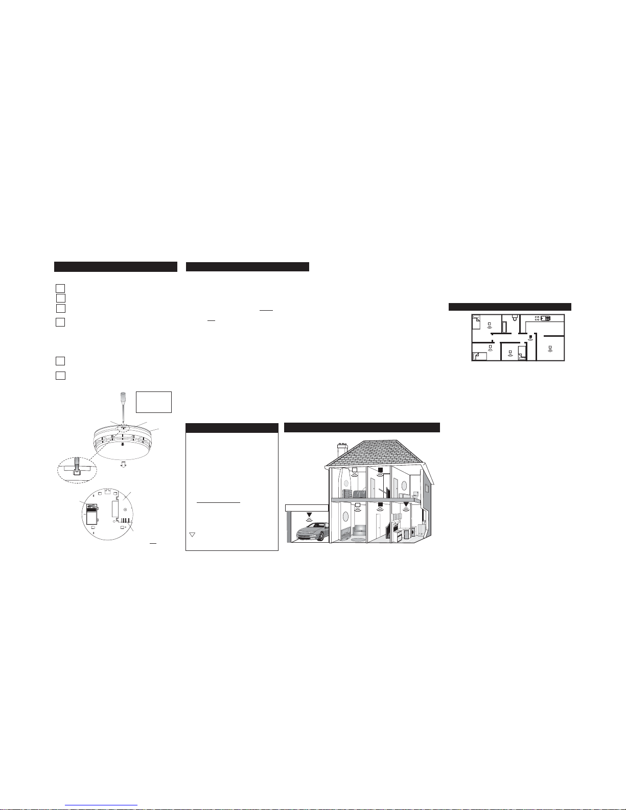
RECOMMENDED LOCATIONS
Figure 2 illustrates where Smoke Alarms and Heat Alarms
should be located in a typicaltwo storey house. Note the spacings in “Recommended Protection” which ensure the early detection of fire and that warning will be heard.
Locate Heat Alarms in rooms adjoining or on escape routes kitchens, garages, boiler housesetc. where Smoke Alarms are
unsuitable. Install within 5.3m of potential sources of fire.
Single Storey Dwelling.
If the Home is onone level (a bungalow or mobile home for ex
-
ample) youshould put thefirst Smoke Alarmin a corridoror hall
way between the sleeping and living areas. Place it as near to
the living areaas possible, but make sureyou can hear it loudly
enough towake aperson in thebedrooms. (for example,see fig
ure 3)
If the bungalowis very large and the corridoror hallway is more
than say15 metres long,one Smoke Alarm willnot be sufficient.
This isbecause no matter where itis located it willbe more than
7.5 metres from potential fires.
In houses with more than one sleeping area, Smoke Alarms
should be placed between each sleeping area and the living
area.
Multi Storey Dwellings
If the dwelling has more than one storey it must have an interconnected alarm on each level for minimum protection.
Maximum Protection
For maximum protection you should put individual Smoke
Alarms in all the rooms where fire is most likely to break out
(apart from the locations to avoid, mentioned below). Ensure
that theyare allinterconnected. The livingroom isthe most likely
place for afire to start at night, followed bythe kitchen and then
the dining room. You should also consider putting Smoke
Alarms in any bedrooms where fires might occur, for instance,
where thereis anelectrical appliance suchas an electricblanket
or heater, or where the occupant is a smoker. You could also
consider putting Smoke Alarms in any rooms where the occu
pant is unableto respond very well to afire starting in the room,
such as an elderly or sick person or a very young child.
BEDROOM
BEDROOM BEDROOM
KITCHEN
DINING
Figure 3
5
PAGE 2,3,4&5
B13729
REV-1
READ THIS FIRST
CONT.
Single Storey Dwelling with Recommended Protection
8
?
4
4
MOUNTING PLATE
SEALING
GASKET
TAMPERPROOF
CATCH
PUSH SCREWDRIVER
STRAIGHT IN
TO RELEASE CATCH
SLIDE
OFF
WARNING:DISCONNECT MAINS
BEFORE REMOVING ALARM
(PUSH COVER BACK)
UNIT WILLNOT FIT
ON THE MOUNTING
PLATEWITHOUT A
BATTERYINSTALLED
(EI141/144/146 ONLY)
Figure 1a
LOCATING ALARMS
4
4
Multi Storey Dwelling with Recommended Protection
Recommended Protection
See Figures2&3
Minimum protection
+
Smoke Alarms located on:-
·
each storey
·
every 7.5 metres of hallways and
escape routes
·
within 3m of all bedroom doors.
- Interconnect all Alarms -
Maximum protection
1
Smoke Alarms located as above plus:
·
All rooms (except bathroom, shower
rooms & kitchens)
Heat Alarms located in Kitchens,
garages, boiler rooms etc. within 5.3m
of potential fire sources.
BASE
4WAYPLUG
ENGAGES SOCKET
ON MOUNTING PLATE
TO CONNECT MAINS BATTERYAND
9
V
olt
Battery
BATTERY
SNAPS
(EI141/144/146
ONLY)
Figure 1b
Figure 2
2
4
Page 2
Checking you can hear the Smoke & Heat Alarms
With the Alarm soundingin its intended location, check you are
able to hear itin each bedroom with the door closed,above the
sound ofthe radio. The radioshould be set toa reasonably loud
conversation level. If you can’t hear it over your radio the
chances are that it wouldn’t wake a person.
If aSmoke Alarm is toofar away forit to wakea person, it isbest
to lnterconnect to another SmokeAlarm or HeatAlarm near the
bedroom. The alarms can be interconnected -when one alarm
senses smoke, all interconnected alarms respond (see below
for further details).
LOCATIONS TO AVOID
Don’t place Smoke Alarms in any of the following areas:
·
Bathrooms, kitchens, shower rooms, garages or other
rooms where the smoke alarm may be triggered by steam,
condensation, normal smoke or fumes. Keep at least 6
metres (20 feet) away from sources of smoke.
Don’t place Heat Alarms in any of the following areas:
·
Bathrooms, shower rooms or other room where the unit
may be triggered by steam or condensation.
Don’t place Smoke or Heat Alarms in any of the following areas:
· Places where the normal temperature can exceed 40°C or
be below 4°C e.g. attics, furnace rooms etc. directly above
ovens or kettles, as the heat/steam couldcause nuisance
alarms.
·
Near adecorative object, door, light fitting,window moulding etc., that may prevent smoke or heat from entering the
Alarm.
· Surfaces that are normally warmer or colder than the rest
of the room (forexample attic hatches, uninsulated exterior
walls etc). Temperature differences might stop smoke or
heat from reaching the unit.
·
Next to or directly above heaters or air conditioning
vents, windows,wall vents etc. thatcan change thedirec
-
tion of airflow.
·
In veryhigh or awkward areas(eg. over stairwells) whereit
may be difficult to reach the alarm (for testing, hushing or
battery replacement).
·
Locate awayfrom verydusty or dirtyareas asdust build-up
in thechamber canimpair performance. Itcan also blockthe
insect screen mesh and prevent smoke from entering the
smoke detector chamber.
·
Locate theunit at least 1 metrefrom dimmer controlled lights
and wiring - some dimmers can cause interference.
·
Locate unitat least1.5m androute wiringat least 1m awayfrom
fluorescent light fittings aselectrical “noise” and/or flickering
may affect theunit. Do not wire into thesame circuit as fluores
-
cent lights or dimmers.
·
Do not locate in insect infested areas. Small insects get
ting intothe smoke detectorchamber can causeintermittent
alarms. Insects and contamination onthe Heat Alarm sen
sor can increase its response time.
·
The locationsmust complywith applicable buildingregulations.
Hot smokerises and spreads out, soa central ceiling positionis
the preferred location. The air is “dead” and does not move in
corners, therefore Smoke & Heat Alarms must be mounted
away from corners. Place the unitat least 0.5m ) from any light
fitting ordecorative objectwhich might obstructsmoke / heaten
-
tering the Alarm. Keep at least 0.5m away from walls. See fig
ure 4.(Smoke Alarms shouldbe locateddirectly on theceiling or
up to 0.57mbelow it. Heat Alarms should be locateddirectly on
the ceiling or up to 90mm below it).
Wall mounting is not recommended for these Alarms.
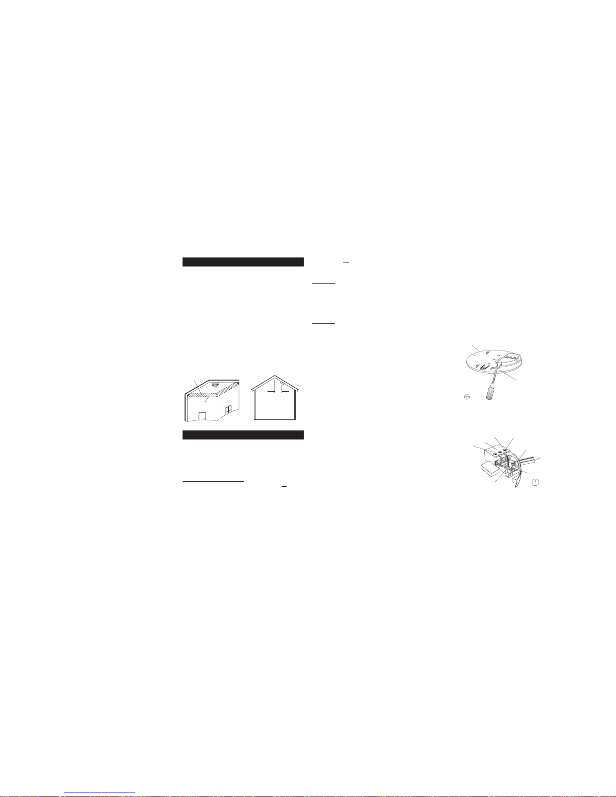
Sloping Ceiling
In areaswith sloping orpeaked ceilings installyour Smoke/Heat
Alarm 0.9m from the highest point measured horizontally (see
figure 5), because “dead air” at the apex may prevent smoke
from reaching the unit.
The Alarm is designed to be permanently mounted , using it’s
own built-interminal block toconnect itto the mains.The mount
ing plate can be screwed directly to the ceiling. Alternatively it
can bescrewed to a standard junctionbox. It requires acurrent
of 40mA. TheAlarm must not be exposedto dripping or splash
ing. Thereare importantmarkings on theunderside ofthe alarm.
IMPORTANT PRECAUTION: Do not install the actual
alarm itself in new or renovated buildings until all
work is
completed (including floorcoverings) and the buildinghas
been fullycleaned. The wiringcan be installed whenappro
priate. (Excessive dust and debris from building work can
contaminate the smokechamber or heat sensor andcause
problems, it willalso invalidate the guarantee).If it must be
installed, cover it completely, particularly around the
edges, witha dustcover (eg. withthe elasticated coversup
plied or a plastic bag), until all cleaning is finished.
The Alarmmust not
be connectedwhen the housewiring insula
-
tion is being checked with high voltages.
WARNING:
Mains operated Alarms should beinstalled and in
terconnected by a qualified electrician in accordancewith local
institutions. Failureto installthis Alarm correctlymay expose the
user to shock or fire hazards.
An ALL-POLE MAINS SWITCH witha contact separation of at
least 3mmin each poleshall be incorporated inthe electricial in
stallation of the building.
WARNING:
The Alarmmust be continuously powered24 hours
a dayso it isimportant that itis not on acircuit that canbe turned
off by a switch.
INSTALLATION
1. Select a location complying with the above advice.
2. Disconnect theAC mains supply from the circuitthat is going
to be used.
3. Remove the mounting plate from the Smoke/Heat Alarm by re
leasing thetamper-proof catch with asmall screwdriver asshown in
figure 1 and sliding the Alarm from the plate.
4. The housewiring must be connected tothe terminal block on
the mounting plate as follows:
L: Live - connect to the house wires coloured brown, red or
marked L.
N: Neutral - connect to the house wires coloured blue, black or
marked N.
IC: Interconnect - connectto the third core. (If you arenot inter
connecting units, do not connect anything to the IC terminal).
(See below for information on interconnecting).
Warning: Mixing Live & Neutral wires will damage intercon
nected alarms.
We recommend the use of 6243Y mains cable when intercon
necting units. Use the third core for interconnection.
Do not use an earth wire for the interconnect line.
Lift off the wiring cover as shown in Fig 6.
N.B. Thealarm does notneed to beearthed. However theterminal marked is providedfor the convenienceof theinstaller so
that any copper earth wire or cable coloured green or green &
yellow, can be safely terminated.
To interconnectthe Alarms connect allthe IC terminalstogether
as shown in Figure 8.
5. If the mains wires are recessed, bring the wires through the
rear hole in the mounting plate as shown in figure 7.
If the mains wires are being brought along the surface:
(a) positionthe mounting plateso the cabletrunking is as shown
in figure 7.
PAGE 6,7,8&9
B13729
REV-1
7
6
8
9
POSITIONING SMOKE & HEAT ALARMS
INSERT SCREWDRIVER
TO LIFT AND REMOVE
WIRE COVER
N
IC
L
CEILING GASKET
(MUST BE IN PLACE)
Figure 6
TERMINAL
SCREWS
EARTH
(IF PRESENT)
(TRUNKING)
RECESSED WIRING
KNOCKOUT FOR
SURFACE CABLE ENTRY
(LEAVETOP INTACT)
N - NEUTRAL
L -LIVE
IC - INTERCONNECT
Figure 7
Figure 5
Figure 4
IDEAL IN CENTRE
OF CEILING
NEVER WITHIN
300mm OF ANY
WALL / CORNER
DEAD AIR
SPACES
INSTALLING SMOKE & HEAT ALARMS
90cm
900mm
(3 ft)
Page 3

(b) carefully cut around the knockouts on the two alarm side
walls so it blends with the contours of the alarm sidewall.
Important: only cut the thinned down knockout section and
leave thetop intactas shown. Thereis only oneposition suitable
for the surface wiring to enter the alarm.
6. Carefully alignthe mounting plate andscrew into place. Con
-
nect the wires to the terminal block. With recessed wiring, en
sure the rear gasket seals around the edge of the hole in the
ceiling or wall. This is to prevent air draughts affecting the
smoke / heat entering the alarm. If the orifice is too large it
should be sealed with silicone rubber or equivalent.
Replace the wiring cover. Check the battery is connected (140
series only).
Carefully line up the unit on the base and slide on.
Press thetest/hush buttonfor 10 seconds.The hornwill sound.
CAUTION: Do not attemptto remove the Alarm without first re
leasing the tamper clip as shown in Figure 1.
7. Connect the mains power to the alarm circuit. Check the
green light is on. Attach the label provided to the distribution
board to identify the alarm circuit.
Attach the‘Mains Smoke/ Heat Alarm’label onor near thedistribution board and write in date installed and the number of
alarms on the circuit.
Check the operation of the Alarm as outlined below.
INTERCONNECTING
EI ELECTRONICS SMOKE / HEAT
ALARMS
Note: Amaximum oftwelve Ei143/144/145/146/ 164/166Smoke or
Heat Alarms maybe interconnected along with an Ei
128 pattress
with relay (see Accessories below).
(If youwish to connectmore than twelvealarms contact yourdistrib
utor). Systemsusing more than 3or 4 alarms mustbe very carefully
planned to ensure nuisance alarms are not excessive. e.g. from
cooking or weekly testing.
·
Smoke Alarm Locator Switch (EI 159) should be incorpo
-
rated into the system and be readily accessible to all occu
-
pants sothat thesource of analarm canbe quickly identified.
·
All alarms must be cleaned and maintained regularly.
·
A qualified person must be on call to quickly remove any
faulty alarms (i.e. units with red light flashing), which are
causing all the alarms to sound.
WARNING: Donot connectthese Alarms toany other typeof Ei
Alarm, or to any other model produced by another manufac
-
turer, apart from thoselisted above. Doing this may damage the
Alarms and could result in a shock or fire hazard.
The interconnectwire (minimum0.75mm
2
cable) mustbe treated as
if it was live. It should be insulated and sheathed.
A maximumof 250metres of wirecan beused (maximum resistance
between detectors 50 ohms).
These Smoke/HeatAlarms shouldbe interconnected onlywithin the
confines ofa single family livingunit. If theyare connected between
different units theremay be excessive nuisance alarms.Everybody
may not be aware thatthey are being tested or that it is a nuisance
alarm caused by cooking etc.
INSPECTION & TESTING PROCEDURE
After installation check all the Alarms
We recommend thatthe functioning of the mains batteryback-up is
checked directly after installation as follows:
(i) Turn offthe mains power at the distributionboard and check that
the green mains indicator on the alarm is extinguished.
(ii) Press the testbutton and ensure that the horn sounds loudly for
10 seconds. Ensure that any interconnected alarms also sound.
(iii) Repeatthe process on all interconnectedalarms on the system.
Turn the mains power on only if the units pass the above test.
(iv) Check thatthe green mains indicator lightis on. (If it isoff check
circuit breakers, fuses and wiring etc.) Check the red light on the
cover flashes every 40 seconds.
(v) Press the test button for up to 10 secondsto ensure the sensor
chamber, electronics andsounder are working. The red lighton the
cover willflash while horn is sounding.The alarm will stop whenthe
button is released. Pressing the test button simulates the effect of
smoke or heat during a real fire and is the best way to ensure the
Alarm is operating correctly.
WARNING: DO NOT TEST WITH FLAME.
This can set fire to the Alarm and damage the house.
We do not recommendtesting with smoke or heat as theresults
can be misleading unless special apparatus is used.
Interconnected alarms
Test the firstunit by pressing thebutton. All the detectors should
alarm within about 5 seconds of the first horn sounding and the
red light on thefirst unit only will flash once a second. Checkall
the otherunits similarly. (Note:Heat alarms signal toother inter
connected alarms about4 seconds after their own horn sounds.
Optical alarms signal within about a second.
Checking Battery Back-up
When the unit is beeping:
The Alarm automatically monitors the battery every 40 seconds to
ensure that it is satisfactory. Ifit is depleted it will give a short beep
every 40 seconds.
Models Ei144 & Ei 146 only
Before replacingthe battery,check that thebeeps arenot due toone
of the following:
(i) battery snaps not connected properly.
(ii) Onthe Optical SmokeAlarm only (
EI 146/145)if the unitbeeps
and the redlight does not flash atthe same time it indicatesa prob
lem with the smokechamber - see Cleaning the Smoke Alarm section below.
If the beeps have continued for over 20 minutes (and the other
causes of beepshave been ruled out -see below) the battery must
be replaced.
(iii) Switch off themains and remove the unit as shownin figure 1a.
Remove depleted battery and replace with one of the specified 9V
alkaline batteries. The alarm cannot be replaced on the mounting
plate unless a battery is installed. After replacing the battery, slide
on the mounting plate then press the test button and ensure horn
sounds loudly before you turn on the mains. Ifit is satisfactory turn
on the mains and check that the green light comes on. Note: Only
use the specified Alkaline batteries shown on the base label
(Duracell MN1604 or Eveready522). We recommend that the “use
by date” onthe battery should still haveat least 2 years togo. Older
batteries will give beeps prematurely.We recommend that the bat
tery is replaced each year for optimum performance.
Models Ei161, Ei164 & Ei 166 only
(i) Check that thegreen mains power light is on. Ifit is off the Alarm
has beenpowered fromthe cells andthe beeps indicatethey are de
pleted. Re-connect the mains,check fuse, circuit breakers and wir
ing. If in doubt contact a qualified electrician. The beeps should
cease within 2 hours as the cells charge up.
(ii) The cells may be depleted. The beeps should cease within 2
hours asthey charge up. Fullycharged, the cells willprovide up to 6
months back-up without mains power.
(iii) On the Optical Smoke Alarms only (
EI 166) if the unit beeps
and the redlight does not flash atthe same time it indicatesa prob
lem with the smoke chamber - see Cleaning the Smoke Alarm.
If all ofthe above possible causes ofbeeps have been ruled outbut
the beepinghas stillpersisted for over2 hours withthe green lighton
- the rechargeable cells are probably defective. The Smoke / Heat
Alarm must be returned to the manufacturer for repair or replace
-
ment (see section Getting Your Alarm Serviced).
(Please note:The ionisation alarms(EI140/141/161) give twoshort
beeps abouta second apart atthe end of thehush period (i.e. about
10 minutes after test/hush button has been pressed. These two
beeps should not be confused with low battery beeps.
(a) Relay Module
EI 128:
The Ei128 module has a relayrated 250V AC /5 amps. This isuse
-
ful for remote signalling and turning on lights.
(b) Smoke Alarm Locator Ei 159:
The SmokeAlarm locator isrecommended for systemswith three or
more Smoke / Heat Alarms as it helps quickly identify the unit in
alarm and reduces the impact of nuisance alarms.
Pressing the Smoke Alarm Locator button will silence all interconnected alarms for 10 minutes, exceptthose sensing fire. It is easily
installed between the interconnect and neutral terminals.
(2) The Heatalarms (Ei 143/144/164) give twobeeps 10 minutes
after the test/hush button is pressed.
(3) Ifthe Optical units(EI 146/145/166) beepswithout the redlight
flashing atthe same time, thechamber is defective.Clean the
chamber.
4. INTERCONNECTED ALARMS DO NOT ALL SOUND:
(1) Holdtest button for10 seconds afterfirst alarm has sounded
to ensure signal is transmitted to all units.
(2) Switch off mains and check that live, neutral and intercon
-
nect cableshave beencorrectly connected andthat the con
-
nections are tight.
10
11
12
13
CHECKING THE OPERATION OF THE
ALARMS
PAGE 10,11,12&13
B13729
REV-1
ACCESSORIES
Figure 8
L - LIVE
N - NEUTRAL
IC -I
NTERCONNECT
TROUBLESHOOTING
CONT.
Page 4

1. FREQUENT NUISANCE ALARMS OCCUR:
(1) Close kitchen / bathroom door when in use.
(2) Ensurethat the alarmis sited at least6m away fromsources
of fumes.
(3) Contamination from insects,paint or paint fumes may have
occurred. Clean the alarm - see “User Instructions” leaflet.
(4) If theproblem persists, resiting of theunit should be consid
-
ered.
2. ALARM SOUNDS FOR NO APPARENT REASON:
(1) Identify the alarm source. On interconnected units, the red
light on the cover will flashrapidly only on the unit which is
the source of the alarm.
(2) Check for fumes, steam etc. from the kitchen or bathroom.
Paint and other fumes can cause nuisance alarms.
(3) Pressthe test/hush button tosilence the Smoke/HeatAlarm
for 10 minutes.
(4) Ifalarm does notstop, switchoff mains andremove unit (see
figure 1).
(Only remove alarm with red light flashing, the others are
probably satisfactory).
3. LOW BATTERY & OTHER BEEPS:
(On Ei144/146 only)
If the batteryis correctly connected and the unithas beeped for
over 20 minutes thebattery is probably depleted. Obtain a new
battery, disconnect the mains, then remove the alarm and re
-
place the depleted battery.
(On Ei164/166 only)
Check the green mainspower light is on. If not, check fuse, cir
cuit breakersand wiring connections. Ifthe green light isoff, the
lithium cells will deplete after some months without mains and
will need tobe recharged. If the above fails toturn on the green
light, a fault may exist. Switch off mains and remove the unit
(see figure 1).
(All Alarms)
(1) If thegreen mains light is onand replacing battery, recharg
-
ing lithium cells or cleaning unit has not stopped beeps, a
fault may exist. Disconnect the mains first and replace the
unit (see figure 1).
PAGE 14 & 1
B13729
REV-1
TROUBLESHOOTING
IDEALLY INSTALL IN THE CENTRE OF CEILING AT
LEAST 0.5m FROM LIGHT FITTINGS.
REMOVE UNITFROM MOUNTINGPLATE BY RELEASING
CATCH AS SHOWN IN FIG 1a.
Ei144/146 ONLY: CHECK BATTERY IS CONNECTED TO
SNAP (SEE FIG 1b). BATTERY WILL NOT POWER THE
UNIT UNTIL IT IS SNAPPED ON TO THE MOUNTING
PLATE.
ENSURE HOUSE LIVE MAINS IS CORRECTLY CON
NECTED TO L TERMINALS ON ALL INTERCONNECTED
ALARMS - OTHERWISE UNITS WILL BE DAMAGED.
DO NOTFIT ACTUALALARM UNTIL ALLBUILDING WORK
IS COMPLETED TO AVOID CONTAMINATION. AFTER
CHECKING OPERATION, COVER SMOKE ALARM WITH
DUST COVER UNTIL REQUIRED FOR USE.
DISCONNECT THE ALARM BEFORE APPLYING HIGH
VOLTAGE TO HOUSE WIRING.
CONT.
-230V AC SMOKE & HEAT ALARMS
SITING & INSTALLATION
INSTRUCTIONS
READ THIS FIRST
4
8
4
8
4
4
LEAVE WITH USER
14
P/N B13729 Rev 1
©
EI Electronics 2001
RECHARGEABLE LITHIUM CELL BACK-UP
ALKALINE 9 VOLT BATTERY BACK-UP
IONISATION
OPTICAL
HEAT
NO BATTERY BACK-UP
EI161 EI164 EI166
EI141 EI144 EI146
EI140 EI145EI143
 Loading...