

eidetic EI-6320-NIR3, EI-6120 NIP-16, EI-6320-NI2 User Manual

Network Video Recorder
User Manual

User Manual of Network Video Recorder
1
Regulatory information
FCC information
FCC compliance: This equipment has been tested and found to comply with the limits for a digital device, pursuant
to part 15 of the FCC Rules. These limits are designed to provide reasonable protection against harmful
interference when the equipment is operated in a commercial environment. This equipment generates, uses, and
can radiate radio frequency energy and, if not installed and used in accordance with the instruction manual, may
cause harmful interference to radio communications. Operation of this equipment in a residential area is likely to
cause harmful interference in which case the user will be required to correct the interference at his own expense.
FCC conditions
This device complies with part 15 of the FCC Rules. Operation is subject to the following two conditions:
1. This device may not cause harmful interference.
2. This device must accept any interference received, including interference that may cause undesired operation.
EU Conformity Statement
This product and - if applicable - the supplied accessories too are marked with "CE" and comply therefore with the
applicable harmonized European standards listed under the Low Voltage Directive 2006/95/EC, the EMC
Directive 2004/108/EC, the RoHS Directive 2011/65/EU.
2012/19/EU (WEEE directive): Products marked with this symbol cannot be disposed of as unsorted municipal
waste in the European Union. For proper recycling, return this product to your local supplier upon the purchase of
equivalent new equipment, or dispose of it at designated collection points. For more information see:
www.recyclethis.info.
2006/66/EC (battery directive): This product contains a battery that cannot be disposed of as unsorted municipal
waste in the European Union. See the product documentation for specific battery information. The battery is
marked with this symbol, which may include lettering to indicate cadmium (Cd), lead (Pb), or mercury (Hg). For
proper recycling, return the battery to your supplier or to a designated collection point. For more information see:
www.recyclethis.info.

User Manual of Network Video Recorder
2
Preventive and Cautionary Tips
Before connecting and operating your device, please be advised of the following tips:
• Ensure unit is installed in a well-ventilated, dust-free environment.
• Unit is designed for indoor use only.
• Keep all liquids away from the device.
• Ensure environmental conditions meet factory specifications.
• Ensure unit is properly secured to a rack or shelf. Major shocks or jolts to the unit as a result of dropping it
may cause damage to the sensitive electronics within the unit.
• Use the device in conjunction with an UPS if possible.
• Power down the unit before connecting and disconnecting accessories and peripherals.
• A factory recommended HDD should be used for this device.
• Improper use or replacement of the battery may result in hazard of explosion. Replace with the same or
equivalent type only. Dispose of used batteries according to the instructions provided by the battery
manufacturer.

User Manual of Network Video Recorder
3
Thank you for purchasing our product. If there is any question or request, please do not hesitate to contact dealer.
The figures in the manual are for reference only.
This manual is applicable to the models listed in the following table.
Model
Type
EI-6320-NIR3
Network Video Recorder
EI-6120 NIP-16
Network Video Recorder
EI-6320-NI2
Network Video Recorder

User Manual of Network Video Recorder
4
Product Key Features
General
Connectable to network cameras, network dome and encoders.
Connectable to the third-party network cameras like ACTI, Arecont, AXIS, Bosch, Brickcom, Canon,
PANASONIC, Pelco, SAMSUNG, SANYO, SONY, Vivotek and ZAVIO, and cameras that adopt
ONVIF or PSIA protocol.
Connectable to the smart IP cameras.
PAL/NTSC adaptive video inputs.
Each channel supports dual-stream.
Independent configuration for each channel, including resolution, frame rate, bit rate, image quality, etc.
The quality of the input and output record is configurable.
Local Monitoring
Simultaneous HDMI, VGA and CVBS outputs.
HDMI output and VGA output at up to 1920×1080 resolution.
Multiple screen display in live view is supported, and the display sequence of channels is adjustable.
Live view screen can be switched in group, and manual switch and automatic cycle live view are also
provided, and the interval of automatic cycle can be adjusted.
Quick setting menu is provided for live view.
Motion detection, video tampering, video exception alert and video loss alert functions.
Privacy mask.
Multiple PTZ protocols supported; PTZ preset, patrol and pattern.
Zooming in by clicking the mouse and PTZ tracing by dragging mouse.
HDD Management
8 network disks (8 NAS disks, or 7 NAS disks+1 IP SAN disk) can be connected.
8 SATA interfaces available
Support eSATA disks for recording or backup.
Support S.M.A.R.T. and bad sector detection.
HDD group management.
Support HDD standby function.
HDD property: redundancy, read-only, read/write (R/W).
HDD quota management; different capacity can be assigned to different channel.
Support disk clone to the eSATA disk.
Recording, Capture and Playback
Holiday recording schedule configuration.
Continuous and event video recording parameters.
Multiple recording types: manual, continuous, alarm, motion, motion | alarm, motion & alarm.
8 recording time periods with separated recording types.
Pre-record and post-record for alarm, motion detection for recording, and pre-record time for schedule
and manual recording.
Searching record files and captured pictures by events (alarm input/motion detection).
Tag adding for record files, searching and playing back by tags.
Locking and unlocking record files.
Local redundant recording and capture.

User Manual of Network Video Recorder
5
Provide new playback interface with easy and flexible operation.
Searching and playing back record files by channel number, recording type, start time, end time, etc.
Smart search for the selected area in the video.
Zooming in when playback.
Reverse playback of multi-channel.
Supports pause, play reverse, speed up, speed down, skip forward, and skip backward when playback,
and locating by dragging the mouse.
Up to 16-ch synchronous playback at 720P real time.
Manual capture, continuous capture of video images and playback of captured pictures.
Backup
Export video data by USB, SATA or eSATA device.
Export video clips when playback.
Management and maintenance of backup devices.
Either Normal or Hot Spare working mode is configurable to constitute an N+1 hot spare system.
Alarm and Exception
Configurable arming time of alarm input/output.
Alarm for video loss, motion detection, tampering, abnormal signal, video input/output standard
mismatch, illegal login, network disconnected, IP confliction, abnormal record/capture, HDD error, and
HDD full, etc.
Alarm triggers full screen monitoring, audio alarm, notifying surveillance center, sending email and
alarm output.
Automatic restore when system is abnormal.
Other Local Functions
Operable by front panel, mouse, remote control, and control keyboard.
Three-level user management; admin user is allowed to create many operating accounts and define their
operating permission, which includes the limit to access any channel.
Operation, alarm, exceptions and log recording and searching.
Manually triggering and clearing alarms.
Import and export of device configuration information.
Network Functions
2 self-adaptive 10M/100M/1000M network interfaces, and various working modes are configurable:
multi-address, load balance, network fault tolerance, etc.
IPv6 is supported.
TCP/IP protocol, PPPoE, DHCP, DNS, DDNS, NTP, SADP, SMTP, SNMP, NFS, and iSCSI are
supported.
TCP, UDP and RTP for unicast.
Auto/Manual port mapping by UPnPTM.
Remote web browser access by HTTPS ensures high security.
Remote reverse playback via RTSP.
Support accessing by the platform via ONVIF.
Remote search, playback, download, locking and unlocking of the record files, and support downloading
files broken transfer resume.
Remote parameters setup; remote import/export of device parameters.
Remote viewing of the device status, system logs and alarm status.
Remote keyboard operation.

User Manual of Network Video Recorder
6
Remote locking and unlocking of control panel and mouse.
Remote HDD formatting and program upgrading.
Remote system restart and shutdown.
RS-232, RS-485 transparent channel transmission.
Alarm and exception information can be sent to the remote host
Remotely start/stop recording.
Remotely start/stop alarm output.
Remote PTZ control.
Remote JPEG capture.
Virtual host function is provided to get access and manage the IP camera directly.
Two-way audio and voice broadcasting.
Embedded WEB server.
Development Scalability:
SDK for Windows and Linux system.
Source code of application software for demo.
Development support and training for application system.

User Manual of Network Video Recorder
7
TABLE OF CONTENTS
Product Key Features .............................................................................................................................. 4
Chapter 1 Introduction .............................................................................................................................. 11
1.1 Front Panel .................................................................................................................................... 11
1.2 IR Remote Control Operations ...................................................................................................... 16
1.3 USB Mouse Operation .................................................................................................................. 18
1.4 Input Method Description .............................................................................................................. 19
1.5 Rear Panel ..................................................................................................................................... 20
Chapter 2 Getting Started ......................................................................................................................... 22
2.1 Starting Up and Shutting Down the NVR ...................................................................................... 22
2.2 Using the Wizard for Basic Configuration..................................................................................... 24
2.3 Adding and Connecting the IP Cameras ........................................................................................ 28
2.3.1 Adding the Online IP Cameras............................................................................................. 28
2.3.2 Editing the Connected IP Cameras and Configuring Customized Protocols ........................ 31
Chapter 3 Live View .................................................................................................................................. 35
3.1 Introduction of Live View ............................................................................................................. 35
3.2 Operations in Live View Mode ...................................................................................................... 36
3.2.1 Front Panel Operation on Live View .................................................................................... 36
3.2.2 Using the Mouse in Live View ............................................................................................. 37
3.2.3 Using an Auxiliary Monitor ................................................................................................. 37
3.2.4 Quick Setting Toolbar in Live View Mode .......................................................................... 38
3.3 Adjusting Live View Settings ........................................................................................................ 41
3.4 Channel-zero Encoding ................................................................................................................. 43
3.5 User Logout ................................................................................................................................... 44
Chapter 4 PTZ Controls ............................................................................................................................ 45
4.1 Configuring PTZ Settings .............................................................................................................. 45
4.2 Setting PTZ Presets, Patrols & Patterns......................................................................................... 46
4.2.1 Customizing Presets ............................................................................................................. 46
4.2.2 Calling Presets ..................................................................................................................... 47
4.2.3 Customizing Patrols ............................................................................................................. 47
4.2.4 Calling Patrols ..................................................................................................................... 49
4.2.5 Customizing Patterns ........................................................................................................... 50
4.2.6 Calling Patterns .................................................................................................................... 51
4.3 PTZ Control Panel ......................................................................................................................... 52
Chapter 5 Recording and Capture Settings ............................................................................................. 54
5.1 Configuring Parameters ................................................................................................................. 54
5.2 Configuring Recording/Capture Schedule ..................................................................................... 57
5.3 Configuring Motion Detection Recording and Capture ................................................................. 60
5.4 Configuring Alarm Triggered Recording and Capture................................................................... 62
5.5 Manual Recording and Continuous Capture .................................................................................. 64
5.6 Configuring Holiday Recording and Capture ................................................................................ 66
5.7 Configuring Redundant Recording and Capture ............................................................................ 68
5.8 Configuring HDD Group for Recording and Capture.................................................................... 70

User Manual of Network Video Recorder
8
5.9 Files Protection .............................................................................................................................. 71
5.9.1 Locking the Recording Files ................................................................................................ 71
5.9.2 Setting HDD Property to Read-only .................................................................................... 73
Chapter 6 Playback .................................................................................................................................... 75
6.1 Playing Back Record Files ............................................................................................................ 75
6.1.1 Playing Back by Channel ..................................................................................................... 75
6.1.2 Playing Back by Time .......................................................................................................... 77
6.1.3 Playing Back by Event Search ............................................................................................. 79
6.1.4 Playing Back by Tag ............................................................................................................ 81
6.1.5 Smart Playback .................................................................................................................... 84
6.1.6 Playing Back by System Logs ............................................................................................. 86
6.1.7 Playing Back External File .................................................................................................. 88
6.2 Auxiliary Functions of Playback ................................................................................................... 89
6.2.1 Playing Back Frame by Frame ............................................................................................. 89
6.2.2 Digital Zoom ........................................................................................................................ 89
6.2.3 Reverse Playback of Multi-channel ..................................................................................... 90
6.3 Picture Playback ............................................................................................................................ 91
Chapter 7 Backup ...................................................................................................................................... 93
7.1 Backing up Record Files ............................................................................................................... 93
7.1.1 Backing up by Normal Video Search ................................................................................... 93
7.1.2 Backing up by Event Search ................................................................................................ 98
7.1.3 Backing up Video Clips ..................................................................................................... 101
7.2 Backing up Pictures ..................................................................................................................... 103
7.3 Managing Backup Devices .......................................................................................................... 105
7.4 Hot Spare Device Backup............................................................................................................ 108
7.4.1 Setting Hot Spare Device ................................................................................................... 108
7.4.2 Setting Working Device ..................................................................................................... 109
7.4.3 Managing Hot Spare System.............................................................................................. 109
Chapter 8 Alarm Settings ................................................................ ........................................................ 112
8.1 Setting Motion Detection Alarm .................................................................................................. 112
8.2 Setting Sensor Alarms ................................................................................................................. 114
8.3 Detecting Video Loss Alarm ........................................................................................................ 117
8.4 Detecting Video Tampering Alarm .............................................................................................. 119
8.5 Detecting VCA Alarm ................................................................................................................. 121
8.6 Handling Exceptions Alarm ......................................................................................................... 123
8.7 Setting Alarm Response Actions ................................................................................................. 124
8.8 Triggering or Clearing Alarm Output Manually .......................................................................... 127
Chapter 9 Network Settings .................................................................................................................... 128
9.1 Configuring General Settings ...................................................................................................... 128
9.2 Configuring Advanced Settings ................................................................................................... 130
9.2.1 Configuring PPPoE Settings .............................................................................................. 130
9.2.2 Configuring DDNS ............................................................................................................ 130
9.2.3 Configuring NTP Server .................................................................................................... 134
9.2.4 Configuring SNMP ............................................................................................................ 134

User Manual of Network Video Recorder
9
9.2.5 Configuring Remote Alarm Host ....................................................................................... 135
9.2.6 Configuring Multicast ........................................................................................................ 136
9.2.7 Configuring RTSP .............................................................................................................. 136
9.2.8 Configuring Server and HTTP Ports .................................................................................. 136
9.2.9 Configuring HTTPS Port ................................................................................................... 137
9.2.10 Configuring Email ............................................................................................................. 139
9.2.11 Configuring NAT ............................................................................................................... 140
9.2.12 Configuring High-speed Download ................................................................................... 143
9.2.13 Virtual Host Settings ............................................................................... 错误!未定义书签。
9.2.14 Telnet Settings.................................................................................................................... 144
9.3 Checking Network Traffic ........................................................................................................... 145
9.4 Configuring Network Detection .................................................................................................. 146
9.4.1 Testing Network Delay and Packet Loss ............................................................................ 146
9.4.2 Exporting Network Packet ................................................................................................. 146
9.4.3 Checking the Network Status ............................................................................................. 147
9.4.4 Checking Network Statistics .............................................................................................. 148
Chapter 10 HDD Management ................................................................................................................. 149
10.1 Initializing HDDs ........................................................................................................................ 149
10.2 Managing Network HDD ............................................................................................................ 151
10.3 Managing eSATA ........................................................................................................................ 153
10.4 Managing HDD Group ................................................................................................................ 154
10.4.1 Setting HDD Groups .......................................................................................................... 154
10.4.2 Setting HDD Property ........................................................................................................ 155
10.5 Configuring Quota Mode............................................................................................................. 157
10.6 Configuring Disk Clone .............................................................................................................. 159
10.7 Checking HDD Status ................................................................................................................. 161
10.8 HDD Detection ............................................................................................................................ 163
10.9 Configuring HDD Error Alarms .................................................................................................. 165
Chapter 11 Camera Settings ..................................................................................................................... 166
11.1 Configuring OSD Settings ........................................................................................................... 166
11.2 Configuring Privacy Mask........................................................................................................... 167
11.3 Configuring Video Parameters .................................................................................................... 168
Chapter 12 NVR Management and Maintenance ................................................................................... 169
12.1 Viewing System Information ....................................................................................................... 169
12.1.1 Viewing Device Information .............................................................................................. 169
12.1.2 Viewing Camera Information ............................................................................................. 169
12.1.3 Viewing Record Information ............................................................................................. 169
12.1.4 Viewing Alarm Information ............................................................................................... 170
12.1.5 Viewing Network Information ........................................................................................... 170
12.1.6 Viewing HDD Information ................................................................................................ 171
12.2 Searching & Export Log Files ..................................................................................................... 172
12.3 Importing/Exporting IP Camera Info ........................................................................................... 175
12.4 Importing/Exporting Configuration Files .................................................................................... 176
12.5 Upgrading System ....................................................................................................................... 177

User Manual of Network Video Recorder
10
12.5.1 Upgrading by Local Backup Device .................................................................................. 177
12.5.2 Upgrading by FTP ............................................................................................................. 177
12.6 Restoring Default Settings ........................................................................................................... 179
Chapter 13 Others ...................................................................................................................................... 180
13.1 Configuring RS-232 Serial Port................................................................................................... 180
13.2 Configuring General Settings ...................................................................................................... 181
13.3 Configuring DST Settings ........................................................................................................... 183
13.4 Configuring More Settings for Device Parameters ...................................................................... 184
13.5 Managing User Accounts............................................................................................................. 185
13.5.1 Adding a User .................................................................................................................... 185
13.5.2 Deleting a User .................................................................................................................. 187
13.5.3 Editing a User .................................................................................................................... 187
Appendix 189
Glossary ................................................................................................................................................. 189
Troubleshooting ..................................................................................................................................... 190
Summary of Changes ................................ ................................................................ ............................. 196
User Manual of Network Video Recorder
11
Chapter 1 Introduction
1.1 Front Panel
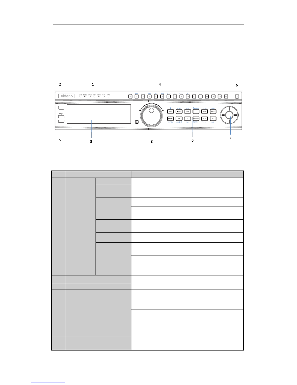
Figure 1. 1 EI-6320-NIR3
Table 1. 1 Description of Control Panel Buttons
No.
Name
Function Description
1
Status
Indicators
ALARM
Turns red when a sensor alarm is detected.
READY
Ready indicator is normally blue, indicating that the device is
functioning properly.
STATUS
Turns blue when device is controlled by an IR remote.
Turns red when controlled by a keyboard and purple when IR
remote and keyboard is used at the same time.
HDD
Blinks red when data is being read from or written to HDD.
MODEM
Reserved for future usage.
TX/RX
Blinks blue when network connection is functioning properly.
GUARD
Guard indicator turns blue when the device is in armed status; at
this time, an alarm is enabled when an event is detected.
The indicator turns off when the device is unarmed. The
arm/disarm status can be changed by pressing and holding on the
ESC button for more than 3 seconds in live view mode.
2
IR Receiver
Receiver for IR remote
3
DVD-R/W
Slot for DVD-R/W.
4
Alphanumeric Buttons
Switch to the corresponding channel in Live view or PTZ
Control mode.
Input numbers and characters in Edit mode.
Switch between different channels in Playback mode.
The light of the button is blue when the corresponding channel is
recording; it is red when the channel is in network transmission
status; it is pink when the channel is recording and transmitting.
5
USB Interfaces
Universal Serial Bus (USB) ports for additional devices such as
USB mouse and USB Hard Disk Drive (HDD).

User Manual of Network Video Recorder
12
No.
Name
Function Description
6
Composite
Keys
ESC
Back to the previous menu.
Press for Arming/disarming the device in Live View mode.
REC/SHOT
Enter the Manual Record setting menu.
In PTZ control settings, press the button and then you can call a
PTZ preset by pressing Numeric button.
It is also used to turn audio on/off in the Playback mode.
PLAY/AUTO
The button is used to enter the Playback mode.
It is also used to auto scan in the PTZ Control menu.
ZOOM+
Zoom in the PTZ camera in the PTZ Control setting.
A/FOCUS+
Adjust focus in the PTZ Control menu.
It is also used to switch between input methods (upper and
lowercase alphabet, symbols and numeric input).
EDIT/IRIS+
Edit text fields. When editing text fields, it will also function as a
Backspace button to delete the character in front of the cursor.
On checkbox fields, pressing the button will tick the checkbox.
In PTZ Control mode, the button adjusts the iris of the camera.
In Playback mode, it can be used to generate video clips for
backup.
Enter/exit the folder of USB device and eSATA HDD.
MAIN/SPOT/ZOO
M-
Switch between main and spot output.
In PTZ Control mode, it can be used to zoom out the image.
F1/ LIGHT
Select all items on the list when used in a list field.
In PTZ Control mode, it will turn on/off PTZ light (if
applicable).
In Playback mode, it is used to switch between play and reverse
play.
F2/ AUX
Cycle through tab pages.
In synchronous playback mode, it is used to switch between
channels.
MENU/WIPER
Press the button will help you return to the Main menu (after
successful login).
Press and hold the button for 5 seconds will turn off audible key
beep.
In PTZ Control mode, the MENU/WIPER button will start wiper
(if applicable).
In Playback mode, it is used to show/hide the control interface.
PREV/FOCUS-
Switch between single screen and multi-screen mode.
In PTZ Control mode, it is used to adjust the focus in
conjunction with the A/FOCUS+ button.
PTZ/IRIS-
Enter the PTZ Control mode.
In the PTZ Control mode, it is used to adjust the iris of the PTZ
camera.
7
Control
Buttons
DIRECTION
The DIRECTION buttons are used to navigate between different
fields and items in menus.
User Manual of Network Video Recorder
13
No.
Name
Function Description
In the Playback mode, the Up and Down button is used to speed
up and slow down recorded video. The Left and Right button
will select the next and previous record files.
In Live View mode, these buttons can be used to cycle through
channels.
In PTZ control mode, it can control the movement of the PTZ
camera.
ENTER
The ENTER button is used to confirm selection in any of the
menu modes.
It can also be used to tick checkbox fields.
In Playback mode, it can be used to play or pause the video.
In single-frame Playback mode, pressing the button will advance
the video by a single frame.
In Auto-switch mode, it can be used to stop /start auto switch.
8
JOG SHUTTLE Control
Move the active selection in a menu. It will move the selection
up and down.
In Live View mode, it can be used to cycle through different
channels.
In the Playback mode: The ring is used to jump 30s
forward/backward in video files.
In PTZ control mode, it can control the movement of the PTZ
camera.
9
POWER ON/OFF
Power on/off switch.
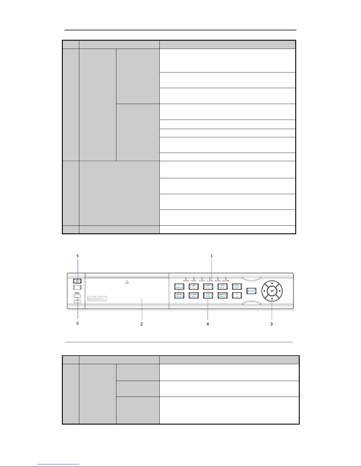
Figure 1. 2 EI-6120 NIP-16
Table 1. 2 Description of Control Panel Buttons
No.
Name
Function Description
1
Status
Indicators
POWER
Turns green when NVR is powered up.
READY
The indicator is green when the device is running normally.
STATUS
The light is green when the IR remote control is enabled;
The light is red when the function of the composite keys (SHIFT)
are used;

User Manual of Network Video Recorder
14
No.
Name
Function Description
The light is out when none of the above condition is met.
ALARM
The light is red when there is an alarm occurring.
HDD
Blinks red when HDD is reading/writing.
Tx/Rx
Blinks green when network connection is functioning normally.
2
DVD-R/W
Slot for DVD-R/W.
3
Control
Buttons
DIRECTION
In menu mode, the direction buttons are used to navigate between
different fields and items and select setting parameters.
In playback mode, the Up and Down buttons are used to speed up
and slow down record playing, and the Left and Right buttons are
used to move the recording 30s forwards or backwards.
In the image setting interface, the up and down button can adjust
the level bar of the image parameters.
In live view mode, these buttons can be used to switch channels.
ENTER
The Enter button is used to confirm selection in menu mode; or
used to check checkbox fields and ON/OFF switch.
In playback mode, it can be used to play or pause the video.
In single-frame play mode, pressing the Enter button will play the
video by a single frame.
In auto sequence view mode, the buttons can be used to pause or
resume auto sequence.
4
Composite
Keys
SHIFT
Switch between the numeric or letter input and functions of the
composite keys. (Input letter or numbers when the light is out;
Realize functions when the light is red.)
1/MENU
Enter numeral “1”;
Access the main menu interface.
2/ABC/F1
Enter numeral “2”;
Enter letters “ABC”;
The F1 button when used in a list field will select all items in the
list.
In PTZ Control mode, it will turn on/off PTZ light and when the
image is zoomed in, the key is used to zoom out.
3/DEF/F2
Enter numeral “3”;
Enter letters “DEF”;
The F2 button is used to change the tab pages.
In PTZ control mode, it zooms in the image.
4/GHI/ESC
Enter numeral “4”;
Enter letters “GHI”;
Exit and back to the previous menu.
5/JKL/EDIT
Enter numeral “5”;
Enter letters “JKL”;
Delete characters before cursor;

User Manual of Network Video Recorder
15
No.
Name
Function Description
Check the checkbox and select the ON/OFF switch;
Start/stop record clipping in playback.
6/MNO/PLAY
Enter numeral “6”;
Enter letters “MNO”;
Playback, for direct access to playback interface.
7/PQRS/REC
Enter numeral “7”;
Enter letters “PQRS”;
Open the manual record interface.
8/TUV/PTZ
Enter numeral “8”;
Enter letters “TUV”;
Access PTZ control interface.
9/WXYZ/PRE
V
Enter numeral “9”;
Enter letters “WXYZ”;
Multi-channel display in live view.
0/A
Enter numeral “0”;
Shift the input methods in the editing text field. (Upper and
lowercase, alphabet, symbols or numeric input).
Double press the button to switch the main and auxiliary output.
5
POWER ON/OFF
Power on/off switch.
6
USB Interfaces
Universal Serial Bus (USB) ports for additional devices such as
USB mouse and USB Hard Disk Drive (HDD).
User Manual of Network Video Recorder
16
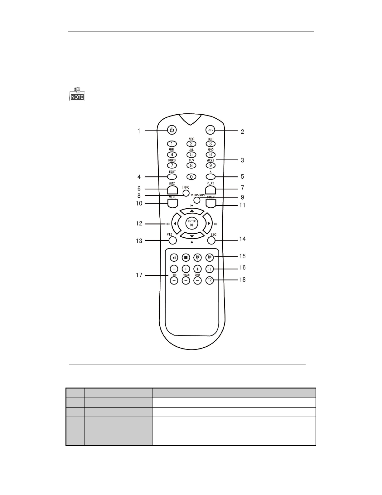
1.1 IR Remote Control Operations
The NVR may also be controlled with the included IR remote control, shown in Figure 1. 3.
Batteries (2×AAA) must be installed before operation.
Figure 1. 3 Remote Control
The keys on the remote control closely resemble the ones on the front panel. See Table 1. 3.
Table 1. 3 Description of the Soft Keyboard Icons
No.
Name
Description
1
POWER
Power on/off the device.
2
DEV
Enables/Disables Remote Control.
3
Alphanumeric Buttons
Same as Alphanumeric buttons on front panel.
4
EDIT Button
Same as EDIT/IRIS+ button on front panel.
5
A Button
Same as A/FOCUS+ button on front panel.

User Manual of Network Video Recorder
17
No.
Name
Description
6
REC Button
Same as REC/SHOT button on front panel.
7
PLAY Button
Same as the PLAY/AUTO button on front panel.
8
INFO Button
Reserved.
9
VOIP/MON Button
Same as the MAIN/SPOT/ZOOM- button on front panel.
10
MENU Button
Same as the MENU/WIPER button on front panel.
11
PREV Button
Same as the PREV/FOCUS- button on front panel.
12
DIRECTION/ENTER
Buttons
Same as the DIRECTION/ENTER buttons on front panel.
13
PTZ Button
Same as the PTZ/IRIS- button on front panel.
14
ESC Button
Same as the ESC button on front panel.
15
RESERVED
Reserved for future usage.
16
F1 Button
Same as the F1/LIGHT button on front panel.
17
PTZ Control Buttons
Buttons to adjust the iris, focus and zoom of a PTZ camera.
18
F2 Button
Same as the F2/AUX button on front panel.
Troubleshooting Remote Control:
Make sure you have installed batteries properly in the remote control. And you have to aim the remote
control at the IR receiver in the front panel.
If there is no response after you press any button on the remote, follow the procedure below to troubleshoot.
Steps:
1. Go to Menu > Settings > General > More Settings by operating the front control panel or the mouse.
2. Check and remember NVR ID#. The default ID# is 255. This ID# is valid for all the IR remote controls.
3. Press the DEV button on the remote control.
4. Enter the NVR ID# you set in step 2.
5. Press the ENTER button on the remote.
If the Status indicator on the front panel turns blue, the remote control is operating properly. If the Status indicator
does not turn blue and there is still no response from the remote, please check the following:
1. Batteries are installed correctly and the polarities of the batteries are not reversed.
2. Batteries are fresh and not out of charge.
3. IR receiver is not obstructed.
If the remote still can’t function properly, please change a remote and try again, or contact the device provider.

User Manual of Network Video Recorder
18
1.2 USB Mouse Operation
A regular 3-button (Left/Right/Scroll-wheel) USB mouse can also be used with this NVR. To use a USB mouse:
1. Plug USB mouse into one of the USB interfaces on the front panel of the NVR.
2. The mouse should automatically be detected. If in a rare case that the mouse is not detected, the possible
reason may be that the two devices are not compatible, please refer to the recommended the device list
from your provider.
The operation of the mouse:
Table 1. 4 Description of the Mouse Control
Name
Action
Description
Left-Click
Single-Click
Live view: Select channel and show the quick set menu.
Menu: Select and enter.
Double-Click
Live view: Switch between single-screen and multi-screen.
Click and Drag
PTZ control: pan, tilt and zoom.
Video tampering, privacy mask and motion detection: Select target area.
Digital zoom-in: Drag and select target area.
Live view: Drag channel/time bar.
Right-Click
Single-Click
Live view: Show menu.
Menu: Exit current menu to upper level menu.
Scroll-Wheel
Scrolling up
Live view: Previous screen.
Menu: Previous item.
Scrolling down
Live view: Next screen.
Menu: Next item.
User Manual of Network Video Recorder
19
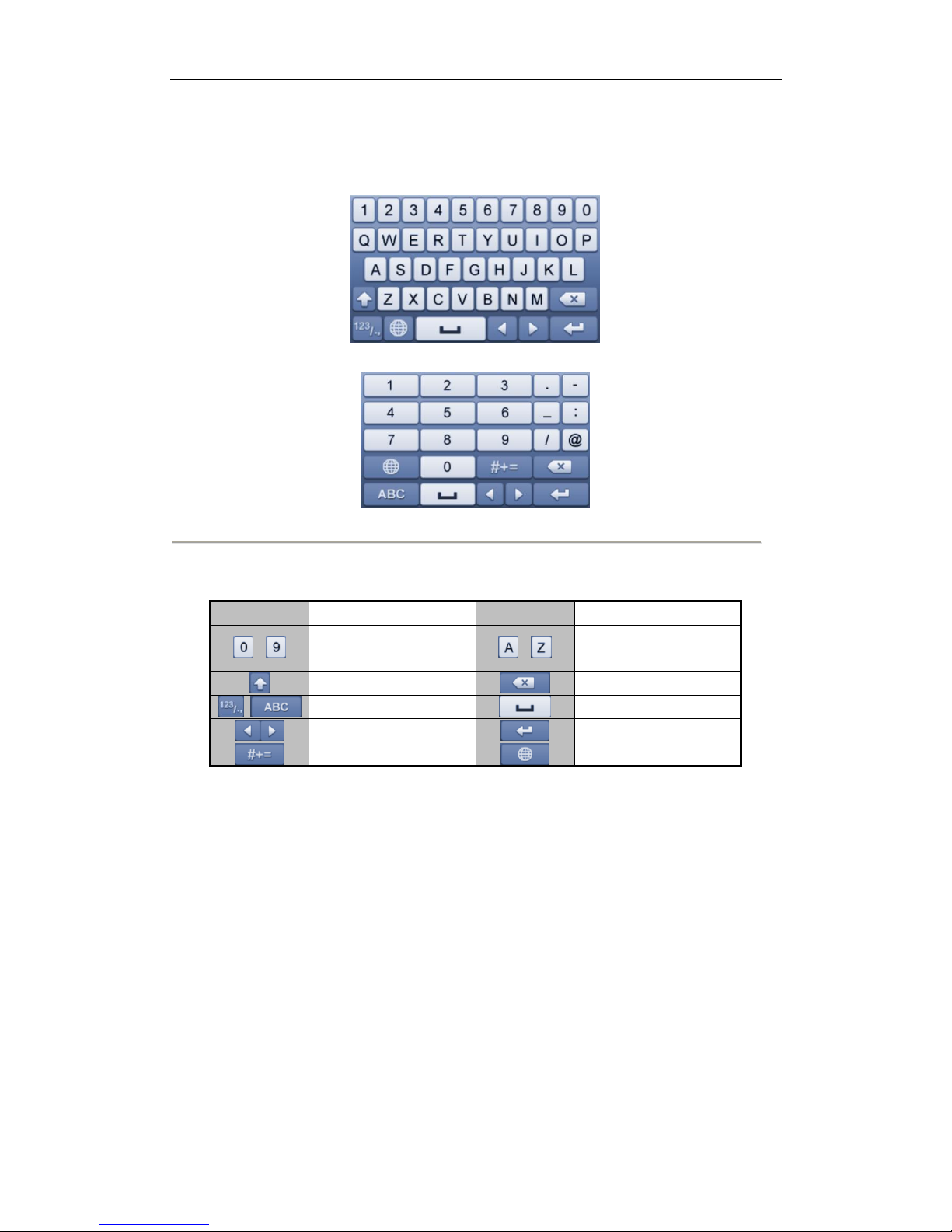
1.3 Input Method Description
Figure 1. 4 Soft Keyboard (1)
Figure 1. 5 Soft Keyboard (2)
Description of the buttons on the soft keyboard:
Table 1. 5 Description of the Soft Keyboard Icons
Icon
Description
Icon
Description
…
Number
…
English letter
Lowercase/Uppercase
Backspace
Switch the keyboard
Space
Positioning the cursor
Exit
Symbols
Reserved
User Manual of Network Video Recorder
20
1.4 Rear Panel
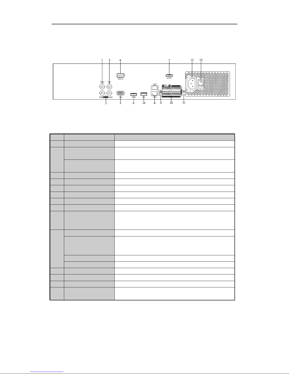
Figure 1. 6 EI-6320-NIR3
Table 1. 6 Description of Rear Panel Interfaces
No.
Item
Description
1
VIDEO OUT
BNC connector for video output.
2
CVBS AUDIO OUT
BNC connector for audio output. This connector is synchronized with
CVBS video output.
VGA AUDIO OUT
BNC connector for audio output. This connector is synchronized with
VGA video output.
3
LINE IN
BNC connector for audio input.
4
RS-232 Interface
Connector for RS-232 devices.
5
VGA
DB9 connector for VGA output. Display local video output and menu.
6
HDMI
HDMI video output connector.
7
eSATA (Optional)
Connects external SATA HDD, CD/DVD-RM.
8
Network Interface
1 network interface
9
Termination Switch
RS-485 termination switch.
Up position is not terminated.
Down position is terminated with 120Ω resistance.
10
RS-485 Interface
Connector for RS-485 devices.
Controller Port
D+, D- pin connects to Ta, Tb pin of controller. For cascading devices,
the first NVR’s D+, D- pin should be connected with the D+, D- pin of
the next NVR.
ALARM IN
Connector for alarm input.
ALARM OUT
Connector for alarm output.
11
GROUND
Ground (needs to be connected when NVR starts up).
12
AC 100V ~ 240V
AC 100V ~ 240V power supply.
13
POWER
Switch for turning on/off the device.
14
USB interface
Universal Serial Bus (USB) ports for additional devices such as USB
mouse and USB Hard Disk Drive (HDD).
User Manual of Network Video Recorder
21
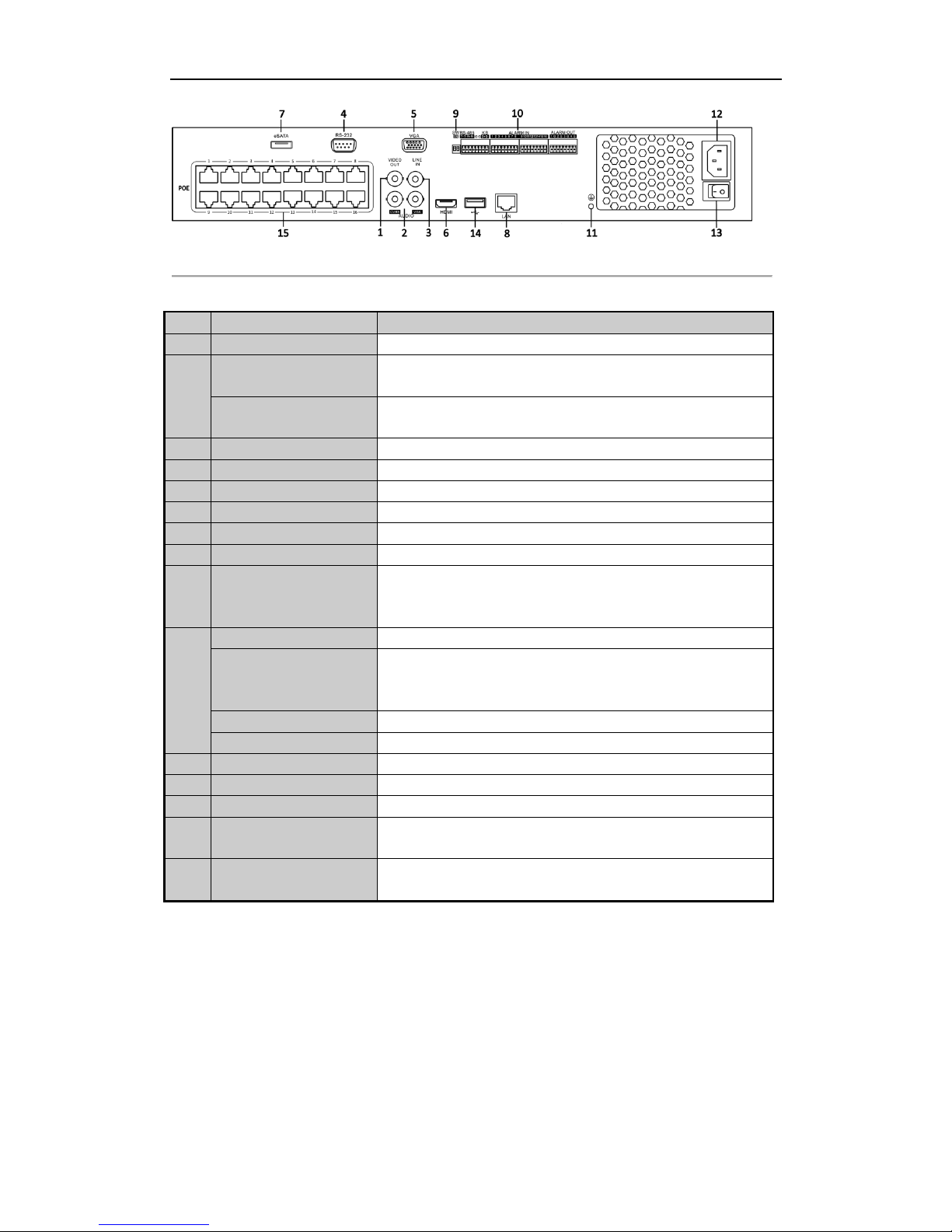
Figure 1. 7 EI-6120 NIP-16
Table 1. 7 Description of Rear Panel Interfaces
No.
Item
Description
1
VIDEO OUT
BNC connector for video output.
2
CVBS AUDIO OUT
BNC connector for audio output. This connector is synchronized with
CVBS video output.
VGA AUDIO OUT
BNC connector for audio output. This connector is synchronized with
VGA video output.
3
LINE IN
BNC connector for audio input.
4
RS-232 Interface
Connector for RS-232 devices.
5
VGA
DB9 connector for VGA output. Display local video output and menu.
6
HDMI
HDMI video output connector.
7
eSATA (Optional)
Connects external SATA HDD, CD/DVD-RM.
8
Network Interface
1 network interface
9
Termination Switch
RS-485 termination switch.
Up position is not terminated.
Down position is terminated with 120Ω resistance.
10
RS-485 Interface
Connector for RS-485 devices.
Controller Port
D+, D- pin connects to Ta, Tb pin of controller. For cascading devices,
the first NVR’s D+, D- pin should be connected with the D+, D- pin of
the next NVR.
ALARM IN
Connector for alarm input.
ALARM OUT
Connector for alarm output.
11
GROUND
Ground (needs to be connected when NVR starts up).
12
AC 100V ~ 240V
AC 100V ~ 240V power supply.
13
POWER
Switch for turning on/off the device.
14
USB interface
Universal Serial Bus (USB) ports for additional devices such as USB
mouse and USB Hard Disk Drive (HDD).
15
Network Interfaces with
PoE function
Network interface for the cameras and to provide power over Ethernet.

User Manual of Network Video Recorder
22
Chapter 2 Getting Started
2.1 Starting Up and Shutting Down the NVR
Purpose:
Proper startup and shutdown procedures are crucial to expanding the life of the NVR.
Before you start:
Check that the voltage of the extra power supply is the same with the NVR’s requirement, and the ground
connection is working properly.
Starting up the NVR:
Steps:
1. Check the power supply is plugged into an electrical outlet. It is HIGHLY recommended that an
Uninterruptible Power Supply (UPS) be used in conjunction with the device. The Power indicator LED on
the front panel should be red, indicating the device gets the power supply.
2. Press the POWER button on the front panel. The Power indicator LED should turn blue indicating that the
unit begins to start up.
3. After startup, the Power indicator LED remains blue. A splash screen with the status of the HDD appears on
the monitor. The row of icons at the bottom of the screen shows the HDD status. ‘X’ means that the HDD
is not installed or cannot be detected.
Shutting down the NVR
Steps:
There are two proper ways to shut down the NVR.
OPTION 1: Standard shutdown
1. Enter the Shutdown menu.
Menu > Shutdown
Figure 2. 1 Shutdown Menu
2. Click the Shutdown button.
3. Click the Yes button.
OPTION 2: By operating the front panel
1. Press and hold the POWER button on the front panel for 3 seconds.
2. Enter the administrator’s username and password in the dialog box for authentication.
3. Click the Yes button.

User Manual of Network Video Recorder
23
Do not press the POWER button again when the system is shutting down.
Rebooting the NVR
In the Shutdown menu, you can also reboot the NVR.
Steps:
1. Enter the Shutdown menu by clicking Menu > Shutdown.
2. Click the Logout button to lock the NVR or the Reboot button to reboot the NVR.
User Manual of Network Video Recorder
24
2.2 Using the Wizard for Basic Configuration
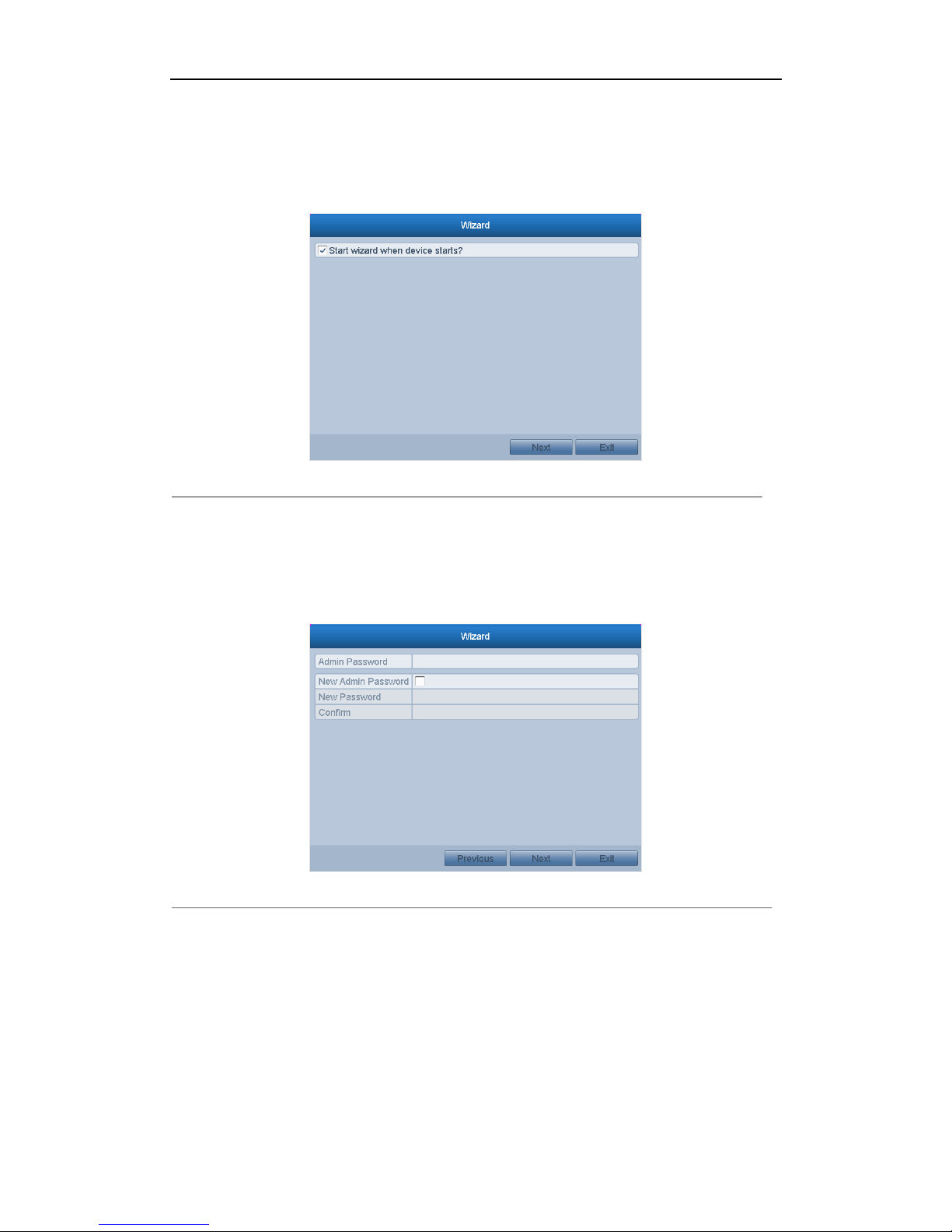
By default, the Setup Wizard starts once the NVR has loaded, as shown in Figure 2. 2.
Figure 2. 2 Start Wizard Interface
Operating the Setup Wizard:
1. The Setup Wizard can walk you through some important settings of the NVR. If you don’t want to use the
Setup Wizard at that moment, click the Cancel button. You can also choose to use the Setup Wizard next
time by leaving the “Start wizard when the device starts?” checkbox checked.
2. Click Next button on the Wizard window to enter the Login window, as shown in Figure 2. 3.
Figure 2. 3 Login Window
3. Enter the admin password. By default, the password is 12345.
4. To change the admin password, check the New Admin Password checkbox. Enter the new password and
confirm the password in the given fields.
5. Click the Next button to enter the date and time settings window, as shown in Figure 2. 4.
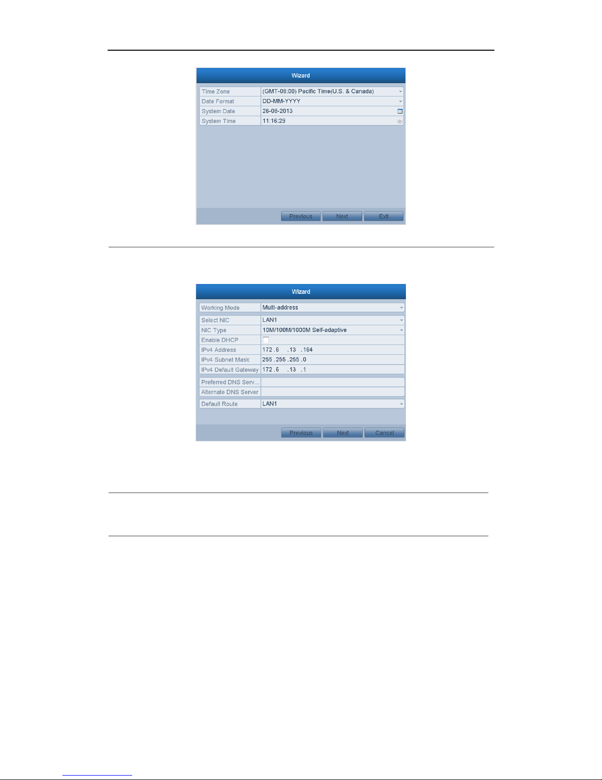
User Manual of Network Video Recorder
25
Figure 2. 4 Date and Time Settings
6. After the time settings, click Next button which takes you back to the Network Setup Wizard window, as
shown in Figure 2. 5.
EI-6320-NIR3
Figure 2. 5 Network Configuration
7. Click Next button after you configured the network parameters, which takes you to the HDD Management
window, shown in Figure 2. 6.
User Manual of Network Video Recorder
26
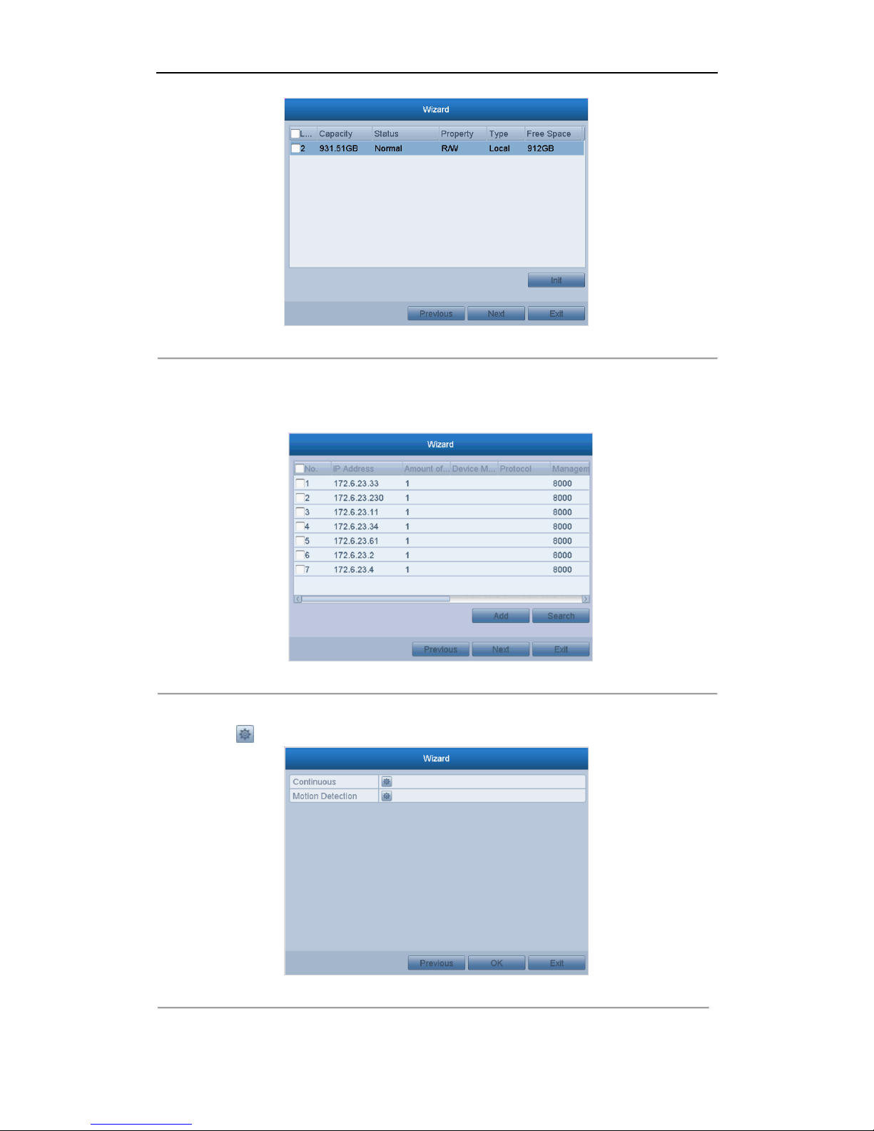
Figure 2. 6 HDD Management
8. To initialize the HDD, click the Init button. Initialization removes all the data saved in the HDD.
9. Click Next button. You enter the Adding IP Camera interface.
10. Click Search to find online IP Camera. Select the IP camera to be added, and click the Add button.
Figure 2. 7 Search for IP Cameras
11. Click Next button. Configure the recording for the searched IP Cameras.
Click the icon to start the selected typr of recording for all channels.
Figure 2. 8 Record Settings

User Manual of Network Video Recorder
27
12. Click OK to complete the startup Setup Wizard.
User Manual of Network Video Recorder
28
2.3 Adding and Connecting the IP Cameras
2.3.1 Adding the Online IP Cameras
Purpose:
The main function of the NVR is to connect the network cameras and record the video got from it. So before you
can get a live view or record of the video, you should add the network cameras to the connection list of the device.
Before you start:
Ensure the network connection is valid and correct. For detailed checking and configuring of the network, please
see Chapter Checking Network Traffic and Chapter Configuring Network Detection.
OPTION 1:
Steps:
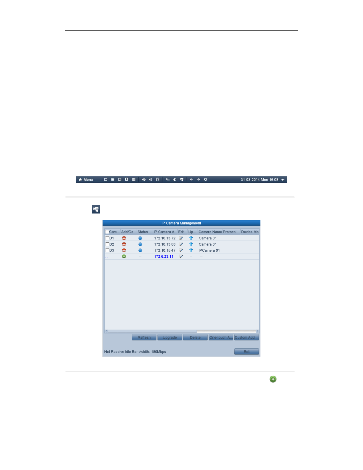
1. Right-click the mouse when you in the live view mode to show the right-click menu.
Figure 2. 9 Right-click Menu
2. Select in the pop-up menu to enter the IP Camera Management interface.
Figure 2. 10 Adding IP Camera Interface
3. The online cameras with same network segment will be displayed in the camera list. Click the button to
add the camera.
Or you can click the One-touch Adding button to add all the online IP cameras.
User Manual of Network Video Recorder
29
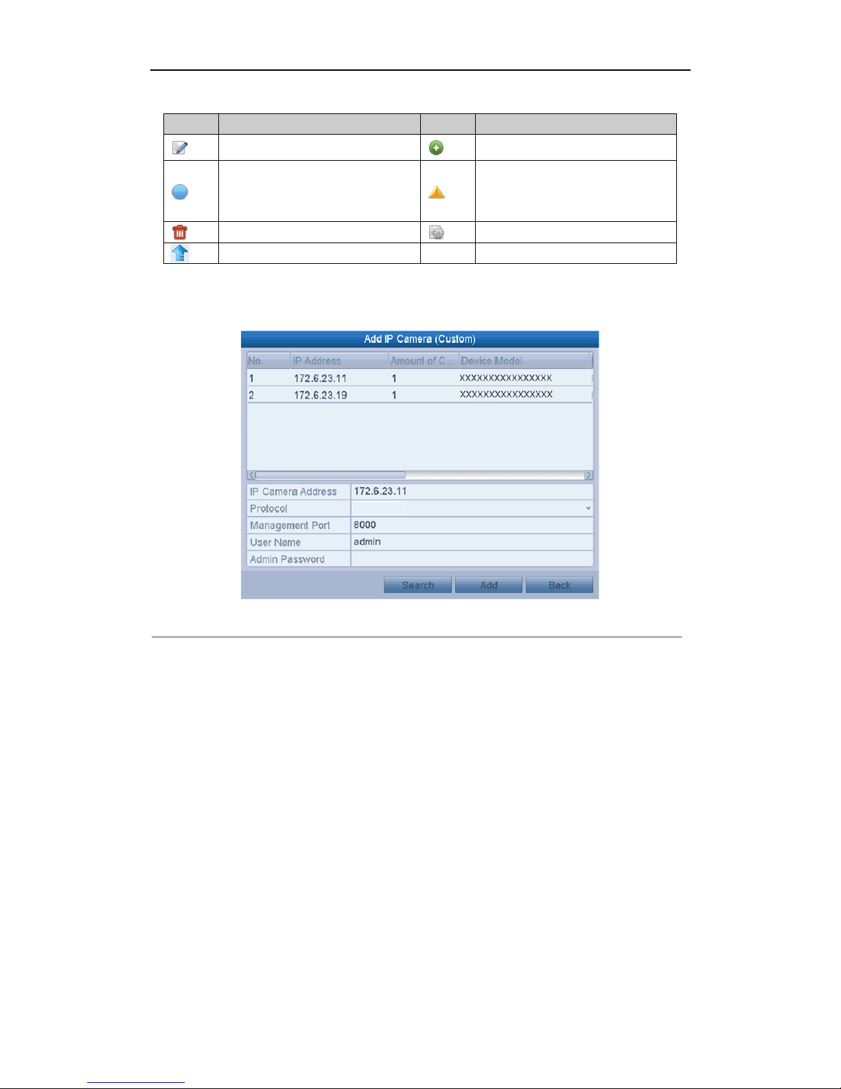
Table 2. 1 Explanation of the icons
Icon
Explanation
Icon
Explanation
Edit basic parameters of the camera
Add the detected IP camera.
The camera is connected.
The camera is disconnected; you can
click the icon to get the exception
information of camera.
Delete the IP camera
Advanced settings of the camera.
Upgrade the added IP camera.
4. To add other IP cameras:
1) Click the Custom Adding button to pop up the Add IP Camera (Custom) interface.
Figure 2. 11 Custom Adding IP Camera Interface
2) You can edit the IP address, protocol, management port, and other information of the IP camera to be
added.
3) Click Add to add the camera.
OPTION 2:
Steps:
1. Enter the Camera Management interface.
Menu> Camera> Camera
 Loading...