

Eicom HTEC-500 User Manual

HPLC-ECD Stand Alone System
(H
TEC-500)
AC01-0319
User’s Guide
Eicom Corporation

Contents
1. Important Checklist Before Operation ............................................. 1
2. Terminology .......................................................................................... 2
3. A List of Fitting Parts and Directions for Use...................................... 3
4. Mobile Phase Preparation.................................................................. 4
5. System Installation ............................................................................... 5
5-1. Wiring.......................................................................................... 5
5-2. Tubing and Degasser............................................................... 5
5-3. Connecting to the Autoinjector and the Autosampler
(Plumbing) ......................................................................................... 5
5-4. Connecting to the Autoinjector and the Autosampler
(Electrical Signal Connection) ....................................................... 6
6. Online Elution Degassing System ...................................................... 7
6-1. If you think the degassing efficiency is reduced,
you may diagnose the problem by the
following procedure: .................................................... 7
7. HPLC Pump Operation ....................................................................... 8
7-1. Run/Stop .................................................................................... 9
7-2. Flow Rate Setting...................................................................... 9
7-3. Pulse Free Mode Setting.......................................................... 10
7-4. Function of Pulse Free Mode .................................................. 10
8. How to Fix Pump Errors and Problems ..............................................11
8-1. Less Flow Rate, Less Pump Pressure or
Unstable Pump Pressure ............................................... 11
8-2. Types of Pump Errors ................................................................ 12
8-3. How to Fix these Errors.............................................................. 13

9. Manual Sample Injector and Autoinjector...................................... 16
9-1. Structure..................................................................................... 16
9-2. Operation of Manual Injector ................................................ 16
9-3. Autosampler and Autoinjector Setup ................................... 17
10. Precolumn ............................................................................................ 18
10-1. Types of Precolumn Housing and Line Filters........................ 18
10-2. Identification of Precolumn Quality....................................... 19
10-3. How to Repack ......................................................................... 20
10-4. Filter Exchange ......................................................................... 21
11. ECD Operation..................................................................................... 22
11-1. Basics.......................................................................................... 22
11-2. Working Electrode.................................................................... 23
11-3. Applied Potential...................................................................... 23
11-4. Time Constant ........................................................................... 25
11-5. Background Current ................................................................ 25
11-6. If Background Current is High ................................................. 25
11-7. Caution for the Platinum Working Electrode........................ 25
12. Storage of the System ......................................................................... 26
12-1. Short-term (A few days to a few weeks) ................................................26
12-2. Long-term (more than a few days or a few weeks) ............................26
13. Storage of a Standard Sample ......................................................... 27
14. Regular Maintenance Schedule....................................................... 28
Daily Maintenance.............................................................................. 28
Occasional Maintenance.................................................................. 28
Yearly Maintenance ........................................................................... 28
15. Troubleshooting ................................................................................... 30
Appendix. A ................................................................................................... 33

This page intentionally left blank.
HTEC-500
1. Important Checklist Before Operation
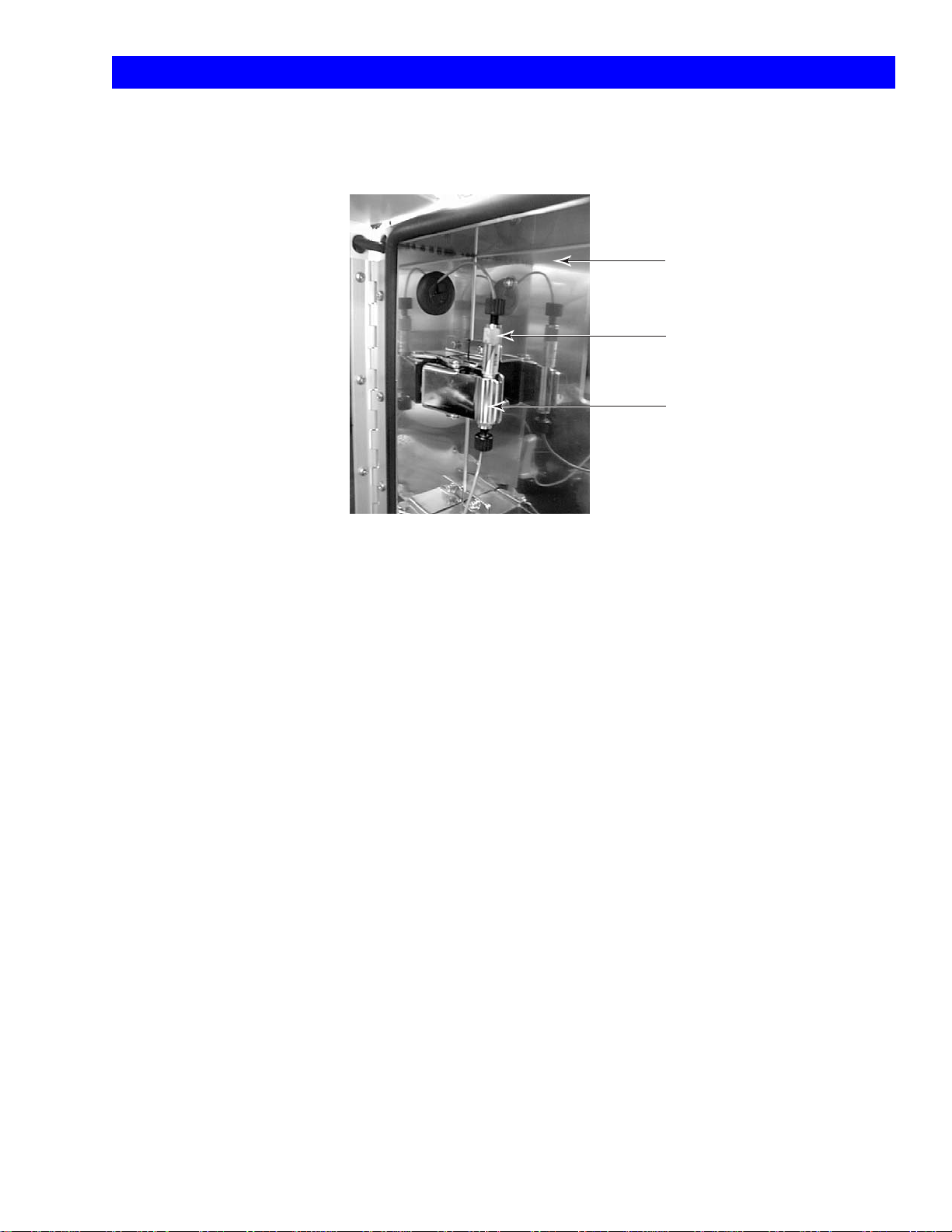
• The separation column and the enzyme column must be held firmly by the column clip. The stainless
steel surfaces should make good contact with each other in order to ground static electricity. This
may be the cause of noise in the ECD.
Door
Separation Column (PP-ODS)
Column Clip
Fig. 1 Separation Column Installation
A separation column must be held firmly by the column clip.
When an enzyme column is used, the enzyme column must
also be held firmly by the column clip. The respective stainless
steel surfaces should make good contact in order to ground
static electricity. This can be the cause of noise in the ECD.
• Place the mobile phase container and the waste container on the same level as the HTEC-500.
• Use glass bottles as mobile phase and ultrapure water containers. Do not use any plastic containers.
• Rinse behind the pump pistons with ultrapure water before and after use through the pump piston
washing port. Do not use any organic solvents in the rinse solution. If precipitation or something blocks
the line, do not push out with high pressure or force. First, disconnect the line and then remove the
source of the blocking.
• Before opening the detector cell for maintenance, remove the outlet screw and aspirate all the
remaining mobile phase in the detector cell with a syringe.
• Pay attention to prevent any tubing from becoming blocked. Salt solvents must be rinsed out by
ultrapure water before an organic solvent of a high concentration is used. Drying out of the salt
solvent should also be avoided.
• Pay attention not to allow any leakage from any connection points of the tubing. Leakage is not only
harmful for the equipment but also generates pump pulse noise.
• When air is thought to be present in the tubing or the pump, please purge the air (see chapter 8,
page 11). Then you can connect a column.
• Pulse free mode must be switched on during the analysis.
1
HTEC-500
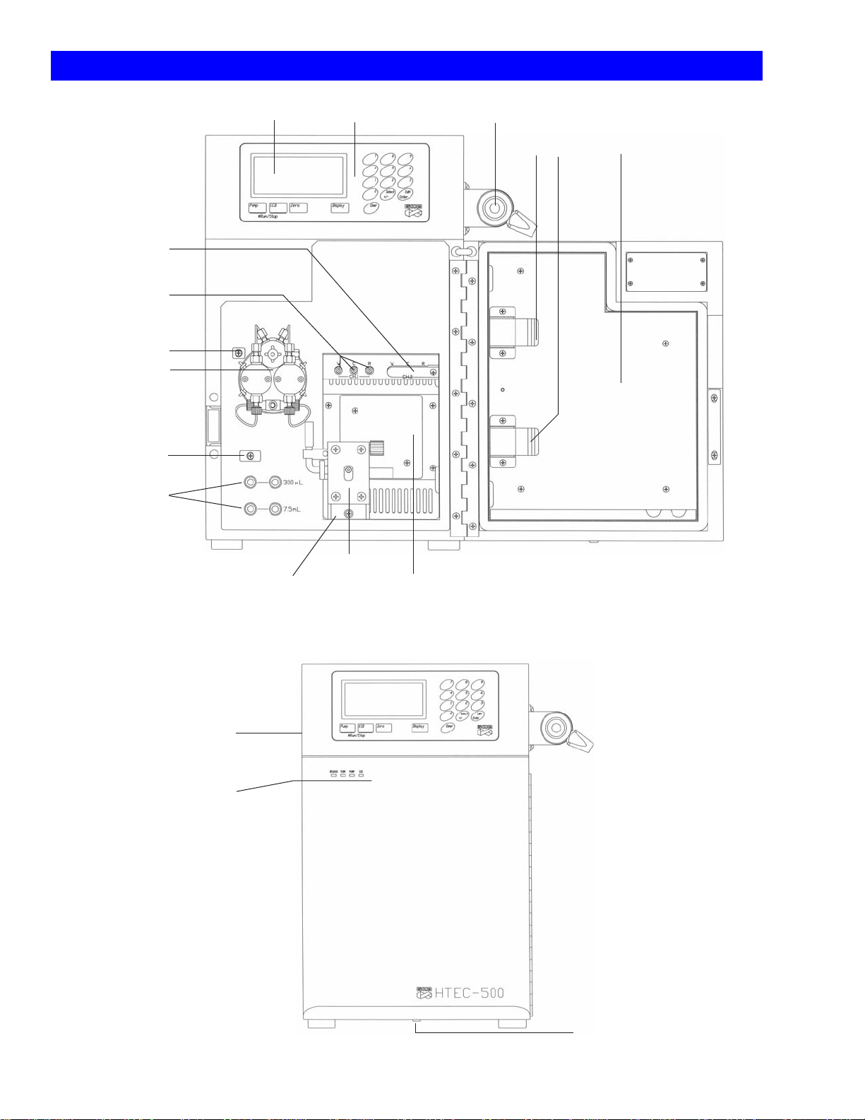
2. Terminology
Terminal Ch2
(for PEC-510)
ECD Terminal Ch1
Tubing Guide
HPLC Pump
(See Fig. 7)
Tubing Guide
Online Elution
Degasser
Display Manual Injector
Control Panel
Column Clips
Door Cabinet
Main Power Switch
(Back Side)
Status Indicator
ECD Cell
Cell Mount
Thermo Controller
Fig. 2 HTEC-500 Front View (Door open)
Cabinet Drain
Fig. 3 HTEC-500 Front View (Door closed)
2
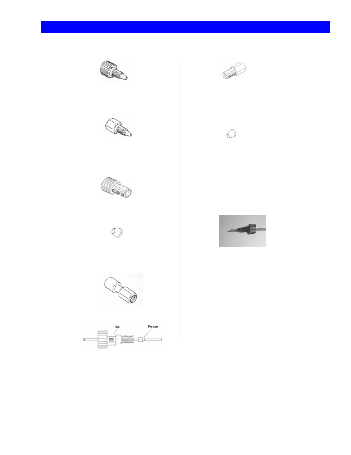
3. A List of Fitting Parts and Directions for Use
HTEC-500
Tough Connector
Low pressure part. For column connections.
Hex Nut
High pressure part (pumps)
Flat Seal Nut
Flat Seal for Degasser
The wide side is for the degasser and
narrow side is for the nut.
Two-way Joint
Nut for Inlet of Cell
Ferrule for Inlet of Cell
The narrow side is for the cell and
the wide side is for the nut.
Tubing connection
Connect the tubing and keep its tip sticking out of the ferrule
(as seen above), except for the connection with the degasser
which uses a flat seal. First, put the tubing through the ferrule
and put its tip into the holder. Then connect it by tightening
the screw. The connecting part should be sealed by a cross
section of the tubing and the holder of the tubing. For the
injector connection, use the nuts and ferrules for its connection
only. The slit side is for the nut (see figure).
Rheodyne PEEK nut
Pheodyne PEEK Ferrule
(For Injector)
Fig. 4 Tubing Connection Parts and Directions for Use
3

HTEC-500
4. Mobile Phase Preparation
Prepare the mobile phase according to the Eicom technical information. The mobile phase preparation
depends on what you are measuring with the HTEC-500. Please read below to find a general method
for mobile phase preparation. Also, the following points should be noted because the ECD has a higher
sensitivity compared to other detectors:
• Use ultrapure water (the resistance of the water needs to be at least 18.2 mega-ohm/cm). Any
solvent, such as mobile phase, or water applied to this system should be stored in a glass bottle.
• Use glass instruments for the preparation of mobile phase. Before use, these instruments should be
rinsed out by water and then by ultrapure water.
• Use reagents of super grade or HPLC grade quality. The following are our recommendations: for
sodium 1-Octanesulfonate, use Nacalai (code 3179-62, available at Eicom); for sodium
1-Decanesulfonate, use TCI (code I-0348 available at VWR); and for EDTA-2Na use Dojindo
(code 372.24). Separation patterns or ECD can be influenced by the use of other reagents.
• Methanol and buffer solution/water must be measured separately and then mixed. Otherwise the
methanol concentration will be higher than the designated level due to the solubility of methanol in
water.
• Do not use a sonicator for dissolving salts in the mobile phase. This may raise the background current
of the ECD.
• When all reagents are added, plug the bottle and shake and mix it thoroughly. Check if all reagents
are dissolved.
• Filtration is good for removing unwanted particles but can be a source of chemical contamination.
We do NOT recommend you to filter the mobile phase but rather encourage you to avoid any
contamination during the preparation of the mobile phase. Using less glassware and always putting a
cap or cover on the top of the containers helps to reduce chances of contamination. If you must filter
the mobile phase, use a chemically clean apparatus and do not store the mobile phase in plastic
bottles after the filtration.
• A filter at the end of the inlet tubing placed in the mobile phase can also be a cause of chemical
contamination or bacterial growth. Eicom does not recommend you to use these type of filters. If you
need to use one, please replace the filter frequently and keep it clean. Instead of these filters, we
recommend you to set a precolumn before the separation column. (If using the PP-ODS column,
please use in-line filter #PP-LF, before the precolumn and put a precolumn before the injectors.) The
precolumn filter after the HPLC pump does not prevent contamination of the HPLC pump.
• Mobile phase can only be used for one week from the date of opening/preparation. Bottles should
be well sealed while it is being used for HPLC. Do not add new mobile phase to the bottle of old
mobile phase. This is to avoid the breeding of various germs in the system.
4
HTEC-500
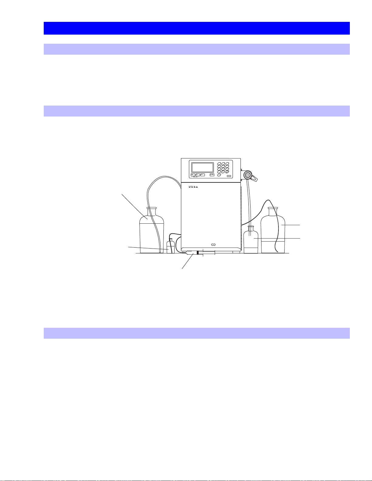
Please place the HTEC-500 on a horizontal and stable table. The mobile
phase and waste containers should be placed on the same level as the
HTEC-500.
Fig. 5 HTEC-500 Installation
HTEC-500
Mobile Phase
(Always use a glass bottle)
Pump Piston Washing
Syringe for Aspiration
Pump Piston Washing
Ultrapure Water
Mobile Phase Waste
Injector Waste
5. System Installation
5-1. Wiring
Connect the terminal adapter (orange color) to the terminal at the right side of the system. Then
connect the AC cable to the main power supply and turn on the system. “Initializing” appears on the
display, followed by the ECD controller screen. Now you can turn off the system for the next steps
described below.
5-2. Tubing and Degasser
Pull the tubing’s for the pump rinse, the mobile phase suction and the cell drain out of the HTEC-500
system. Put all the equipment on a level place. Mobile phase and waste bottles should be placed on
the same level as the HTEC-500 (See Fig. 5).
5-3. Connecting to the Autoinjector and the Autosampler (Plumbing)
Injectors of the autoinjector (online autoinjector, EAS-20) and/or the autosampler should be set up
downstream to the manual injector. For the autoinjector, connect no. 3 port of the manual injector with
no. 2 port of the autoinjector using 0.125 mm PEEK tubing (red). Then connect no. 3 port of the
autoinjector with the separation column using the same kind of tubing. For the autosampler (model
Alcott 719D or 719AL), connect no. 3 port of the manual injector with no. 2 port of the autoinjector and
no. 3 port of the autoinjector with the separation column.
5
HTEC-500
5-4. Connecting to the Autoinjector and the Autosampler
(Electrical Signal Connection)
A trigger signal needs to be sent from the online autoinjector or the autosampler to the data acquisition
unit to inform it of the injection timing. It also needs to be sent to the HTEC-500 in order to give the auto
zero signal. The auto zero works to shift the baseline to the zero level. Please connect the trigger signal
output on the autoinjector/autosampler with “signal in” of the terminal adapter located on the left side
of the HTEC-500. Please also refer to Fig. 6. There is no polarity on “signal in”. To find where the output of
the trigger signal is, please look at the user’s manual of your autoinjector/autosampler. If your
autosampler has an “emergency stop input”, please connect this terminal of the autosampler to the
pump error out on the HTEC-500 signal terminal. A non-polar contact closure signal will occur when the
pump on the HTEC-500 gives error readings (see chapter 8, page 12 for the errors). This way you can
prevent loosing samples when the HPLC pump HTEC-500 accidentally stops.
Connect to
EPC-300 (option) CH terminal
EPC-300 CTL terminal
EAS-20/Autosampler (option)
Manual injector
EPC-300 TRG
Autosampler emergency stop
Fig. 6 Electrical Connections
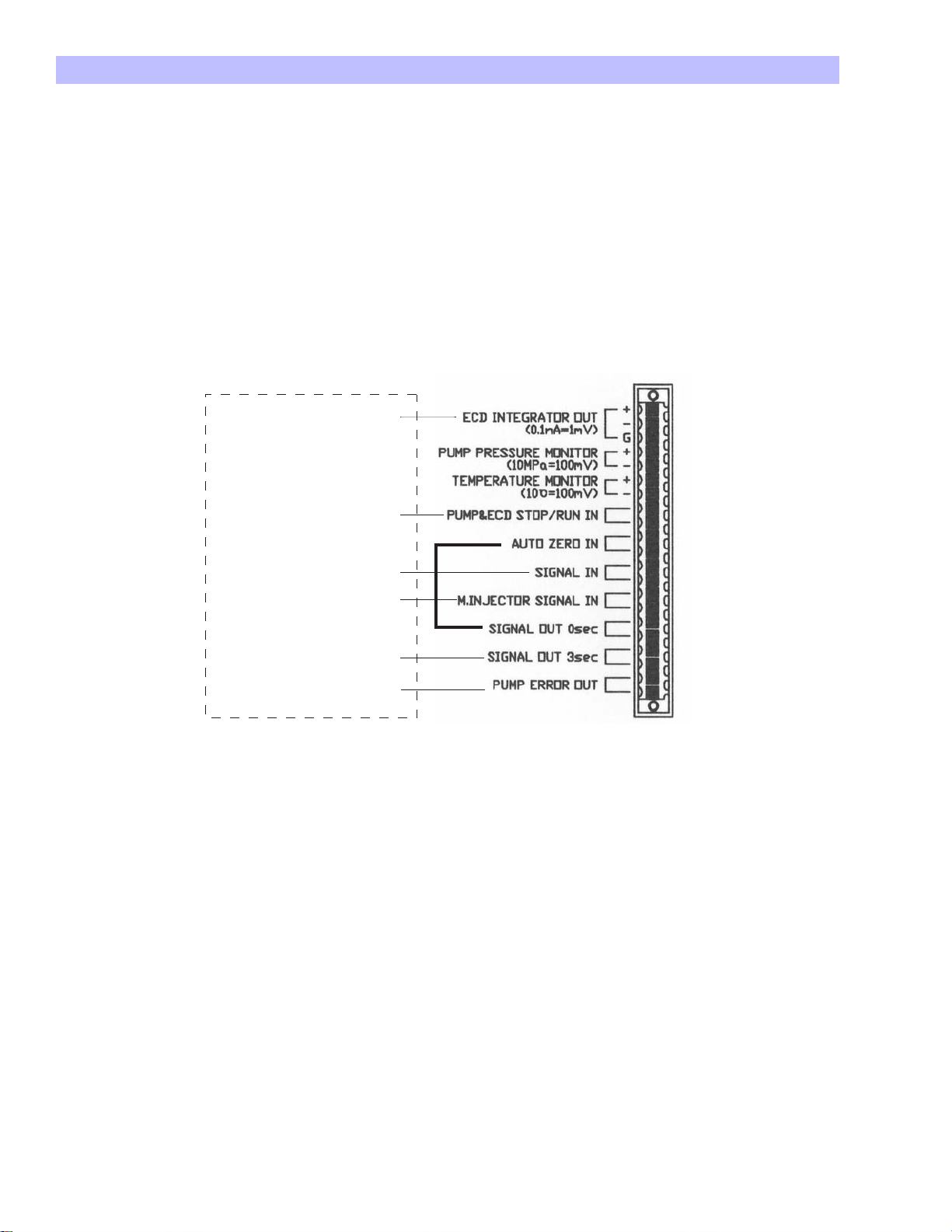
Please follow this diagram to figure out the electrical connections. The ports not showing +/- have no
polarity. AUTO ZERO and SIGNAL OUT 0sec are connected before installation. With this connection,
M.INJECTOR SIGNAL IN receives a signal when the manual injector is set to the inject position from the load
position and then SIGNAL OUT 0 sec sends a signal to AUTO ZERO IN. Through this signal, AUTO ZERO is
complete. SIGNAL OUT 3 sec sends a signal to the trigger port of the EPC-300 (not included in this system).
Through this signal, a chromatograph starts to be recorded. PUMP ERROR OUT is a signal port to stop the
auto sample injection from the auto sampler when the pump flow is not good. For more details, please
refer to the instruction manual for the auto sampler. PUMP PRESSURE and TEMPERATURE MONITOR are ports
to record operation condition of this system.
6

HTEC-500
6. Online Elution Degassing System
The degassing component works to remove dissolved air from the mobile phase. The dissolved air
occasionally interferes with the HPLC pumping or electrochemical detection. To prevent unexpected
problems with the analyses, always use the degassing system. Mobile phase goes through the system
when the pump is running and it is automatically degassed. Please note that the degassing system does
not work to remove an air segment(s) from the inlet tubing.
The degassing component consists of a bunch of polymer capillary tubings located in a vacuum
chamber. The dissolved gases in the solvent are pulled through the tubing walls by the differential
pressure. To reduce the pressure in the chamber, a vacuum pump runs intermittently and a valve opens
and closes the connection between the low pressure chamber and the vacuum pump. This valve
generates a clicking noise.
Two Channels, 300 μl and 7.5 ml
Two channels (upper and lower) are installed in the online degassing system. Either the 300 μl channel or
the 7.5 ml channel can be used. The 300 μl channel is more efficient at exchanging the liquid in the
degassing component. At a flow rate of 500 μl/min of mobile phase, the degassing efficiency is the
same between the two channels. There is no independent switch to turn on and off the degassing
system. The main power switch regulates the power of the degassing system.
6-1. If you think the degassing efficiency is reduced, you may diagnose the
problem by the following procedure:
• Replace the mobile phase at the end of the inlet tubing of the system with ultrapure water.
• Turn off the pump and use a syringe to aspirate 5 ml of mobile phase from the pump drain valve and
then close the valve. Leave the system off for 10 min. It is not necessary to remove the columns.
• Turn on the main power and listen to the degassing pump noise (not the HPLC pump). The pump is
supposed to stop in a few minutes. The pump has a function to create a vacuum chamber inside of
the degassing system to allow dissolved air to go through the tubing inside.
• If the degassing pump stops within 4.5 min, the degassing system is functional.
• If the pump works for 4.5 min continuously, the degassing system is likely to have a mechanical
problem. Please time precisely for 4 min. If the degassing pump runs for 5 min, the pump will stop
automatically to prevent overrunning regardless of whether the degassing component is working
properly or not.
7

HTEC-500
7. HPLC Pump Operation
Pay attention to the following points about the pump operation:
• Rinse behind the pump pistons with ultrapure water before and after use. Do not use any organic
solvents in the rinse solution. It is common that an air bubble or air segment may appear in the piston
wash line but it does not affect any functions.
• The mobile phase container should be a clean glass bottle. Do not use a plastic container.
• Put the mobile phase container on the same level as the HTEC-500.
PEEK Tubing 0.5 mm ID
nut
Drain
(Tubing connected to the piston wash ports is silicon 3 1 mm)
OPEN
Easy Fit
Pump Outlet
Piston Wash Port
Check Valve (Outlet)
Pump Head
Piston Wash Port
Check Valve (Inlet)
PEEK Tubing 0.75 mm ID
Fig. 7 Pump Parts and Drain
The drain valve and the drain port are integrated. Connect a syringe
to the drain port (as in the figure above) and turn the drain valve a
half circle. Use the syringe to suck out some mobile phase.
Check Valve
(Outlet)
Head Guide
Rod Assay
Pump Head
O ring
Backup Ring
Piston Seal
Check Valve (Inlet)
Piston
Wash Port
Fig. 8 Pump Details
Center Guide
Diaphagm
8
HTEC-500
7-1. Run/Stop
Use the pump key to turn the pump on and off. When the pump is running, the pump light should be on
at the front of the system. Also, *PUMP* on the liquid crystal display (LCD) indicates the pump is running,
while -PUMP- indicates the pump is off.
7-2. Flow Rate Setting
• Select the pump monitor by pushing the display key (the display key switches between the ECD and
the PUMP screen).
• Push the edit key once. ‘ ’ appears beside the flow rate (μl/min).
• Enter the adequate number from 1 to 750 using the 10 number keys.
• Push the edit key once more. ‘ ’ should now be beside pulse free mode.
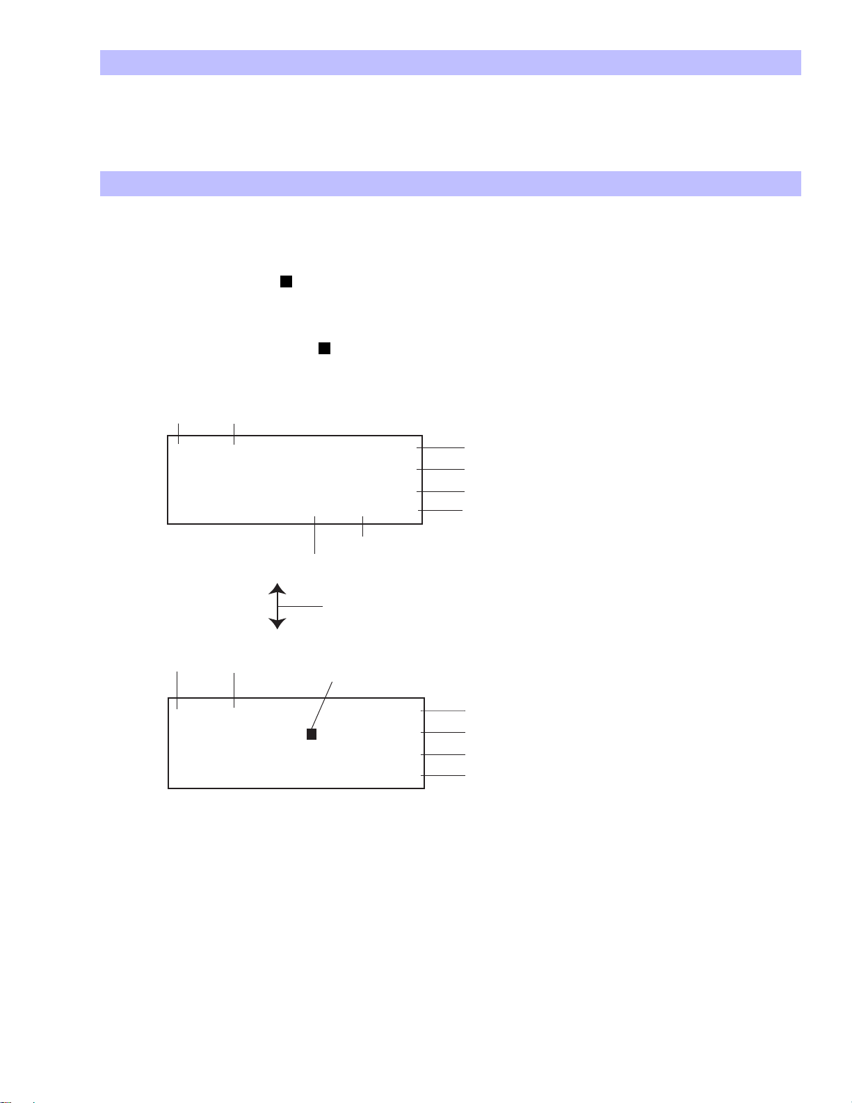
These bars indicate that the ECD is turned off.
-ECD- 01.54nA
APP.Poten +400mV
TimeConst. 1.0sec
T
emp/Set 25.6/25˚ C C
Cabinet setting
Actual temperature in the cabinet
Display can be switched between these two screens using the display key.
Indicates the pump is running.
Indicates the selected setting. Moves and makes changes using the edit key.
*PUMP* Press 0.64MPa
Flo
wRate 200μL/min
PulseF
reeMode ON
Press.Limit 14MP
Fig. 9 Display
a
Current status
Setting applied voltage (use the 10 keys for setting).
Most sensitive at 1.0 sec.
Noise is reduced at 3.0 sec. Select using the select key.
Indicates the thermocontroller is ON.
Pressure status
Setting flow rate. (Use the 10 keys for setting)
ON/OFF using the select key
Use the 10 keys for setting
9
 Loading...