

Page 1

USER MANUAL
TELEFON +49 7461 96580 0
www.eickemeyer.com
Art. No. 303720
MAGIC 6000
ULTRASOUND UNIT
Page 2

Page 3

Contents i
Contents
Intellectual Property Statement ......................................................................................................... II
Responsibility on the Manufacturer Party ......................................................................................... II
Warranty ........................................................................................................................................... III
Exemptions .................................................................................................................................. III
Customer Service Department .................................................................................................... III
Important Information ....................................................................................................................... IV
About This Manual ............................................................................................................................ V
Notation Conventions ........................................................................................................................ V
Operator!s Manuals ........................................................................................................................... V
Software Interfaces in this Manual ................................................................................................... VI
Conventions ..................................................................................................................................... VI
1 Safety Precautions ..................................................................................................... 1-1
1.1 Safety Classification ............................................................................................................. 1-1
1.2 Meaning of Signal Words ..................................................................................................... 1-2
1.3 Meaning of Safety Symbols ................................................................................................. 1-2
1.4 Safety Precautions ............................................................................................................... 1-3
1.5 Latex Alert .......................................................................................................................... 1-10
1.6 Warning Labels .................................................................................................................. 1-11
2 System Overview ........................................................................................................ 2-1
2.1 Intended Use ........................................................................................................................ 2-1
2.2 Contraindication ................................................................................................................... 2-1
2.3 Product and Model Code ..................................................................................................... 2-1
2.4 Product Specifications .......................................................................................................... 2-1
2.4.1 Imaging Mode ............................................................................................................... 2-1
2.4.2 Power supply ................................................................................................................ 2-1
2.4.3 Environmental Conditions ............................................................................................. 2-2
2.4.4 Size and weights ........................................................................................................... 2-2
2.5 System Configuration ........................................................................................................... 2-2
2.5.1 Standard Configuration ................................................................................................. 2-2
2.5.2 Probes Available ........................................................................................................... 2-2
2.5.3 Options ......................................................................................................................... 2-4
2.5.4 Peripherals Supported .................................................................................................. 2-4
2.6 Introduction of Each Unit ...................................................................................................... 2-5
2.6.1 I/O Panel ....................................................................................................................... 2-7
2.6.2 Power Supply Panel ..................................................................................................... 2-7
2.6.3 Control Panel ................................................................................................................ 2-8
2.7 Symbols .............................................................................................................................. 2-11
3 System Preparation .................................................................................................... 3-1
3.1 Move/Posit the System ........................................................................................................ 3-1
3.2 Power Supply ....................................................................................................................... 3-1
3.2.1 Connecting External Power Supply .............................................................................. 3-1
3.2.2 Powered by Battery ...................................................................................................... 3-1
3.3 Powering ON/ OFF ............................................................................................................... 3-2
3.3.1 Powering ON ................................................................................................................ 3-2
3.3.2 Powering OFF ............................................................................................................... 3-3
3.4 Connecting / Disconnecting a Probe .................................................................................... 3-4
3.4.1 Connecting a Probe ...................................................................................................... 3-4
Page 4

ii Contents
3.4.2 Disconnecting a Probe ................................................................................................. 3-4
3.5 Connecting the Footswitch ................................................................................................... 3-5
3.6 Connecting/ Removing a USB Storage Device .................................................................... 3-5
3.7 Graph / Text Printer .............................................................................................................. 3-5
3.8 Digital Video Printer .............................................................................................................. 3-7
3.9 Analog Video Printer ............................................................................................................ 3-7
3.10 External DVD ........................................................................................................................ 3-8
3.11 Basic Screen and Operation ................................................................................................ 3-8
3.11.1 Basic Screen ................................................................................................................. 3-8
3.11.2 Basic Operations of Screens ...................................................................................... 3-11
4 Exam Preparation ....................................................................................................... 4-1
4.1 Start an Exam ....................................................................................................................... 4-1
4.2 Animal Information ............................................................................................................... 4-1
4.2.1 New Animal Information ................................................................................................ 4-1
4.2.2 Retrieve Animal Information ......................................................................................... 4-5
4.3 Select Exam Mode and Probe ............................................................................................. 4-7
4.3.1 Supported Exam Modes ............................................................................................... 4-7
4.3.2 Selecting Exam Mode and Probe ................................................................................. 4-7
4.3.3 Dual Probe Switching ................................................................................................... 4-8
4.3.4 Bi-plane Endocavity Probe (65EB10EA) ...................................................................... 4-9
4.4 Selecting Imaging Mode ....................................................................................................... 4-9
4.5 Activate& Continue an Exam ............................................................................................... 4-9
4.5.1 Activate an Exam .......................................................................................................... 4-9
4.5.2 Continue an Exam ........................................................................................................ 4-9
4.6 Pause & End an Exam ......................................................................................................... 4-9
4.6.1 Pause and Exam .......................................................................................................... 4-9
4.6.2 End an Exam .............................................................................................................. 4-10
5 Image Optimization ..................................................................................................... 5-1
5.1 Switching Between Image Modes ........................................................................................ 5-1
5.2 Basic Operations .................................................................................................................. 5-1
5.3 B Mode ................................................................................................................................. 5-2
5.3.1 B Mode Exam Protocol ................................................................................................. 5-2
5.3.2 B Mode Parameters ...................................................................................................... 5-2
5.3.3 B Mode Image Optimization ......................................................................................... 5-3
5.4 M Mode ................................................................................................................................ 5-8
5.4.1 M Mode Exam Protocol ................................................................................................ 5-8
5.4.2 M Mode Parameters ..................................................................................................... 5-9
5.4.3 M Mode Image Optimization ......................................................................................... 5-9
5.5 Image Preset ...................................................................................................................... 5-12
5.5.1 Image Preset .............................................................................................................. 5-12
6 Display & Cine Review ............................................................................................... 6-1
6.1 Image Display ....................................................................................................................... 6-1
6.1.1 Splitting Display ............................................................................................................ 6-1
6.1.2 Image Magnification ..................................................................................................... 6-1
6.1.3 Freeze/ Unfreeze the Image ......................................................................................... 6-2
6.2 Cine Review ......................................................................................................................... 6-3
6.2.1 Entering/ Exiting Cine Review ...................................................................................... 6-3
6.2.2 Cine Review in 2D Mode .............................................................................................. 6-4
6.2.3 Cine Review in M Mode ................................................................................................ 6-4
6.2.4 Linked Cine Review ...................................................................................................... 6-5
Page 5

Contents iii
6.3 Cine Memory ........................................................................................................................ 6-5
6.3.1 Cine Memory Setting .................................................................................................... 6-5
6.3.2 Cine Memory Clear ....................................................................................................... 6-5
6.4 Preset ................................................................................................................................... 6-6
7 Measurement ............................................................................................................... 7-1
7.1 Basic operations ................................................................................................................... 7-1
7.2 General Measurements ........................................................................................................ 7-1
7.2.1 2D General Measurements .......................................................................................... 7-1
7.2.2 M General Measurements ............................................................................................ 7-2
7.3 Application Measurement ..................................................................................................... 7-2
7.4 Measurement Accuracy ........................................................................................................ 7-3
8 Comments and Body Marks ...................................................................................... 8-1
8.1 Comments ............................................................................................................................ 8-1
8.1.1 Comment Basic Procedures ......................................................................................... 8-1
8.1.2 Comment Menu ............................................................................................................ 8-1
8.1.3 Adding Comments ........................................................................................................ 8-2
8.1.4 Moving Comments ........................................................................................................ 8-3
8.1.5 Editing Comments ........................................................................................................ 8-3
8.1.6 Deleting Comments ...................................................................................................... 8-3
8.2 Body Mark ............................................................................................................................ 8-4
8.2.1 Body Mark Operation Procedures ................................................................................ 8-4
8.2.2 Menu ............................................................................................................................. 8-4
8.2.3 Adding Body Marks....................................................................................................... 8-4
8.2.4 Moving Body Marks ...................................................................................................... 8-4
8.2.5 Deleting Body Marks..................................................................................................... 8-5
9 Data Management ....................................................................................................... 9-1
9.1 Animal Information Management ......................................................................................... 9-1
9.1.1 Enter Animal Information .............................................................................................. 9-1
9.1.2 Animal Information Setting ........................................................................................... 9-1
9.2 Image File Management ...................................................................................................... 9-2
9.2.1 Storage Media ............................................................................................................... 9-2
9.2.2 Image File Formats ....................................................................................................... 9-2
9.2.3 Image Storage Preset ................................................................................................... 9-2
9.2.4 Saving Images to the System ....................................................................................... 9-3
9.2.5 Quickly Saving Images to USB Flash Drive ................................................................. 9-3
9.2.6 Quickly Saving Full Screen Image to the System ........................................................ 9-4
9.2.7 Thumbnails ................................................................................................................... 9-4
9.2.8 Image Review and Analysis .......................................................................................... 9-4
9.2.9 iVision ........................................................................................................................... 9-6
9.2.10 Sending Image File ....................................................................................................... 9-8
9.3 Report Management............................................................................................................. 9-8
9.4 Data Management (iStation)............................................................................................... 9-10
9.4.1 Searchingan Animal .................................................................................................... 9-11
9.4.2 Animal Data View & Management .............................................................................. 9-11
9.5 Backing Up and Erasing Files through DVD Drive ............................................................. 9-13
9.6 Task Manager ..................................................................................................................... 9-13
9.7 Access Control ................................................................................................................... 9-15
9.7.1 Access Setting ............................................................................................................ 9-15
9.7.2 Setting Access Control ............................................................................................... 9-15
9.7.3 System Login .............................................................................................................. 9-15
Page 6

iv Contents
9.7.4 Add/ Delete a User ..................................................................................................... 9-16
9.7.5 Modify Password ........................................................................................................ 9-18
10 DICOM ........................................................................................................................ 10-1
10.1 DICOM Preset .................................................................................................................... 10-1
10.1.1 Network Preset ........................................................................................................... 10-1
10.1.2 DICOM Preset ............................................................................................................ 10-2
10.1.3 DICOM Service ........................................................................................................... 10-4
10.2 Verify Connectivity ............................................................................................................ 10-11
10.3 DICOM Service ................................................................................................................ 10-11
10.3.1 DICOM Storage ........................................................................................................ 10-12
10.3.2 DICOM Print ............................................................................................................. 10-12
10.3.3 DICOM Worklist ........................................................................................................ 10-13
10.3.4 Storage Commitment ................................................................................................ 10-15
10.4 DICOM Media Storage ..................................................................................................... 10-15
10.5 Showcase Recording ....................................................................................................... 10-16
10.6 DICOM Task Manager ...................................................................................................... 10-16
11 Setup ...........................................................................................................................11-1
11.1 System Preset .................................................................................................................... 11-2
11.1.1 Region ........................................................................................................................ 11-2
11.1.2 General ....................................................................................................................... 11-3
11.1.3 Image Preset .............................................................................................................. 11-4
11.1.4 Meas ........................................................................................................................... 11-5
11.1.5 Key Config .................................................................................................................. 11-5
11.1.6 Biopsy ......................................................................................................................... 11-7
11.1.7 Admin .......................................................................................................................... 11-7
11.2 Exam Preset ....................................................................................................................... 11-7
11.2.1 Exam Selection ........................................................................................................... 11-8
11.2.2 Exam Configuration .................................................................................................... 11-8
11.3 Image Preset ...................................................................................................................... 11-9
11.4 Measure Preset ................................................................................................................ 11-10
11.5 Body Mark Preset ............................................................................................................. 11-10
11.5.1 Preset Body Mark for Exam Mode ............................................................................ 11-10
11.5.2 Custom Body Marks .................................................................................................. 11-11
11.6 Comment Preset .............................................................................................................. 11-12
11.6.1 Custom Comments ................................................................................................... 11-12
11.7 Print Preset ....................................................................................................................... 11-13
11.8 Network Preset ................................................................................................................. 11-14
11.9 Workstation Setting .......................................................................................................... 11-14
11.10 Manage Settings .............................................................................................................. 11-14
11.10.1 Exporting Setup Data ................................................................................................ 11-14
11.10.2 Importing Setup Data ................................................................................................ 11-14
11.11 Maintenance ..................................................................................................................... 11-15
11.12 System Information .......................................................................................................... 11-15
12 Probes and Biopsy ................................................................................................... 12-1
12.1 Probe .................................................................................................................................. 12-1
12.1.1 Name and Function of Each Part of the Transducer .................................................. 12-2
12.1.2 Orientation of the Ultrasound Image and the Transducer Head ................................. 12-4
12.1.3 Operating Procedures ................................................................................................ 12-4
12.1.4 Wearing the Transducer Sheath ................................................................................. 12-7
12.1.5 Probes Cleaning and Disinfection .............................................................................. 12-8
Page 7

Contents v
12.1.6 Storage and Transportation ...................................................................................... 12-10
12.2 Biopsy Guide .................................................................................................................... 12-10
12.2.1 Basic Procedures for Biopsy Guiding ....................................................................... 12-12
12.2.2 Needle-guided Brackets ........................................................................................... 12-13
12.2.3 Biopsy Preset ............................................................................................................ 12-18
12.2.4 Needle-guided Bracket Inspection and Installation .................................................. 12-19
12.2.5 Biopsy Menu ............................................................................................................. 12-23
12.2.6 Verify Biopsy Guide Line........................................................................................... 12-23
12.2.7 Removing the Needle-guided Bracket ...................................................................... 12-24
12.2.8 Clean and Sterilize the Needle-guided Bracket ........................................................ 12-27
12.2.9 Storage and Transportation ...................................................................................... 12-28
12.2.10 Disposal .................................................................................................................... 12-28
13 Battery ....................................................................................................................... 13-1
13.1 Overview ............................................................................................................................ 13-1
13.2 Precautions ........................................................................................................................ 13-2
13.3 Installing and Removing the Batteries ................................................................................ 13-2
13.4 Battery Status Indicator ...................................................................................................... 13-3
13.5 One Full Discharge / Charge Cycle .................................................................................... 13-3
13.6 Checking Battery Performance .......................................................................................... 13-4
13.7 Battery Disposal ................................................................................................................. 13-4
14 Acoustic Output ........................................................................................................ 14-1
14.1 Concerns with Bioeffects .................................................................................................... 14-1
14.2 Prudent Use Statement ...................................................................................................... 14-1
14.3 ALARA Principle (As Low As Reasonably Achievable) ...................................................... 14-1
14.4 MI/TI Explanation ............................................................................................................... 14-2
14.4.1 Basic Knowledge of MI and TI .................................................................................... 14-2
14.4.2 MI/TI Display ............................................................................................................... 14-2
14.5 Acoustic Power Setting ...................................................................................................... 14-3
14.6 Acoustic Power Control ...................................................................................................... 14-3
14.7 Acoustic Output .................................................................................................................. 14-4
14.7.1 Derated Ultrasonic Output Parameters ...................................................................... 14-4
14.7.2 Limits of Acoustic Output ............................................................................................ 14-5
14.7.3 Differences between Actual and Displayed MI and TI ................................................ 14-5
14.8 Measurement Uncertainty .................................................................................................. 14-5
14.9 References for Acoustic Power and Safety ........................................................................ 14-6
15 Guidance and Manufacturer’s Declaration ............................................................. 15-1
16 System Maintenance ................................................................................................ 16-1
16.1 Daily Maintenance .............................................................................................................. 16-1
16.1.1 Cleaning the System .................................................................................................. 16-1
16.1.2 Checking Transducer .................................................................................................. 16-3
16.1.3 Backup of the System Hard Drive .............................................................................. 16-3
16.2 Maintenance Checks by Service Engineer ........................................................................ 16-3
16.3 Consumables and Periodic Part Replacement .................................................................. 16-3
16.4 Troubleshooting .................................................................................................................. 16-3
Appendix A Transducer Maximum Surface Temperature ....................................... A-1
Appendix B Acoustic Output Reporting Table (60601-2-37) ................................... B-1
Page 8

Page 9

I
d. All rights Reserved.
IMPORTANT!
The system is veterinary use only.
The label of veterinary information is adhered to the system. Please observe the instruction.
The following label applies to U.S.A. only.
Page 10

II
Responsibility on the Manufacturer Party
Contents of this manual are subject to change without prior notice.
All information contained in this manual is believed to be correct. :Hshall not be liable
for errors contained herein or for incidental or consequential damages in connection with the
furnishing, performance, or use of this manual.
:HDUH responsible for the effects on safety, reliability and performance of this product,
only if:
z all installation operations, expansions, changes, modifications and repairs of this
product are conducted by authorized personnel;
z the electrical installation of the relevant room complies with the applicable national
and local requirements; and
z the product is used in accordance with the instructions for use.
z VNC ver. 1.0 is free open source software, the performance of VNC
ver. 1.0 is not guaranteed
Note
This equipment must be operated by skilled/trained clinical professionals.
Warning
It is important for the hospital or organization that employs this equipment to carry out a
reasonable service/maintenance plan. Neglect of this may result in machine breakdown or
personal injury.
Page 11

III
Warranty
THIS WARRANTY IS EXCLUSIVE AND IS IN LIEU OF ALL OTHER WARRANTIES,
EXPRESSED OR IMPLIED, INCLUDING WARRANTIES OF MERCHANTABILITY OR
FITNESS FOR ANY PARTICULAR PURPOSE.
Exemptions
2bligation or liability under this warranty does not include any transportation or
other charges or liability for direct, indirect or consequential damages or delay resulting from
the improper use or application of the product or the use of parts or accessories not approved
or repairs by people other than authorized personnel.
This warranty shall not extend to:
Malfunction or damage caused by improper use or man-made failure.
Malfunction or damage caused by unstable or out-of-range power input.
Malfunction or damage caused by force majeure such as fire and earthquake.
Malfunction or damage caused by improper operation or repair by unqualified or
unauthorized service people.
Malfunction of the instrument or part whose serial number is not legible enough.
Others not caused by instrument or part itself.
Page 12

IV
Important Information
1. It is the customer•s responsibility to maintain and manage the system after delivery.
2. The warranty does not cover the following items, even during the warranty period:
(1) Damage or loss due to misuse or abuse.
(2) Damage or loss caused by Acts of God such as fires, earthquakes, floods, lightning,
etc.
(3) Damage or loss caused by failure to meet the specified conditions for this system,
such as inadequate power supply, improper installation or environmental conditions.
(4) Damage or loss due to use of the system outside the region where the system was
originally sold.
(5) Damage or loss involving the system purchased from aQRWKHU source or
its authorized agents.
3. This system shall not be used by persons other than fully qualified and certified medical
personnel.
4. Do not make changes or modifications to the software or hardware of this system.
5. In no event shall (LFNHPH\HUbe liable for problems, damage, or loss caused by relocation,
modification, or repair performed by personnel other than those designated.
6. The purpose of this system is to provide physicians with data for clinical diagnosis. It is
the physician•s responsibility for diagnostic procedures. (LFNHPH\HU shall not be liable for the
results of diagnostic procedures.
7. Important data must be backed up on external memory media.
8. (LFNHPH\HU shall not be liable for loss of data stored in the memory of this system caused by
operator error or accidents.
9. This manual contains warnings regarding foreseeable potential dangers, but you shall
always be alert to dangers other than those indicated as well. (LFNHPH\HU shall not be liable
for damage or loss that results from negligence or from ignoring the precautions and
operating instructions described in this operator•s manual.
10. If the manager for this system is changed, be sure to hand over this operator•s manual to
the new manager.
Page 13

V
About This Manual
This operator!s manual describes the operating procedures for this diagnostic ultrasound
system DP-50Vet and the compatible probes. To ensure safe and correct operations, carefully
read and understand the manual before operating the system.
Notation Conventions
In this operator!s manual, the following words are used besides the safety precautions (refer
to "Safety Precautions"). Please read this operator!s manual before using the system.
CAUTION:
1. The diagnostic ultrasound system is not intended for
ophthalmic use. Its use in this clinical specialty is
contraindicated.
2. United States federal law restricts this device to be sale by or
on the order of a physician.
Operator’s Manuals
Please read the operator!s manuals carefully before operating the system.
The operator!s manuals consist of manuals for the main unit and transducers. The English
manuals are provided on paper; however, the manuals, which are translated into languages
other than English, are provided in CD (Compact Disc).
The content of the operator manual, such as screens, menus or descriptions, may be different
from what you see in your system. The content varies depending upon the software version,
options and configuration of the system.
z Operator!s Manual [Basic Volume]: Describes the basic functions and operations of
the system, safety precautions, exam modes, imaging modes, preset, maintenance
and acoustic output, etc.
z Operator!s Manual [Advanced Volume]: Describes measurement preset,
measurements and calculations, etc.
z Operation Note: Contains quick guide for basic operations of the system.
NOTE: The accompanying manuals may vary depending upon the specific system you
purchased. Please refer to the packing list.
Page 14

VI
Software Interfaces in this Manual
Depending on the software version, preset settings and optional configuration, the actual
interfaces may be different from those in this manual.
Conventions
In this manual, these conventions are used to describe the buttons on the control panel, the
items in menu, buttons in dialog box and some basic operations:
z <Buttons>: The angular bracket indicates buttons, knobs and other controls on
control panel.
z [Items in menu and buttons in dialog box]: The square bracket indicates items in
menu or buttons in dialog box.
z Click [Items or Button]: Move the cursor to the item or button and press <Set>, or
click it on the menu.
z [Items in Menu]Æ[Items in Submenu]: Selects a submenu item following the path.
z [Dyn Rng (Value)]: Indicates menu items with parameter, (value) shows the current
value of the item.
Page 15

Safety Precautions 1-1
1 Safety Precautions
1.1 Safety Classification
According to the type of protection against electric shock:
CLASS I EQUIPMENT
According to the degree of protection against electric shock:
Type-BF applied part
According to the degree of protection against harmful ingress of water:
Main unit: IPX0
Probes: IPX7
According to the degree of safety of application in the presence of a FLAMMABLE
ANESTHETIC MIXTURE WITH AIR or WITH OXYGEN OR NITROUS OXIDE:
EQUIPMENT not suitable for use in the presence of a FLAMMABLE ANESTHETIC
MIXTURE WITH AIR or WITH OXYGEN OR NITROUS OXIDE
According to the mode of operation:
CONTINUOUS OPERATION
According to the installation and use:
PORTABLE EQUIPMENT
MOBILE EQUIPMENT
Page 16
1-2 Safety Precautions
1.2 Meaning of Signal Words
In this manual, the signal words"
DANGER!, # WARNING!, # CAUTION!,
#NOTE! and "Tips" are used regarding safety and other important instructions. The signal
words and their meanings are defined as follows. Please understand their meanings clearly
before reading this manual.
Signal word Meaning
DANGER
Indicates an imminently hazardous situation that, if not avoided, will result
in death or serious injury.
WARNING
Indicates a potentially hazardous situation that, if not avoided, could result
in death or serious injury.
CAUTION
Indicates a potentially hazardous situation that, if not avoided, may result
in minor or moderate injury.
NOTE
Indicates a potentially hazardous situation that, if not avoided, may result in
property damage.
Tips Important information that helps you to operate the system more effectively.
1.3 Meaning of Safety Symbols
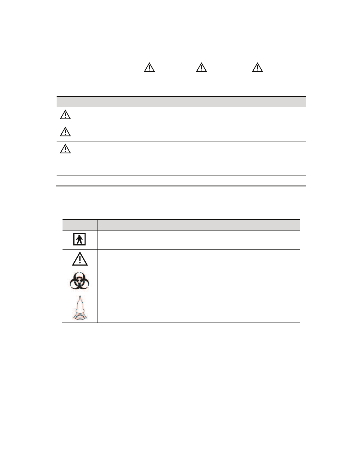
Symbol Description
Type-BF applied part.
The ultrasound probes connected to this system are type-BF applied parts.
General warning, caution, risk of danger.
Patient/user infection due to contaminated equipment. Be careful when
performing the cleaning, disinfection and sterilization.
Patient injury or tissue damage from ultrasound radiation. It is required to
practice ALARA when operating ultrasound system.
Page 17

Safety Precautions 1-3
1.4 Safety Precautions
Please observe the following precautions to ensure animal and operator•s safety when using
this system.
DANGER:
DO NOT use flammable gasses, such as anesthetic gas or
hydrogen, or flammable liquids such as ethanol, near this
system, because there is danger of explosion.
WARNING:
1.
Do connect the power plug of this system and power plugs
of the peripherals to wall receptacles that meet the ratings
indicated on the rating nameplate. Using a multifunctional
receptacle may affect the system protective grounding
performance, and cause the leakage current to exceed
safety requirements.
Use the cable provided with this system to connect the
printer. Other cables may result in electric shock.
You must use the power adapter provided with the system;
otherwise electric shock may result.
You can only adopt the power supply method providedE\XV
other power supply modes (e.g. using a UPS) may
result in electric shock.
2.
Connect the protective grounding conductor before
turning ON the system. Disconnect the grounding cable
after turning OFF the system. Otherwise, electric shock
may result.
3.
For the connection of power and grounding, follow the
appropriate procedures described in this operator’s
manual. Otherwise, there is risk of electric shock. DO
NOT connect the grounding cable to a gas pipe or water
pipe; otherwise, improper grounding may result or a gas
explosion may occur.
4.
Before cleaning the system, disconnect the power cord
from the outlet. System failure and electric shock may
result.
5.
This system is not water-proof designed. Do Not use this
system in any place where water or any liquid leakage
may occur. If any water is sprayed on or into the system,
electric shock
or device malfunction may result. If water is
accidentally sprayed on or into the system, contact
Customer Service Department or sales
representative.
6.
Do not use a transducer that has a damaged, scratched
surface, or exposed wiring of any kind. Immediately stop
using the transducer and contact Customer
Service Department or sales representative. There is risk
of electric shock if using a damaged or scratched
transducer.
Page 18

1-4 Safety Precautions
7.
DO NOT allow the animal to contact the live parts of the
ultrasound system or other devices, e.g. signal I / O
ports. Electric shock may occur.
8.
Do not use an aftermarket probe other than those
specified by XV. The probes may damage the
system causing a profound failure, e.g. a fire in the worst
case.
9.
Do not subject the transducers to knocks or drops. Use
of a defective transducer may cause an electric shock.
10.
Do not open the covers and front panel of the system.
Short circuit or electric shock may result when the
system hardware is exposed and powered on.
11.
Do not use this system when any digital device such as a
high-frequency electrotome, high-frequency therapeutic
device or defibrillator is applied already. Otherwise, there
is a risk of electric shock to the animal.
12.
When moving the system, you should first fold the
keyboard, disconnect the system from other devices
(including probes) and disconnect the system from the
power supply.
13.
Accessory equipment connected to the analog and digital
interfaces must comply with the relevant IEC standards
(e.g., IEC 60950 information technology equipment safety
standard and IEC 60601-1 medical equipment
standard).Furthermore, all configurations must comply
with the standard IEC 60601-1-1.It is the responsibility of
the person, who connects additional equipment to the
signal input or output ports and configures a medical
system, to verify that the system complies with the
requirements of IEC 60601-1-1.If you have any questions
regarding these requirements, consult your sales
representative.
14.
Prolonged and repeated use of keyboards may result in
hand or arm nerve disorders for some individuals.
Observe the local safety or health regulations concerning
the use of keyboards.
15.
When using intra-cavity transducers, do not activate the
transducer outside the animal’s body.
CAUTION:
1. Precautions concerning clinical examination techniques:
z This system must be used only by qualified medical
professionals.
z This operator!s manual does not describe clinical
examination techniques. The clinician should select the
proper examination techniques based on specialized
training and clinical experience.
Page 19

Safety Precautions 1-5
2. Malfunctions due to radio wave:
z If a radio wave emitting device is used in the proximity of
this system, it may interfere with operations. Do not bring
or use devices that generate radio waves, such as
cellular telephones, transceivers, and radio controlled
toys, in the room where the system is installed.
z If a person brings a device that generates radio waves
near the system, ask him / her to immediately turn OFF
the device.
3. Precautions concerning movement of the system:
z When you place the system on the mobile trolley and
move them together, you must secure all objects on the
mobile trolley to prevent them from falling. Otherwise you
should separate the system from the mobile trolley and
move them individually.
When you have to move the system with the mobile
trolley upward or downward the stairs, you must separate
them first and then move them individually.
z Object placed on the monitor may fall and injure an
individual when moving.
z Fasten and fully secure any peripheral device before
moving the system. A loose peripheral device may fall
and injure an individual.
4.
DO NOT expose the system to excessive vibration
through transportation. Mechanical damage may result.
5.
Do not connect this system to outlets with the same
circuit breakers and fuses that control the current of
devices such as life-support systems. If this system
malfunctions and generates overcurrent, or when there is
an instantaneous current at power ON, the circuit breakers
and fuses of the buildingಬ
s supply circuit may be tripped.
6.
Always keep the system dry. Avoid transporting this
system quickly from a cold place to a warm place;
otherwise condensation or water droplets may form
allowing a short circuit and possible electric shock.
7.
If the circuit protector is tripped, it indicates that the
system or a peripheral device was improperly shut down
and the system is unstable. You cannot repair the system
under this circumstance and must call the
Customer Service Department or sales representative.
8.
There is no risk of high-temperature burns during normal
ultrasound examinations. It is possible for the surface
temperature of the transducer to exceed the body
temperature of an animal due to environmental
temperature and exam type combinations. Do not apply
the transducer to the same region on the animal for a long
time. Apply the transducer only for a period of time
required for the purpose of diagnosis.
Page 20

1-6 Safety Precautions
9.
The system and its accessories are not disinfected or
sterilized prior to delivery. The operator is responsible for
the cleaning and disinfection of transducers and
sterilization of biopsy brackets according to the manuals,
prior to the use. All items must be thoroughly processed
to completely remove harmful residual chemicals, which
will not only be harmful to the human body, but also
damage the accessory.
10.
It is necessary to press [End Exam] to end the current
scan that is in progress and clear the current Animal
Information field. Otherwise, new animal data may be
combined with the previous animal data.
11.
DO NOT connect or disconnect the systemಬ
s power cord
or its accessories (e.g., a printer) without turning OFF the
power first. This may damage the system and its
accessories or cause electric shock.
12.
If the system is powered off improperly during operation,
it may result in data damage of the systemಬ
s hard disk or
system failure.
13.
Do not use the system to examine a fetus for a long period
of time.
14.
Do not use a USB memory device (e.g., a USB flash drive,
removable hard disk) which has unsafe data. Otherwise,
system damage may result.
15.
It is recommended to only use the video devices specified
in this manual.
16.
Do not use gel, disinfectant, probes, probe sheath or
needle-guided brackets that are not compatible with the
system.
17.
Read the Acoustic Output Principle in the operation
manual carefully before operate this system on clinical
examination.
18.
Please use the ultrasound gel compliant with the relevant
local regulations.
Page 21

Safety Precautions 1-7
NOTE: 1. DO NOT use the system in the vicinity of strong electromagnetic field (such
as a transformer), which may affect the performance of the system.
2. DO NOT use the system in the vicinity of high-frequency radiation source,
which may affect the performance of the system or even lead to failure.
3. When using or placing the system, keep the system horizontal to avoid
disbalance.
4. To avoid damaging the system, DO NOT use it in following environment:
(1) Locations exposed to direct sunlight;
(2) Locations subject to sudden changes in environmental temperature;
(3) Dusty locations;
(4) Locations subject to vibration;
(5) Locations near heat generators;
(6) Locations with high humidity.
5. Turn ON the system only after the power has been turned OFF for a while. If
the system is turned ON immediately after being turned OFF, the system may
not be rebooted properly and could malfunction.
6. Remove ultrasound gel from the face of a probe when the examination is
complete. Water in the gel may enter the acoustic lens and adversely affect
the performance and safety of the transducer.
7. You should properly back up the system to a secure external storage media,
including system configuration, settings and animal data. Data stored to the
systemಬs hard drive may be lost due to system failure, improper operation or
accident.
8. Do not apply external force to the control panel, otherwise, the system may
be damaged.
9. If the system is used in a small room, the room temperature may rise. Please
provide proper ventilation and free air exchange.
10. To dispose of the system or any part, contactCustomer Service
Department or sales representative. (LFNHPH\HU is not responsible for
anysystem content or accessories that have been discarded improperly.
(LFNHPH\HU is not responsible for any system content or accessories that
Kave beendiscarded improperly.
11. Electrical and mechanical performance may be degraded due to long usage
(such as current leakage or distortion and abrasion), the image sensitivity and
precision may become worse too. To ensure optimal system operations, it is
recommended that you maintain the system under a service
agreement.
12. Ensure that the current exam date and time are the same as the system date
and time.
13. DO NOT turn OFF the power supply of the system during printing, file storage
or invoking other system operations. An interrupted process may not be
completed, and can become lost or corrupted.
14. The system should be powered by battery when the integrality and reliability
of the protective grounding of external power supply is indeterminate.
15. The replaceable fuse is inside the chassis. Refer replacing job to
service engineers or engineers authorized only.
Page 22

1-8 Safety Precautions
Please read the following precautions carefully to ensure the safety of the animal and the
operator when using the probes.
WARNING:
1.
The ultrasonic probe is only for use with the specified
ultrasonic diagnostic system. Please refer to the “2.5.2
Probes Available” to select the proper probe.
2.
The ultrasonic probe must be used only by qualified
professionals.
3.
Confirm that the probe and cable are normal before and
after each examination. Electrical shock may result from
a defective probe.
4.
Do not subject the probe to shock. A defective probe may
cause electric shock to the animal.
5.
Do not disassemble the probe to avoid the possibility of
electric shock.
6.
Never immerse the probe connector into liquids such as
water or disinfectant because the connector is not
waterproof. Immersion may cause electric shock or
malfunction.
7.
A probe sheath must be installed over the probe before
performing intra-cavity or biopsy examination.
CAUTION:
1.
When using the probe, wear sterile gloves to prevent
infection.
2.
Be sure to use ultrasound sterile gel. Please use the
ultrasound gel compliant with the relevant local
regulations. And manage the ultrasound gel properly to
ensure that it does not become a source of infection.
3.
In normal diagnostic ultrasound mode, there is no danger
of a normal-temperature burn; however, keeping the probe
on the same region of the animal for a long time may
cause such a burn.
4.
Do not use the carrying case for storing the transducer. If
the carrying case is used for storage, it may become a
source of infection.
5.
It is required to practice ALARA when operating
ultrasound system. Minimize the acoustic power without
compromising the quality of images.
6.
The probe and accessories supplied with it are not
delivered disinfected or sterilized. Sterilization (or highlevel disinfect) before use is required.
Page 23

Safety Precautions 1-9
7.
Disposable components are packaged sterile and are
single-use only. Do not use if integrity of packaging
violated or if expiration date has passed. Please use the
disposable components compliant with the relevant local
regulations.
8.
Please use the disinfection or sterilization solution that
recommended in this operator’s manual, otherwise
ZH will not be liable for damage caused by other
solutions. If you have any questions, please contact
Customer Service Department or sales
representative.
9.
The probe sheath contains natural rubber that can cause
allergic reactions in some individuals.
10.
Do not use pre-lubricated condoms as a sheath. Lubricant
may not be compatible with the transducer material and
damage may result.
11.
Transducer damage may be caused by inappropriate gel,
detergent or cleanser:
Do not soak or saturate transducers with solutions
containing alcohol, bleach, ammonium chloride
compounds, acetone or formaldehyde.
Avoid contact with solutions or coupling gels containing
mineral oil or lanolin.
NOTE: 1. Read the following precautions to prevent the probe from malfunction:
z Clean and disinfect the transducer before and after each examination.
z After the examination, wipe off the ultrasound gel thoroughly.
Otherwise, the ultrasound gel may solidify and the image quality
would be degraded.
2. Ambient conditions:
To prevent the transducer from being damaged, do not use it where it will be
exposed to:
z Direct sunlight or X-rays
z Sudden changes in temperature
z Dust
z Excessive vibration
z Heat generators
Use the probes under the following ambient conditions:
z Ambient temperature: 0°C ~ 40°C
z Relative humidity: 30% to 85% (no condensation)
z Atmospheric pressure: 700 hPa ~ 1060 hPa
3. Repeated disinfection will eventually damage the probe, please check the
probe's performance periodically.
Page 24

1-10 Safety Precautions
NOTE: 1. The following definition of the WEEE label applies to EU member
states only: The use of this symbol indicates that this system
should not be treated as household waste. By ensuring that this
system is disposed of correctly, you will help prevent bringing
potential negative consequences to the environment and human
health. For more detailed information with regard to returning and
recycling this system, please consult the distributor from whom
you purchased the system.
2. For system products, this label may be attached to the main unit only.
1.5 Latex Alert
When choosing a probe sheath, it is recommended that you directly contact CIVCO for
obtaining probe sheath, pricing information, samples and local distribution information. For
CIVCO information, please contact the following:
CIVCO Medical Instruments
Tel: 1-800-445-6741
WWW.civco.com
WARNING:
Allergic reactions in latex (natural rubber) sensitive animals may
range from mild skin reactions (irritation) to fatal anaphylactic
shock, and may include difficulty in breathing (wheezing),
dizziness, shock, swelling of the face, hives, sneezing or itching
of the eyes (FDA Medical Alert on latex products, “Allergic
Reactions to Latex-containing Medical Devices”, issued on March
29, 1991).
Page 25

Safety Precautions 1-11
1.6 Warning Labels
The warning labels are attached to this system in order to call your attention to potential
hazards. The symbol
on the warning labels indicates safety precautions.
The warning labels use the same signal words as those used in the operator!s manual. Read
operator!s manual carefully before using the system.
The name, pattern and meaning of each warning label are described as follows:
No. Warning Labels Meaning
1
Before using the system, be sure to carefully
read the relevant content of this operator!s
manual.
2
(a) (b)
(a) General warning, caution, risk of danger.
(b) DANGER: There is explosion risk if the
system is used with flammable anesthetics.
3
Cautions that the system must not be removed
covers because the high voltage may cause
electric shock.
4 The following labels are
available when the system
works with the mobile trolley.
(a) (b)
(a) DO NOT sit on the system.
(b) DO NOT push the trolley when the casters
are locked.
5 The following label is
available when the system
works with the mobile trolley
UMT-150.
Open the keyboard before moving the trolley.
Page 26

Page 27

System Overview 2-1
2 System Overview
2.1 Intended Use
The Digital Ultrasonic Diagnostic Imaging System is intended for use in abdomen, thoracic,
cardiac, tendinous, small parts, ophthalmic, reproduction system exams for animals such as
dog, cat, equine, bovine and ovine, etc.
2.2 Contraindication
None.
2.3 Product and Model Code
NOTE: The functions described in the operator!s manual may vary depending upon the
specific system you purchased.
2.4 Product Specifications
2.4.1 Imaging Mode
B Mode
M Mode
2.4.2 Power supply
Voltage
100-240V
Frequency 50/60Hz
Input Power 1.5-0.8A
Fuse
250V~ T3.15AH
DP
-
Model code
Product code
Page 28

2-2 System Overview
2.4.3 Environmental Conditions
Operational Conditions Storage and Transportation Conditions
Ambient
temperature
0ć40ć -20ć55ć
Relative
humidity
30%85% (no condensation) 30%95% (no condensation)
Atmospheric
pressure
700hPa1060hPa 700hPa1060hPa
2.4.4 Size and weights
z Size: 190mm×415mm×378mm (Depth×Weight×Height)
z Net Weight: 8.6 kg (including battery and ACDC module)
2.5 System Configuration
2.5.1 Standard Configuration
Main unit
Accessories
z Operator!s manual
z Ultrasound gel
z Power cable
z Multilingual controls overlay
z Probe holder
z Dust-proof cover
2.5.2 Probes Available
No. Probe Model Category Intended Use
Region
Applied
1. 35C50EA Convex Big animal!s abdomen Body surface
2. 65C15EA Convex
Small animal!s abdomen, thoracic, and
cardiac
Body surface
3. 65EB10EA Convex Big animal!s reproductive system Transrectal
4. 75L38EA
Linear
array
Big animal!s tendon, small animal!s
abdomen, small parts and eyeball
Body surface
5. 75L53EA
Linear
array
Big animal!s tendon, small animal!s
abdomen, small parts and eyeball
Body surface
WARNING:
Do not use this system in the conditions other than those
specified.
Page 29

System Overview 2-3
No. Probe Model Category Intended Use
Region
Applied
6. 10L24EA
Linear
array
Small animal!s abdomen, small parts and
eyeball
Body surface
7. 50L60EAV
Linear
array
Big animal!s reproductive system and
tendon
Transrectal,
body surface
8. 75L50EAV
Linear
array
Big animal!s reproductive system and
tendon
Transrectal,
body surface
Some of the probes have matched needle-guided brackets for biopsy, the available probes
and the corresponding needle-guided brackets are listed as follows:
Probe Model
Needle-guided
Bracket Model
Biopsy Angle/
Depth (±1°)
Applicable Biopsy Needle
35C50EA
NGB-001
Metal/needle
detachable;
metal/needle undetachable
25°, 35°, 45° 13G, 15G, 16G, 18G, 20G
75L38EA
NGB-002
metal/needle undetachable
40e, 50e, 60e
13G, 15G, 16G, 18G, 20G
65EB10EA
NGB-004
metal/needle undetachable
/
16G, 17G, 18G
65C15EA
NGB-005
metal/needle undetachable
12.7°, 24.2° 13G, 15G, 16G, 18G, 20G
75L53EA
NGB-007
Plastic/needle
detachable;
Metal/needle
detachable
40°, 50°, 60°
Metal: 14G, 16G, 18G, 20G, 22G
Plastic: 13G, 15G, 16G, 18G, 20G
10L24EA
NGB-016
Metal/needle
detachable
30°, 40°, 50° 14G, 16G, 18G, 20G, 22G
Page 30

2-4 System Overview
2.5.3 Options
No. Item
1 iClear module
2 IMT module
3
DICOM basic module (including: task management, DICOM storage, DICOM print,
DICOM storage commitment, DICOM media storage (including DICOM DIR) and
etc.)
4
DICOM worklist module (only can be applied with the DICOM basic function module
configured)
5
DVD R/W Drive:
Model: SE-S224(USB port)
6 Footswitch
7 Battery Pack (LI34I002A)
8 Mobile Trolley (UMT-50 or UMT-150)
9 Needle-guided bracket
10 Pack
2.5.4 Peripherals Supported
No. Item Model
1. Graph / text printer
HP deskjet 1280
HP Laserjet CM1015
HP officejet 6000
HP officejet J3608 all-in-one
2. Color Video Printer
SONY UP-20
MITSUBISHI CP910E
HP Photosmart plus B210A
3.
Black and White Video
Printer
SONY UP-897MD
MITSUBISHI P93W-Z
4. External DVD R/W Drive SE-S224
5. USB removable storage device
6. Footswitch
WARNING:
This system complies with IEC60601-1-2:2007, and its RF
emission meets the requirements of CISPR11 Class B. In a
domestic environment, the customer or the user should
guarantee to connect the system with Class B peripheral devices;
otherwise RF interference may result and the customer or the
user must take adequate measures accordingly.
Page 31

System Overview 2-5
2.6 Introduction of Each Unit
1
2
3
4
5
8
6
7
9
Page 32

2-6 System Overview
No. Name Function
1 Probe holder Used to place the probe
2 LCD Display
Displays the image and parameters during scanning (tilt angle
adjustable)
3 Control Panel Refer to the 2.6.3 Control Panel.
4 Lock button (x2) Press to release the control panel while it!s folded
5 Handle Used to carry the machine
6 I/O Panel
Interface panel used for inputting and outputting signals, refer
to 2.6.1 I/O Panel.
7 Power supply panel Electrical port panel, refer to 2.6.2 Power Supply Panel.
8 Probe ports Used to connect the probe
9 Battery cover Used to hold the battery
10 USB ports Used to connect USB devices
10
4
Page 33

System Overview 2-7
2.6.1 I/O Panel
<2> <3> <4>
<1>
<5> <6> <7>
VGA
12V
5V
3.3V
A
<8>
No. Symbol Function
1
Network port
2
USB ports
3
4
Separate video output, connecting video printer or LCD
5
Remote control port
6
VGA
VGA signal output
7
Composite video output
8 / Power indicator
2.6.2 Power Supply Panel
<1>
<2>
100-240~ 50/60Hz 1.5-0.8A
No. Name Function
1 Power inlet AC power inlet
2 Equipotential terminal
Used for equipotential connection, that balances the
protective earth potentials between the system and other
electrical equipment.
Page 34

2-8 System Overview
2.6.3 Control Panel
No. Name Description Function
1 / Power button
Off: when system is turned off;
Green: when system is turned on by pressing this
button;
Orange: when system is in standby.
2 Esc
Exit Press to exit the current status to the previous
status.
3 Help
/ Press to open or close the accompanying help
documents.
4 Review / Press to review the stored images.
5 Report / Press to open or close the diagnosis reports.
6 iStation
/ Press to enter or exit the animal information
management system.
7 F1~F4
User-defined
key
You can assign a function to the key.
8 Biopsy / Press to show or hide the biopsy guide line.
9 Setup / Press to open/close the setup menu.
10 Del / Press to delete the comment, etc.
Page 35

System Overview 2-9
No. Name Description Function
11 /
Alphanumeric
keys
Same as on PC
12 Arrow / Press to enter or exit the arrow comment status.
13 Menu
Main menu Press to display or hide a mode-specific
parameter menu.
14 Cine Cine Review Press to enter or exit the Cine Review status.
15 /
Direction key To adjust LCD brightness or contrast when
pressing with <Fn> key.
16 TGC / Move to adjust time gain compensation.
17
Focus
Freq./THI
/
Press: to switch between Focus and Freq./THI;
Rotate: to adjust corresponding parameter
18
Depth
Zoom
/
Press: to switch between Depth and Zoom;
Rotate: to adjust corresponding parameter
19 Patient
Animal
Information
Press to open/ exit animal information screen.
20 Body Mark
/
Press to enter or exit the Body Mark status.
21 Probe Probe switch Press to switch Probe and Exam Type
22 Comment
/ Press to enter or exit the character comment
status.
23 End Exam / Press to end an exam.
24 Clear
/ Press to clear the comments or measurement
calipers on the screen.
25 Cursor / Press to show the cursor.
26 Nav.Rot / Multifunction knob
27 Quad
Quad-split
screen
Press to enter Quad mode from non-Quad mode;
Press to switch between windows in Quad mode.
28 Dual
Dual-split
screen
Press to enter Dual mode from non-Dual mode;
Press to switch between windows in Dual mode.
29 M / Press to enter the M mode.
30 B / Press to enter the B mode
31 Measure / Press to enter/ exit Application Measurement
32 Update /
Measurement status: press to switch between the
fixed and active end of the caliper;
Multi-imaging mode: press to change the
currently active window.
33 Caliper / Press to enter/ exit general Measurement
34 Gain/ iTouch /
Rotate: to adjust B or M gain
Press: to enter/ exit iTouch
35 Save 1 / Press to save, user-defined key
36 Save 2 / Press to save, user-defined key
Page 36

2-10 System Overview
No. Name Description Function
37 Set /
Press to confirm an operation, same as the leftbutton of a mouse.
38 / Trackball Roll the trackball to change the cursor position.
39 Set /
Press to confirm an operation, same as the leftbutton of a mouse.
40 Freeze / Press to freeze or unfreeze the image.
41 Print / Press to print: user-defined key.
42 / Indicator 1
AC indicator
AC supply: light green;
Battery supply: light off.
43 /
Indicator 2 Battery status indicator
Charging: light in orange
Full: light in green
Discharge (electricity >20%): light in green
Discharge (electricity <20%): blinking in
orange
Discharge (electricity <5%): blinking in
orange rapidly
Non-charge/ discharge: light off
44 /
Indicator 3 Standby indicator
Standby: blinking in orange
Other status: light off
45 / Indicator 4
HDD status indicator
Read/ write: blinking in green
Other status: light off
NOTE: DO NOT move the machine when the
indicator blinking in green. Otherwise the HDD
may be damaged by sudden shake.
Page 37

System Overview 2-11
2.7 Symbols
This system uses the symbols listed in the following table, and their meanings are explained
as well.
Symbol Description
Type-BF applied part
General warning, caution, risk of danger
Dangerous voltage
Equipotentiality
Power button
Network port
USB ports
Video output
Remote control port
VGA
VGA signal output
AC (Alternating current)
Battery Status Indicator
Standby indicator
Hard disk indicator
A
Probe port A
B
Probe port B
Product serial number
Manufacture date
Authorized representative in the European Community.
The device is fully in conformance with the low voltage
directive 2006/95/EE and the EMC directive 2004/108/EC
Page 38

Page 39

System Preparation 3-1
3 System Preparation
3.1 Move/Posit the System
Please read and understand the safety precautions before placing the system to ensure
safety for both operator and devices.
1. Switch off the power, and pull out the plug.
2. Disconnect the system from all peripherals.
3. Place the system in a desired location by holding the handle.
4. Leave at least 20cm at the back and both sides of the system.
CAUTION:
Maintain enough space around the back and both sides of
the system for plugging/ unplugging the power cord freely,
as well as avoiding system failure resulted due to
increased system operating temperature.
3.2 Power Supply
This system can work normally only when it is connected to the external power supply or the
battery capacity is sufficient.
3.2.1 Connecting External Power Supply
A three-wire power cord is used to connect the system with the external power supply.
The external power supply system must meet the following requirements:
Voltage:100-240Vᨺ
Frequency: 50/60Hz
Input current: 1.5- 0.8 A
3.2.2 Powered by Battery
When connected to the external power supply, the system is powered by the external power.
The lithium ion battery inside it is in charging status. When disconnected from the external
power supply, the system is powered by the lithium ion batteries.
Refer to ಯ13 Batteryರ for the detailed operations and precautions.
Page 40

3-2 System Preparation
3.3 Powering ON/ OFF
3.3.1 Powering ON
CAUTION:
To ensure safe and effective system operation, you must
perform daily maintenance and checks. If the system begins
to function improperly – immediately stop scanning. If the
system continues to function improperly – fully shut down
the system and contact Customer Service
Department or sales representative. If you use the system in a
persistent improperly functioning state – you may harm the
animal or damage the equipment.
Checking before Power-on
To check the system before turning on the system:
No. Check Item
<1>
The temperature, relative humidity and atmospheric pressure shall meet the
requirements of operating conditions. See "2.4.3 Environmental Conditions" for
details.
<2> There shall be no condensation.
<3>
There shall be no distortion, damage or dirt on the system and peripheral
devices.
If any dirt is found, cleaning shall be performed as defined in section !16.1.1
Cleaning the System#.
<4> There shall be no loose screws on the LCD or control panel.
<5>
There shall be no cable damage (e.g. power cord). Maintaining secure
connections to the system at all times.
<6>
The probes and probe cables shall be free of damage or stains.
See !12.1.5 Probes Cleaning and Disinfection" for details on probe cleaning
and disinfection.
<7>
No miscellaneous odds and ends are allowed to be attached or affixed to the
control panel.
<8>
Ensure that all connections are free from damage and remain clear of foreign
object blockages.
There shall be no obstacles around the system and its air vent.
<9> Probe cleaning and disinfection.
<10> The overall scanning environment and field must be clean.
Checking after it is turned on
Press the power button in the upper right corner on the control panel.
To check the system after the system is turned on:
No. Check Item
<1> There shall no unusual sounds or smells indicating possible overheating.
<2> There shall be no persistently displayed system error message.
Page 41

System Preparation 3-3
No. Check Item
<3>
There shall no evident excessive noise, discontinuous, absent or black
artifacts in the B Mode image.
<4>
Check if there is abnormal heat on the surface of the probe during an
ultrasound procedure.
<5> The control panel keys and knobs are fully functional.
<6>
The exam date and time are the same as the system date and time, and
are displayed correctly.
WARNING:
1.
If you use a probe giving off excessive heat, it may burn
the animal.
2.
If you find anything not functioning properly, this may
indicate that the system is defective. In this case, shut
down the system immediately and contact
Customer Service Department or sales representative.
NOTE: When you start the system or switch between probes, you will hear clicking
sounds – this is expected behavior.
3.3.2 Powering OFF
You need to follow the correct procedures to power off the system. In addition, after you
upgrade the software or when the system is down, you need to power off and restart it.
If you will not use the system for a long period of time, after powering off the system, you shall
disconnect the external power supply; turn off powers of all peripherals connected to the
system.
To power off your system normally:
Gently press the power button once on the upper right corner of the control panel. The
[Shutdown Confirm] screen appears. See the figure below.
z
Shut down: To power off the system normally.
z Standby: To enter the standby status.
z Cancel: To cancel the operation.
To shut down the system in a direct way if you cannot do it normally:
Press and hold the power button for a long time and the system will power off without
displaying the [Shutdown Confirm] screen. Shutting down the system this way may destroy
the data.
NOTE: 1. DO NOT rush shutdown of the system in a direct way. It may destroy the
data.
2. After the software upgrade, please shut down the system in the normal way
(using “Shut down” method) so as to guarantee a fully update.
Page 42

3-4 System Preparation
3.4 Connecting / Disconnecting a Probe
CAUTION:
1.
When connecting or disconnecting a probe, place it in a
proper position, to prevent the probe from falling off or
becoming damaged.
2.
Only use the probes provided by XV. Aftermarket
probes may result in damage or cause a fire.
3.4.1 Connecting a Probe
WARNING:
The probes, cables and connectors are in proper operating
order and free from surface defects, cracks and peeling. Using a
defective probe may cause electric shock.
1. Check if the locking lever on the probe is locked, or unlock it by turning it
counterclockwise to horizontal.
2. Insert the probe connector into the port with the probe cable pointing to the holder.
3. Lock the lever by turning it clockwise.
4. Place the cable properly to avoid being treaded or wrapping with other devices. DO
NOT allow the probe head to hang free.
3.4.2 Disconnecting a Probe
1. Turn the probe lock lever counterclockwise to release the connector.
2. Pull the connector straight out.
3. Keep the probe in safety and care.
Page 43

System Preparation 3-5
3.5 Connecting the Footswitch
Connect the footswitch to the main unit via a USB port.
Set the functions of the footswitch in the [Key Config] page. Refer to "11.1.5 Key Config" for
details.
3.6 Connecting/ Removing a USB Storage
Device
WARNING:
DO NOT detach an USB storage device directly;
otherwise , the ultrasound system or the USB device and/
or data stored in the device may be damaged.
When connecting a USB storage device to the ultrasound system, you can see the
symbol
in the lower right corner of the screen.
To remove the USB storage device: Click
to open the [Remove USB Device] screen.
Select the device to be removed. Click [OK].
3.7 Graph / Text Printer
Connecting a local printer
As shown in the figure below, a graph / text printer has a power cord and data cable. The
power cord shall be directly connected to a wall receptacle as required.
1. Connect the data cable with the USB port on the system.
2. Plug the other end power plug into an appropriate outlet.
3. Power on the system and the printer.
4. Install the printer driver (drivers of printers listed in !2.5.4 Peripherals Supported# have
already installed):
(1) Enter [Setup]-> [Print Preset], select !Printer Driver# and click [Add Printer], as shown
in figure below:
Data cord
USB port
Power cord
Page 44

3-6 System Preparation
(2) Select "Add Local Printer" and click [Next] to enter the screen of browsing driver,
select the desired driver and click [OK] to install the driver.
5. Select the printer from the list and the •property• field displays the service, letter of this
printer.
6. Click [OK] to finish the installation.
Add network printer
1. As the system is connected into a LAN, open [Setup]-> [Print Preset]-> [Printer Driver]
screen.
2. Click [Add Printer] and select the types of adding network printer
z Add network printer
Select "Search Network Printer" and click [Next] to search for the printer; select the
domain and server in the screen to find the printer.
z Connecting to the specified printer
Select "Connect to this Printer" and enter the printer address in the field box.
3. When the network is successfully connected, you can see the printer in the list.
Tips: the network printer functions depending on the configured network environment in the
hospital, please consult the network configuration manager in case of failure.
NOTE: When you install the printer!s driver, you must specify the specific path for
installation; otherwise, vague path may result in longer time for searching.
Print Service
You can use a graph/ text printer to print report or images.
z To set the default report printer and its attribute:
In "[Setup]-> [Print Preset]" screen, select the "Print Service", select •Report Print•
column in the service list, set the items in the "Property" box.
z Report print:
Click [Print] in the report dialog box to print a report; or, use the user-defined key to
print, see "11.1.5 Key Config" for details.
Please refer to the accompanying manuals of the printers for more details.
Page 45

System Preparation 3-7
3.8 Digital Video Printer
Install a local printer
1. Put the printer in a proper place.
2. Connect the printer (VIDEO IN port) and the ultrasound system (USB port) with the data
cable.
3. Load a paper roll, and turn on the system and printer.
4. Install the printer driver (steps are the same as of graph/text printer, please refer to !3.7
Graph / Text Printer" for details). And you need not install the driver of the printer listed in
section !2.5.4 Peripherals Supported".
5. Add a print service:
(1) Open [Setup]-> [Print Preset]->[Print Service].
(2) Click [Add Service] to enter the following page.
(3) Select the service type as #Digital Image Print# and enter the service name manually.
(4) Click OK to return to the Printer Service page.
(5) Set the items in the Property box and click [Save] to save the settings.
Image print
For DICOM image printing, refer to !10 DICOM".
z Modify print service:
a) Select an existed printer service in the list.
b) Select the printer type in the Property box.
c) Set the attribute: paper size, orientation, etc.
d) Click [OK] to confirm.
z Image print
h Select the image to be printed on the iStation or Review screen, and click [Send
To] to select the printer to print.
Please refer to the accompanying manuals of the printers for more details.
3.9 Analog Video Printer
1. Connect the printer (VIDEO IN port) and the ultrasound system (S-Video on IO panel)
with the signal cable;
2. Connect the Remote cable on printer to the Remote port on the ultrasound system.
3. Connect the power cord to a power supply receptaclethat is well grounded.
4. Install the printer driver (steps are the same as of graph/text printer, please refer to !3.7
Graph / Text Printer" for details). And you need not install the driver of the printer listed in
section !2.5.4 Peripherals Supported".
5. Add a print service. Please refer to !3.8 Digital Video Printer".
Page 46

3-8 System Preparation
3.10 External DVD
1. Connect the USB cable of the DVD recorder to the USB port on the ultrasound system
(all USB ports available).
2. Connect the power adapter of the DVD on the power supply.
3.11 Basic Screen and Operation
3.11.1 Basic Screen
The following diagram maps out the different areas in the screen:
logo
Hospital name
Animal Information
Accession#
Freeze
icon
Operator Exam time
Probe Acoustic power, MI/TI
Menu area Image area
Product Mode
Exam Mode
Image Parameters
Thumbnail
preview&
zoom
window
Cine Review Area
Bodymark & Comment
Thumbnail Area of Images Saved
Help information area System status icon
Information Area
The information area displays manufacturer logo, hospital name, exam date & time,
acoustic power & MI/TI, freeze icon, animal information, probe model, current exam mode,
and accession #, etc. It can be preset whether to display the operator, animal gender, age,
ID, name etc. via [Setup]-> [System Preset]-> [General]. See “11.1.2 General” for detailed
preset procedures.
z Manufacturer logo
Manufacturer logo, displayed in the upper left corner of the screen.
z Hospital name
Displays the hospital name. Hospital name can be set via [Setup]-> [System Preset]> [Region].
Page 47
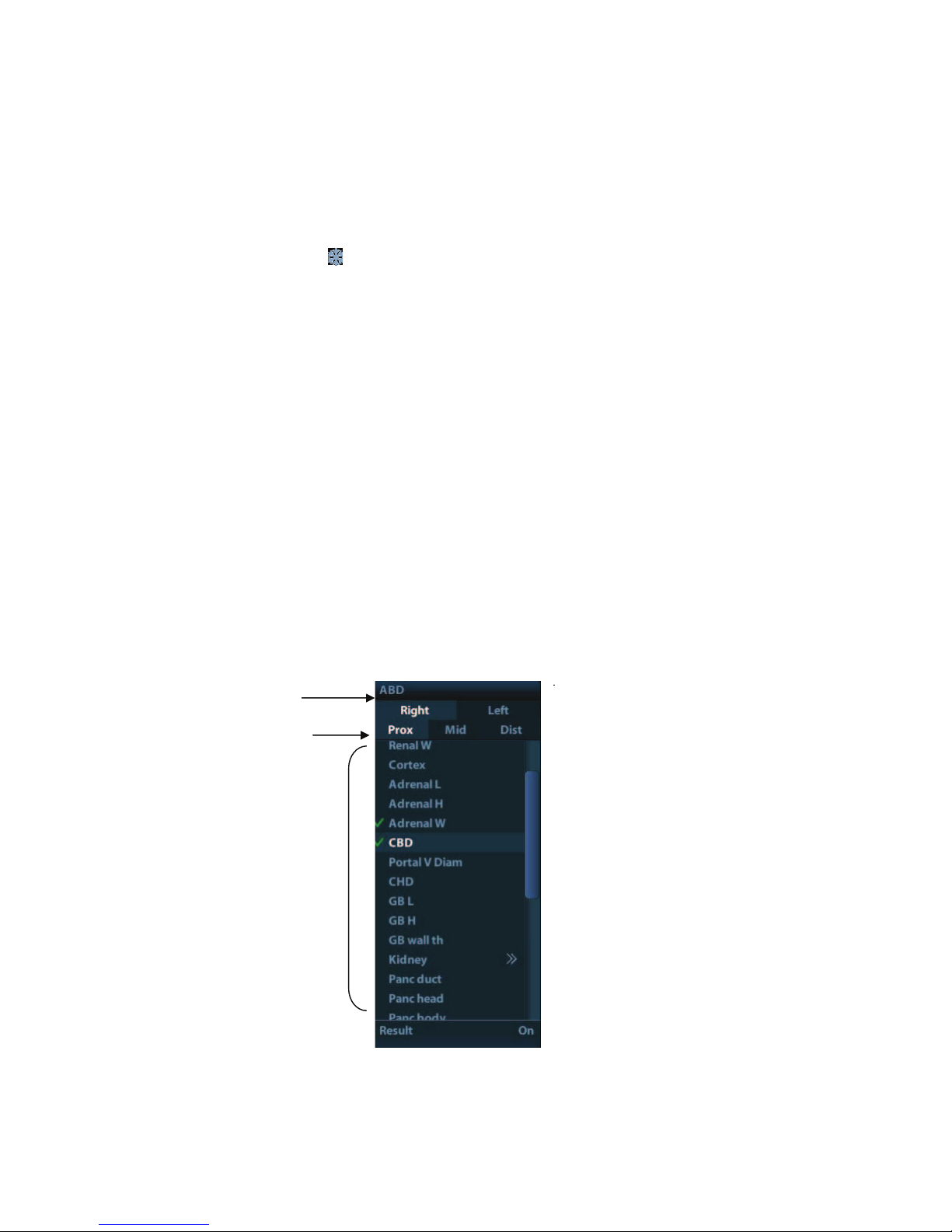
System Preparation 3-9
z Exam time
Displays the exam time, including date and time. Exam time can be set via [Setup]->
[System Preset]-> [Region]. Exam time will be frozen with the frozen image.
z Acoustic power & MI/TI
Displays the acoustic power. Including the acoustic power, MI (Mechanical Index)
and TI (Thermal Index).
z Freeze icon
The freeze icon
means the image is frozen.
z Animal Information
Displays animal name, ID, gender and age etc. Enter the animal information through
the "Animal Info" screen. Or, import the saved animal data from iStation or the
DICOM Worklist server.
z Probe model
Display the currently-used probe model, or the default model.
z Exam Mode
Displays the currently used exam type, e.g. Abdomen, is displayed.
z Operator
Displays the operator!s name on the screen. This information is entered through the
[Animal Info] screen.
z Accession#
The accession # indicates exam number used in hospital information system. It can
be imported via DICOM or input manually.
Menu area
Include image menu, measurement menu, comment menu, bodymark menu and so on.
Use the trackball or the multifunctional knob to operate on the menu.
To show or hide the image menu, press <Menu> key on the control panel.
The menu area consists of menu title, menu items. As shown in figure below.
h Menu title
Displays the menu name.
h Tags
Menu title
Tags
Items
Page 48

3-10 System Preparation
Attribute tags of the item.
h Items
Refers to the items on a menu. For item that is applicable for more than one mode,
the item appears as universal item in the certain mode. Items of image modes and
measurement can be preset (refer to "11 Setup" for details).
h Return to previous menu
Click [Return] to return to the previous menu from the sub menu.
The multifunction knob can be used to operate the menu. Press the know to open the
menu; rotate the know to navigate through the items one by one.
Depending on the item types, the multifunction knob can:
h For a commanding item or command optional item: press the knob to directly
activate the item.
h For a parameter item or ON/OFF item: press the knob to lock and select the item,
then rotate the knob to switch among the available values; press the knob again
to release and deselect the item.
h For an item with sub-menu: press the knob to extend the sub-menu, and the
cursor navigates to the first sub-item. At the same time, you can exit from the
sub-menu to the previous item by clicking [Return] in the sub-menu.
h For tag items in the menu: e.g. the !Right# and !Left# tag in the measurement
menu. Rotate the multifunctional knob to navigate the tag, and press the knob to
select the tag.
Parameter area
Displays the image parameters for the activating window. If there are more than one
imaging modes, the parameters are displayed by each mode. For detailed parameters
displayed in this area, please refer to the corresponding imaging mode (s).
Image area
The image area displays the ultrasound images, probe mark (or activating window mark),
time line (in M mode), coordinate axis (including depth, time, velocity/frequency), focus
position (located at depth axis in the form of
), besides, the annotation, bodymark,
measurement calipers, grayscale bar are also displayed here.
Thumbnail preview & Zoom Window (image-in-image)
In the zoom status, this area displays the thumbnail of a complete image, and a
rectangular frame is used to highlight the currently magnified area. This feature is called
image-in-image.
Help information area
The help information area displays various help information or progress bar in the current
status.
Besides, the system can provide help for each key. Press [Help] to enter key-help status,
you can see the cursor changes into an arrow with a question mark on it. Press any key
on the control panel, the screen displays the key-relevant information, meanwhile, the
system exits the key-help status.
Tips: in terms of help information, !TB# refers to !Trackball#, !Knob refers to Multifunction
knob.
Thumbnail area of images stored
Displays the thumbnail images stored under the current animal.
Image manage area
z Page-turning: when there are more than one page images have been stored, you can
turn to the next or preview page by
or respectively.
z Delete: select a thumbnail image , and click to delete it.
Page 49

System Preparation 3-11
z Send to: select a thumbnail image , and click
to send it to other devices.
System status icon
This area displays the relevant system icons, such as USB memory device, printer,
network, Chinese / English entry, and current system time, etc.
None-fixing Area
Position of areas illustrated here are not fixed, you can move them by the trackball within
a certain area on the display.
z Result window
The measurement result window displays the results of recently performed
measurements.
To move the result window:
a) Place the cursor on the title of result window (you can see the cursor changes
into
).
b) Press <Set> and move the trackball, the window moves together with the cursor.
c) Move the cursor to the target position, press [Set] again to anchor the result
window in the target position.
z Comment area
For details, please refer to !8 Comments and Body Marks".
z Body mark area
For details, please refer to !8 Comments and Body Marks".
3.11.2 Basic Operations of Screens
A screen consists of title, page tabs, contents and buttons, as shown in the following figure:
Composition Description
Title Bar
The title bar is used to give a description for the content and
function of the screen.
Title
Tab
Control
button
Contents
Page 50

3-12 System Preparation
Composition Description
Page Tab
For some screens, contents are distributed across several
pages. Use the selection pointer and <Set> key to
open/close the available pages. Use the selection pointer
and [Set] key to open / close the available pages.
Content
Radio button: click to select the item.
Check box: click to check or uncheck the item.
Entry box: enter characters manually via the keyboard.
Position the cursor into the box, and then enter the
letters or characters.
Drop-down list box: click [ź] to show the list and select
an item.
[OK] and [Cancel]
When the operation of a screen is complete, press the [OK]
or [Cancel] button to save or cancel the operation, and close
the screen.
To reposition a dialogue box:
1. Roll the trackball to move the cursor onto the title bar of the dialogue box. At this time the
cursor becomes a
; press the [Set] key.
2. Roll the trackball and reposition the rectangular graphic to the new desired location.
3. Press the <Set> key, and the dialogue box is moved to the desired position.
Page 51

Exam Preparation 4-1
4 Exam Preparation
CAUTION:
Before examining a new animal, press <End Exam> to end the
exam of the previous animal, update the animal information, to
avoid mixing data of the next new animal.
4.1 Start an Exam
You can start an animal exam in the following situations:
z New animal information: to start a new animal exam, enter the animal information first,
for details, please refer to !4.2.1 New Animal Information"; however, the system also
supports anonymous animal exam, in which you can take the exam without
registering animal information.
z New exam: to start a new exam for an already recorded animal, the recorded
information can be obtained either through iStation or Worklist, refer to #4.2.2.1
iStation#and #4.2.2.2 DICOM Worklist# for details.
z Activate an exam: select an exam that is ended within 24 hours, and continue the
exam with the imported animal information and exam data. For details, please refer
to !4.5 Activate& Continue an Exam".
z Continue an exam: select an exam that is paused within 24 hours, and continue the
exam with the imported animal information and exam data. For details, please refer
to !4.5 Activate& Continue an Exam".
General procedure for an exam: enter the animal information-> select an exam mode and
probe -> choose an imaging mode -> start the exam.
To start a new animal exam, it is better to enter the detailed animal information. The system
will set up a unique information database for each animal based on the animal information
entered, so that the information of one animal will not be confused with that of another animal.
4.2 Animal Information
To enter the #Animal Info# screen
z Press <Patient>, or,
z Move the cursor onto the animal information area on the display and press <Set> to
open the screen.
To exit the #Animal Info# screen
z Click OK on the #Animal Info# screen; or, press <Patient> on the control panel again,
to save the settings and exit the screen.
z Click [Cancel] or press <Esc> to exit the screen without saving any of the entered
animal data.
z Press <B> or <Freeze> to return to the current exam mode with the entered
information being saved.
Click [Quick Register] on the screen to save the animal information quickly and return to
the main screen.
4.2.1 New Animal Information
The Animal Info page is shown as below:
Page 52

4-2 Exam Preparation
Place the cursor onto the targeted box. The field box is highlighted and a flashing cursor
appears. Information can be entered or selected from the options.
You can also change the cursor position by <Tab>, <Enter> or up/down controls
Information includes:
1. General information
z Name
Enter animal name through the keyboard. Characters of A through Z and 0 through 9 and
!." are allowed. !\", !^", !˙" and !, " are not permitted.
z Animal ID
Animal ID is generated automatically by the system after starting a new animal, and can
be modified manually. Once you enter the ID and confirm it, you are not allowed to
change it.
NOTE: 1. !\" is not permitted.
2. If enter an ID that is already existed in the system, a warning !The ID
existed, load data" prompts, and you can import the animal data. The
animal data can be edited after importing.
z Animal
Select animal type.
z No.
Input the animal serial number.
z Host
Information of the animal owner.
z Gender
Select Male, Female or Unknown for animal gender in the drop down list.
z DOB (Date of birth):
h You can either enter the birth date of an animal manually;
3
1
2
4
Page 53

Exam Preparation 4-3
h Or, click
to select the date, and click [OK] to confirm.
z Age
h Auto generated age: once the DOB is gotten, the system can display an auto-
generated age in the field box, the unit can be !Years", !Months" or !Days". If the
age is less than one year, the system will automatically calculate the age in
months or days.
h Also, you can manually enter the age.
NOTE: When you enter the date manually, please enter it in the format as that of the
system.
2. Exam Type
z Exam application type
You can select among: ABD (Abdomen), OB (Obstetrics), GYN (Gynecology), CARD
(Cardiac), VAS (Vascular), URO (Urology), SMP (Small Part), and PED (Pediatrics).
Select the exam type tab to enter the exam-specific information.
z General information:
Study
description:
to enter description for each exam.
Primary
indications:
to enter the primary indications (reason to perform the
exam.)
Secondary
indications:
to enter the secondary indications.
CPT4 code: to enter the CPT4 code.
CPT4
description:
to enter the CPT4 description.
z Exam specified information:
Exam Type Information Description
ABD
(Abdomen)
Height
/
Weight
/
BSA (body
surface
area)
After the height and weight are inputted, the system will
automatically calculate the BSA based on the formula which
is set via [Setup]-> [System Preset]-> [General].
OB
(Obstetric)
Date
Select the index type and date.
z LMP: last menstrual period
z IVF: in vitro fertilization
z PRV: previous exam date
z BBT: basic body temperature
z EDD: estimated delivery dat
Gravida Times of pregnancy.
Ectopic Times of abnormal pregnancy. e.g. extrauterine pregnancy
Gestations Number of embryos (1~15; 1 is default)
Para Times of delivery
Aborta Times of abortion
GYN
LMP Last menstrual period
Page 54

4-4 Exam Preparation
Exam Type Information Description
(Gynecology)
Gravida Times of pregnancy.
Para Times of delivery
Ectopic Times of abnormal pregnancy. e.g. extrauterine pregnancy
Aborta Times of abortion
CARD
(Cardiac)
Height /
Weight /
BSA (body
surface
area)
After the height and weight are inputted, the system will
automatically calculate the BSA based on the formula which
is set via [Setup] -> [System Preset] ->[General].
BP Blood pressure.
HR /
RA Press Right Atrium Pressure
VAS
(Vascular)
BP(L) Input left blood pressure.
BP(R) Input right blood pressure.
URO
(Urology)
Serum PSA /
PPSA
coefficient
/
SMP (Small
Parts)
None /
PED
(Pediatrics)
None /
3. Operating Information
z Ref. Physician: the people who requires the operator to do the ultrasound operation.
!\", !^", !˙" and !," are not permitted.
z Diagnostician: people who is responsible for exam. !\", !^", !˙" and !," are not
permitted.
z Operator: people who is responsible for images collection and scanning. !\", !^", !˙"
and !," are not permitted.
z Accession #: exam number used in DICOM, “\” is not permitted.
z Comment: exam-specific explanation or remarks.
4. Functional key
z [New Animal]: click to clear the current animal information in the animal information
screen in order to input new animal information.
z [New Exam]: click to clear the current exam information in order to create a new
exam for the current animal.
z [Pause Exam]: to pause the current exam.
z [OK]: click to save the animal data entered and exit the screen.
z [Cancel]: click to cancel the animal data entered and exit the screen.
Page 55

Exam Preparation 4-5
4.2.2 Retrieve Animal Information
4.2.2.1 iStation
The animal data can be obtained in iStation from the system hardware or USB memory device.
You can enter the searching conditions for the animal.
1. To enter iStation screen (the screen is shown as follows):
z Press <iStation> on the control panel; or,
z Click [iStation] in the "Animal Info" screen; or
z Press the <Review> key on the control panel and click [iStation] in the screen.
2. Select the data source:
Select the data source in the drop-down list of "Data Source".
3. Input the searching condition:
Item: including Name, ID, DOB and Exam Date, the default one is name; then enter a
keyword in accordance with the Item selected.
z Select !Find in results#, the system will search the keyword based on the existed
searched results.
4. Select the desired animal information in the list. The following menu pops up:
Page 56

4-6 Exam Preparation
Button Function Description
Review
Image
Click to enter the Review screen.
Patient
Info
Click to enter the Animal Info screen.
Review
Report
Click to enter the Diagnostic Report screen.
Delete
Exam
Click to delete the selected record.
Backup
Exam
Click to export the selected animal data to media supported.
Restore
Exam
Click to import the animal data from an external media.
Send
Exam
Click to send the selected animal data to external device,
DICOM storage server or DICOM printer.
Active
Exam
Click to continue an exam finished within 24 hours.
Continue
Exam
Click to continue an unfinished exam carried out within 24
hours.
Other buttons:
z [New Exam]: Click to enter Animal Info screen, meanwhile, the corresponding animal
information is also imported to the new exam. After you edit the animal information in
the Animal Info screen, select [OK] to start a new exam.
z [Select All Exams]: Click to select all records.
z [Exit]: click to exit iStation.
4.2.2.2 DICOM Worklist
When the DICOM basic package is configured and the Worklist server has been set, click
[Worklist] in the "Animal Info" screen to query or import the animal data. (For the setting of
Worklist server, please refer to ಯDICOMರ.)
Procedure:
1. Select data source: choose a worklist server in the drop-down list of ಯWorklist Serverರ,
and then all the animal exam records in the server are listed out.
2. Input the searching condition:
z Select exam date period, click [Query] to search the animal data in the period.
z Enter animal ID, animal name, accession #, the system affords the result in real-time.
Page 57

Exam Preparation 4-7
z Or select the keyword type, enter the keywords and then click [Query] to search.
z To reset the criteria, click [Clear] button.
3. Select the desired animal from the list.
z Click [Start Exam], the animal information is imported into the system and then an
exam is started.
z Click [Transfer], the animal information is imported into the Animal Info screen. Edit
the animal information in the Animal Info screen, and select [OK] to start a new exam.
z Click [Show Detail] to see details of animal data.
4. Click [Exit] to exit the Worklist.
4.3 Select Exam Mode and Probe
CAUTION:
If the exam mode is changed during a measurement, all
measurement calipers on the image will be cleared. The data of
general measurements will be lost, but the data of application
measurements will be stored in the reports.
4.3.1 Supported Exam Modes
The system can be configured with the following exam modes.
The system supports to preset application type, measurements, comments, body marks,
image parameters for each exam mode(including user-defined exam modes). For details,
please refer to •11.2.2 Exam Configuration•.
You can select exam modes for the probes. For details, please refer to •11.2.1 Exam
Selection•.
4.3.2 Selecting Exam Mode and Probe
Select Probe and Exam Mode
(1) Press <Probe> to open the following dialog box.
Page 58

4-8 Exam Preparation
(2) Roll the trackball and press <Set> to select the exam mode, and use the direction
keys to turn pages of the exam modes.
To save the image parameters for the current exam mode quickly:
(1) Click [Save] to save the image parameters in the current image mode as presets. A
dialogue box pops up to prompt you the operation will cover the current image preset
data.
(2) Click [Save as] to save the current image parameters to the designated exam mode.
Click [Exam Preset] to enter the exam preset screen. For exam preset, please refer to
"11.2 Exam Preset".
Exit:
Click [Exit] or press <Probe> to exit, press <B>, <Freeze> or <ESC> can also exit the
screen.
4.3.3 Dual Probe Switching
You can preset user-defined key to implement switching probes between single B and 2B
mode. The function is only available to the probes of the same exam mode.
In single B mode: press the user-defined key to switch the current window between two
probes (with Cine Memory in [Image Preset] is set to !Split#)
In Dual B mode: press the user-defined key to switch two windows between two probes.
Preset the user-defined key via [Setup](by pressing <Setup>)-> [System Preset]-> >.H\
&RQILJ@
1. Select the user-defined key in the Key Function page on the left (Print, Save1, Save2,
F1~F4); or, select the key of footswitch.
2. Select •Dual Probe• in the page of Advanced Features on the right.
3. Click [OK] to confirm the setting and exit the dialog box.
4. After returning the preset, the setting will take effect.
Page 59

Exam Preparation 4-9
4.3.4 Bi-plane Endocavity Probe (65EB10EA)
When active the probe, system displays sagittal plane B-mode image by default, you can
switch the plane by clicking [Select Plane] on the menu to select the plane among S (sagittal)
Plane, T (transverse) Plane. The S and T plane are shown visually on the right side of the
screen.
Measurement, comment, and body mark functions are available when using this probe. Body
mark added to one plane will be displayed on both planes, and the probe orientation on one
plane is perpendicular to the other.
4.4 Selecting Imaging Mode
Use the corresponding key in the control panel to enter the imaging modes.
For the detailed operations in each imaging mode, please refer to !5 Image Optimization".
4.5 Activate& Continue an Exam
4.5.1 Activate an Exam
Select an exam finished within 24 hours, select the exam record, click from the menu
popped up; or, click [Active Exam] in !iStation" or !Review" screen to activate the exam.
Note:
z The system can automatically load the animal information and exam data to continue
the exam.
z If you want to continue an exam which data lies in an external memory database, you
have to first allow the system to load the animal data to the system#s animal database.
4.5.2 Continue an Exam
Select an exam paused within 24 hours, select the exam record in iStation screen,
click
from the menu popped up to continue the exam.
If you want to continue an exam which data lies in an external memory database, you have to
first allow the system to load the animal data to the systemಬs animal database.
4.6 Pause & End an Exam
4.6.1 Pause and Exam
Sometimes, you have to stop an uncompleted exam due to some special causes. When
the exam is paused, the system can begin other exams.
1. Press <Patient> to enter $Animal Info$ screen.
2. Click [Pause Exam].
If the system is powered off during scanning, the exam status turns $paused$ after the
system restart.
Only one exam can be paused every time.
When an exam is paused, the system will:
Page 60

4-10 Exam Preparation
1. Saves the exam-related images, reports and measurement data, modifies the status as
ಯPausedರ.
2. Save the exam information, including report, imaging mode, exam mode, image
parameters, operation mode, imaging / measurement data and so on.
4.6.2 End an Exam
Before examining a new animal, press <End Exam> to end the exam of the previous animal,
update the animal ID and information, to avoid mixing data of the next new animal.
To end an exam, you can do one of the following:
z Press <End Exam> on the control panel.
z Click [New Animal] on the Animal Info screen to end the last animal exam and clear
the animal information.
z Click [New Exam] on the Animal Info screen (or iStation screen, or Review screen) to
end the last exam and clear the exam data.
Page 61

Image Optimization 5-1
5 Image Optimization
WARNING:
1. The images displayed in this system are only reference for
diagnosis. :HDUH not responsible for the correctness of
diagnostic results. It is the responsibility of the clinician,
who performs the exam, to capture the correct diagnostic
results.
2. In Dual-B imaging mode, the measurement results of the
merged image may be inaccurate. Therefore, the results are
provided for reference only, not for confirming a diagnosis.
5.1 Switching Between Image Modes
Key Description
B Mode key: press to enter B mode
M Mode key: press to enter M mode
Dual-split display key: press to enter the Dual-split display mode, and press to
switch between the window
Switching key: Press to change the currently active window.
Press to enter the quad-split screen display, or switch image window in the
Quad mode.
5.2 Basic Operations
Before optimizing the image by adjusting image parameters, adjust the brightness and
contrast of the display to the best.
Requirement Available Operations
To modify the
brightness
Adjust [Gain].
Adjust TGC
Adjust [Acoustic Power] (try adjusting gain before
increasing the acoustic power)
Page 62

5-2 Image Optimization
Requirement Available Operations
To modify gray scale
image effect
Adjust [Dynamic Range]
Adjust [Map]
Adjust [Persistence]
Adjust [iClear] (optional)
To increase frame
rate
Decrease [Depth]
Decrease the [Focus Number]
Decrease the [FOV]
Decrease [Line Density]
Turn on [High FR] in harmonic mode
Adjusting through Image Menu:
Press <Menu> or multifunctional knob to open the menu; use the trackball and <Set> or
the multifunctional knob to adjust.
Adjusting through image parameter area:
The image parameter area is located in the upper right corner of the screen. The image
parameters are displayed while the image menu is not available.
(1) Move the cursor to the item on the parameter area.
(2) Press the <Set> key.
(3) Rotate the multifunctional knob to change the values.
Adjusting through control panel:
Trackball, control panel key, knob or sliders.
Adjusting through grayscale bar:
Move the cursor onto the grayscale bar, and press <Set> to switch among the gray maps.
5.3 B Mode
B mode is the basic imaging mode that displays real-time images of anatomical tissues and
organs.
5.3.1 B Mode Exam Protocol
1. Enter the animal information, and select the appropriate probe and exam mode.
2. Press <B> on the control panel to enter B mode.
3. Adjust parameters to optimize the image.
4. Perform other operations (e.g. measurement and calculation) if necessary.
In real-time scanning of all image modes, press <B> on the control panel to return to B mode.
5.3.2 B Mode Parameters
In B mode scanning, the image parameter area in the upper left corner of the screen displays
the real-time parameter values as follows:
Page 63

Image Optimization 5-3
Display F 2.5M D 21.3 G 100 FR 34 IP 1 DR 65
Parameter Frequency Depth Gain Frame Rate B IP B Dynamic
Range
Parameters that can be adjusted to optimize the B Mode image are indicated in the following.
Adjustment Items
Control Panel Gain, Depth, TGC, iTouch, Focus, Frequency, Dual, Quad
Menu
Frequency, iBeam, Gray Map, Focus Position, Focus Number,
Colorize, Colorize Map, FOV, IP, Dyn Range, Persistence, L/R Flip,
U/D Flip, Line Density, iTouch, Acoustic power, Smooth, High FR, TSI,
FOV Position, Rotation, HScale, Lithotrity, Gray Rejection, Ȗ, Curve,
Gray Invert
5.3.3 B Mode Image Optimization
Gain
Description To adjust the gain of the whole receiving information in B mode. The real-time
gain value is displayed in the image parameter area in the upper left corner of
the screen.
Operation Rotate the <Gain/iTouch> knob clockwise to increase the gain, and
anticlockwise to decrease.
Or adjust it in the image parameter area.
The adjusting range is 0-100.
Effects Increasing the gain will brighten the image and you can see more received
signals. However, noise may also be increased.
Depth
Description This function is used to adjust the display depth of sampling, the real-time
value of which is displayed on the image parameter area in the upper left
corner of the screen.
Operation Use the <Depth/Zoom> knob to adjust the depth;
Or adjust it in the image parameter area.
The adjustable depth values vary depending upon the probe types.
Effects Increase the depth to see tissue in deeper locations, while decrease the depth
to see tissue in shallower locations.
Impacts Depth increase will cause a decrease in the frame rate.
TGC
Description The system compensates the signals from deeper tissue by segments to
optimize the image.
There are 8-segment TGC sliders on the control panel corresponding to the
areas in the image.
Page 64

5-4 Image Optimization
Operation To increase the gain compensation at an area of interest, move the TGC slider
to the right. To decrease the gain compensation at the corresponding area of
interest, move the TGC slider to the left.
About 1.5s after the adjustment is finished, the TGC curve disappears.
Effects Adjust the signal gain for the certain image area to get a balanced image.
Frequency
Description This function is used to select the operating frequency of the current probe,
the real-time value of which is displayed in the image parameter area in the
upper left corner of the screen, where !F" represents B mode frequency, and
!FH" represents harmonic frequency.
Operation Adjust it through [Frequency] on the image menu, wherein !H" means the
harmonic frequency.
Or adjust it in the image parameter area.
Values of frequency vary depending upon the probe types. Select the
frequency according to the detection depth and current tissue characteristics.
Effects The higher the frequency the better the near field resolution but the worse the
force of penetration.
Harmonic imaging enhances near field resolution and reduces low-frequency
and large amplitude noise, so as to improve small parts imaging.
A. power
Description Refers to the power of ultrasonic wave transmitted by the probe, the real-time
value of which is displayed in the image parameter area in the upper left corner
of the screen.
Operation Adjust through the [Acoustic Power] item in the image menu;
The adjusting range is 7%-100% in increments of 3%.
Effects Generally, increasing the acoustic power will increase the brightness and
contrast of the image as well as the force of penetration.
Impacts You should perform exams according to actual situation and follow the ALARA
Principle.
Focus
Description
Refers to adjustment of focus of the ultrasonic beams, symbols as #
# of
which will be displayed on the right of the image.
Operation Adjust the focus number through the [Focus Number] in the menu;
Adjust the focus position through the [Focus Position] in the menu;
In B Mode, focus number can be switched among 1-4.
Effects The area that is focused will be of a higher contrast and resolution to provide
a much clearer image.
Impacts The greater the number of focus, the slower the frame rate to image.
Imaging Display Adjustment
Description More information can be obtained without moving the probe or changing the
sampling position.
Page 65

Image Optimization 5-5
Operation Change the scan range through the [FOV] item in the menu;
The system provided four levels of scan range: ExFOV, W, N, M1, M2.
You can get a much larger field of view when selecting a larger FOV, but the
frame rate will decrease.
B Steer This function is to steer the beam transmitted by the probe.
Steer the transmitting beam through the [B Steer] item in the menu;
The steering angles provided are: -6, 0, 6.
Trapezoid
imaging
Turn on or off the function through [Trapezoid] item in the menu.
You can define user-defined key for trapezoid function via [Setup]-> [System
Preset]-> [Key Config].
Impacts The B Steer and Trapezoid function are available only for linear probes.
Line Density
Description The function determines the quality and information of the image.
Operation Adjust through the [Line Density] item in the menu;
Levels: UH/ H/ M/ L.
Effects The higher the line density, the higher the resolution, and the lower the frame
rate.
Dynamic Range
Description This function is used to adjust the B image resolution to compress or expand
the gray display range.
The real-time dynamic range value is displayed on the image parameter area
in the upper left corner of the screen.
Operation Adjust through the [Dyn Ra.] item in the menu;
Or adjust it in the image parameter area.
The adjusting range is 30-220dB in increments of 5dB.
Effects The more the dynamic range, the more specific the information, and the lower
the contrast with more noise.
iClear
Description This function is used to increase image profile, so as to distinguish the image
boundary.
Operation Adjust through the [iClear] item in the menu;
The system provides 5 levels of iClear effects adjustment, off represents no
iClear is turned on, and the bigger the value the stronger the effect.
Effects The bigger the value the clearer the profile of the image.
Impacts This function is an optional module.
Smooth
Description Rejects image noise and makes images smooth.
Operation Adjust through the [Smooth] item in the menu;
The system provides 4 levels of smooth function, the bigger the value the
higher the smooth adjustment.
Page 66

5-6 Image Optimization
Persistence
Description This function is used to superimpose and average adjacent B images, so as to
optimize the image and remove noises.
Operation Adjust through the [Persistence] item in the menu;
The system provides 8 level of frame average adjustment, the bigger the
value the stronger the effect.
Effects Persistence can remove image noise to make details to be clearer.
Impacts Persistence increase may lead to signal missing.
Rotation/ Invert
Description This function provides a better observation for image display.
Invert To invert the image horizontally or vertically.
Click [L/R Flip] or [U/D Flip] in the menu to invert the image.
Rotation Rotate the image through the [Rotation] item in the menu.
Image can be rotated by the manners in angle of 0°, 90°, 180°, 270°.
When the image is rotated in the angle of 90° or 270°, the depth scale is
displayed on the upper part of the screen.
When you flip or rotate an image, the !M" mark will change its position on the screen; the M
mark is located in the upper left corner of the imaging area by default.
Impacts The function is available in real-time imaging, freeze or cine review status.
iBeam
Description This function is used to superimpose and average images of different steer
angles to obtain image optimization.
Operation Adjust through the [iBeam] item in the menu;
Off: no iBeam
On: maximum iBeam optimization
Effects Images after iBeam processing can be optimized with less spot noise and
higher resolution, so that more details for the structure are revealed.
Impacts iBeam is available only for linear probes, and it is not available when trapezoid
function is turned on.
Auto Merge
Description In the Dual-split mode, when the images of the two windows use the same
probe type, depth, invert status, rotation status and magnification factor, the
system will merge the two images so as to extend the field of vision.
Operation Turn on/ off the function through the [Auto Merge] item in the menu;
Impacts Available only for linear probes.
The function is available in real-time imaging, freeze or cine review status.
Gray Map
Description Adjusting grayscale contras to optimize the image.
Page 67

Image Optimization 5-7
Operation Select among the maps through the [Gray Map] item in the menu;
You can also adjust through the grayscale bar: move the cursor to the
grayscale bar and press <Set> on the control panel to adjust.
The system provides 8 gray maps to be selected among.
Impacts The function is available in real-time imaging, freeze or cine review status.
IP
Description IP is a combination of several image processing parameters, which is used for
a fast image optimization, the real-time group of which is displayed in the
image parameter area in the upper left corner of the screen.
The IP combination parameters include dynamic range, iClear, persistence,
and smooth.
Operation Select among the IP groups through the [IP] item in the menu;
Or adjust it in the image parameter area.
The system provides 8 groups of IP combinations, and the specific value of
each parameter can be preset.
Colorize and Colorize Map
Description Colorize function provides an imaging process based on color difference
rather than gray distinction.
Operation Turn on/ off the function through the [Colorize] item in the menu;
Select the colorize map through the [Colorize Map] item in the menu;
The system provides 16 colorize maps to be selected among.
Impacts The function is available in real-time imaging, freeze or cine review status.
TSI
Description The TSI function is used to optimize the image by selecting acoustic speed
according to tissue characteristics.
Operation Select among the TSI modes through the [TSI] item in the menu;
The system provided 4 ways of optimization for specific tissues: general,
muscle, fluid and fat.
iTouch
Description To optimize image parameters as per the current tissue characteristics for a
better image effect.
Operation Press <Gain/ iTouch> on the control panel, the iTouch symbol will display in
the image parameter area.
Click [iTouch] on the image menu to adjust gain in iTouch status among -12
through 12dB.
Click [iTouch Bright] on the image menu to adjust brightness in iTouch status
among -2 through +2.
Gray Rejection
Description This function is to reject image signals less than a certain gray scale, then the
rejected signal corresponding area turns black.
Page 68

5-8 Image Optimization
Operation Click [Gray Rejection] in the menu to adjust.
The adjusting range is 0-5.
Curve
Description To manually enhance or restrain the signal in the certain scale.
Operation Click [Curve] in the menu to open the dialogue box to adjust.
Drag the curve node to increase or decrease the gray scale information: drag
the node up to increase the information and down to decrease.
Ȗ
Description The Ȗ correction is used to correct non-linear distortion of images.
Operation Click [Ȗ] on the image menu to adjust.
The adjusting range is 0-3, increase the value, the image turns dark.
Gray Invert
Description Reverse the polarity of the image.
Operation Click [Gray Invert] to turn on or off the image inversion.
Impacts The gray rejection, curve, Ȗ and gray invert functions are available in real-time
imaging, freeze or cine review status.
These post process adjustments will not influence the cine review.
High FR
Description Increases the frame rate when being turned on in THI mode.
Operation In single B mode when THI is turned on, click the [High FR] item in the menu
to obtain images with high frame rates.
HScale
Description Display or hide the width scale (horizontal scale).
The scale of the horizontal scale is the same as that of vertical scale (depth),
they change together in zoom mode, or when the number of the image
window changes. The HScale will be inverted when image is turned up/down.
Operation Click [HScale] on the menu to display or hide the scale.
5.4 M Mode
5.4.1 M Mode Exam Protocol
1. Select a high-quality image during B mode scanning, and adjust to place the area of
interest in the center of the B mode image.
2. Press <M> on the control panel, and roll the trackball to adjust the sampling line.
3. Press <M> on the control panel again or <Update> to enter M mode, then you can
observe the tissue motion along with anatomical images of B mode.
4. During the scanning process, you can also adjust the sampling line accordingly when
necessary.
Page 69

Image Optimization 5-9
5. Adjust the image parameters to obtain optimized images.
6. Perform other operations (e.g. measurement and calculation) if necessary.
5.4.2 M Mode Parameters
In M mode scanning, the image parameter area in the upper left corner of the screen
displays the real-time parameter values as follows:
Display V 3 IP 6 DR 65 G 45
Parameter M Speed M IP M Dynamic Range M Gain
Parameters that can be adjusted to optimize the M Mode image are indicated in the
following.
Adjustment Items
Control Panel Gain, TGC, Depth
Menu
Frequency, Gray Map, Focus Position, Dynamic Range, Speed,
Display Format, Colorize, Colorize Map, IP, Edge Enhance, M Soften,
Time Mark, Acoustic Power, Gray Rejection, Ȗ, Curve, Gray Invert.
During M mode imaging, you can switch between B and M menu from the menu title.
During M Mode scanning, frequency and acoustic power of the transducer are
synchronous with that of B Mode.
Adjustment of the depth or TGC to the B Mode image will lead to corresponding changes
in M Mode image.
Press <Update> to switch between the real-time B and freezing B images.
5.4.3 M Mode Image Optimization
Gain
Description To adjust the gain of M mode image. The real-time gain value is displayed in the
image parameter area in the upper left corner of the screen.
Operation Rotate the <Gain/ iTouch> knob clockwise to increase the gain, and anti-
clockwise to decrease.
Or adjust it in the image parameter area.
The adjusting range is 0-100.
Effects Increasing the gain will brighten the image and you can see more received
signals. However, noise may also be increased.
Focus Position
Description
To change the focus position in M mode, symbols as "
" of which are displayed
on the right of the image.
Operation Adjust the focus position through the [Focus Position] item in the menu.
Time Mark
Description To show the time mark in M mode image.
Operation Turn on or off the function through [Time Mark] item in the menu.
Page 70

5-10 Image Optimization
Effects When time mark is displayed on the M mode image, it's much easier to identify
the cardiac cycles and detect more details.
Impacts The function is available in real-time imaging, freeze or cine review status.
Display Format
Description To set the display format of M mode image with B mode image.
Operation Adjust through the [Display Format] item in the menu;
There are 4 formats available for the images display: L/R, V1:1, V1:2, Full.
Effects Adjust according to the actual situation and obtain a desired analysis through
comparison.
Impacts The function is available in real-time imaging, freeze or cine review status.
Speed
Description This function is used to set the scanning speed of M mode imaging, and the
real-time speed value is displayed in the image parameter area in the upper
left corner of the screen.
Operation Change the speed through the [Speed] item in the menu;
Or adjust it in the image parameter area.
There are 6 levels of scan speed available, the smaller the value the faster the
speed.
Effects Speed changing makes it easier to identify disorders in cardiac cycles.
IP
Description IP is a combination of several image processing parameters ,which is used for a
convenient image optimization. The IP combination number is displayed on the
image parameter area on the right part of the screen.
The M IP combination parameters include dynamic range and M soften.
Operation Select among the IP groups through the [IP] item in the menu;
Or adjust it in the image parameter area.
The system provides 8 groups of IP combinations, and the specific value of
each parameter can be preset.
Colorize and Colorize Map
Description Colorize function provides an imaging process based on color difference rather
than gray distinction.
Operation Turn on or off the function through the [Colorize] item in the menu;
Select the colorize map through the [Colorize Map] item in the menu;
The system provides 16 different maps to be selected among.
Impacts The function is available in real-time imaging, freeze or cine review status.
Gray Rejection
Description This function is to reject image signals less than a certain gray scale, then the
rejected signal corresponding area turns black.
Operation Click [Gray Rejection] on the image menu to adjust.
The adjusting range is 0-5.
Page 71

Image Optimization 5-11
Curve
Description To manually enhance or restrain the signal in the certain scale.
Operation Click [Curve] in the menu to open the dialogue box to adjust.
Drag the curve node to increase or decrease the gray scale information: drag
the node up to increase the information and down to decrease.
Ȗ
Description The Ȗ correction is used to correct non-linear distortion of images.
Operation Click [Ȗ] on the image menu to adjust.
The adjusting range is 0-3.
Gray Invert
Description Reverse the polarity of the image.
Operation Click [Gray Invert] to turn on or off the image inversion.
Impacts The gray rejection, curve, Ȗ and gray invert functions are available in real-time
imaging, freeze or cine review status.
These post process adjustment will not influence the cine review.
Gray Map
Description Adjusting grayscale contras to optimize the image.
Operation Select among the maps through the [Gray Map] item in the menu;
You can also adjust through the grayscale bar: move the cursor to the grayscale
bar and press <Set> on the control panel to adjust.
The system provides 8 gray maps to be selected among.
Impacts The function is available in real-time imaging, freeze or cine review status.
Edge Enhance
Description This function is used to increase image profile, so as to distinguish the image
boundary.
Operation Adjust through the [Edge Enhance] item in the menu;
The system provides 14 levels of edge enhance effects, off represents no edge
enhance is turned on, and the bigger the value the stronger the effect.
Impacts Larger edge enhance may lead to noise increasing.
Dynamic Range
Description Adjusts contrast resolution of an image, compresses or expands gray display
range. The real-time dynamic range value is displayed on the image parameter
area in the upper left corner of the screen.
Operation Adjust through the [Dyn Ra.] item in the menu;
Or adjust it in the image parameter area.
The adjusting range is 30-220dB in increments of 5dB.
Effects The more the dynamic range, the more specific the information, and the lower
the contrast with more noise.
Page 72

5-12 Image Optimization
M Soften
Description This feature is used to process the scan lines of M images to reject noise,
making the image details to be clearer.
Operation Adjust through the [M Soften] item in the menu;
The system provides 14 levels of M Soften adjustment, the bigger the value the
stronger the effect.
5.5 Image Preset
5.5.1 Image Preset
The image preset is used to set image parameters for a specific transducer in a specific exam
type. The setting methods are similar although parameter items are different in each image
mode.
1. Press <Setup> on the keyboard.
2. Select [Image Preset]Æ[B/THI] to enter the B-mode parameters preset, as shown in the
following figure.
3. Select an exam mode and probe.
z Select !ABD" (Abdomen) from the drop-down list of !Exam Mode".
z Select !35C50EA" (for example) from the drop-down list of !Probe".
4. Image parameter preset
z The [ABD-- All Probe] field on the left side of the screen displays the parameter
preset for all probes in ABD exam mode.
Page 73

Image Optimization 5-13
General Parameter
A.power Drop-down list To set the default acoustic power.
Thermal index Radio button
TIC, TIB, TIS, to choose the item to be displayed on the
screen.
Colorize Check box
To set the default status of colorize function in B mode,
to turn on or off.
Colorize Map Drop-down list To set the default colorize map in B mode.
TSI Drop-down list To set the default TSI mode for B mode.
iTouch Drop-down list To set the default gain of iTouch in B mode.
iTouch Bright Drop-down list To set the default brightness of iTouch.
z The [ABD-35C50EA] field on the right side of the screen displays the parameter
preset for the35C50EA probe in ABD exam mode.
Probe Specific Items
Depth Drop-down list To set the default depth in B Mode.
Frequency Drop-down list To set the default frequency of the transducer.
FOV Drop-down list To set the default FOV in B Mode.
Focus Position Drop-down list To set the default focus position in B Mode.
Focus Number Drop-down list To set the default focus number in B Mode.
Steer Drop-down list
To set the default steer angle for the linear probe in
B mode.
Trapezoid Check box
To set if trapezoid function is default to be open for
linear probe in B mode.
Line Density Drop-down list To set the default line density in B Mode.
B Gain Drop-down list To set the default gain value in B Mode.
THI Gain Drop-down list To set the default THI gain value in B Mode.
B Gray Map Drop-down list To set the default gray map in B Mode.
THI Gray Map Drop-down list To set the default THI gray map in B Mode.
iBeam Drop-down list
To set the default iBeam value for the linear
transducer in B Mode.
L/R Flip Radio button
To set the default horizontal flipping mode: Left or
Right.
U/D Flip Radio button
To set the default vertical flipping mode: Up or
Down.
Rotation Drop-down list To set the default rotate status in B Mode.
B IP Drop-down list
To set the default B IP value and you can preset
each parameter in the button.
THI IP Drop-down list
To set the THI IP parameters and you can preset
each parameter in the button.
High FR Check box To set if high FR is turned on by default.
Page 74

5-14 Image Optimization
Probe Specific Items
iClear Drop-down list To set default value of iClear.
5. Click [OK] to exit.
Click [OK] to confirm and exit, or click [Cancel] to exit without saving.
Page 75

Display & Cine Review 6-1
6 Display & Cine Review
6.1 Image Display
6.1.1 Splitting Display
The system supports dual-split (B/B) and quad-split (4B) display format. However, only one
window is active.
z Dual-split: press <Dual> key on the control panel to enter the dual-split mode, and
using <Dual> key to switch between the two images; press <B> on the control panel
to exit.
z Quad-split: press <Quad> key on the control panel to enter the dual-split mode, and
using <Quad> key to switch between the two images; press <B> on the control panel
to exit.
6.1.2 Image Magnification
NOTE: Zooming an image changes the frame rate which tends to change thermal indices.
The position of the focal zones may also change which may cause the peak
intensity to occur at a different location in the acoustic filed. As a result, the MI may
change.
6.1.2.1 Spot Zoom
Procedures:
1. Enter zoom:
In real-time image scanning, press <Depth/Zoom> knob on the control panel to light the
Zoom indicator.
2. Adjust ROI:
Roll the trackball to change the box size and position, press <Set> to toggle between
setting the size and position. And after sample volume is set, press <Zoom> key again to
enter spot zoom status.
3. Exit:
In spot zooming status, press <Depth/Zoom> again.
Note:
z Spot zooming only can be realized on a scanning image.
z The size and position of sample volume box will be changed along with scanning
depth and area.
6.1.2.2 Pan Zoom
Procedures:
1. Enter Zoom:
Freeze the image, press <Depth/Zoom> knob on the control panel to light the Zoom
indicator. Image-in-image is displayed.
Page 76

6-2 Display & Cine Review
2. Rotate <Depth/Zoom> knob to change the magnification factor among 0.8-10.
3. Exit:
z Press <Depth/Zoom>.
z Unfreeze the image, the system exit pan zooming status automatically.
6.1.2.3 iZoom (Full-screen Zooming)
Function: to magnify the image in full screen.
According to the region to be zoomed, the system supports two types of full-screen
zooming:
z Zoom in the standard area to full-screen, including image area, parameter area,
image banner, thumbnail area and so on.
z Zoom in the image area only to full-screen.
Procedures:
1. Set the User-defined key:
(1) Press <Setup> to enter [Setup] -> [System Preset] -> [Key Config].
(2) Select a function-free key in the function list.
(3) Select "iZoom" in the "Other" page.
(4) Click [OK] to complete the setting.
2. Open the image(or the under scanning image), press the user-defined iZoom key once to
zoom in the standard image area; and then press the key again to zoom in the image
area only.
3. Press the user-defined key again to return to normal status.
The iZoom status supports:
z Measurements, adding comments and body marks.
z Video output, saving image and printing the current area that is zoomed in.
z Exiting the zooming status by pressing <Probe>, <Patient>, <iStation>, <Review> or
<Setup>.
6.1.3 Freeze/ Unfreeze the Image
Press <Freeze> on the control panel to freeze a scanning image. In freeze mode, the probe
stops transmitting acoustic power, and all images as well as the parameters are kept still.
Tip: after freezing an image, the system may enter cine review, measure, comment adding, or
body mark mode, which is dependent upon preset. (Setting path: [Setup]ൺ[System Preset]ൺ
[Image Preset]ൺ"Freeze Config")
Press <Freeze> in freeze mode to unfreeze the image, the system continues image scanning.
6.1.3.1 Imaging Mode Switching When Frozen
Imaging mode switching in freeze mode follows the following principles:
z In splitting display B mode, press <B> to exit splitting display mode and display the
image of the currently activated window in full screen.
z In freeze mode, the system supports imaging mode switching between the sub-
modes (only for the activated window).
z The imaging mode and parameters of an unfrozen image is the same as the
corresponding one that before frozen; but the display format is the same as the one
before unfrozen.
Page 77

Display & Cine Review 6-3
6.1.3.2 Imaging Display Format Switching When Frozen
Image display format switching in freezing mode follows the following principles:
2D᧧M (Press <Freeze> in 2D᧧M scanning mode)
If the imaging mode before frozen is 2D (frozen) +M (real time) or 2D (real time) +M
(frozen), then in freeze mode, you can switch between 2D(real time)+M(real time) or
2D(frozen)+M(real time)) by pressing <Update> key on the control panel.
Dual/quad splitting display mode (Press <Freeze> key in dual/quad splitting display mode)
z When enters freeze mode, the default activated window is the real-time window
before frozen. Other image windows display the corresponding cine memories, if a
certain cine memory is empty, then no image is displayed.
z Press <Dual> or <Quad> to switch between dual-splitting and quad-splitting modes.
z Press <B> button on the control panel to enter the single display format, which
displays the currently activated window. In single display format, press <Dual> or
<Quad> to switch between dual-splitting and quad-splitting mode.
z Unfrozen: in splitting display status, when you unfreeze the image you can only
unfreeze the image in the activated window, other images still keep frozen. In singlewindow display status, the system displays single image after being unfrozen.
6.2 Cine Review
After you press the [Freeze] key, the system allows you to review and edit the images prior to
the image frozen. This function is called as cine review. The magnified images can also be
reviewed after <Freeze> is pressed, and the operating method is the same. You can perform
post process operations, measurements, adding comments and body marks on the images
being reviewed.
The system supports manual review as well as automatic review. The default mode is Manual
Cine, but you can switch between Auto Cine and Manual Cine.
In addition, the system supports the images reviewed along with physiological waveforms, if
the detection of physiological waveforms is performed.
CAUTION:
1.
Cine Review images can be inadvertently combined inbetween separate animal scans. The cine memory must be
cleared at the end of the current animal and the onset of the
next new animal by selecting the <End Exam> key on the
control panel.
2.
Cine files stored in the systemಬ
s hard drive shall contain
animal information, to avoid the selection of an incorrect
image file and potential misdiagnosis.
6.2.1 Entering/ Exiting Cine Review
To enter cine review:
z Enter "[Setup]-> [System Preset]-> >Image Preset]-> “Freeze Config”, to set "Status
after Freeze" to be "Cine". Then the system enters the manual cine review status
once press <Freeze> to freeze the image.
z Open cine files in thumbnail, iStation or Review, the system enters automatic cine
review status.
To exit cine review:
z Press <Freeze> key again, the system will return to image scanning and exit cine
review.
Page 78

6-4 Display & Cine Review
z Press <Cine> or <Esc>, the images are still frozen but the system exits cine review.
6.2.2 Cine Review in 2D Mode
Manual cine review
After entering the cine review of 2D mode, rolling the trackball or rotating the
multifunctional knob will display the cine images on the screen one by one.
If you roll the trackball to the left, the review sequence is reversed to the image-storing
sequence, thus the images are displayed in descending order. Whereas, if you roll the
trackball to the right, the review sequence is the same as the image-storing sequence,
thus the images are displayed in ascending order. When the reviewing image reaches the
first or the last frame, further rolling the trackball will display the last or first frame.
The cine progress bar at the bottom of the screen (as shown in the figure below):
Auto Review
z Reviewing all
In the manual cine review, click [Auto Play] in the menu to activate auto cine review.
z Setting Region of Auto Review
You can set a segment of cine loop which can be reviewed automatically. After the auto
review region is set, the auto cine review can only be performed within this region; but the
manual cine review can be performed beyond this region. When the cine file is saved,
only the images within this region are saved.
a) Set first frame: Manually review the images until the frame which you want to set it
as start point, then click [Set First Frame] to set a start mark.
b) Set end frame: Manually review the images until the frame which you want to set it
as end point, then click [Set End Frame] to set an end mark.
c) Click [Auto Play] on the image mane.
d) Click [Auto Play] again or roll the trackball to enter manual review status; or press
<Cine> to exit cine reviewing.
e) Click [Skip to First]/ [Skip to Last] to review the first or last image.
Tips: you can perform cine review on each image window in the dual/ quad splitting
mode.
6.2.3 Cine Review in M Mode
After entering the cine review of M mode, rolling the trackball or rotating the multifunctional
knob will display the cine images on the screen one by one.
Roll the trackball to the left, the review progress slider moves to the left, the images moves to
the right, and the earlier stored images are invoked. Whereas, roll the trackball to the right,
the review progress slider moves to the right, and the images move to the left, the recently
stored images are invoked. When you review the images until the earliest or the latest frame,
further rolling the trackball will display the last or first frame.
The cine progress bar at the bottom of the screen (as shown in the figure below):
Start mark
Cursor
End mark
Current frame/ Total frames
Page 79

Display & Cine Review 6-5
Cine review operations are the same as those of 2D mode.
6.2.4 Linked Cine Review
The linked cine review refers to review of the images captured at the same moment.
There displays the frame mark
on the time mark of M image indicating the current 2D
image.
In dual or quad split display mode, you can only review images of the current active window,
use <Dual> or <Quad> to switch the window.
6.3 Cine Memory
6.3.1 Cine Memory Setting
There are 2 ways of cine memory split: auto and split.
Setting path: select "Auto" or "Split" for cine memory in [Preset]ൺ [System Preset]ൺ [Image
Preset].
Where,
z "Auto" for the cine memory indicates the system splits the cine memory as per the
number of B image windows.
z ಯSplitರ indicates the system always splits the cine memory, even if in the single-B
window, the system splits the cine memory into two as well. You can press <B> key
to switch and display the images in either memory, so you can compare images in
Split mode.
The memory capacity is evenly distributed as per splitting number, as shown in the following
table (Taking B images in low density as an example, the capacity of B cine memory is N
frames):
Imaging
Mode
Split
Single-B Dual Quad
Auto
One memory, with
capacity N frames.
The memory splits
into two, with
capacity N/2 frames
each
The memory splits
into four, with
capacity N/4 frames
each
Split
The memory splits
into two, with
capacity N/2
frames each
The memory splits
into two, with
capacity N/2 frames
each
The memory splits
into four, with
capacity N/4 frames
each
6.3.2 Cine Memory Clear
In the following conditions, the cine review memory will be cleared:
Time played Time in all
Start mark
End mark
Cursor
Page 80

6-6 Display & Cine Review
z Start an exam of a new animal.
z Start a new exam for the same animal.
z Switching the probe (if the cine memory is split, only the cine memory corresponding
to the currently activated window is cleared)
z Changing the exam condition (if the cine memory is split, only the cine memory
corresponding to the currently activated window is cleared)
z Imaging Mode Switching: include imaging mode switching among B, M, display mode
switching etc.
z Parameters modification, including:
h Parameters that can result in imaging region or direction changing, such as
depth, FOV, trapezoid, steer, zoom and so on.
h Parameters that can result in image frame changing, such as line density, focus
number and so on.
h Change speed in M mode
h 2D image cleared
z Unfreeze the image: after the image is unfrozen, images stored in the cine memory
will be cleared, but if the cine memory is split, only the currently cine memory
corresponding to the activated window will be cleared.
z Open/ close the image file that occupies cine memory.
6.4 Preset
Open [Setup] ė[System Preset]ė[General] to preset the cine storage length.
Clip length: 1~60s.
Page 81

Measurement 7-1
7 Measurement
There are general measurement and application measurement. You can perform
measurements on a zoomed image, cine reviewing image, real-time image, or a frozen image.
For measurements details, please refer to the [Advanced Volume].
WARNING:
Be sure to measure areas of interest from the most optimal
image plane to avoid misdiagnosis from inaccurate
measurement values.
CAUTION:
1.
If an image is unfrozen or the mode is changed during a
measurement, the calipers and measurement data will be
cleared from the screen. The general measurement data will
be lost (the application measurement data are stored in the
report).
2.
If the system is turned off or <End Exam> is pressed during
a measurement, the data not saved will be lost.
3.
In Dual-B imaging mode, the measurement results of the
merged image may be inaccurate. Therefore, the results are
provided for reference only, not for confirming a diagnosis.
7.1 Basic operations
Entering/Exiting Measurement
Enter: on the control panel, press the <Caliper> to enter general measurement; press
[Measure] key to enter application measurement.
Press <Caliper> or <Measure> key again to exit.
Measurement result and help information
The system displays and updates measurement results in the result window.
The help information concerning measurement and calculation is displayed in the Help
Information area at the bottom of the screen.
7.2 General Measurements
7.2.1 2D General Measurements
2D general measurements refer to general measurements on 2D mode:
Measurement Tools Function
Distance Measures the distance between two points of interest.
Depth
The distance between probe surface and the probing point along
ultrasound beam.
Angle The angle between two intersected planes.
Area Measures the area and perimeter of a closed region.
Page 82

7-2 Measurement
Measurement Tools Function
Volume The volume of a target.
Cross Line
The length of two line segments, which are perpendicular to each
other.
Parallel Line The distance between each pair of parallel lines in a sequence.
Trace Length Measures the length of a curve on the image.
Distance Ratio
Measures the lengths of any two line segments and the calculated
ratio.
Area Ratio The areas of any two regions and the calculated ratio.
B histogram
The grayscale distribution of ultrasonic echo signals in a closed
region.
B profile The grayscale distribution of ultrasonic echo signals across a line.
7.2.2 M General Measurements
M general measurements refer to general measurements on M mode. The measurements
listed below can be performed:
Measurement
Tools
Function
Distance The vertical distance between two points.
Time The time interval between any two points.
Slope
Measures the distance and time between two points and calculates the
slope.
HR
Measures the time of n (n8) cardiac cycles and calculates the heart rate in
M mode image.
Velocity
Calculates the average velocity by measuring the distance and time
between two points.
7.3 Application Measurement
The system support following measurement types:
Page 83

Measurement 7-3
Abdomen measurements - Used for measurements of abdominal organs (liver, gall
bladder, pancreas and kidney, etc.) and large abdominal vessels.
OB measurements- Used for measurements of animal growth indice.
Cardiac measurements- Used for left ventricle function measurements and
measurements of main artery and vein parameters, etc.
Gynecology measurements - Used for the uterus, ovary and follicles, etc.
Small Part measurements – Used for small parts such as thyroid.
Urology measurements - Used for urological organs measurements.
Vascular measurements – Used for vessels measurements.
Orthopedics measurements - Used for hip joint measurement.
Nerve measurements – Used for nerve structure measurements.
7.4 Measurement Accuracy
Table 1 Error of 2D Images
Parameter Value Range Error
Distance Full screen
Within ±3%; or when the measured value is less
than 40 mm, the error is less than1.5 mm.
Area (Trace) Full screen
Within ±7%; or when the measured value is less
than 16 cm
2
, the error is less than 1.2 cm2.
Area (ellipse,
circle)
Full screen
Within ±7%; or when the measured value is less
than 16 cm
2
, the error is less than 1.2 cm2.
Angle Full screen Within ±3%.
Table 2 Volume Measurements
Parameter
Value
Range
Error
Volume Full screen
Within ±10 %; or when the measured value is less than 64 cm
3
,
the error is less than 6.4 cm
3
.
Table 3 Time/Motion Measurements
Parameter Value Range Error
Distance Full screen
Within ±3 %; or when the measured value is less
than 40mm, the error is less than 1.5mm.
Time Timeline Display Within ±2%.
Heart rate Timeline Display Within ±4%.
Slope Timeline Display Within ±4%.
NOTE: Within the selected field range, the measurement accuracy is ensured within the
range mentioned above. The accuracy specifications are performance in the worst
conditions, or based on the real test for the system, regardless of acoustic speed
error.
Page 84

Page 85

Comments and Body Marks 8-1
8 Comments and Body Marks
8.1 Comments
Comments can be added to an ultrasound image to bring attention, notate or communicate
information observed during the examination. You can add comments to: zoomed image, cine
review image, real-time image, frozen image. You can type the character as comments; insert
the pre-defined comments from the comment library; or insert arrow markers.
WARNING:
You must ensure that the entered comments are correct.
Incorrect comments may cause misdiagnosis!
8.1.1 Comment Basic Procedures
1. To enter comment status:
z Press the [Comment] key to enter the comment status, and the cursor becomes !|".
z Press any alphanumeric key, and the corresponding letter or numeral is displayed
besides the cursor.
z Press the <Arrow> key to enter the arrow-adding status.
Tips: when the system entered comment status, the default characters entered are uppercase.
You can see the <Caps Lock> indicator lights on.
2. Place the cursor to the desired place to set the comment location. Add new comment to
the image according to actual situation. Here, you can modify, move, delete, hide or
display the completed comments.
3. To exit comment status:
z In the comment status, press <Comment> key.
z Or press <ESC> or other operating mode keys, such as [Caliper], [Measure] etc.
z In the arrow-adding status, press the <Arrow> key.
8.1.2 Comment Menu
You can adjust relevant settings in comment status via menu.
Display or hide the menu
After entering the comment status, pressing the <Menu> key or the multifunctional knob
will show or hide the Comment Text Library menu.
Home of comments
Assign the user-defined key for the set home function in ![Setup] ĺ [System Preset] ĺ
[Key Config]".
Move the cursor to the desired location for a comment and click the Set-Home userdefined key. The current position of the cursor is set to be the default position of the
comment adding. When clicking [Home], the cursor will turn to the default setting position.
Change Font Size/Arrow Size
z Click [Font Size] to change the font size of comment: Small, Mid, Big.
z Click [Arrow Size] to change the arrow size of comment: Small, Mid, Big.
Page 86

8-2 Comments and Body Marks
The default is the comment text library in the current exam mode. When entered the comment
status, the system displays the customized comment text library for the current exam. If there
is no customized comment text library for the current exam, it will display the comment text
libraries of all the exam modes assigned for the current probe. And if no text library for all the
exam modes is customized, no comment text will be displayed.
Please refer to •11.6 Comment Preset• for comment preset for the specific exam mode.
ABC Display
Click [ABC Display] to display or hide the added comments. Assign the user-defined key
for the function in •[Setup]-> [System Preset]->•Key Config• •.
8.1.3 Adding Comments
The system can be configured with comment text libraries including Abdomen, Cardiology,
GYN(Gynecology), OB(Obstetrics), Urology, SMP(Small Part), Vascular, PED(Pediatric) and
Nerve Blocks.
Typing comment characters
1. To set the comment location:
Roll the trackball or press direction-control keys on the keyboard to move the cursor to
the desired location for comments.
2. To type the alphanumeric characters:
z Type the alphanumeric characters through the qwerty (The default characters are
uppercase);
z To type the upper characters, press [Shift] and the character key at the same time.
3. Move to a new line:
In the edit status (the characters are in green color), press <Enter> to move the cursor to
the new line, and the location of the cursor is aligned with that of the first line.
4. In the edit status, move the trackball or press the multifunctional knob to confirm the
character added, and the color of the character added turns yellow.
Adding a Comment Text
Move the cursor onto the desired comment text in the menu and press <Set> or the
multifunctional knob, and then the system adds the selected comment text on the set
location. The added comment text is in the edit status, so you can edit the comment
text added.
z Add combined comment: Press <Menu> or the multifunctional knob to show the
menu; rotate the knob to view the comments one by one; press the knob again to add
the selected item onto the image(comment added in an editable state); rotate the
multifunctional knob to search for the next part, and press the knob again to add the
second part of the combined comment. Repeat procedures to add other parts of a
combined comment. Press <Set> to complete the comment.
Adding an Arrow
You can add an arrow to a location where you want to pay attention.
1. Press the <Arrow> key, and an arrow will appear at the default position.
2. Adjust the arrow
z Adjust the position and orientation of the arrow: roll the trackball to the desired
position and use the multifunctional knob to change the orientation in 15° increments.
z Click [Arrow Size] on the menu to change the arrow size:
3. Press <Set> or <Enter> to anchor the arrow position, and then the arrow turns yellow.
4. Repeat the above steps to add more arrows.
Page 87

Comments and Body Marks 8-3
5. Press <Arrow> key, <ESC> or to exit the arrow comment status.
8.1.4 Moving Comments
1. Move the cursor onto the comment that needs to be moved. Press <Set> to select it,
where a highlighted box appears around the comment.
2. Roll the trackball to move the comment to the new position.
3. Press the <Set> key to anchor the comment in the new position, and the commentmoving operation is complete.
8.1.5 Editing Comments
Modifying (Editing) characters
1. Move the cursor onto the comment that needs to be modified.
z Directly enter the character at the position that the cursor stays; or,
z Double press the <Set> key to enter the edit status, use the or key to
move the cursor to a location where needs to insert characters, and type characters.
2. Press the <Del> key to delete the comment character or text on the right side of the
cursor; Press the <Backspace> key to delete the comment character or text on the
left side of the cursor.
3. Roll the trackball or press the <Set> key or the multifunctional knob to confirm the
modification and to exit the edit status, and the color of the comments turns yellow.
Modifying (Editing) Arrows
1. Move the cursor on the arrow that needs to be modified. After the cursor turns to
,
press the <Set> key. The color of the current arrow turns green, and there is green
frame around the arrow, indicating the arrow can be edited. Move the cursor to
change the arrow position.
2. Rotate the multifunctional knob to modify the arrow direction.
3. Press the <Set> or <Enter> key to complete the modifying operation.
8.1.6 Deleting Comments
Deleting Comment Characters, Texts or Arrows
1. Move the cursor to the comment to be deleted.
2. Press the <Set> key to select the comment.
3. Press the <Del> or <Clear> key to complete the deleting operation.
Deleting a recently-added character, text or arrow
After you add several comments and the cursor is in the !|" or !
" status, pressing
<Clear> can delete the recently-added or recently-edited comment.
Erase All Text
Long press the <Clear> to delete all the comments.
NOTE: 1. When no object is selected, pressing the <Clear> key will clear all
comments and all measurements calipers.
2. After powering off, the system will clear all comments on the image.
Page 88

8-4 Comments and Body Marks
8.2 Body Mark
The Body Mark (Pictogram) feature is used for indicating the exam position of the animal and
transducer position and orientation.
The system supports body marks for Dog, Cat, Equine, Bovine, Ovine or Other. You can
preset the system configured general body marks for each exam mode, also, you can
customize the body mark. For details, please refer to !11.5 Body Mark Preset".
8.2.1 Body Mark Operation Procedures
To add the first body mark:
1. Press <Body Mark> to enter the body mark status.
2. Select the body mark, adjust the position and direction of the probe icon.
3. Exit body mark mode˖
z Press the <Set> key to confirm the position and orientation of the probe marker and
exit the body mark mode.
z Press [Body Mark] again on the control panel.
z Press the [Esc] key to confirm the current operation and exit the body mark status.
8.2.2 Menu
Press <Menu> to display the body mark menu. You can:
Select Bodymark library
Move the cursor to menu title, and select the desired library.
Display
Click [Display] to display or hide the body mark added.
8.2.3 Adding Body Marks
To add the first body mark:
(1) Enter body mark mode˖
(2) Select the bodymark library through the menu title.
(3) Select the bodymark.
Move the cursor onto the desired bodymark to highlight your choice, and press <Set>
to add the selected bodymark; or rotate the multifunctional knob to view the
bodymarks.
(4) Press <Set> to confirm the selection.
(5) To adjust the probe position and orientation marker:
z Roll the trackball to place the probe marker at the correct position.
z Rotate the multifunctional knob to adjust the orientation.
z Press the <Set> key to confirm the position and orientation of the probe marker and
exit the body mark mode.
8.2.4 Moving Body Marks
You can move the body mark graphic to any desired position within the image area.
Page 89

Comments and Body Marks 8-5
1. Roll the trackball to move the cursor onto the body mark. The cursor changes into
,
indicating you can move the pictogram to a new position.
2. Press <Set> key to select the body mark, and a frame will appear around the graphics.
3. Roll the trackball to move the Body Mark graphic to the desired position.
4. Press <Set> to anchor and confirm the new graphics position.
NOTE: In Dual B Mode, a body mark cannot be moved between the separated image
windows.
8.2.5 Deleting Body Marks
To delete a body mark
1. Use the trackball to position the cursor on the body mark graphic and Press <Set> to
select.
2. Press <Clear> to delete the selected body mark.
NOTE: In the Body Mark mode, if no object is selected, pressing the [Clear] key will
clear all comments, body marks and general measurements from the screen.
Tips:
z Powering off, preset returning, switching the exam/ animal/ mode/ probe will clear the
body marks.
Page 90

Page 91

Data Management 9-1
9 Data Management
An exam record consists of all information and data of one exam.
An exam record consists of the following information:
z Animal basic information and exam data
z Image files
z Report
NOTE: 1. DO NOT use the internal hard drive for long-term image storage. Daily
backup is recommended. External storage media is recommended for
image archive.
2. The system animal database space is limited, please back up or clear
animal data in time.
3. :HDUH not responsible for lost data if you DO NOT follow suggested
backup procedures.
9.1 Animal Information Management
9.1.1 Enter Animal Information
The general animal information and exam information are entered through the Animal Info
screen, for details, please refer to !4.2 Animal Information".
After completion of animal information entry, click [OK] to save the animal information to the
animal data.
9.1.2 Animal Information Setting
Open ![Setup] ĺ [System Preset] ĺ [General]", and then set the following in the Animal Info
area. Here, you can select if to display animal gender, age or operator in the screen; set the
H&W applied unit and select the using surface formula.
z Animal information display
z H&W Unit
z Surface formula
Page 92

9-2 Data Management
9.2 Image File Management
You can store the image files either in the animal database in the system, or to external
memory devices. For a save image, you can perform operations like image reviewing,
analyzing and demonstration (iVision).
9.2.1 Storage Media
System supported memory media including:
z System hard disk
z USB memory devices: USB flash drive, removable USB hard disk
z DVD±RW, CD-R/W
9.2.2 Image File Formats
The system supports two types of image file formats: system-relevant and PC-compatible.
System-relevant formats:
z Single-frame image file (FRM)
Refers to single-frame static image files not to be compressed; you can perform
measurements and comments adding on this type of files.
z Cine file (CIN)
System-defined multi-frame file format; you can perform manual or auto cine review,
and perform measurements or add comments for the reviewed images. After you
open a stored CIN file, the system automatically enters cine review status.
The system can save FRM files as BMP, JPG, TIFF or DCM files, or save CIN files as AVI,
DCM files. The system can also open FRM, JPG, BMP and CIN files.
PC-compatible formats:
z Screen file (BMP)
Single-frame file format, used to save the current screen, non-compressed format;
z Screen file (JPG)
Single-frame file format, used to save the current screen in the compressed format;
you can set the compression ratio.
z TIFF: Single-frame export format
z Multi-medium files (AVI)
Multi-frame file format, general cine file format.
z DICOM files (DCM)
DICOM standard files format, single-frame or multi-frame format, used to record
animal information and images.
9.2.3 Image Storage Preset
Set image size
You can set the image size via [Setup] ė[System Preset]ė [General]. The items are
shown as follows:
Page 93

Data Management 9-3
Set single frame export format
z Format
You can select the image export format in the Send To dialogue box.
NOTE: Compression in a JPEG format may result in image distortion.
Set cine saving length
For details, please refer to !6.4 Preset".
9.2.4 Saving Images to the System
To save a single-frame image in the system:
(1) Enter [Setup]-> [System Preset] -> [Key Config]-> [Output], set a user-defined key for
function !Save image to hard drive".
(2) Press the user-defined key to save the image.
z In the image screen, press the shortcut key to save the current single-frame image
with the image frozen, and the image is saved with the default filename in the default
file directory in the FRM format. The thumbnail of this image will appear in the
thumbnail area on the right side of the screen. When you move the cursor onto the
thumbnail, its filename with suffix will be displayed.
z When a dialog box is displayed on the current screen, press the user-defined key to
save the screen in the BMP format.
To save cineloop image in the system:
(1) Enter [Setup]-> [System Preset] -> [Key Config]-> [Output], set a user-defined key for
function !Save cine".
(2) Freeze an image. Click the user-defined key to save the current image file in the
default file directory in the dynamic image format .CIN.
The thumbnail of this image will appear in the thumbnail area on the lower side of the
screen. When you move the cursor onto the thumbnail, its filename with suffix will be
displayed.
9.2.5 Quickly Saving Images to USB Flash Drive
Use user-defined keys to quickly save the single-frame or cine to USB flash drive.
The image file is stored in the directory: U disk\ US Export\ animal folder\ exam folder\ Image
ID.bmp, here,
z Animal folder name: animal name+ animal ID
z Exam folder name: exam mode+ exam time
To store single-frame image to USB flash drive:
(1) Set the user-defined key through the path: [Setup]ĺ [System Preset]ĺ [Key Config].
Select a key in the Key Function page on the left side and select !Send image to USB
disk" in the Output page of Function field on the right side.
(2) Return from Preset to the main screen.
(3) Press the user-defined key to save the image to the USB flash drive.
To store cine to USB flash drive
Save cine images to a USB flash drive in the AVI format.
(1) Set the user-defined key through the path: [Setup]ĺ [System Preset]ĺ [Key Config].
Select a key in the Key Function page on the left side and select !Send AVI Cine to
USB disk" in the Output page of Function field on the right side.
(2) Return from Preset to the main screen, scan and freeze an image.
Page 94

9-4 Data Management
(3) Press the user-defined key to save the cineloop.
9.2.6 Quickly Saving Full Screen Image to the System
This function can save the current full screen image to the system with the image in real-time
status.
1. Set the user-defined key through the path: [Setup](by pressing <Setup>)ĺ [System
Preset]ĺ [Key Config]. Select a key in the Key Function page on the left side and select
!Send Full Screen Image to hard drive" in the Output page of Function field on the right
side.
2. After the setting, you can use the user-defined key to save full screen image to the
system.
9.2.7 Thumbnails
The stored images or cineloops are displayed in the form of thumbnails on the screen:
z In the iStation screen, the thumbnails refer to the images stored for the selected
exam or the selected animal.
z In the scanning or freeze mode, the thumbnails refer to the images stored in the
current exam.
z In the Review screen, the thumbnails refer to the images stored in the same exam.
z In the Review screen, open an image to enter the image analyzing status, all the
thumbnails belong to the exam are displayed.
z When you move the cursor onto a thumbnail, its name and format will be displayed.
9.2.8 Image Review and Analysis
You can review and analyze the stored images (only refer to the images stored in the system
default path).
9.2.8.1 To review images
You can review all images stored in an exam, and send, delete or analyze the stored images.
To enter Review:
z Press <Review> to enter Review screen. The system display the images stored in
this exam of the current animal (if there is no current animal information, you can
review the images of the latest exam).
z Select an exam of a animal in the iStation screen, and click
to enter the Review
screen to review the images of the animal. You can also select more than one exam,
and the system will display images of the lately exam images in Review status.
The Review screen is shown as follows:
Page 95

Data Management 9-5
To exit Review:
z Click [Exit] on the Review screen; or,
z Press <ESC> or <Review> again.
Basic operations
Move the cursor onto an exam item in the Exam History area and press <Set>. The
selected item is highlighted. Click [Info] or [Report] to view animal information or report.
Double-click a thumbnail to view and analyze an image. Rotating the Multifunctional knob
will navigate through thumbnails.
The function buttons are described as follows:
z Exam History:
You can select one certain exam from the exam directory to review the images.
h If entered from iStation, the screen displays the record(s) selected in the iStation.
If no animal is selected when it was in iStation, then all the animals in the system
database will be displayed, and the current animal exam is listed.
h If entered from the imaging status, the Review screen displays the images of the
current exam, and the default selected image is the one displayed on the
preview main screen.
z Info:
Click to enter the Animal Info screen, you can review or edit the currently-selected
animal information.
z Report
Click to review or edit the currently-selected animal report.
z Image operations
[Select All]: click to select all images in the thumbnail window.
[Deselect All]: after clicking the [Select All], the button changes into [Deselect All], you
can cancel all the selections by clicking [Deselect All].
[Send To]: click to send the selected image to other location, DICOM server, printer
and etc. Or, select the image and click
.
Page 96

9-6 Data Management
[Delete]: click to delete the selected image. Or, select the image and click
.
z Thumbnail Size
Small: 4x4
Middle: 2x2
Full: 1x1
z Switching operations:
[New Exam]: click to create a new exam for the selected animal and open the Animal
Info screen.
[Activate Exam]: click to enter the currently selected exam and enter the image
scanning screen; it grays out if the current animal cannot be activated.
[iStation]: click to enter the iStation screen.
[Exit]: click to exit the Review status, and return to the main screen.
9.2.8.2 To analyze images
For the image analysis, you can view, zoom, perform post processing and measurements,
add comments and perform cine (multi-frame) review for a stored image. The operation steps
are the same as those for real-time scanning; please refer to relevant sections for details.
To enter image analysis:
z In the image scanning or freeze status, double-click a thumbnail stored in this exam
to enter the image analysis status; or
z Double-click the selected thumbnail to open the image.
To exit the image analysis:
z Press <Freeze> or click [Exit] to exit and enter the real-time scanning status.
z Press <Review> to exit from the image analysis to the Review status.
In image analysis status, the selected image is open on the screen, and the thumbnails of
the same exam are displayed on the Thumbnail area, you can turn the pages, delete or
send a selected image.
9.2.9 iVision
iVision function is used for demonstration of the images stored. Image files are played
according to file names one by one (including the image of system-relevant and PCcompatible format).
To perform image demonstration:
1. Enter iVision screen:
Enter image menu-> [Advanced], select [iVision]; or, press the user-defined key for iVision
on the control panel (setting path: [Setup]ė[System Preset]ė[Key Config]).
2. Add the contents to be played and select the demo mode.
3. Select an item in the list, and click [Start] to begin the demonstration.
4. Click [Exit] or press <ESC> to exit the iVision status.
The iVision screen is shown as follows:
Page 97

Data Management 9-7
Demonstration item
The demonstration items are the image files in the formats that the system supports. You
can add the exam data in animal database or system supported image files and folders to
demonstration list. For files and folders in demonstration list, the images in the directory
and subdirectory are played one by one, and the system will automatically jump over the
files that can!t be opened.
Demonstration item
There are two kinds of catalogs: Demo Catalog and Customize Catalog.
z Demo Catalog: demo catalog is the folder in hard disk(E disc), where the factory
DEMO is stored. The system plays the images in this folder when performs
demonstration.
The system supports import, delete or clear the data in demo catalog.
Click [Demo Manager] to operate:
[>]: to import data to demo catalog.
[<]: to delete the selected data.
[<<]: to delete all data.
z Customize Catalog: what saved here is the catalog of the displayed image. The
system plays the images in the catalog when performs demonstration.
Operate the catalog by the buttons on the right:
[Add File]: to add files to the file list.
[Add Catalog]: to add catalog to the file list.
[Delete]: to delete the selected file or catalog in the file list.
[Clear]: to clear all the files or catalogs in the file list.
Demonstration mode
Interval: refer to the interval time for demonstration, the adjusting range is 1~500s.
Page 98
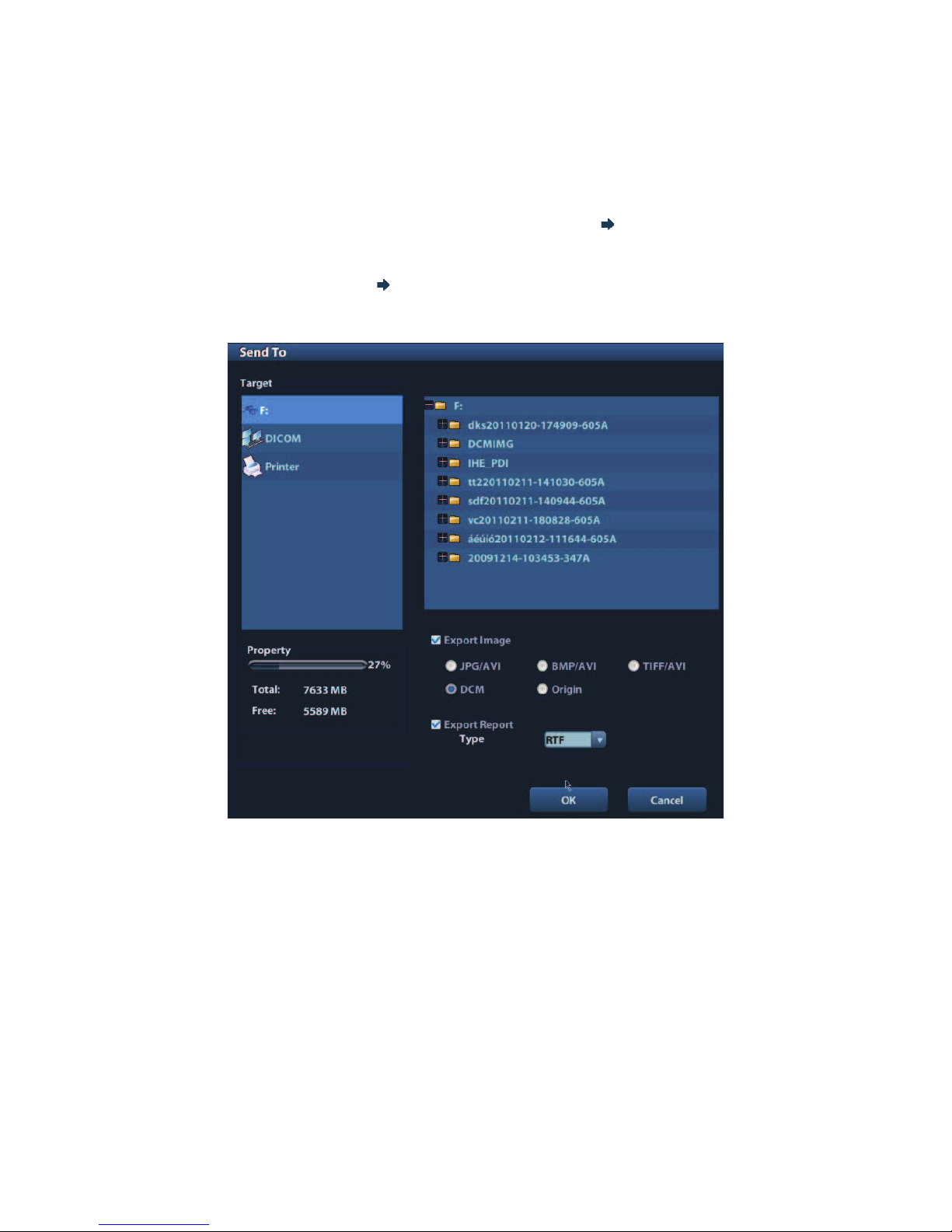
9-8 Data Management
Option of Demo
You can choose whether to repeat the demonstration or exit after a demonstration is
completed.
9.2.10 Sending Image File
On the image screen, select a stored image thumbnail, click
(Send To) on the right
corner of the image, the image can be sent to the external device, DVD recorder, DICOM
storage server, DICOM print server, system connected printer and etc.
In the iStation screen, click
; or, in Review screen, click [Send To] to send the selected
image to the external devices.
See the figure below.
z
For external memory devices (e.g. USB memory devices and DVD):
a) PC format transfer: JPG/ AVI, BMP/ AVI, TIFF/ AVI. Where a single-frame image
is exported as JPG, TIFF or BMP, and the cine file exported as AVI.
b) DCM format transfer: DCM( including single-frame DCM and multi-frame DCM).
c) You can also select to export report in RTF format.
z For DICOM Storage or Print server, select the DICOM Storage or Print server.
z For a video printer, send images to the video printer connected with the system. For
a graph/ text printer, send the images to the default graph/ text printer.
9.3 Report Management
Report storage:
The exam reports are stored under the directory of the exam of the animal.
Page 99

Data Management 9-9
Importing, exporting and sending a report
In the iStation screen, select animal data, click
(Restore) or (Backup) to import or
export animal information, images and reports from or to an external memory device. See
the following figure:
In the iStation screen, click ; or, in Review screen, click [Send To] to send animal data
to an external memory device, you can choose if reports are exported with images. See
the figure below.
To export the report:
(1) Check !Export Report" on the screen.
(2) Click [OK] to confirm.
You can select paper size for the report in the path: [Setup] ĺ [Print Preset]
Page 100

9-10 Data Management
Printing report
Use a connected graph/text printer to print a report. Please refer to !11.7 Print Preset" for
details about default report printer setting.
For details on report relevant operations, please refer to [Advanced Volume].
9.4 Data Management (iStation)
The animal data include basic animal information, exam information, image files and reports.
You can search, view, backup, send, restore or delete animal data in iStation.
To Enter iStation
z Press <iStation> key on the control panel; or
z Click [iStation] in the Animal Info screen; or
z Click [iStation] in the Review screen.
The iStation screen is shown as follows:
Viewing Animal Information
Data Source
Select the data source of animal data, the system animal database is default.
Record List
Display animal information, exam mode, number of images and cines, exam state,
backed up or not.
New Exam:
After you select an animal data or exam in the iStation screen, click the [New Exam] to
enter the Animal Info screen, where you can select a new exam mode and click [OK] to
begin a new exam.
 Loading...