

Eicher EE483TC, EE483TCI Operation And Maintenance Manual

Pub. No : M190456 : 01
Nov 2012
OPERATION AND MAINTENANCE MANUAL
EE483TCI Power Generation EngineEE483TC &
1
CONTENTS
Section
Details
Page No
Part I
Introduction-Operation & Maintenance
Manual
2
Part II Eicher Engine - General Information 3
Part III
Engine Familiarization
3 General Information 4
3.1- Engine Identification 4
3.2- Engine Nomenclature 5
3.3- Engine orientation and Parts
Illustration
6 to 8
3.4- Technical Specification- Engine 9 to 10
3.5- Engine Systems and Function 11
3.5.1- Air Intake and Exhaust System 11 to 13
3.5.2- Lubrication System 14 to 17
3.5.3- Fuel System 17 to 19
3.5.4- Cooling System 20 to 21
Part IV Engine Electrical System 22 to 23
Part V Safety Guidelines 24 to 25
Part VI Recommended Routine Checks By user 26 to 28
Part VII Engine Inspection and Maintenance 29 to 38
Part VIII Trouble Shooting Guidelines 39 to 47

2
PART I-INTRODUCTION - OPERATION & MAINTENANCE MANUAL
We are glad to introduce us as VE Commercial Vehicles Ltd (VECV), manufactures of EICHER EE483TC and
EE483TCI Power Generation Engine owned by you. VECV is committed to being the leader in customer
satisfaction in India and emerging markets. We put our best efforts to maintain global quality levels by
understanding and fulfilling customer needs.
This manual presented to you gives a comprehensive understanding on Construction, operation and
Maintenance aspects of Engine for the intended application.
These Engines meets current prevailing emission norms.
Due care has been taken in preparing this manual. However due to Continuous improvements product
specifications and illustrations are likely to undergo change without any prior notice.
For any further information, please write to:
PRODUCT SUPPORT
NON AUTOMOTIVE ENGINES
VE Commercial Vehicles Limited
(A Volvo Group and Eicher Motors Joint Venture)
102, Industrial Area No. 1 Pithampur 454775 Dist. Dhar (M.P.) India
Phone: (07292) 402633
Fax: (07292) 402611
PUBLICATION NO: M190456:00 REVISION NO: 01
PUBLICATION MONTH: NOVEMBER’2012 REVISION DATE: 01/11/2012

3
PART II: EICHER ENGINE GENERAL INFORMATION:
Eicher EE483TC Engines manufactured by VE Commercial Vehicles Ltd (VECV) are direct injection, four
Strokes, Water cooled, and Turbo charged Diesel Engines designed to suit Power Generation application.
Eicher EE483TCI Engines manufactured by VE Commercial Vehicles Ltd (VECV) are direct injection, four
Strokes, Water cooled, Turbo charged, Intercooled Diesel Engines designed to suit Power Generation
application.
The engines are eco-friendly, reliable and fuel efficient meets prevailing statutory emission standards.
While we, at manufacturing and testing have taken due care to ensure trouble free performance, as an
engine owner and user, proper up keep of engine, use of genuine parts, use of Genuine oil and Lubricants,
use of Genuine Coolant and adherence to scheduled and preventive maintenance shall derive the best out of
your engine resulting in Value for investment.
4
PART III: ENGINE FAMILIARIZATION
3. GENERAL
This part provides details about engine identification, engine Sl No nomenclature, Orientation, technical
specifications and various Systems of engine.
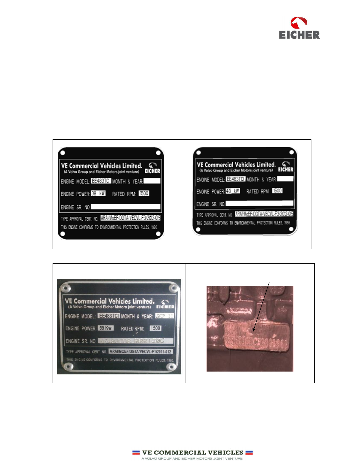
3.1 ENGINE IDENTIFICATION.
Engine is identified with the engine nameplate fitted on flywheel housing on left hand side of the engine
when viewed from front. Engine name plate contains the information as shown in the figure 1, 2 and 3.
Engine Sl No is also punched on the Cylinder block as shown in the figure 4.
Fig-
1- EE483TC-38 Kw
Fig 2 – EE483TC-48 Kw
Fig-3-EE483TCI-59 Kw
Engine Sl No Punched on Cylinder Block
Fig-4
5
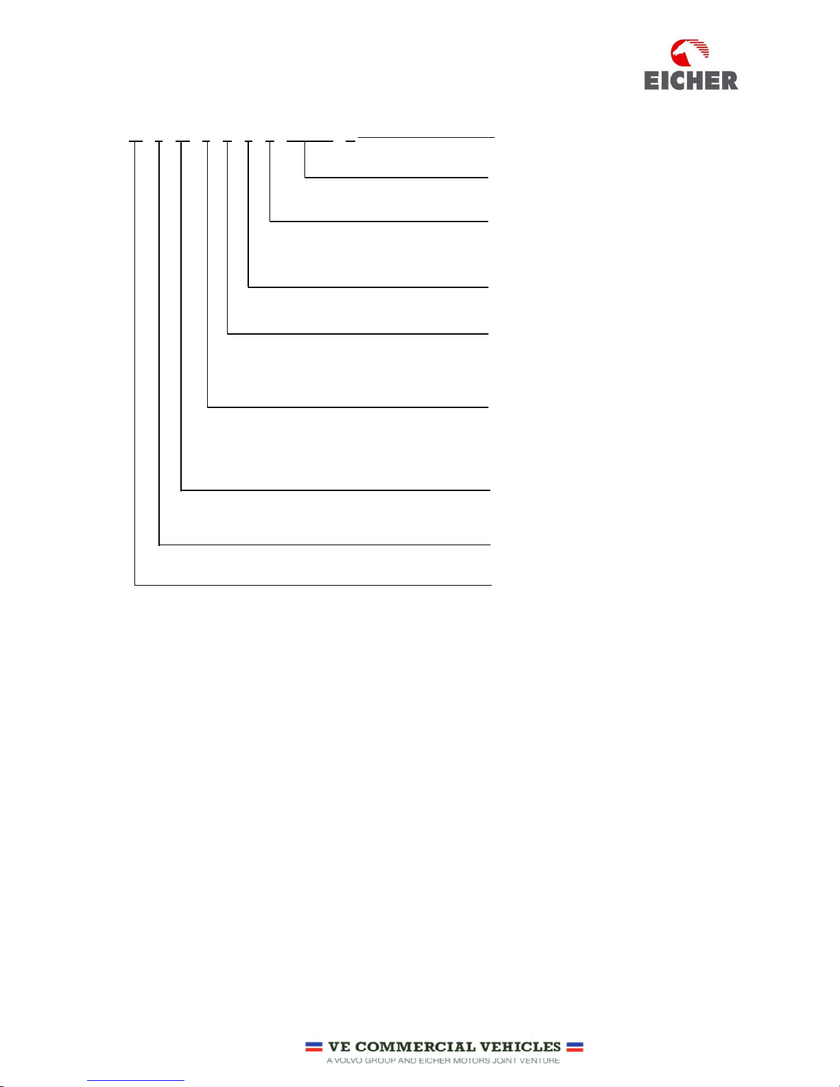
3.2 ENGINE NOMENCLATURE:
EE 4 83 C D B A 100000 G
Running Serial number
Month of production (A to M), A= Jan
& M = Dec.
Note: “I” is omitted
Year of production (A to W), A= 2010
W=2028.
Note: “I” is omitted
Type of fuel used
(D=Diesel)
Version: N=NA (Naturally aspirated)
C= TCI (Turbo Charged intercooled)
T=TC (Turbo Charged)
Swept Volume per cylinder
83=0.83 Litres
No. of Cylinders (4 or 6)
EICHER
G- Identification for Power
Generation Engine
6
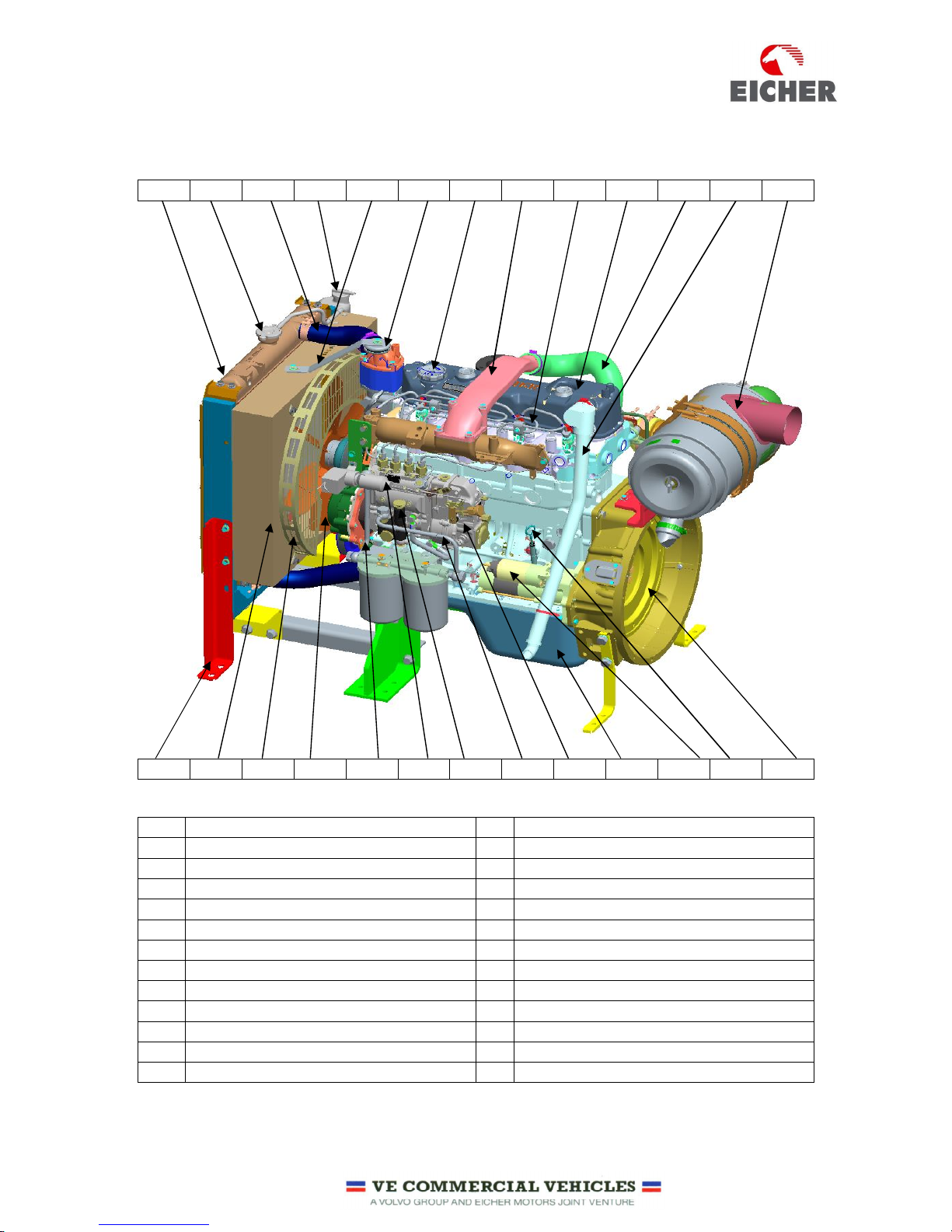
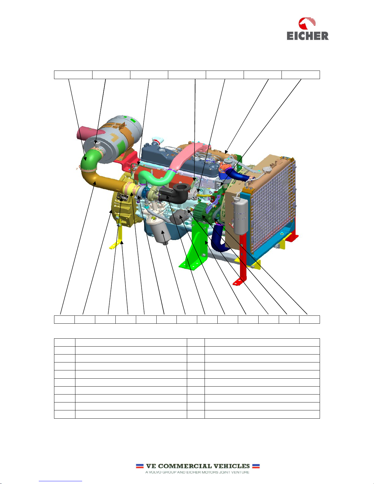
3.3 ENGINE ORIENTATION AND PARTS ILLUSTRATION (EE483TC -TURBO CHARGED ENGINE):
1 2 3 4 5 6 7 8 9 10 11 12 13
14 15 16 17 18 19 20 21 22 23 24 25 26
1 Radiator
14
Strip-Support radiator
2
Radiator Cap
15
Shroud Radiator
3
Hose
- Radiator In
16
Guard Fan Radiator
4
Tank Condenser
17
Fan Cooling Radiator
5
Bracket
– Radiator Support
18
Pipe-
Fuel filter to Fuel injection pump
6
Cushion
-
Radiator Support Bracket
19
Stop Solenoid
7
Cap Oil Filler
20
Feed pump
8
Pipe-
Turbo to Intake Manifold
21
Pipe fuel
- Feed Pump to fuel filter
9
High Pressure Pipe
22
Fuel injection Pump
10
Rocker Cover
23
Oil Sump
11
Hose
- Turbo out
24
Starter Motor
12
Hose
Breather
25
Dip
Stick 13 Air cleaner Assembly
26
Flywheel
7
ENGINE ORIENTATION AND PARTS ILLUSTRATION (EE483TC -TURBO CHARGED ENGINE) CONTD:
27 28 29 30 31 32 33
34 35 36 37 38 39 40 41 42 43 44 45 46
27 Hose
– Air cleaner
37
Pedestal
- Rear
for Transportation
28
Switch
-
Choke Air Cleaner
38
Hose
- turbo charger in
29
Pipe-
Lubrication Turbocharger
39
Turbo charger
30
Manifold
- Exhaust
40
Filter Oil
– Main
31
Cooler
- Oil 41 Bend Exhaust
32
Manifold
- Intake
42
Filter
- By Pass
33
Switch Cum
Sensor
- Water Temperature
43
Pedestal
– Front
34
Pipe-
Air Cleaner to Turbo
44
Sensor
-
oil Pressure
35
Housing flywheel
45
Alternator
- Battery charging
36
Engine Identification plate
46
V Belt
- Engine/Alternator/Water
pump
8
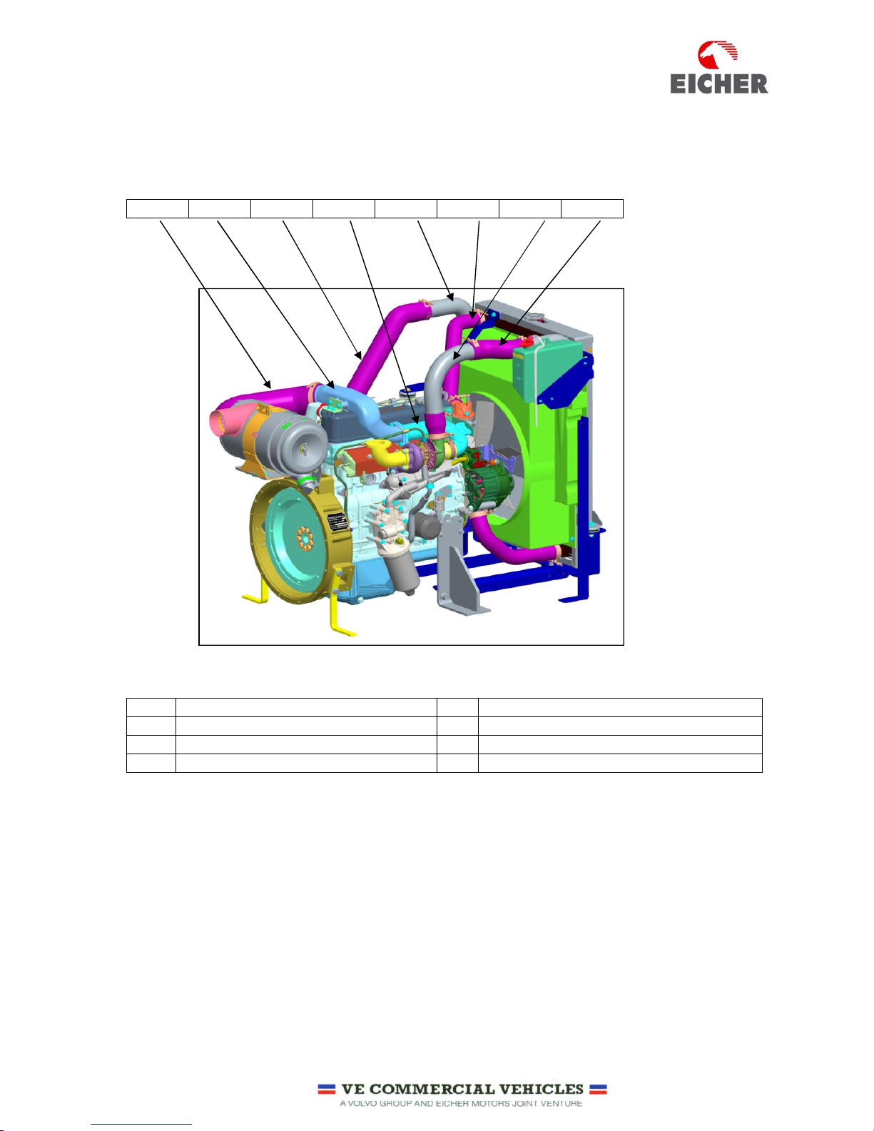
ENGINE ORIENTATION AND PARTS ILLUSTRATION (EE483TCI -TURBO CHARGED INTERCOOLED ENGINE):
1 2 3 4 5 6 7 8
1 Hose
-
Air Filter to Pipe TC in B
5
Intercooler Assy
2
Pipe TC in B
6
Hose
– Thermostat to Radiator
3
Hose
- Intercooler Outlet
7
Pipe-Turbo
Charger to Intercooler inlet
4
Pipe TC in A
8
Hose
-
Pipe Intercooler inlet to Intercooler in
9
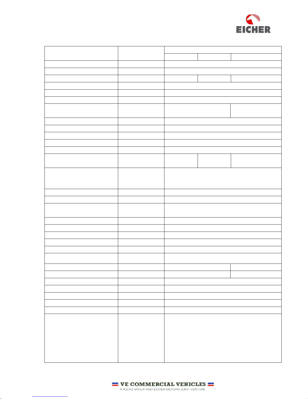
3.4 ENGINE TECHNICAL SPECIFICATIONS:
Parameters Unit
Details
40 Kva 50 Kva 62.5 Kva
Engine Manufacturer Name VE Commercial Vehicles Ltd
Engine Make Make EICHER
Engine Model Model EE483TC EE483TC EE483TCI
Emission Compliance Standard CPCB1 – As Per GSR 448 (E) 12.07.2004
No of Cylinders Nos. 4
Engine Configuration Configuration Inline / 4 Stroke
Engine Aspiration Type Turbo Charged
Turbo Charged
Inter cooled
Engine Fuel Type High Speed Diesel
Combustion Chamber Type Type Direct injection
Cylinder Bore X Stroke Mm 100 X 105
Engine Displacement Litres 3.3
Compression ratio Ratio 17:1 ± 0.5 mm
Engine Rated Output Kw ( HP) @ RPM
38 (52) @
1500
48 (65) @
1500 RPM
59 (80) @ 1500
Standard Operating
Conditions
Ambient /
Relative Humidity
/ Altitude
25°C / 40 % / 1000 mbar
Engine Deration Applicability Above 4000 feet
Rating Standard Standard IS10000
Overload Permissibility
10 % over load Permissible for 1 Hour in Every
12 Hours of Operation
Governing Standard Standard BS5514 / IS 10000
Governing Class Class A 1
Engine Low Idling Speed RPM 700 ± 50
Engine Fly Up Speed RPM 1560 ± 10
Engine Firing order Sequence 1-3-4-2
Direction of Rotation Direction Anti Clock wise when viewed from Flywheel End
Flywheel Standard SAE J 620 SAE 10 SAE 11.5
Flywheel Housing Standard SAE J 620 SAE 3 SAE 2
Lubrication Method Method Oil Pump Forced feed system
Oil Pump Type Gear Type
Oil Filter-Main Type / Nos. Paper Type / Single
Oil Filter-By Pass Type Spin on Type Paper
Oil Cooler Type Shell Type
Engine Lubricating Oil
Specification /
Grade /
Recommendation
API CH4-SAE 15W40 / EICHER Premium Diesel
Engine Oil
10
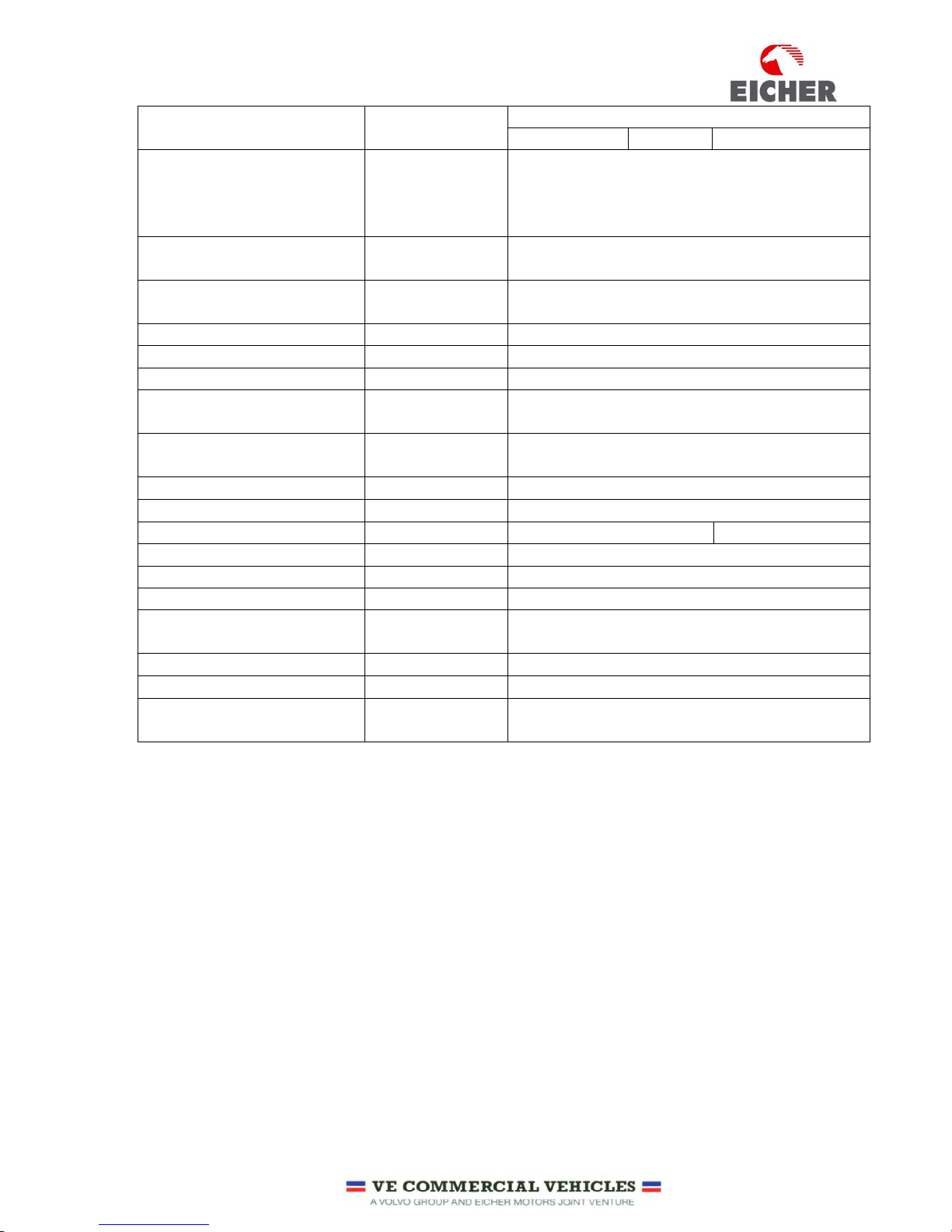
Parameters Unit
Details
40 Kva 50 Kva 62.5 Kva
Lubricating Oil Consumption
% of Fuel
Consumption
< 0.15 %
Minimum Lubricating Oil
Pressure @ Low Idle
Bar 1.5
Max Lubricating Oil Pressure
@ Fly up Speed
Bar 5.5
Fuel Injection Pump Make/Type Bosch / Inline
Fuel Filter Type / Nos. Cartridge type / 2 Nos.
Cooling Method Method Liquid Cooling / Forced Circulation
Water Pump Type
Centrifugal
Coolant
Specification /
Recommendation
JIS-K-2234-94 / EICHER GENUINE RADIATOR
COOLANT
Engine Cooling Fan Type Pusher
Electrical System V 12
Starter Motor Make / V / Kw Bosch / 12 / 1.9 Kw Bosch / 12 / 3.2
Battery Charging Alternator Make / V / Amps Bosch / 14 / 49
Shut off Solenoid Type Energise to Stop
Switch – Low Oil Pressure Applicability Yes
Switch – High Coolant
Temperature
Applicability Yes
Switch- Air Cleaner Choke Applicability Yes
Sensor-Water temperature Applicability Yes (Integral Design with Switch)
Sensor-Lubricating Oil
Pressure
Applicability Yes
11
3.5 ENGINE SYSTEMS AND ITS FUNCTION:
As we all know, Diesel engine is a prime mover developing useful power. Air and fuel is required to produce
power. Lubrication is necessary for the moving parts of the engine. Continuous cooling is required to
dissipate heat generated during combustion. Electrical system is required for engine starting, battery
charging and sensing of critical engine operating parameters.
The construction of Eicher diesel engine is divided in to five parts as below.
1 Air intake and Exhaust System
2 Lubrication System
3 Fuel System
4 Cooling System
5 Electrical System
The below section provides details of function, key components and working principle of respective system
to understand better about Engine aspects.
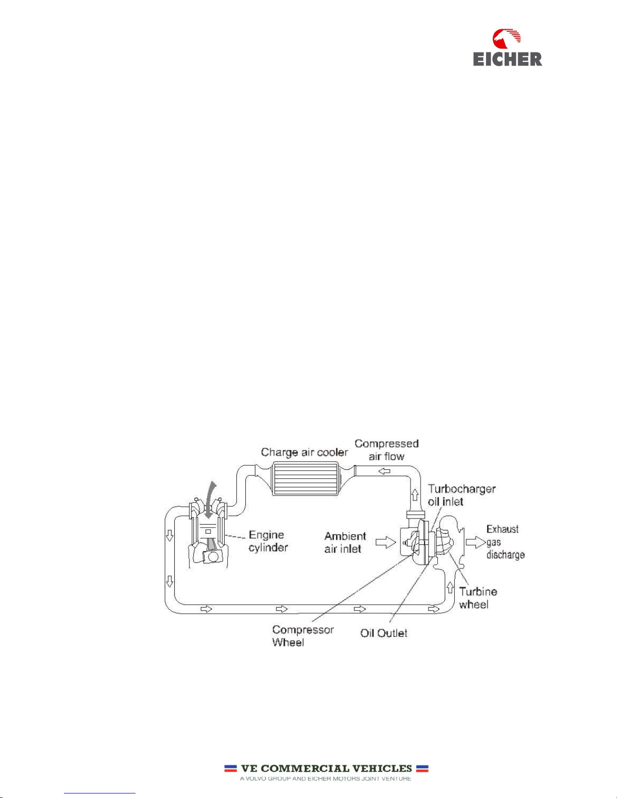
3.5.1 AIR INTAKE AND EXHAUST SYSTEM
TURBO CHARGED INTERCOOLED ENGINES:
The function of air system is to supply clean, cool and sufficient quantity air required for proper combustion
of the fuel which results in designed power output of the engine and maintains emissions as per statutory
norms.
Air intake system facilitates cleaning of air, induction of air, compression of air through turbocharger and
cooling by intercooler.
Air is sucked from atmosphere and passed through the Air filter to restrict dust and other foreign particles
from entering into air intake system. Clean air is then induced and compressed by the turbocharger
compressor wheel. Turbocharger increases the temperature of the air. This high temperature air is then
passed through an intercooler which decreases its temperature. As air inducted cools down its density is
12
further increased. Due to more air with desired density of air inducted into the engine there will be complete
combustion resulting in:
• Increase in power and torque without increasing the size of the engine.
• Improves fuel economy.
• Reduce engine noise.
• More complete combustion resulting in cleaner emission
TURBO CHARGED ENGINES:
In turbo charged engines, intercooler will not be present. The Compressed air from turbo charger will be
directly inducted into the combustion chamber. The combustion parameters will be designed to suit the air
temperature inducted in to the combustion chamber and accordingly desired quantity of fuel will be
supplied to ensure better fuel economy and complete combustion to achieve emission characteristics.
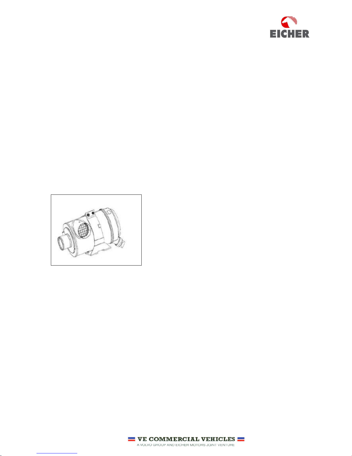
AIR FILTER:
Air filter is fitted on the Suction Side. It is paper cartridge dry type air filter comprising of inner and outer
element. Air filter prevents dust and other foreign particles entering into the air inlet system. The restriction
Indicator fitted on the filter gives indication when air filter gets clogged.
Do not run the engine with clogged air filter. Clogged air filter reduces
power output, fuel efficiency; higher exhaust emissions and affects
engine performance.
Air filter outer element shall be cleaned whenever the restriction
indicator gives indication. There are limitations for cleaning as
frequent cleaning affects air filter filtration efficiency. Follow the
recommendation for cleaning procedures and permissible number of
cleaning.
The inner element should not be cleaned and it should be replaced.
Never run the engine without air filter. Running without air filter will cause foreign object entering into air
system and results in turbocharger and engine failures.
TURBO CHARGER:
The exhaust gases discharged from the combustion chamber are driven out through the exhaust manifold
into the turbo charger and accelerated in the turbine housing to turn the turbine wheel driving away the
Exhaust gases through the muffler to the atmosphere.
Simultaneously, the compressor wheel mounted on the same shaft spins at the designed speeds. The
centrifugal action draws air from air cleaner and builds up the boost pressure in the intake system.
13
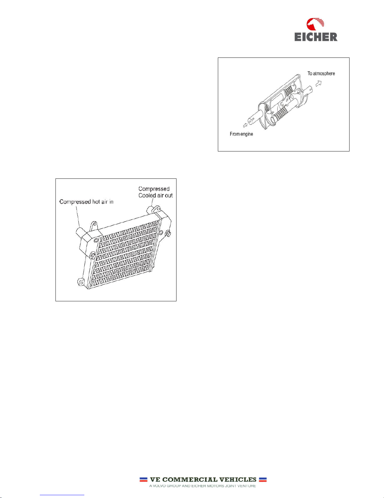
SILENCER:
Silencer is used to reduce the noise of exhaust gas /
Smoke.
The exhaust gas is sent through a number of small holes
provided inside the silencer which results in sudden
expansion of exhaust gases.
This results in reduction in exhaust noise.
For specific applications like Power Generation residential
mufflers are used to achieve reduction in noise levels.
INTER COOLER (APPLICABLE FOR TURBO CHARGED INTERCOOLED ENGINES):
Compressed hot air from turbocharger flows through the
tubes of intercooler.
Pusher type radiator cooling fan charges Cold air through the
intercooler fins carries away the heat from compressed hot air
flowing through the intercooler tubes thereby reducing the
temperature of air to the designed temperature levels. This
compressed cold air rushes in to the combustion chamber.
14
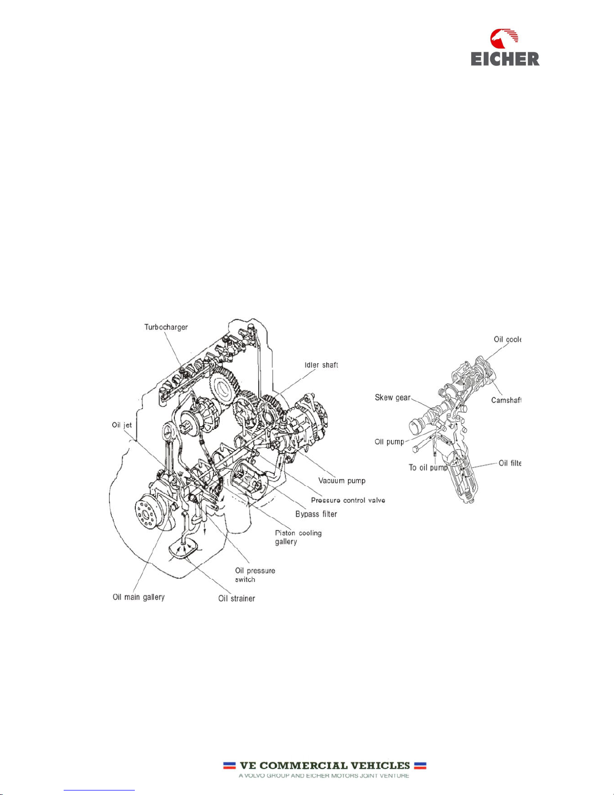
3.5.2 LUBRICATION SYSTEM:
The engine has a forced lubrication system. The main functions of the Lubrication systems are as follows:
• Lubricates moving engine parts by forming a thin film of oil between components and prevents
metal to metal contact
• This oil film is capable of absorbing shocks in Con-rod Bearings and Gear train
• Flowing oil absorbs heat and cools engine parts
• Oil also collects carbon & metal particles formed during engine operation and flows it to the oil pan
• Oil neutralizes the acids and alkali produced during engine operation & prevents corrosion
• Seals compression by forming a thin oil film on cylinder liner walls
ENGINE OIL FLOW PATH:
 Loading...