

MR2535L
TRANSIENT SUPPRESSORS
VBR : 20 Volts
Io : 35 Amperes
FEATURES :
* Avalanche Voltage 24 to 32 Volts
MAXIMUM RATINGS AND ELECTRICAL CHARACTERISTICS
Rating at 25
°
C ambient temperature unless otherwise specified.
Single phase, half wave, 60 Hz, resistive or inductive load.
For capacitive load, derate current by 20%.
* High Power capability
* Increased Capacity by Parallel Operation
MECHANICAL DATA :
* Case : Molded plastic
* Epoxy : UL94V-O rate flame retardant
* Lead : Axial lead solderable per MIL-STD-202,
Method 208 guaranteed
* Polarity : Cathode polarity band
* Mounting position : Any
* Weight : 2.69 grams
AUTOMOTIVE
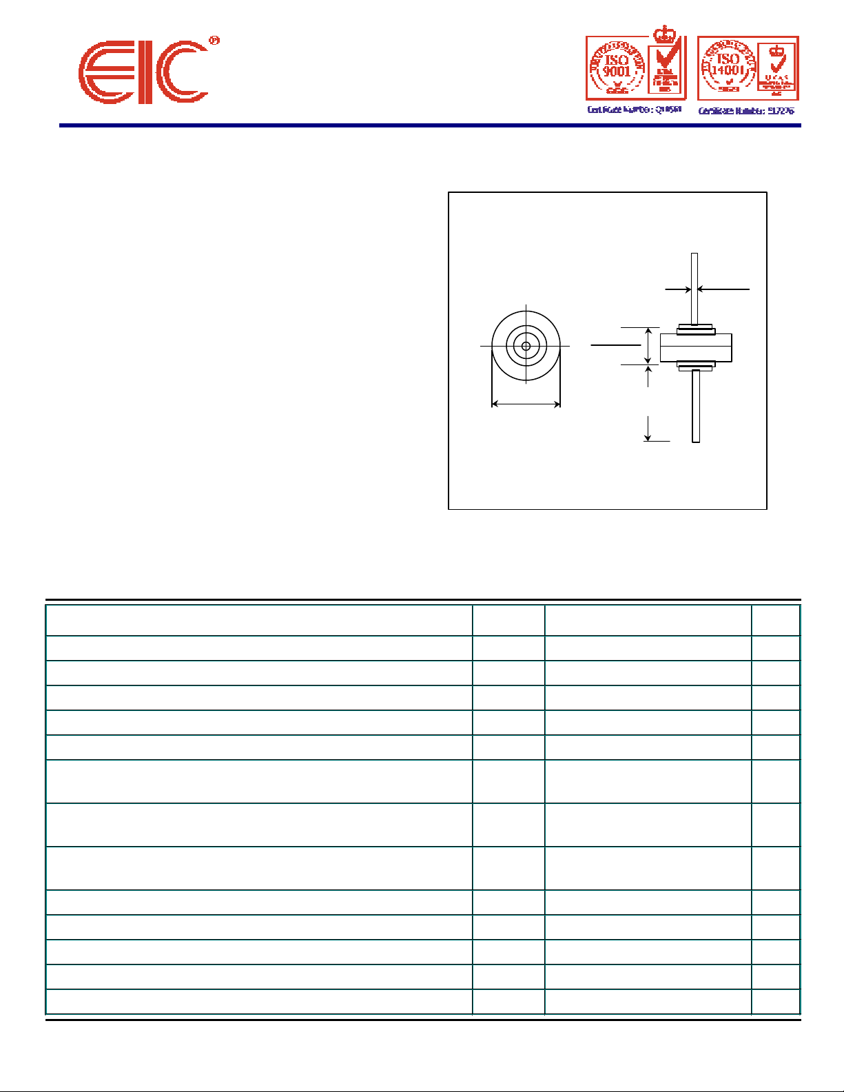
MR - L
0.053 (1.35)
0.050 (1.27)
0.246 (6.25)
0.234 (5.94)
0.342 (8.69)
0.332 (8.43)
Dimensions in inches and ( millimeter )
1.00 (25.4)
MIN.
RATING
Maximum DC Peak Repetitive Reverse Voltage VRRM 20 Volts
Maximum Working Peak Reverse Voltage VRWM 20 Volts
Maximum DC Blocking Voltage VR 20 Volts
Maximum Breakdown Voltage ( IR = 100 mA, Tc = 25°C ) (1) VBR(max) 32 Volts
Minimum Breakdown Voltage ( IR = 100 mA, Tc = 25°C ) (1) VBR(min) 24 Volts
Average Rectified Forward Current IF(AV) 35 Amps.
( Single Phase, Resistive Load, 60 Hz, Tc = 150 °C )
Maximum Repetitive Peak Reverse Surge Current IRSM 110 Amps.
( Time Constant = 10 ms, Duty Cycle ≤ 1%, Tc = 25 °C )
Maximum Non-Repetitive Peak Surge Current IFSM 600 Amps.
Surge Supplied at Rated Load Conditions, Halfwave, Single Phase
Maximum Instantaneous Forward Voltage (IF = 100 Amps. Tc = 25 °C) (1) VF 1.1 Volts.
Maximum Reverse Current ( V R = 20 Volts, Tc = 25 °C ) IR 200 nA
Typical Thermal Resistance Junction to Case RθJC 0.8 °C/W
Junction Temperature Range TJ - 65 to + 175 °C
Storage Temperature Range TSTG - 65 to + 175 °C
SYMBOL VALUE UNIT
Note : (1) Pulse Test : Pulse Width ≤ 300µs, Duty Cycle ≤ 2%.
UPDATE : MAY 24, 1999
 Loading...