

LCE SERIES
TRANSIENT VOLTAGE
SUPPRESSOR
PPK : 1500 Watts
FEATURES :
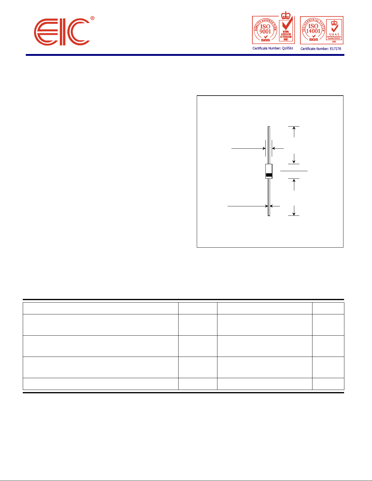
MECHANICAL DATA
MAXIMUM RATINGS
Note :
UPDATE : MARCH 29, 2002
VBR : 6.5 - 90 Volts
* 1500W Peak Pulse Surge reverse
capability on 10/1000µs waveform
* Excellent clamping capability
* Low incremental surge resistance
* Fast response time : typically less than 5.0 ns
from 0 volts to BV
* Case : DO-201AD Molded plastic
* Epoxy : UL94V-O rate flame retardant
* Lead : Axial lead solderable per MIL-STD-202,
method 208 guaranteed
* Polarity : Color band denotes positive end on the
Transorb (cathode)
* Mounting position : Any
* Weight : 0.93 gram
LOW CAPACITANCE
DO-201
0.21 (5.33)
0.19 (4.83)
0.042 (1.07)
0.038 (0.97)
Dimensions in inches and (millimeters)
1.00 (25.4)
MIN.
0.375 (9.53)
0.285 (7.24)
1.00 (25.4)
MIN.
Rating at 25 °C ambient temperature unless otherwise specified.
Rating Symbol Value Unit
Peak Pulse Power Dissipation on 10/1000µs
waveform (Note 1, Figure 1)
Steady State Power Dissipation at TL = 75 °C
Lead Lengths 0.375", (9.5mm) (Note 2)
Peak Forward Surge Current on 10/1000 µs
Waveform (Fig. 3, Note 1)
Operating and Storage Temperature Range TJ, T
(1) Non-repetitive Current pulse, per Fig. 3 and derated above Ta = 25 °C per Fig. 2
(2) 8.3 ms single half sine-wave, duty cycle = 4 pulses per minutes maximum.
P
PPM
P
FSM
I
D
STG
Minimum 1500 Watts
5.0 Watts
See Table 1. Amps.
- 65 to + 175
°C

ELECTRICAL CHARACTERISTICS
Rating at 25
°
C ambient temperature unless otherwise specified
Reverse Maximum Maximum Maximum Maximum Working Max. Inverse Peak Inverse
Breakdown Voltage @ It Stand-off Reverse Clamping Reverse Junction Inverse Blocking Blocking
TYPE
NUMBER
LCE6.5
LCE6.5A
LCE7.0
LCE7.0A
LCE7.5
LCE7.5A
LCE8.0
LCE8.0A
LCE8.5
LCE8.5A
LCE9.0
LCE9.0A
LCE10
LCE10A
LCE11
LCE11A
LCE12
LCE12A
LCE13
LCE13A
LCE14
LCE14A
LCE15
LCE15A
LCE16
LCE16A
LCE17
LCE17A
LCE18
LCE18A
LCE20
LCE20A
LCE22
LCE22A
LCE24
LCE24A
LCE26
LCE26A
LCE28
LCE28A
LCE30
LCE30A
LCE33
LCE33A
LCE36
LCE36A
LCE40
LCE40A
LCE43
LCE43A
V
(V) It V
BR
Min. Max. (mA) (V) (µA) (V) (A) pF (V) mA (V)
7.22 8.82 10 6.5 1000 12.3 100 100 75 1.0 100
7.22 7.98 10 6.5 1000 11.2 100 100 75 1.0 100
7.78 9.51 10 7.0 500 13.3 100 100 75 1.0 100
7.78 8.60 10 7.0 500 12.0 100 100 75 1.0 100
8.33 10.2 10 7.5 250 14.3 100 100 75 1.0 100
8.33 9.21 10 7.5 250 12.9 100 100 75 1.0 100
8.89 10.9 10 8.0 100 15.0 100 100 75 1.0 100
8.89 9.83 10 8.0 100 13.6 100 100 75 1.0 100
9.44 11.5 1.0 8.5 50 15.9 94 100 75 1.0 100
9.44 10.4 1.0 8.5 50 14.4 100 100 75 1.0 100
10.0 12.2 1.0 9.0 10.0 16.9 89 100 75 1.0 100
10.0 11.1 1.0 9.0 10.0 15.4 97 100 75 1.0 100
11.1 13.6 1.0 10 5.0 18.8 80 100 75 1.0 100
11.1 12.3 1.0 10 5.0 17.0 88 100 75 1.0 100
12.2 14.9 1.0 11 5.0 20.1 74 100 75 1.0 100
12.2 13.5 1.0 11 5.0 18.2 82 100 75 1.0 100
13.3 16.3 1.0 12 5.0 22.0 68 100 75 1.0 100
13.3 14.7 1.0 12 5.0 19.9 75 100 75 1.0 100
14.4 17.6 1.0 13 5.0 23.8 63 100 75 1.0 100
14.4 15.9 1.0 13 5.0 21.5 70 100 75 1.0 100
15.6 19.1 1.0 14 5.0 25.8 58 100 75 1.0 100
15.6 17.2 1.0 14 5.0 23.2 65 100 75 1.0 100
16.7 20.4 1.0 15 5.0 26.9 56 100 75 1.0 100
16.7 18.5 1.0 15 5.0 24.4 61 100 75 1.0 100
17.8 21.8 1.0 16 5.0 28.8 52 100 75 1.0 100
17.8 19.7 1.0 16 5.0 26.0 57 100 75 1.0 100
18.9 23.1 1.0 17 5.0 30.5 49 100 75 1.0 100
18.9 20.9 1.0 17 5.0 27.6 54 100 75 1.0 100
20 24.4 1.0 18 5.0 32.2 46 100 75 1.0 100
20 22.1 1.0 18 5.0 29.2 51 100 75 1.0 100
22.2 27.1 1.0 20 5.0 35.8 42 100 75 1.0 100
22.2 24.5 1.0 20 5.0 32.4 46 100 75 1.0 100
24.4 29.8 1.0 22 5.0 39.4 38 100 75 1.0 100
24.4 26.9 1.0 22 5.0 35.5 42 100 75 1.0 100
26.7 32.6 1.0 24 5.0 43.0 35 100 75 1.0 100
26.7 29.5 1.0 24 5.0 38.9 39 100 75 1.0 100
28.9 35.3 1.0 26 5.0 46.6 32 100 75 1.0 100
28.9 31.9 1.0 26 5.0 42.1 36 100 75 1.0 100
31.1 38.0 1.0 28 5.0 50.1 30 100 75 1.0 100
31.1 34.4 1.0 28 5.0 45.5 33 100 75 1.0 100
33.3 40.7 1.0 30 5.0 53.5 28 100 75 1.0 100
33.3 36.8 1.0 30 5.0 48.4 31 100 75 1.0 100
36.7 44.9 1.0 33 5.0 59.0 25.4 100 75 1.0 100
36.7 40.6 1.0 33 5.0 53.3 28.1 100 75 1.0 100
40.0 48.9 1.0 36 5.0 64.3 23.3 100 75 1.0 100
40.0 44.2 1.0 36 5.0 58.1 25.8 100 75 1.0 100
44.4 54.3 1.0 40 5.0 71.4 21 100 75 1.0 100
44.4 49.1 1.0 40 5.0 64.5 23.3 100 75 1.0 100
47.8 58.4 1.0 43 5.0 76.7 19.5 100 150 1.0 200
47.8 52.8 1.0 43 5.0 69.4 21.6 100 150 1.0 200
Voltage Leakage Voltage Current Capacitance Blocking Current Voltage
@ V
RWM
I
R
RWM
@ I
V
RSM
RSM
I
RSM
@ 0 Volt Voltage @ V
V
WIB
WIB
I
IB
V
PIB

ELECTRICAL CHARACTERISTICS
Rating at 25
°
C ambient temperature unless otherwise specified
FIG.1 - PEAK PULSE POWER RATING CURVE
FIG.2 - PULSE DERATING CURVE
0.1
P
,PEAK POWER POWER
20
0257550100
125
150
175
Lead Lengths
Tf = 10µs
as defined by R.E.A.
Reverse Maximum Maximum Maximum Maximum Working Max. Inverse Peak Inverse
Breakdown Voltage @ It Stand-off Reverse Clamping Reverse Junction Inverse Blocking Blocking
TYPE
NUMBER
LCE45
LCE45A
LCE48
LCE48A
LCE51
LCE51A
LCE54
LCE54A
LCE58
LCE58A
LCE60
LCE60A
LCE64
LCE64A
LCE70
LCE70A
LCE75
LCE75A
LCE80
LCE80A
LCE90
LCE90A
V
(V) It V
BR
Min. Max. (mA) (V) (µA) (V) (A) pF (V) mA (V)
50.0 61.1 1.0 45 5.0 80.3 18.7 100 150 1.0 200
50.0 55.3 1.0 45 5.0 72.7 20.6 100 150 1.0 200
53.3 65.1 1.0 48 5.0 85.5 17.5 100 150 1.0 200
53.3 58.9 1.0 48 5.0 77.4 19.4 100 150 1.0 200
56.7 69.3 1.0 51 5.0 91.1 16.5 100 150 1.0 200
56.7 62.7 1.0 51 5.0 82.4 18.2 100 150 1.0 200
60.0 73.3 1.0 54 5.0 96.3 15.6 100 150 1.0 200
60.0 66.3 1.0 54 5.0 87.1 17.2 100 150 1.0 200
64.4 78.7 1.0 58 5.0 103 14.6 100 150 1.0 200
64.4 71.2 1.0 58 5.0 93.6 16 100 150 1.0 200
66.7 81.5 1.0 60 5.0 107 14 90 150 1.0 200
66.7 73.7 1.0 60 5.0 96.8 15.5 90 150 1.0 200
71.1 86.9 1.0 64 5.0 114 13.2 90 150 1.0 200
71.1 78.6 1.0 64 5.0 103 14.6 90 150 1.0 200
77.8 95.1 1.0 70 5.0 125 12 90 150 1.0 200
77.8 86.0 1.0 70 5.0 113 13.3 90 150 1.0 200
83.3 102 1.0 75 5.0 134 11.2 90 150 1.0 200
83.3 92.1 1.0 75 5.0 121 12.4 90 150 1.0 200
88.7 108 1.0 80 5.0 142 10.6 90 150 1.0 200
88.7 98.0 1.0 80 5.0 129 11.6 90 150 1.0 200
100 122 1.0 90 5.0 160 9.4 90 300 1.0 200
100 111 1.0 90 5.0 146 10.3 90 300 1.0 200
Voltage Leakage Voltage Current Capacitance Blocking Current Voltage
@ V
RWM
I
R
RWM
@ I
V
RSM
RSM
I
RSM
@ 0 Volt Voltage @ V
V
WIB
WIB
I
IB
V
PIB
100
(kW)
PPM
10
0.1µs 1.0µs 10µs 100µs
tp, PULSE WIDTH
RMS
PEAK PULSE CURRENT - % I
120
100
Average Power
1.0ms
10ms
100ms
80
60
40
PEAK POWER OR CURRENT
PEAK PULSE DERATING IN % OF
0
Peak Power
(single Pulse)
0.375"(9.5mm)
TL, LEAD TEMPERATURE (°C)
FIG.3 - PULSE WAVEFORM
TJ=25 °C
Peak Value
I
RMS
tp
0
10 2 3 4
Pulse Width (tp) is defined
as that point where the peak
current decays to 50%
of I
RSM
Half Value - I
10X1000 Waveform
RMS
2
T, TIME(ms)
 Loading...