

BZX85C Series
SILICON ZENER DIODES
VZ : 2.4 - 200 Volts
PD : 1.3 Watts
FEATURES :
* Complete Voltage Range 2.7 to 200 Volts
MECHANICAL DATA
* Case : DO-41 Molded plastic
* Epoxy : UL94V-O rate flame retardant
* Lead : Axial lead solderable per MIL-STD-202,
MAXIMUM RATINGS
Note :
(1) TL = Lead temperature at 3/8 " (9.5mm) from body
(2) Valid provided that leads are kept at ambient temperature at a distance of 10 mm from case.
0255075100
125
150
175
T
L,
LEAD TEMPERATURE (
°
C)
UPDATE : SEPTEMBER 9, 2000
1.5
Fig. 1 POWER TEMPERATURE DERATING CURVE
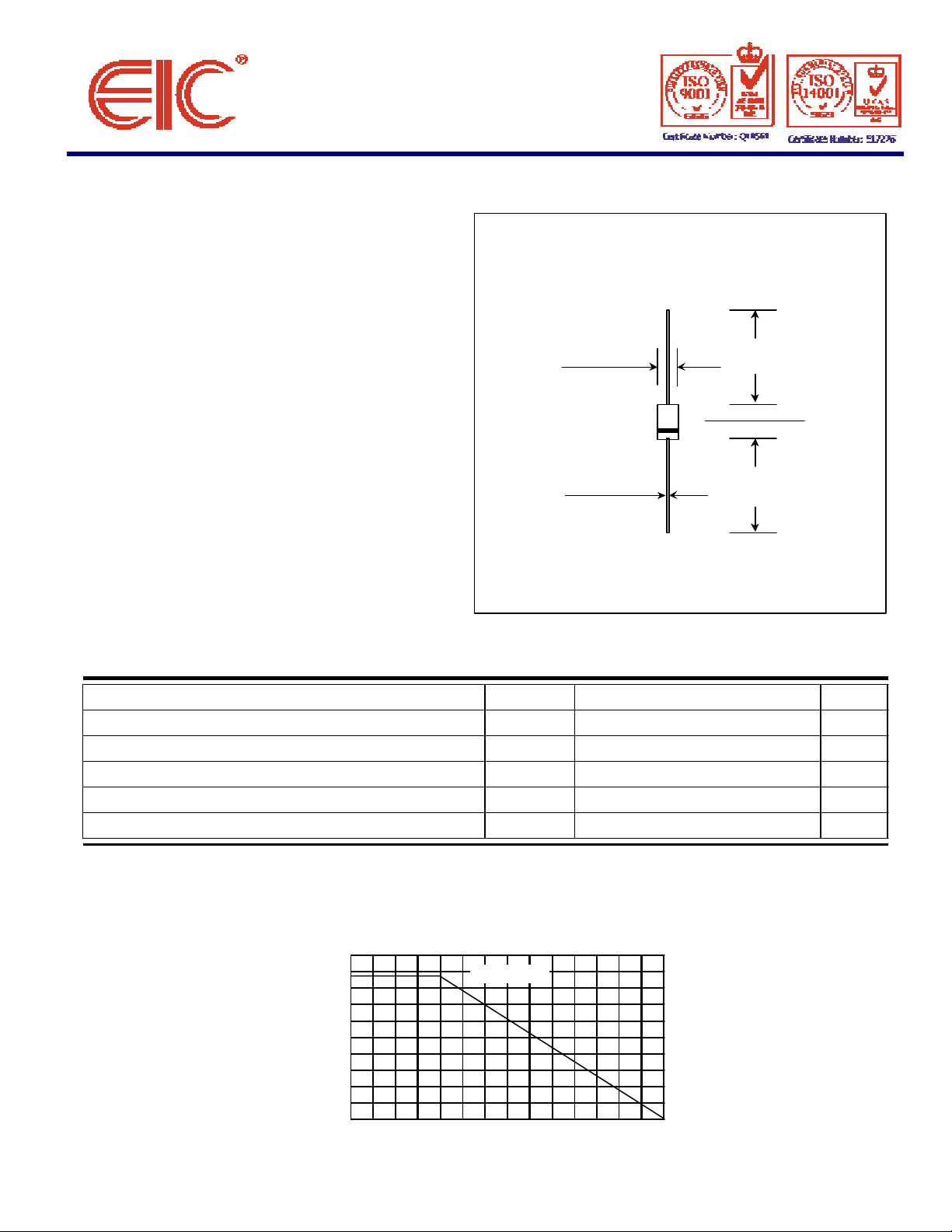
DO - 41
Dimensions in inches and ( millimeters )
0.166 (4.2)
* High peak reverse power dissipation
* High reliability
* Low leakage current
0.107 (2.7)
0.080 (2.0)
1.00 (25.4)
MIN.
0.205 (5.2)
0.034 (0.86)
0.028 (0.71)
method 208 guaranteed
* Polarity : Color band denotes cathode end
* Mounting position : Any
* Weight : 0.339 gram
Rating at 25 °C ambient temperature unless otherwise specified
Rating Symbol Value Unit
DC Power Dissipation at TL = 50 °C (Note1) P
Maximum Forward Voltage at IF = 200 mA V
Maximum Thermal Resistance Junction to Ambient Air (Note2)
Junction Temperature Range T
Storage Temperature Range Ts - 55 to + 175
D
F
RθJA
J
1.3 Watts
1.0 Volts
130 K / W
- 55 to + 175
1.00 (25.4)
MIN.
°
C
°
C
1.2
0.9
0.6
(WATTS)
0.3
PD, MAXIMUM DISSIPATION
L = 3/8" (9.5mm)
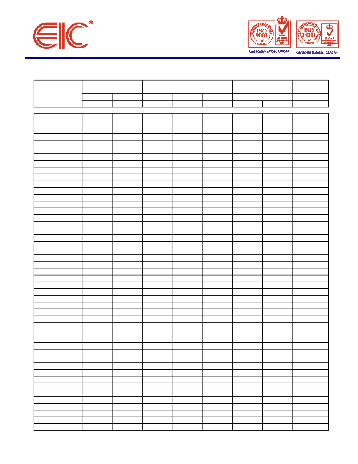
ELECTRICAL CHARACTERISTICS
Nominal Zener
Maximum Zener
Maximum Reverse
Maximum DC
VZ
@ IZTIZTZZT
@ IZTZZK
@ IZKIZKIR
@ VRIZM(V)
(mA)
(Ω)
(Ω)
(mA)
(µA)
(V)
(mA)
BZX85 C2V4
2.48020
400
1.0
150
1.0
410
BZX85 C2V7
2.78020
400
1.0
150
1.0
370
BZX85 C3V0
3.08020
400
1.0
100
1.0
340
BZX85 C3V3
3.38020
400
1.0401.0
320
BZX85 C3V6
3.67020
500
1.0201.0
290
BZX85 C3V9
3.96015
500
1.0101.0
280
BZX85 C4V3
4.35013
500
1.0
3.0
1.0
250
BZX85 C4V7
4.74513
500
1.0
3.0
1.0
215
BZX85 C5V6
5.6457.0
400
1.0
1.0
2.0
190
BZX85 C6V2
6.2354.0
300
1.0
1.0
3.0
170
BZX85 C7V5
7.5353.0
200
0.5504.5
140
BZX85 C8V2
8.2255.0
200
0.5506.2
130
BZX85 C9V1
9.1255.0
200
0.5506.8
120
BZX85 C10
10257.0
200
0.5507.5
105
BZX85 C11
11208.0
300
0.5508.2
97
BZX85 C12
12209.0
350
0.5
0.5
9.1
88
BZX85 C13
132010
400
0.5
0.51079
BZX85 C15
151515
500
0.5
0.51171
BZX85 C16
161515
500
0.5
0.51266
BZX85 C18
181520
500
0.5
0.51362
BZX85 C20
201024
600
0.5
0.51556
BZX85 C22
221025
600
0.5
0.51652
BZX85 C24
241025
600
0.5
0.51847
BZX85 C30
30
8.0301000
0.25
0.52236
BZX85 C33
33
8.0351000
0.25
0.52433
BZX85 C36
36
8.0401000
0.25
0.52730
BZX85 C39
39
6.0501000
0.25
0.53028
BZX85 C43
43
6.0501000
0.25
0.53326
BZX85 C47
47
4.0901500
0.25
0.53623
BZX85 C51
51
4.0
115
1500
0.25
0.53921
BZX85 C56
56
4.0
120
2000
0.25
0.54319
BZX85 C62
62
4.0
125
2000
0.25
0.54716
BZX85 C68
68
4.0
130
2000
0.25
0.55115
BZX85 C75
75
4.0
135
2000
0.25
0.55614
BZX85 C82
82
2.7
200
3000
0.25
0.56212
BZX85 C91
91
2.7
250
3000
0.25
0.56810
BZX85 C110
110
2.7
450
4000
0.25
0.5828.6
BZX85 C120
120
2.0
550
4500
0.25
0.5917.8
BZX85 C150
150
2.0
1000
6000
0.25
0.5
110
6.4
BZX85 C160
160
1.5
1100
6500
0.25
0.5
120
5.8
BZX85 C180
180
1.5
1200
7000
0.25
0.5
130
5.2
BZX85 C200
200
1.5
1500
8000
0.25
0.5
150
4.7
Note :
(1) The type number listed have a standard tolerance on the nominal zener voltage of
±
5.0%.
(2) " BZX " will be omitted in marking on the diode
Rating at = 25 °C ambient temperature unless otherwise specified
TYPE Voltage Impedance Leakage Current Zener Current
BZX85 C5V1 5.1 45 10 500 1.0 1.0 1.5 200
BZX85 C6V8 6.8 35 3.5 300 1.0 50 4.0 155
BZX85 C27 27 8.0 30 750 0.25 0.5 20 41
BZX85 C100 100 2.7 350 3000 0.25 0.5 75 9.4
BZX85 C130 130 2.0 700 5000 0.25 0.5 100 7.0
 Loading...