

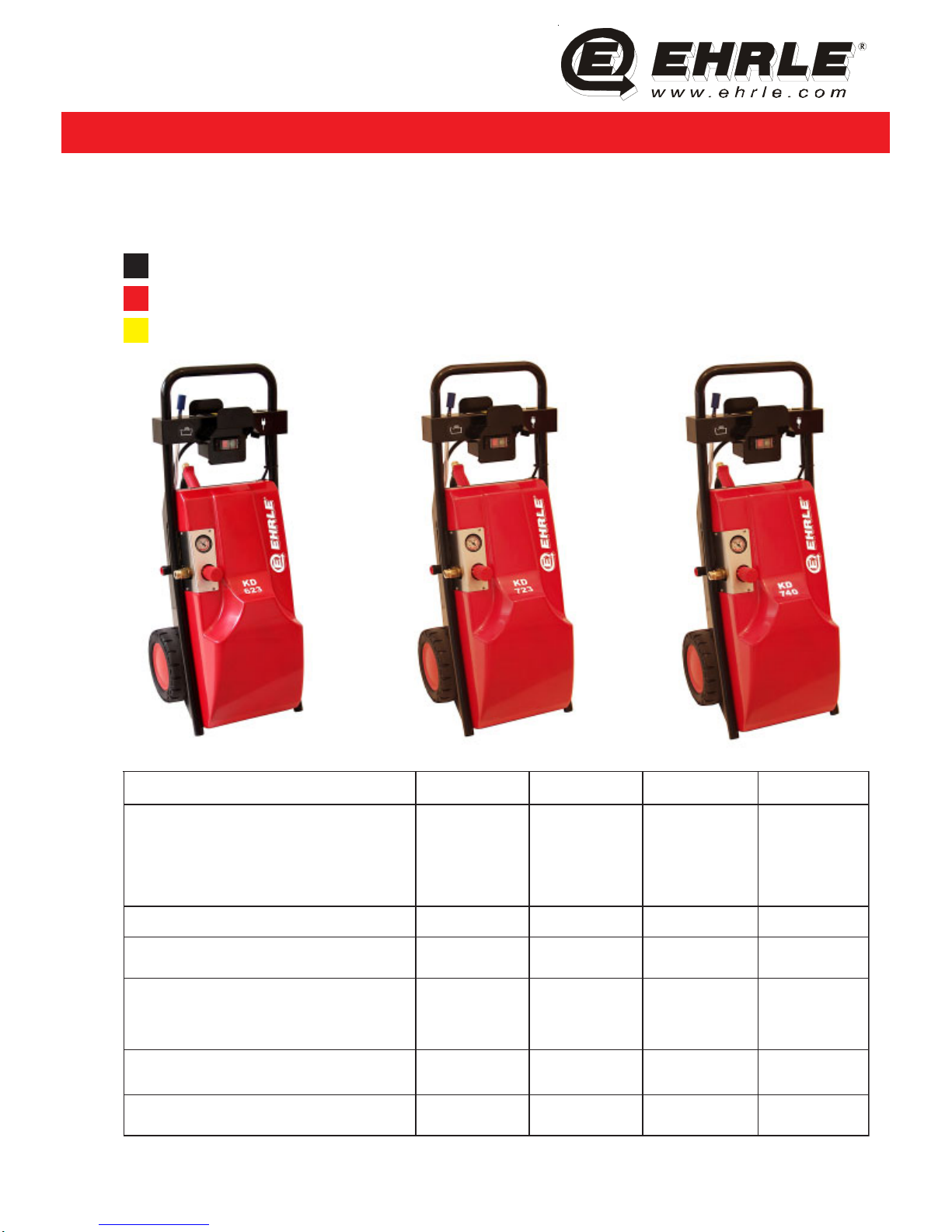
EHRLE KD 623, KD 723, KD 740 Operating Instruction
H
igh-Pressure-Cleaning-Systems
Operating Instruction
KD 623 - KD 723 - KD 740
1. Edition 01.06.2004 © EHRLE GmbH 2004. All rights reserved.
Ehrle GmbH - Siemens Street 9
D-89257 Illertissen Tel +49-7303-1600-0 Fax +49-7303-1600-60
Internet: www.ehrle.com - e-mail: info@ehrle.com
noitangiseD326DK327DK047DKtinU
:erusserpgnitarepO
:erusserpgnitarepO
:erusserp.xam
:elzzoNoL-iHedocroloC/elzzondradnatS
:elzzoNoburTedocroloC/elzzondradnatS
:levelnoitcus.xam
021-01
531
egnaro-540
egnaro-540
0,3
531-01
051
egnaro-540
egnaro-540
0,3
071-01
091
eulb-40
eulb-40
0,3
rab
rab
.rtm
:yticapacegrahcsiD 115,1121nim/l
:erutarepmeT
:erutarepmetyreviled.xam060606C°
:tupnilacirtcelE
:)ycneuqerf(egatloV
:daoldetcennoC
:ssalcnoitcetorP
)05(042-032CA
)0,21(-8,2
45PI
)05(042-032CA
)0,31(-0,3
45PI
)05(514-004CA3
)0,7(-8,4
45PI
)zH(V
)A(Wk
:snoisnemiD
thgieH/htdiW/thgneL693x273x069693x273x069693x273x069mm
:thgieW
:seirosseccatuohtiwthgiewteN248474gk
Warning! Observe Operating Instruction and Safety regulation for commissioning of the High Pressure
Cleaner. The machine apply the CE-Regulations.
made
in
Germany
H
igh-Pressure-Cleaning-Systems
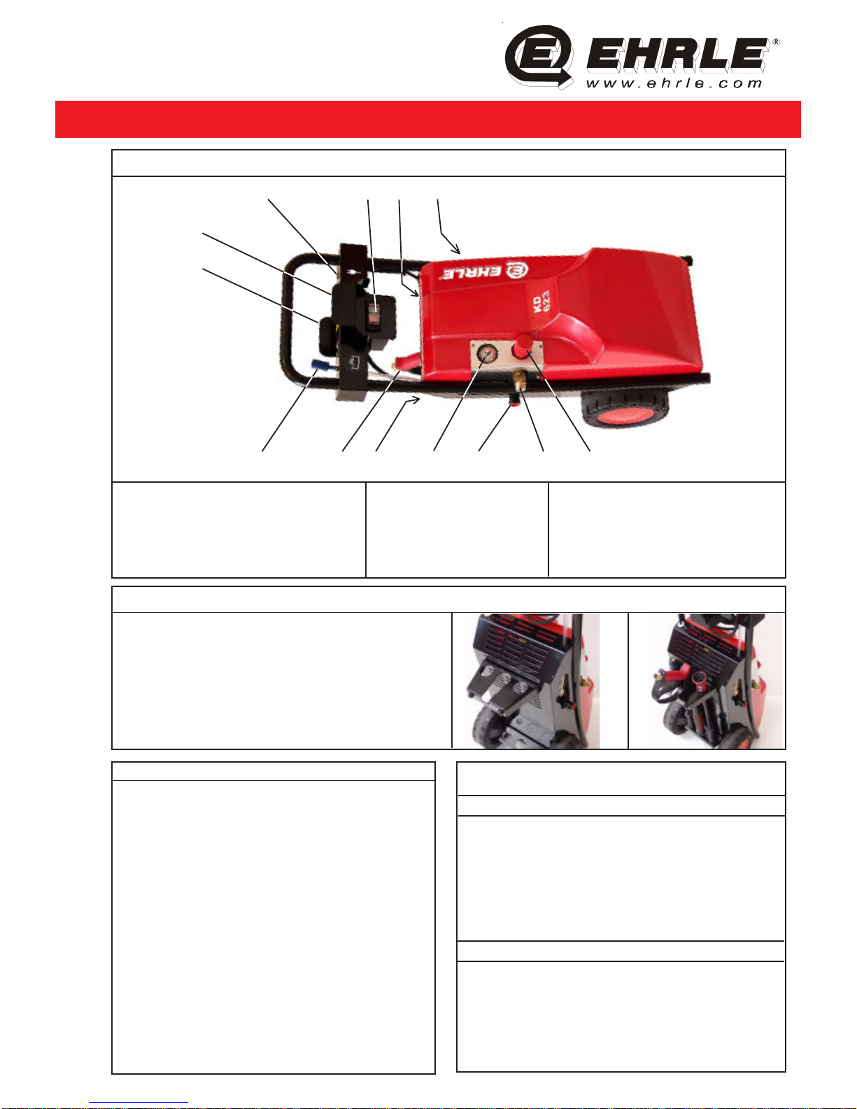
01 Electrical plug 06 Turbo-Nozzle 11 On / Off switch
02 Electrical cable mounting support 07 Pressure gauge 12 Hi-Lo-Nozzle
03 H.P. hose mounting support 08 Water inlet 13 Accessory mounting support
04 Chemical suction hose c/w. filter 09 H.P. outlet
05 H.P. trigger gun 10 Unloader valve
2. Commissioning
1. Unpack the H.P. Cleaner and check for complete
quantity and possible damages.
2. Assemble the accessory mounting support (13) with
washers and nuts, with the open side heading to the
bottom. (See Pic. 1)
3. Assemble the H.P. trigger gun (05), Hi-Lo-Nozzle (12) and
Turbo-Nozzle (06) into the accessory mounting support (13) .
(See Pic. 2)
1. Total View of the Machine and Description
3. Commissioning and Operating
1. Set On / Off switch (11) to position “0”.
2. Assemble the Hi-Lo-Nozzle (12) or Turbo-Nozzle
(06) to H.P. trigger gun (05).
3. Assemble H.P. hose to the H.P. trigger gun (05)
and H.P. outlet (09) to the H.P. Cleaner.
4. Assemble the water supply hose (min. 1/2” diam.)
to the water inlet (08) to the H.P. Cleaner.
5. Connect the AC power cable (01) to the AC power
oultet.
Attention: By using a AC power extension cable
please use a cross wire section of min. 2,5 mm².
6. Open the water supply shut off valve.
7. Set On / Off switch (11) to position “1”.
8. Adjust the Unloader valve (10) to the desired pressure .
9. By using cleaning detergent (chemicals): Put
chemical suction hose (04) in a cleaning detergent
Pic. 1 Pic. 2
02
01 110312
13
100908070604 05
container. Adjust Hi-Lo-Nozzle (12) to symbol chemical.
4. Decommissioning
1. Set On / Off switch (11) to position “0”. and remove
the AC power cable (01) from the AC power outlet.
2. Close the water supply shut off valve.
3. Pull the trigger gun (05) until the H.P. cleaner is
pressureless.
4. After finishing the work assemble the accessories
to the accessory mounting support.
5. Safety Regulation
Please read the Saftey regulation “Safety instruction
for ” H.P. Cleaner (included in the packing).
Operate the H.P. Cleaner only in horizontal position.
For resting periods longer than 10 minutes, please
switch off the H.P. Cleaner by On / Off switch (11).
 Loading...