


Ehrhorn Technological Operations Alpha 77 Service manual

INSTR UCTIO N AND TECHNICAL MANUAL
IDODEL PA-77 LI N E A R POWER AMP L I FIER
r«C#tt0£Q«$tA* tftft »x v-jK: ...
EHRHORN TECHNOLOGICAL OP ER AT ION S, INC .
BRO O KSVIL L E , FLORID A 33512
No vem ber 1 , 1972
TABLE OF CONTENTS
TABLE OF CONTENTS.......................................................................... i
STANDARD WARRANTY.......................................................................... i i
SECTION 1 - GENERAL DESCRIPTION AND SPECIFICATIONS. . 1
SECTION 2 - INSTALLATION ......................................................... 2
REAR PANEL INTERCONNECTIONS
SECTION 3 - OPERATION .................................................................. 5
CONTROL FUNCTIONS
TUNE-UP PROCEDURE ................................................ 6
FINAL OPERATIONAL ADJUSTMENTS, M ON I TOR ING B
PROTECTIVE DEVICES, OPERATING PRECAUTIONS 9
SECTION 4 - MAINTENANCE AND TROUBLESHOOTING..................12
SECTION 5 - THEORY OF OPERATION............................................14
SECTION 6 - IL LU STRATIO NS.........................................................19
TOP V IE W ....................................................................19
BOTTOM V IE W ............................................................. 20
REMOVAL OF POWER SU PPL Y
CIRCUIT DIAGRAM (SCH E M ATIC)
................................................ 5
..........................
...................................
..........................
21
22
i
4
EHRHORN TECHNOLOGICAL OPERATIONS, INC.
i i
STANDARD WARRANTY
EHRHORN TECHNOLOGICAL OPERATIONS, INC. (ETO) m arrants each nan
product m anufactured by i t to be fre e from d efectiv e m ateria l or
morkmanship and agrees to remedy any such d efe ct or t o f u rn ish a
nem p a rt in exchange fo r any p art o f any u n it of it s m anufacture
which under normal i n s ta l la tio n , u se, and s ervic e d isclo ses such
d e f e ct, pro vid e d the u n it i s d eliv e r e d by the omner to us or to
our authorized deale r or d is tr ib u t o r from mhom purchased, in t ac t,
for our exam inatio n , roith a l l t ran s p ortatio n charges p repaid ,
u/ithin n in e ty davs from the d ate o f sale to o rig in al p u rchase r,
pro vide d th a t (1 ) such exam ination d iscloses in our judgment th a t
i t is thus d efectiv e and that (2 ) a p ro p e rly completed m arranty
re g istr a tio n form has been m ailed to ETO m ithin f iv e (5) days
a fte r date of sale to o rig in al purch aser.
NOTEi Do not under any c ircum s tance s ratu rn equipm ent to ETO
m ithout r e c eiv in g e x p licit a u t h o riz a tio n fo r such
retu rn from us in advance. Shipment of equipment in
other than appro ved fa c t o ry packing may v o id th is mar-
ran t y . Should a m alfunction be suspected, contact your
s e lli n g d e a ler or th e ETO s e r v ice department m ith f u l l
d eta ils of the d if f ic u l t y before attempting r e p a irs or
retu rn fo r a ervice .
This m arranty does not extend to any of our produ cts mhich have
been subje c ted to m isuse, n eg lect, a c c id e nt, in c orre c t m iring
not our omn, im proper in s t a lla t io n , or to use in v io la tio n of
s p e c ific a tion s and in s t r u ctio ns furnis h e d by u s, nor to u n its
mhich have been repa ired or a lt e red o utside our f a cto r y , nor in
cas es mhere the s e r ia l number thereof haa been ramoved, a lt e red ,
or defe ced, nor to u nit a used m ith accesso ries not man ufactured
or recommended by u s, nor to the h igh pomer tran s m ittin g t u b e (s ).
Transmittin g tubee are m arranted by th e ir m anufa cturer and the
m arranty i s adm inistered by ETO.
This m arranty is in lie u of a l l oth er m arranties expressed or
im p lie d and no re p resen tative or peraon is authorized to assume
for ETO any o ther l i a b i l i ty in connection m ith the sa le o f our
products .
ETO reserv e s the r ig h t to make such changes or im provements to
it s p roducts mhich i t may deem d es irab le , m itho ut o b lig a t ing
it s e lf to make such changes or im provements a v ailab le fo r it s
p re v iou s ly manu factu red produc ts.
EHRHORN TECHNOLOGICAL OPERATIONS, INC.
BROOKSVILLE, FLORIDA

-2-
5ECTI0N 2
INSTALLATION
1. Unpacking i Open th9 marked end of b oth oute r and inner cartons
and c are fully remove the p lastic-tiirap p ed a m p lifier. If d i f f i
cu lty is e x p e rien c ed , i t may be nece ssary to a lso open the op
posite end of both cartons so tha t th e u nit may be pushed o u t.
SAVE ALL PACKING MATERIAL FOR RE-USEi ANY SHIPMENT OF THE ALPHA
77 IN OTHER THAN FACTORY-DESIGNED PACKING MAY VOID THE WARRANTY.
C a refu lly insp e c t for shippin g damage. Remove the sing le screui
secu ring the top cover and s lid » the c over open. REMOVE THE FOAM
BLOCK WEDGED BETWEEN THE PLATE COIL AND THE AIR EXHAUST ASSEMBLY.
To insure that the BB77 a m p lifie r tube i s p rop e rly seated in its
socket, grasp the sta i n le s s s tee l anode clamp ring securing the
bottom of the rad s ilic o n e rubb er a i r exhaust hood and preas f irm
ly domnmard. The hood should be amooth and f ree of m rin k les.
Make c e r ta in that the vacuum v ariab le c a p acito r (in the lomer,
right- h and corner o f the r f compartment) ia a e c u rely fastened and
operates smoothly mhen the "TUNE" crank i s ro ta ted .
In the even t of damage, n o tify the transp o rta tion company immedi
a t e ly . Complete and m ail the m a rranty r e g is t r a tio n form to ETO
m ith in 5 day at no m arranty c la im (s) can be considere d oth e rm ise.
Cloae and faste n the top cover, confirm ing that i t a r e ar lip con
tacts and actuate s the a-c in t e rlo ck n ear the cool a i r in tak e .
2. P h ysical I n s ta lla t i o n ! The ALPHA 77 must be lo c a ted so that
in ta ke of cool a ir and exhaust of hot a ir behind the re a r panel
is not impeded in any uiay, and so that hot a ir exhaust m ill not
s ig n ific a n t l y r e circu late in to the cool a ir in t a k e. Under no
circu m stances should the back of the a m p lifie r be less than s ix
in ches from any m a ll, d rap e ries, o r o ther o bstructio n s. A two-
in ch copper "b end” or elbom, e ith e r 22^° or 45° "DfflV" type as
a v aila b l e from plumbing supply houses, may be used to d e flec t
th e exhaust a ir flo ui i f necessary .
Room h e atin g may be v i r t u a lly e lim inated as a by-product of
a m p lifie r o p e r a tio n, and c o o ling system nois e even furth e r c u t,
i f exhaust a i r is ducted outdoo rs using a su itab le duct not le s s
than three inche s in inside d iam e ter. S i g n i fic a n t back pres sure
must not be generated ! e le c t r ic d ryer vent f i t t in g s uiith magnetic-
latching outside fla p s , for example, are in t o lera b le , as they
m i ll preve n t adequate a i r flow and may r e s u lt in seriou s damage
to the tube and the a m p lif ie r . Normal blouier speed should be
in c reased s l ig h tly mhen e xhau st a ir is ducted more than a fetu
in c h es; check mith your dealer or the E .T .O . fa c tory fo r a d vic e .
-2-
5ECTI0N 2
INSTALLATION
1. Unpacking i Open th9 marked end of both o uter and inner cartons
and c are fully remove the p lastic-tiirap p ed a m p lifier. I f d i f f i
cu lty is e x p e rien c ed , i t may be nece ssary to a lso open the op
posite end of both cartons so tha t th e u nit may be pushed o u t.
SAVE ALL PACKING MATERIAL FOR RE-USEi ANY SHIPMENT OF THE ALPHA
77 IN OTHER THAN FACTORY-DESIGNED PACKING WAY VOID THE WARRANTY.
C a refu lly insp e c t for shippin g damage. Remove the sing le screm
secu ring the top cover and s lid » the c over open. REMOVE THE FOAM
BLOCK WEDGED BETWEEN THE PLATE COIL AND THE AIR EXHAUST ASSEMBLY.
To insure that the BB77 a m p lifie r tube i s p rop e rly seated in its
socket, grasp the sta i n le s s s tee l anode clamp ring securing the
bottom of the rad s ilic o n e rubb er a i r exhaust hood and preas f irm
ly domnmard. The hood should be amooth and f ree of m rin k les.
Make c e r ta in that tha vacuum v ariab le c a p acito r (in the lorner,
right- h and corner o f tha r f com partment) ia a e c u rely fastened and
operates smoothly rnhen the "TUNE" crank i s ro ta ted .
In the even t of damage, n o tify the transp o rta tion company immedi
a t e ly . Complete and m ail the uia rranty re g istratio n form to ETO
rn ithin 5 dayai no uiarranty c la im (s ) can be considered otherwis e .
Cloae and faste n the top cover, confirm ing that i t a r e ar lip con
tacts and actuate s the a-c in t e rlo ck n ear the cool a i r in tak e .
2. P h ysical I n s ta lla t i o n ! The ALPHA 77 must be lo c a ted so that
in ta ke of cool a ir and exhaust of hot a ir behind the re a r panel
is not impeded in any uiay, and so that hot a ir exhaust m ill not
s ig n ific a n t l y r e circu late in to the cool a ir in t a k e. Under no
circu m stances should the back of the a m p lifie r be less than s ix
in ches from any m a ll, d rap e ries, o r o ther o bstructio n s. A two-
in ch copper "b end” or elbom, e ith e r 22^° or 45° "DfflV" type as
a v aila b l e from plumbing supply houses, may be used to d e flec t
th e exhaust a ir flom if n e c e ssary.
Room h e atin g may be v i r t u a lly e lim inated as a by-product of
a m p lifie r o p e r a tio n, and c o o ling system nois e even furth e r c u t,
i f exhaust a i r is ducted outdoo rs using a su itab le duct not le s s
than three inche s in inside d iam e ter. S i g n i fic a n t back pres sure
must not be generated ! e le c t r ic d ryer vent f i t t in g s uiith magnetic-
latching outside fla p s , for example, are in t o lera b le , as they
m i ll preve n t adequate a i r flow and may r e s u lt in seriou s damage
to the tube and the a m p lif ie r . Normal blomer speed should be
in c reased s l ig h tly rnhen exh aust a ir is ducted more than a fetu
in c h es; check mith your dealer or the E .T .O . fa c tory fo r a d vic e .
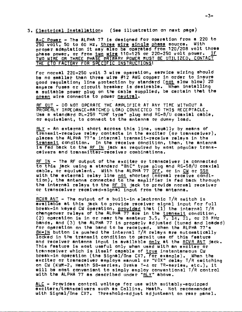
3. E le c t ric a l In s t a lla t io n i (S 9 9 i l lu s tra tio n on next page)
A-C Pomer - The ALPHA 77 is d esign ed f o r o peratio n from a 220 to
250 v o lt, 50 to 60 Hz, thre e w ire s in o le phase source . With
pro p er adapta tio n i t may a lso be o perate d from 120/208 v o lt thre e
phase pouier, or from tuio w ire 110-125 or 220-250 v o lt pouier. !£.
TWO WIRE OR THREE PHASE PRIIHARY POWER fllUST BE U T ILIZED. CONTACT
THE ETO FACTORY FOR SPECIF IC INSTRUCTIONS!
For normal 220-250 v o lt 3 uiire o p e ra tio n, s e r v ice m iring should
be no sm a lle r than thre e mire #12 AWG copper in order to insure
good reg u la t ion i lin e p r o t e c tio n by stan dard ( not slom blom) 20
ampere fus es o r c ir c u i t breaker is d es ira b le . When in s t a lli n g
a s u it a b le pomer plug on the cable supp lie d , be c ertain that the
oreen mire connects to pomer n eu tra l.
RF OUT - DO NOT OPERATE THE AM PLIFIER AT ANY TIME WITHOUT A
PROPERLY IMPE DANCE-MATCHED LOAD CONNECTED TO THIS RECEPTACLE.
Use a sta ndard PL-259 "UHF type" plug and RG-B/U co a x ia l c a b le ,
or e q uivalent, to connect to the antenna or dummy lo a d .
RLY - An e x te rna l short a cross t h is lin e , u s u ally by means of
tra n sm it-receive r e la y contacts in the e xc iter (o r tr a n s c e iv e r),
pla c e s the ALPHA 77's in tern a l transm it-receiv e relays in the
tra n s m it c o n dition . In the r e c e ive c o nd itio n , th e n, the antenna
is fed back to the RF IN jack as required by most p opular tran s
c
eivers and tra n sm itt e r - rece ive r combin ations.
RF IN - The RF output of th e e x c ite r o r t r a n sc e iv e r is connected
to th is jack using a standa rd "BNC" type plug and RG-5B/U co a x ial
cable, or e q uivale nt. W ith the ALPHA 77 OFF. or in CW or SSB
mith the e x te rnal re la y lin e not shorte d (normal receive condi
tio n ), the antenna connected to the a m p lifie r is fed back through
th e in t e r n a l relays to the RF IN jac k to pro vide normal re c e iv er
or tran s ceive r rec e ived - s ign a l input from the antenna,
RCVR ANT - The output o f a b u ilt- i n e le c tron ic T/r srnitch is
a v a ila b le a t th is jack to provide re c e iv e r siqn a l input fo r f u ll
break-in keyed CW o p e ratio n , prov ide d that (1) the inte r n al t /R
changeover re lay s of the ALPHA 77 are in the tra n sm it c ond itio n ,
(2) o p e ration is in o r near the amateur 3 .5 , 7, 14, 21, or 28 MHz
bands, and (3) the ALPHA 77 i s properly ad juste d (tuned and load e d)
for opera tio n on the band to be re c e ive d . When the ALPHA 7 7's
BK»IN button is pushed the inte r n al t/r re la y s are a u to m atic a lly
locked in the tra n sm it cond ition to p ermit use of t h is f e a ture
and re c eive r antenna in p ut is a va i la b le only a t the RCVR ANT jack .
This feature is most useful o nly rnhen used m ith an e x citer or
tran sce iv e r uihich i s i t s e lf capa b le of tru e in stantaneous CW
break-in opera tio n (the Signal/One CX7, for exam ple). When the
e x c ite r or t r a n sc e iv e r employs manual or "U0X" d e lay T/r sm itchin g
on CW (KWM-2, Heath S B-series, Drake T-4 or T R - s e ries, e t c . ) , it
m i ll be most conve nien t to sim ply employ co n v en tio n al T/R c o n tro l
mith the ALPHA 77 as described under " RLY" abo ve.
ALC - Provid e s c o n tro l v o ltage fo r use mith suitably - e q u ipped
e x cite rs/ tra n sc e i v e rs such as C ollin s, Heath. Not recommended
mith Signal/One CX7. T h reshold-adju st a djustment on r e a r p a n e l.
-3-

ALPHA 77 REAR PANEL
INTERCONNECTIONS WITH T R A N S C E I V ER S . TR ANSMITTER S * AND R ECEIV E R S
Warm a ir
exh a u s t
Wain a - c power
input c onn ec t or
P r i mar y li n e f us es
(U s e 15 a m p er e,
s t a nd a r d- blow
on] vi L itt le fuse
ty pe 3AB or B u s s
ty pe ABC)
To an t e n na
(U s e UH F- typ e plug,
PL-259 or eq uiv. ,
wi th 50 ohm c oaxia' l
cable, RG-8A/U or
l a rger)
To t ransceiver " ant enna " —
or trans m i tter "rf ou t
put" c on ne ct o r
(U s e BNC -ty pe plug (UG-
88/U o r aq uiv . ) wi t h
50 ohm RG-58/U cabl e)
ALC t hres ho l d adjust
(Tu r n counter clock
wise t o inc rease
ALC s e n s iti v ity)
ALC cont rol volt age o u t p u t
(U s e ph on o - ty p e s hiel ded
c abl e to c on n ec t to
tran scei v er o r t rans m it
ter " A L C" input j ac k if
des ir ed* Use n o t re co m
mended wi t h C X 7 / CX 7 - A .)
_______
(U s e ph o n o- t y p e cabl e t o c o nn e ct
Ele ctr o n i c T/R s witc h o u t pu t
(U s e phono p l u g wi th 50 ohm coa xi al
c able to pr ovide receiver a n t e n n a
input f or CUI br ea k-i n (" BK I N" mode)
or spec ial pu r pos e s. See te x t.)
i t- re ce i ve relay cont rol
to tran sceiver o r trans m itt er
relay contact s w h i c h ar e open
on receive , sh or ta d on trans m it .
Tay al so be sh or t ad t o pe r mi t
use o f e lec tro ni c T/R swit ch
in "SSB" or "CUT m o d e . )
_5_
SECTION 3
OPERATION
1. C on trol F u nctlo n si
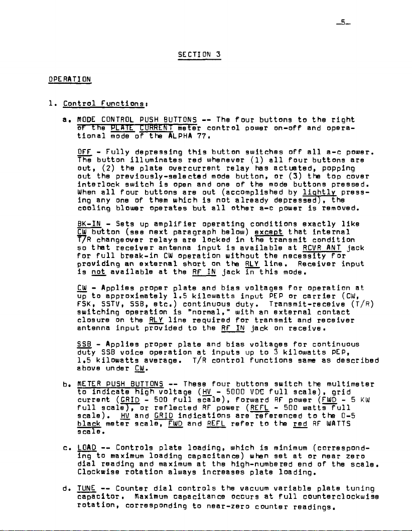
a. NODE CONTROL PUSH BUTTONS — The four button s to the rig h t
of trie HLM Tfc C lIRHLN [ m eter co n tro l pouier on-off and opera
tio n a l mode of the ALPHA 77.
OFF - F u lly depressing t h is b utton switches off a ll a-c pomer.
The button illu m in ates red whenever (1) a l l four buttons are
out, (2) the p late o v e rcurren t re la y has actuated, popping
out the p r e v io u sly - s ele c te d mode b u tto n , o r (3) the top c over
interloc k sw itch is open and one of the mode b uttons p ressed.
When a l l four buttons are out (accomplished by lio h t l y p ress
ing any one of them which is not a lready depressed) , the
cooling blouier o p erates but a l l oth er a-c power is removed.
BK-IN - S ets up a m p lifie r opera ting co n d itions ex a ctly lik e
CIO button (see next paragrap h below) except th a t inte r n a l
T7R changeover re lay s are locked in the transm it c o n d itio n
so th a t r e ce ive r antenna input is a va ilab le a t RCVR ANT jack
for f u l l break-in CW o p e ration w ith out the n e c e ssity fo r
provid ing an e x te rnal short on the RLY lin e . R e ceiver in put
is not a va ilab le a t the RF IN jack in th i s mode.
CW - Applies proper p la te and b ias v o lta g es fo r operatio n at
up to approx imately 1.5 k ilo w atts in put PEP or c a r r ie r (CW,
FSK, SSTV, SSB, e t c .) con tinuous duty. Transmit- receive (T/R)
switching operation is "n o rm al," with an e x ternal c o n tact
clo sure on the RLY line required fo r tran sm it and r e ceiv er
antenna in p u t p rovided to the RF IN jac k on re c e iv e.
SSB - A p p lies proper plate and b ias v o lta ges fo r continuou s
duty SSB v o ice op eration a t inputs up to 3 k ilow atts PEP,
1.5 k ilo w a tts a verage. T/R c o ntro l functio n s same as describ e d
above under CW.
b. BIETER PUSH BUTTONS — These four b uttons sw itch the m u ltimeter
to in dicate high volta g e (HV. - 5000 VDC f u l l s c a le ), grid
curren t ( GRID - 500 f u ll s c a le), forw a rd RF power ( FWD - 5 KW
f u l l s ca le ), or r e fle cted RF power ( REFL - 500 raatts f u l l
s c a le ). HV. and GRID in d ic atio ns are referenced to the 0-5
black meter s c a le, FWD and REFL re fe r to the red RF WATTS
s ca 1 e .
c. LOAD — Controls plate loadin g , w hich is minimum (co rresp o n d
ing to maximum loading capacitan c e ) when s et a t or n ear zero
d ia l read ing and maximum a t the high-numbered end of the s c a le .
Clockw ise ro t a t io n a lways increa se s p la te load ing.
d. TUNE — Counter d ial c o ntrols the vacuum v a ria b le p late tun ing
c a p ac itor, maximum capacitance occurs a t f u l l counte rclo ckw ise
ro t a ti o n , corresponding to near-ze ro counter readings.