

EHRHORN PA-77 Instruction Manual

INSTR UCTIO N AND TECHNICAL MANUAL
IDODEL PA-77 LI N E A R POWER AMP L I FIER
r«C#tt0£Q«$tA* tftft »x v-jK: ...
EHRHORN TECHNOLOGICAL OP ER AT ION S, INC .
BRO O KSVIL L E , FLORID A 33512
No vem ber 1 , 1972
i
TABLE OF CONTENTS
TABLE OF CONTENTS..........................................................................i
STANDARD WARRANTY.......................................................................... i i
SECTION 1 - GENERAL DESCRIPTION AND SPECIFICATIONS. . 1
SECTION 2 - INSTALLATION ......................................................... 2
REAR PANEL INTERCONNECTIONS
..........................
4
SECTION 3 - OPERATION .................................................................. 5
CONTROL FUNCTIONS
................................................ 5
TUNE-UP PROCEDURE ................................................ 6
FINAL OPERATIONAL ADJUSTMENTS, M ON I TOR ING B
PROTECTIVE DEVICES, OPERATING PRECAUTIONS 9
SECTION 4 - MAINTENANCE AND TROUBLESHOOTING..................12
SECTION 5 - THEORY OF OPERATION............................................14
SECTION 6 - ILLU ST RA TION S.........................................................19
TOP V IE W ....................................................................19
BOTTOM V IE W ............................................................. 20
REMOVAL OF POWER SU P P LY
...................................
21
CIRCUIT DIAGRAM (SC H EM A T IC )
..........................
22
EHRHORN TECHNOLOGICAL OPERATIONS, INC.
i i
STANDARD WARRANTY
EHRHORN TECHNOLOGICAL OPERATIONS, INC. (ETO) m arrants each nan
product m anufactured by it to be fre e from d efe c tive m a te r ial or
morkmanship and agrees to remedy any such d e fe ct or to fu rn is h a
nem p art in exchange fo r any p a rt o f any u n it of it s m anufacture
which under normal in s t a lla tio n , use, and s erv ic e d isc lo s e s such
d e fe c t, provided the u nit is d e livere d by the omner to us or to
our autho rize d dea ler or d is tr ib u to r from mhom purchased, in t a c t,
fo r our exam ination, roith a ll tra n sp o rta tion charges p repaid,
u/ithin ninety davs from the date of sa le to o rig in a l purchaser,
provided th a t (1 ) such exam ination d is c lo s e s in our judgment th at
i t is thus d e fe ctive and that (2 ) a p ro p e rly completed marranty
re g is tra t io n form has been m ailed to ETO m ithin f iv e (5 ) days
a fte r date of sale to o r ig in a l purchaser.
NOTEi Do not under any circum stances raturn equipment to ETO
m ithout rec e iv in g e x p lic it a u th o r iza tio n fo r such
return from us in advance. Shipment of equipment in
other than approved fa c to ry packing may v o id th is mar-
ra n ty. Should a m alfu n ction be suspected, co n ta ct your
s e llin g d ea ler or the ETO se rvice department m ith f u l l
d e t a ils of the d iff ic u l t y b efore attem pting re p a irs or
retu rn fo r a e rvic e .
This m arranty does not extend to any of our products mhich have
been subjected to m isuse, n e g le c t, accid e n t, in c o r re c t m iring
not our omn, improper in s ta lla tio n , or to use in v io la tio n of
s p e c ific a tio n s and in s tru ctio n s furn ish e d by us, nor to units
mhich have been rep a ired or a lte re d ou tside our fa c to ry , nor in
cases mhere the s e r ia l number there o f haa been ramoved, a lte r e d ,
or defeced, nor to u n ita used m ith a ccess o ries not m anufactured
or recommended by u s, nor to the high pomer tran s m ittin g tu b e (s ).
Tran sm ittin g tubee are m arranted by th e ir m anufacturer and the
m arranty is adm inistered by ETO.
This marranty is in lie u of a l l o ther m arranties expressed or
im plie d and no re p re s e n ta tive or peraon is au th orized to assume
fo r ETO any othe r l ia b i l i t y in connection m ith the sale of our
products.
ETO re serve s the rig h t to make such changes or improvements to
it s products mhich i t may deem d e s ira b le , m ithout o b lig a ting
it s e lf to make such changes or improvements a v a ila b le fo r it s
p reviou s ly manufactured pro ducts.
EHRHORN TECHNOLOGICAL OPERATIONS, INC.
BROOKSVILLE, FLORIDA
-2-
5ECTI0N 2
INSTALLATION
1. Unpacking i Open th9 marked end of both o uter and inner carton s
and c a re f u lly remove the p lastic-tiirapped a m p lifie r. I f d i f f i
cu lty is exp erienced, it may be necessary to also open the op
posite end of both cartons so th a t the u n it may be pushed out.
SAVE ALL PACKING MATERIAL FOR RE-USEi ANY SHIPMENT OF THE ALPHA
77 IN OTHER THAN FACTORY-DESIGNED PACKING MAY VOID THE WARRANTY.
C a re fu lly ins p e c t fo r shipp ing damage. Remove the s in g le screui
securing the top cover and s lid » the cover open. REMOVE THE FOAM
BLOCK WEDGED BETWEEN THE PLATE COIL AND THE A IR EXHAUST ASSEMBLY.
To insu re th at the BB77 am p lifie r tube is prop erly seated in it s
so cket, grasp the s ta in le s s s te e l anode clamp rin g securing the
bottom of the rad s ilic o n e rubber a i r exhaust hood and preas firm
ly domnmard. The hood should be amooth and fre e of m rin k les.
Make c e rta in th a t the vacuum v a ria b le ca p acito r (in the lom er,
right-h and corner of the r f compartment) ia aecurely fastened and
operates smoothly mhen the "TUNE" crank is ro ta ted .
In the event of damage, n o tify the tra n s p orta tion company immedi
a te ly . Complete and m ail the m arranty re g is t r a tio n form to ETO
m ithin 5 day at no marranty claim (s ) can be con sidered o therm ise.
Cloae and faste n the top co ver, confirm ing th a t i t a re a r li p con
ta c ts and actu ates the a-c in te r lo ck near the cool a ir intak e .
2. P h ys ic a l In s t a l la t io n ! The ALPHA 77 must be loc ated so th a t
intake of cool a ir and exhaust of hot a ir behind the re a r panel
is not impeded in any uiay, and so th a t hot a i r exhaust m ill not
s ig n ific a n tly r e c ir c u la te in to the co ol a ir inta k e . Under no
circum stan ces should the back of the a m p lifie r be le s s than s ix
inches from any m a ll, d ra p e ries, or other o b s tru c tio n s. A two-
inch copper "bend” or elbom, e ith e r 22^° or 45° "DfflV" type as
a v a ila b le from plumbing supply houses, may be used to d e fle c t
the exhaust a ir floui i f n ece ssa ry.
Room h eating may be v ir t u a lly e lim inated as a by-product of
a m p lifie r o p e ra tio n , and c ooling system noise even fu rth er cu t,
i f exhaust a ir is ducted outdoors using a s u ita b le duct not le s s
than three inches in in sid e d iam eter. S ig n ific a n t back pressure
must not be g enerated! e le c t r ic d ry er ven t f i t t in g s uiith magnetic-
latc h ing outside f la p s , fo r example, are in t o le ra b le , as they
m ill prevent adequate a ir flo w and may re s u lt in seriou s damage
to the tube and the a m p lifie r. Normal blouier speed should be
increased s lig h tly mhen exhaust a ir is ducted more than a fetu
inch es; check m ith your d ealer or the E.T .O . fa c to ry fo r ad v ic e .

-2-
5ECTI0N 2
INSTALLATION
1. Unpacking i Open th9 marked end of both outer and inner cartons
and c a re f u lly remove the p lastic-tiirapped a m p lifie r. I f d i f f i
cu lty is exp erienced, it may be necessary to also open the op
posite end of both cartons so th a t the u n it may be pushed out.
SAVE ALL PACKING MATERIAL FOR RE-USEi ANY SHIPMENT OF THE ALPHA
77 IN OTHER THAN FACTORY-DESIGNED PACKING WAY VOID THE WARRANTY.
C a re fu lly ins p e c t fo r shipp ing damage. Remove the s in g le screm
securing the top cover and s lid » the cover open. REMOVE THE FOAM
BLOCK WEDGED BETWEEN THE PLATE COIL AND THE A IR EXHAUST ASSEMBLY.
To insu re th at the BB77 am p lifie r tube is prop erly seated in it s
so cket, grasp the s ta in le s s s te e l anode clamp rin g securing the
bottom of the rad s ilic o n e rubber a i r exhaust hood and preas firm
ly domnmard. The hood should be amooth and fre e of m rin k les.
Make c e rta in th a t tha vacuum v a ria b le ca p a c ito r (in the lorner,
right-h and corner of tha r f compartment) ia ae curely fastened and
operates smoothly rnhen the "TUNE" crank is ro ta te d .
In the event of damage, n o tify the tra n s p orta tion company immedi
a te ly . Complete and m ail the uiarranty r e g is t ra t io n form to ETO
rnithin 5 dayai no uiarranty cla im (s) can be con sidered o the rw ise.
Cloae and faste n the top co ver, confirm ing th a t i t a re a r li p con
ta c ts and actu ates the a-c in te r lo ck near the cool a ir intak e .
2. P h ys ic a l In s t a l la t io n ! The ALPHA 77 must be loc ated so th a t
intake of cool a ir and exhaust of hot a ir behind the re a r panel
is not impeded in any uiay, and so th a t hot a i r exhaust m ill not
s ig n ific a n tly r e c ir c u la te in to the co ol a ir inta k e . Under no
circum stan ces should the back of the a m p lifie r be le s s than s ix
inches from any m a ll, d ra p e ries, or other o b s tru c tio n s. A two-
inch copper "bend” or elbom, e ith e r 22^° or 45° "DfflV" type as
a v a ila b le from plumbing supply houses, may be used to d e fle c t
the exhaust a ir flom i f n e ces sary.
Room h eating may be v ir t u a lly e lim inated as a by-product of
a m p lifie r o p e ra tio n , and c ooling system noise even fu rth er cu t,
i f exhaust a ir is ducted outdoors using a s u ita b le duct not le s s
than three inches in in sid e d iam eter. S ig n ific a n t back pressure
must not be g enerated! e le c t r ic d ry er ven t f i t t in g s uiith magnetic-
latc h ing outside f la p s , fo r example, are in t o le ra b le , as they
m ill prevent adequate a ir flo w and may re s u lt in seriou s damage
to the tube and the a m p lifie r. Normal blomer speed should be
increased s lig h tly rnhen exhaust a ir is ducted more than a fetu
inch es; check m ith your d ealer or the E.T .O . fa c to ry fo r ad v ic e .
-3-
3. E le c tr ic a l In s t a lla tio n i (S 9 9 il lu s t ra t io n on next page)
A-C Pomer - The ALPHA 77 is designed fo r o p eration from a 220 to
250 v o lt , 50 to 60 Hz, three w ire s in o le phase source. W ith
proper ada p tation i t may also be operated from 120/208 v o lt three
phase pouier, or from tuio w ire 110-125 or 220-250 v o lt pouier. !£.
TWO WIRE OR THREE PHASE PRIIHARY POWER fllUST BE UTILIZED . CONTACT
THE ETO FACTORY FOR SPEC IFIC INSTRUCTIONS!
For normal 220-250 v o lt 3 uiire o p eration , se rv ice m iring should
be no sm a ller than three m ire #12 AWG copper in order to insure
good reg u latio n i lin e p ro te ctio n by standard ( not slom blom) 20
ampere fuses o r c irc u it breaker is d e sira b le . When in s ta llin g
a su ita b le pomer plug on the cable su p p lied , be c e rta in th a t the
oreen mire connects to pomer n e u tra l.
RF OUT - DO NOT OPERATE THE AMPLIFIER AT ANY TIME WITHOUT A
PROPERLY IMPE DANCE-MATCHED LOAD CONNECTED TO THIS RECEPTACLE.
Use a standard PL-259 "UHF typ e" plug and RG-B/U co ax ia l cable,
or e q u iva len t, to connect to the antenna or dummy load.
RLY - An extern a l short acro ss th is lin e , usu a lly by means of
tran sm it- re c e ive r e la y co n tacts in the e x c ite r (o r tra n s c e iv e r),
places the ALPHA 77's in te r n a l tra n sm it-rece ive re la ys in the
tran sm it co n d ition . In the receive c o n d ition , then, the antenna
is fed back to the RF IN jack as required by most popular tr a n s
c
eive rs and tra n sm itter- rece iv e r com binations.
RF IN - The RF output of the e x c ite r or tra n s ce iv e r is connected
to th is jack using a standard "BNC" type plug and RG-5B/U c o a x ia l
ca b le, or e q u iva le n t. With the ALPHA 77 OFF. or in CW or SSB
mith the e x te rn a l re la y lin e not sh orted (normal receive con d i
tio n ), the antenna connected to the am p lifie r is fed back through
the in te r n a l rela y s to the RF IN jack to provide normal re c e ive r
or tra n s c e iv e r receive d -sign a l input from the antenna,
RCVR ANT - The output of a b u ilt- in e le c tro n ic T/r srnitch is
a v a ila b le a t th is jack to provide re c e ive r siq n a l inpu t f o r f u l l
break -in keyed CW o p e ra tion, provid ed th a t (1) the in te rn a l t /R
changeover re la y s of the ALPHA 77 are in the tran sm it con d ition ,
(2) o p eration is in or near the amateur 3 .5, 7, 14, 21, or 28 MHz
bands, and (3 ) the ALPHA 77 is p ro p e rly ad justed (tuned and loaded)
fo r o p eration on the band to be re c e iv e d . When the ALPHA 7 7's
BK»IN button is pushed the in t e rn a l t/ r r e la y s are au to m atically
locked in the tra n s m it co n ditio n to permit use of th is fea tu re
and re c e iv e r antenna in put is a v a ila b le only a t the RCVR ANT ja c k .
Th is fe a tu re is most u s e fu l only rnhen used m ith an e x c ite r or
tra n s c e iv e r uihich i s i t s e l f capable of tru e in stantan eou s CW
break -in operation (th e Signal/One CX7, fo r exam ple). When the
e x c ite r or tr a n s c e ive r employs manual or "U0X" delay T/r sm itching
on CW (KWM-2, Heath SB -serie s , Drake T-4 or T R-series , e t c . ) , it
m ill be most convenient to simply employ co n ve n tional T/R c o n tro l
mith the ALPHA 77 as d escribed under " RLY" above.
ALC - Pro vide s c on tro l vo ltag e fo r use mith su itab ly- equipped
e x c ite rs / t ra n s c e iv e rs such as C o llin s , Heath. Not recommended
mith Signal/One CX7. Thresh old-ad just adjustm ent on re a r pan el.

ALPHA 77 REAR PANEL
INTERCONNECTIONS WITH T R A N S C E I V ER S . TR ANSMITTER S * AND RE CEI V E R S
Warm a ir
exh a u s t
Wain a - c power
input c onn ec t or
P r i ma r y li n e fuse s
(U s e 15 a m p er e,
s t a nd a r d- blow
on] vi L ittle fu se
ty pe 3AB or B u s s
ty pe ABC)
To an t e n na
(U s e UH F- typ e plug,
PL-259 or eq u iv.,
wi th 50 ohm c oaxia' l
cabl e, RG-8A/U or
l a rg e r)
To t ran sceiver "a nte nna" —
or transm i tter "r f ou t
put" c on ne ct o r
(U s e BNC -ty pe plug (UG-
88/U o r aq u iv.) wi t h
50 ohm RG-58/U cabl e)
ALC t hres hol d adjust
(Tu r n countercl ock
wise t o incr ease
ALC s e n s itiv ity )
ALC cont rol vol tage o u t p u t
(U s e ph on o - ty p e s hi el ded
c abl e to c on n ec t to
tran sceiver o r transm it
ter " A L C" input j ac k if
des ir ed* Use n o t re co m
mended wi t h C X 7 / CX 7 - A .)
_______
i t- rece ive rel ay c ontrol
(U s e ph o n o- t y p e cabl e t o c o nn e ct
to tran sceiver o r tr ansm itt er
relay cont acts wh ic h a re open
on recei ve, sh or ta d on transm it .
Tay al so be sh or t ad t o pe r mi t
use o f e lectro n ic T/R s w i tc h
in "SSB" or "CUT m o d e . )
Ele ctro ni c T/R swit ch o ut p ut
(U s e phono p l u g wi th 50 ohm coaxial
c able to pr ovide rece iver a n t e n na
input f or CUI br eak -i n ("BK I N" mode)
or speci al p urpos e s. Se e te x t.)
_5_
SECTION 3
OPERATION
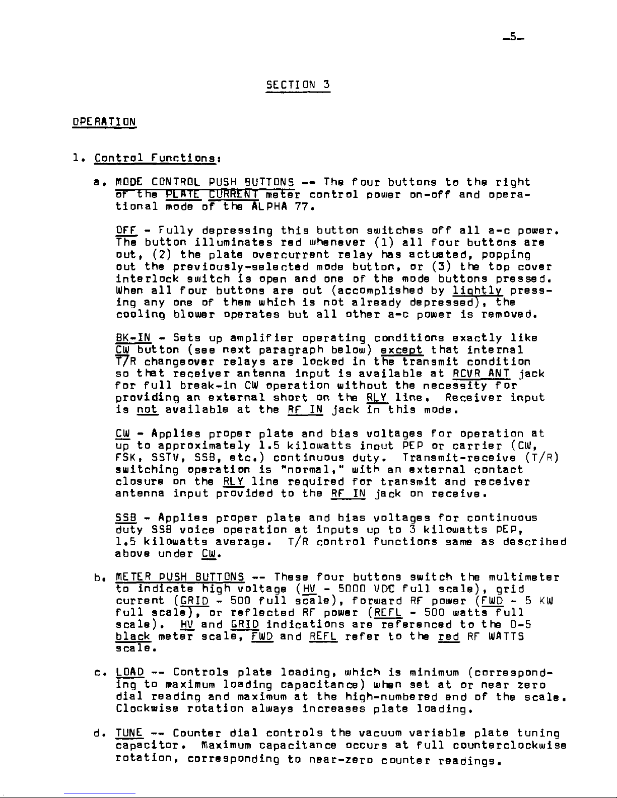
1. Control F u n ctlon si
a. NODE CONTROL PUSH BUTTONS — The four buttons to the r ig h t
of trie HLM Tfc C lIRHLN [ meter c o n tro l pouier on-off and opera
tio n a l mode of the ALPHA 77.
OFF - F u lly depressing t h is button sw itches o ff a l l a-c pomer.
The button illu m in a te s red whenever (1 ) a l l fou r buttons are
out, (2) the p late o ve rcurrent re la y has a c tu a te d , popping
out the p re v io u s ly - s e le c te d mode button, or (3) the top cover
in te r lo ck sw itch is open and one of the mode buttons pressed.
When a l l four buttons are out (accom plished by lio h tly press
ing any one of them which is not alread y depressed) , the
co oling blouier operates but a ll other a-c power is removed.
BK-IN - Sets up a m p lifier op erating co n d ition s e x a c tly lik e
CIO button (see next paragraph below) except th at in te rn a l
T7R changeover re lay s are locked in the tra n sm it co n d ition
so th at r e ce iv e r antenna inp u t is a v a ila b le at RCVR ANT jack
fo r f u l l break-in CW o pera tion w itho ut the n ece ssity fo r
provid ing an e xte rn a l sh o rt on the RLY lin e . R ece iver input
is not a v a ila b le at the RF IN jack in th is mode.
CW - A pp lies proper p late and b ias vo ltages fo r o peration at
up to app rox im ately 1.5 k ilo w a tts input PEP or c a r r ie r (CW,
FSK, SSTV, SSB, e tc .) continuous d uty. T ransm it-re ceive (T/R)
sw itching operation is "n o rm al," with an e x ternal c ontact
closure on the RLY lin e re q u ired fo r tra n sm it and re c eive r
antenna input provided to the RF IN jack on re ce iv e .
SSB - A p p lies proper p late and bias vo ltages fo r continuous
duty SSB vo ice o p eration a t inputs up to 3 k ilo w atts PEP,
1.5 k ilo w a tts average. T/R co n tro l fu n c tio n s same as described
above under CW.
b. BIETER PUSH BUTTONS — These four buttons sw itch the m ultim eter
to ind ic a te high v o ltage (HV. - 5000 VDC f u l l s c a le ), g rid
cu rrent ( GRID - 500 f u ll s c a le ), forward RF power ( FWD - 5 KW
f u ll sc a le ), or re fle c te d RF power ( REFL - 500 raatts f u ll
s c a le ). HV. and GRID in d ica tio n s are referen ced to the 0-5
black meter s c a le , FWD and REFL re fe r to the red RF WATTS
s ca 1 e .
c. LOAD — Controls p late loa d ing , which is minimum (correspond
ing to maximum loading cap acitan ce) when set at or near zero
d ia l reading and maximum a t the high-numbered end of the s c a le .
Clockwise ro ta tio n always incre a ses p late loading.
d. TUNE — Counter d ia l co n tro ls the vacuum v a riab le p la te tuning
c a p a c ito r, maximum ca pacitance occurs at f u ll counterclockw ise
ro ta tio n , corresponding to near-zero counter rea d ings .
 Loading...