

EHRHORN ALPHA 77Sx, ALPHA 77Dx Operating And Technical Manual

PRICE: $10.00
O P E R AT ING AND TE CHNI CAL MANU AL
HIGH FREQUENCY LINEAR POWER AMPLIFIERS
ALPHA 77Dx and ALPHA 77Sx
EHRHORN TECHNOLOGICAL OPERATIONS, INC.
JANUARY 1990
IMPORTANT
SERVICE ASSISTANCE
To help you secure technical assistance without wasted long distance calls, ETO
has established a special SERVICE telephone line WHICH WILL BE ANSWERED
ONLY WHEN A QUALIFIED SERVICE TECHNICIAN IS AVAILABLE TO HELP
YOU IMMEDIATELY.
The special service number is (719) 599-3861. If your call to this number is NOT
answered it indicates that no qualified technician is free to talk with you at the
moment. Please wait a few minutes and try again. NOTE ALSO that business
hours are 8:30 A.M. to 4:30 P.M. MOUNTAIN TIME Monday through Thursday.
If your call does NOT relate to service or other technical matters, our business
office staff will be happy to help you at the number shown on the rear cover of
this manual.
TEN METER OPERATION OF YOUR ALPHA
FCC rules permit an appropriately licensed amateur to modify his own amplifier
for operation on 28-29.7 MHz. We strongly recommend that you contact our
service department before attempting any modification. (If you enclose your
request and a photocopy of your valid amateur radio license with the warranty
registration card for your new amplifier, appropriate information will be sent
without charge.)
THE EXPECTED NEW 10, 18 and 24 MHz AMATEUR BANDS
If and when FCC permits amateur use of these bands with linear amplifiers,
your ALPHA will be capable of 10 and 18 MHz operation with only slight modi
fication. In the somewhat unlikely event that high power operation is eventually
permitted on 24 MHz, ETO may make available information to permit safe operation
of your ALPHA on that band. ANY ATTEMPT TO OPERATE YOUR ALPHA IN
THE VICINITY OF 24 MHZ WITHOUT APPROPRIATE MODIFICATION MAY
CAUSE SERIOUS DAMAGE.
1/90

TABL E O F CONTE NT S
SECTI ON 1 - GENERAL DE SCRIPT ION & SPEC IFIC ATIO NS
.........
1
SECTI ON 2 - IN STAL LAT ION
...............................
2
Electric al Installation (AC Powe r Wir in g ) . . . 2
RF and Contro l Conne cti ons
..................
5
SECT IO N 3 - OPERATI ON
.................................
8
Contr ol Posit io ns .......................... 8
Tune- up Proce du re . .
......................
9
Final Operati ona l Adju stm ents «Sc Monitoring . . 11
Oper ati ng N o t e s
.........
................
1 2
Troublesho oting Hi nt s . ...................
1 4
SECTI ON 4 - THEOR Y OF OPER A T ION
......................
1 6
SECTIO N 5 - ILLUSTRATIONS
...........................
21
Fron t Pan e l ; Rear Panel ...................
21
Front Su b- pa ne l; Ba c k Sid e of Fron t Panel . . 2 2
RF Sect i o n, Top and Si d e , Cov er s Remove d . . 23
Power Supply Se c ti on , Sid e and Obl iq u e .... 24
Tu be Dec k, Und er s id e; Circui t Boar d CB-2 . „ . 2 5
Circu it Boar d CB- 3 ; Wattmeter „ . . . . . . . 26
Sch e ma ti c, RF Section & Tu be D e c k
.........
2?
Sch em at ic, Power Supply & Main C ha ss is .... 28
Sch e ma ti c, Front Panel
....................
29
Sch em at ic , Circu it Boa rd CB-2
.............
3°
Sch em at ic , QSK Circ uit Bo a rd CB-3
.........
31
SECTION 6 - STAND ARD ELECTRICAL P ART S L I ST
.............
32
ET0/ "AL PHA " PRODUCT WARRANTY
...........
Ou ts i de Bac k Cover
EHRHORN TECHNOLOGICAL OPERATIONS, INC.
4975 NORTH 30TH STREET
COLORADO SPRINGS, COLORADO 80919 U.S.A.
REV. 1/90 @ U.S.A.
I
SECTIO N 1
GENER AL DES CRIPT ION
Th e ALPHA 77D x (ty p e accepted mo del PA-77DF a nd governme nt/ expo rt
mode l PA- 7 7 D x ) * is a high power HF linear amplifier of excepti ona l
qu al it y , rug ge dn es s, and sophistic ated de s i g n . I t i s much smal le r
tha n othe r ampl if ier s of compa rab le capab i li ty , yet pr ovi de s great
er operat ion al vers at ili ty, co ol er op er at i on , and a lower acousti
ca l noise lev el than much larger and heavi er u n i ts .
Uni qu e desi gn featu re s of th e ALPHA 7?D x incl ud e ETO' s excl usi ve
full- cabi net ducte d air cooling sys t em , built -in CW break- in key
ing s y s t e m, fr eque ncy cove rag e dow n t o 1. 8 MH z , and a highly effi
cie nt custom powe r transfo rmer using a tape-w oun d core of grain-
ori ent ed silicon st ee l . High efficien cy of operati on is maint ained
acr os s the tunin g ra nge by a combin ati on of vacuum var iabl e out pu t
tuni ng capaci tor and ET O's expertly de sig ne d mix ture of silver plat
e d, heavy copp er tubing coi l s and mu lti -i nsu lat ed , toroidal ind uc t or s .
SPECIF ICAT IONS (M o d e l s PA-77DF and PA -7 7D x )
Frequency Coveragei 1.8-2.0 and 3-24 MH z (* 2 4 -3 0 M H z , PA-77Dx on l y ) .
Plat e Power Input» PA-77DF 2.5 KW PEP / SS B , 1 KW ave rage d- c , all
mo d es , no time li m i t» PA-77Dx 3* 5 KW PEP , 2 KW d- c ave ra ge , N T L .
Plat e Efficiency» Typically 60# or b e t t e r.
Drive Poweri Nom inal 60- 7 0 watt s ca r ri e r , 10 0- 150 wat ts P E P .
Inpu t & Out put Impedances» Nominal 50 ohm s unbalanced * VSWR under 2* 1.
Distortion: Th ird order IM mo re than 36 dB below 1. 5 KW PEP ou t p u t .
Harmonics» More tha n 50 dB belo w mean fund ame nta l frequency out p u t .
Tub e Complement» On e Eimac 8877 cera mi c tri o d e, ground ed gr i d .
Cooling» Full-cabi net ducted forced air j ball bearing cen tr i f. b l o we r .
ALC» Adjusta ble-t hres hold , grid- cur ren t- der ive d, negative goi n g .
Protection» Primary and step-star t fu se s , pl at e overc urr ent sole no i d,
a-c li n e and high volt age cover interlocks.
Primary Power» 220- 250V wit h ground ed cent er n eu t ra l, 50-60 Hz, stan
dar d . Sim pl e re-connection a ccom moda tes 110 -1 2 5 V, 120-2 08 V, o r
220-25 0V without center n e ut ra l . 240V supply wi th 20A fuse s or
slow bre ake rs i s adequa te fo r all-mod e operat io n at full rat in g s.
Size & Weight» ll " h . x 19 " w . x 22 " d. ( 28 x 48 x 56 cm ). Net weigh t
95 lb. (43 k g) , shipping we igh t 125 ( 57 kg) in tw o ca rt o n s .
VARIA TION S FOR GOVERNMENT/EXPO RT-ONLY MODE L ALPHA 77S x (PA-77Sx)t
Sam e as ALPHA 77Dx ( PA - 7 7 D x ) above exc ep t tw o 88 7 7 tubes perm it
great er PEP inpu t and outpu t po w e r. Ap prox imat ely 17 5 wat ts
dri ve for maximum out p u t. Ne t w t . 10 5 l b. (48 kg ) , shipping
weight 130 l b. (59 kg) .
*N0TE: Only FCC type-accepted model PA-77DF may legally be sold within the U.S,
except to government customers. PA-77Dx £ PA-77Sx available only for
export and government customers.
-1-
SECTI ON 2
TNSTALLATT ON
1. Unpacking: Carefull y rem ov e amplif ier and tra nsf orme r from car
t o n s; SAVE ALL PAC KING MATE RIAL F OR RE -US E — SHIPMENT OF ALP HA
77 DX I N OTH E R THA N FACTORY PAC KIN G MAY RES UL T I N DAMA GE NO T COVE RE D
UNDER WARRA NTY ©£©
Rem ov e top cov er and ins ur e th at both plug -in circu it hoa rd s are
firmly seat e d in thei r soc k e t s. Confir m th a t the TUNE contr ol
op er at e s smoot hly an d rea ch es a firm mechani cal stop at it s ful l
clo ck wi se ro t at i o n. If you r TUN E count er reading dec re as es with
clo ck wi se ro ta t i on , i t shou ld stop "between 000 an d 010; i f i t is
a typ e th a t incre as es with cloc k wi se rotati on of th e c r a n k , it
shou ld st op nea r 19 0 - 2 0 0 . Ther e is no hard stop at full counter
clo ck wi se rotat ion and cauti on mu st be used t o avoid turning t h e
cra nk beyo nd the norma l en d of rota tion (co un t er reading o f
appro xima tely 24 0 or 0 0 0, depend ing on typ e as abo v e ) .
Ins pe ct ins i d e and ou t closel y for evide nc e of shippin g d a ma g e ;
if any i s fo u n d , notify deliv ering carr ie r at on ce . Com pl et e
the encl o se d warran ty reg istr atio n form an d mail i t to ET 0 . ©
2. Transfo rmer Installation: Or ie nt the transf orme r so that the tw o
mul ti -p in , molded plu gs on the transformer h ar ne ss point towar d
the rear of t he amp li f ie r; mov e the corresp ondin g mating connect
o r s i n th e amplifie r ou t of the wa y, and ma ke cert ai n tha t th e
trans for mer moun ting ar ea i s clea r of packing material and all
wi r e s . USE EXTREM E CAUTION L OWERING TH E TRA NSFOR MER INT O PLAC E
TO AVOID DA MAG ING ADJA CENT COMP ONE NT S OR WI RI N G. It may be de
sira bl e to rig a simp l e slin g of
strong co r d or gla s s fila men t tap e to aid in suppor ting an d con
trolling t h e heavy tr ansfo rmer whi le lower ing it in t o pl a c e .
Inst al l th e bolt s provi ded to secu re th e tra ns fo r me r. Check bot h
pai rs of conn ec to rs visually fo r prope r mating orie nta tion (a v o i d
exc ess iv e harn es s bending or twi st i ng , as i t may cau s e dam a ge to
wire s or conne cto r p i ns ) and mat e them fi r ml y , pushing unt il th e
integ ral lat c h e s eng a g e . Ins u re tha t all wir es are dressed we ll
clea r o f th e HV rect ifie r boar d an d HV-shor ting crowb ar swi t c h .
Make certa in t ha t th e crowba r arm swi n gs fre e l y. TH I S CROWBA R
I S AN IMP ORT AN T SAFETY FE A TU R E; DO NOT DISABLE IT AND D O NO T ©
APPLY A C POWE R TO THE A MPLIFIER WIT H THE COVE R OP E N.
3» Electr ical Installation: T h e ALPHA 77D xa nd 77S xa re normally ship
ped wir ed for U.S.-standar d 120/240V (1 20 - N - 12 0 ) , 3 w i r e , 5 0 -6 0
Hz , sin gl e pha se power (gr o un d ed ne ut ra l) . If the amplifie r i s
to be used with t hi s servic e configur atio n or has been fact or y-
conn ect ed for y our al tern ate arr an ge me nt , th e top cov er may b e
repla ced and sec u r ed . If change -ove r t o op e ra te on 220-250V
without center ne ut r al , or on 110-125V s er v ic e , is nece ss ar y ,
procee d as fol lo ws fir s t *
Re-connec tion for opera tio n on 220-250 V w ith out center neutral -
(a) Locat e the 7-lug t ie strip a t th e righ t , rear of the cabi
ne t , alo ng th e right ed g e of th e circ ui t board she l f . Th e
lu g s o n t hi s strip (TS -1 ) are numbered from # 1 at front to
-2
#7 at the ba ck . Th e standard wiring to TS-1 (fo r 120/240V
with cent er neut ral) is as follow s* (S ee Fig . 1, page 4 )
LUG 1 — Ground (moun ting foot for terminal stri p )
LUG 2 — White/black wire
LUG 3 — White wire
LUG 4 — Gre en , re d, white/green & white/orange wire s *
LUG 5 — White/violet wire and on e blower wire ( gr ay or blk )
LUG 6 — Black wire *
LUG 7 — Ground fo ot ; gray wires
* A tubular capacitor is connected also from #4 to # 6 .
( b) Remo ve the white/green wire only from LUG 4 and con
nect it instead to LUG 2 . (Se e Fi g. 2, page 4 )
( c) Add a new resistor (7 0 0 ohm s, 8 to 1 2 watt) between
LUG 3 and LUG 4 ; keep it clear of all wires and par ts .
( d) Rem ove the cover from the 6 pin connector on the AC
power cab le ; remove the wire jumpe r connected between
pi ns 10 and 11. Pin 11 is then blank and unu se d; onl y
the green power cabl e wire (ch ass is) goes to pin 1 0 .
( e) Repl ace power connector cover and amplifier top cov er .
( f) The 240V service wires connect to black and white wires
of the cabl e ; green goe s to ground only.
Re-connection for operation on 110-125V service - All required
re-connections are made inside the power cable connector itse lf ;
remove its cov er . ( S e e Figure 5» page 4)
*
( a) Remove th e existing jum per wire between pins 7 and 9 «
Remove also the jump er wir e between pins 10 and 1 1 .
( b) Add a new jumpe r wire from pin 7 through pin 12 and on to
pin 11. Add another jumpe r wire from pin 8 to pin 9.
Replace cap on conn ect or.
( c) The 120V AC service wires connect to the black (from pins
8 & 9 ) and white (f ro m pin s 7i 1 1 » & 12 ) power cable wir es.
The green wire ( ch as si s) connects to power system groun d.
For informa tion on use with any other type of primary mains con
figu ratio n, co ntac t ET0 facto ry.
Power Cabl e Connection s - The green wire in the main amplifier
AC power cable i s connected to chassis and must always (a n d only!)
be wired t o the AC mains ground (or center neutral with U. S. stan
dard 120-N -120V system). The black and white wires ar e inter
changeab le and conne ct to the two "h ot " wires of the se rvi ce .
Service wiring should be at least #12 AWG cop per , protected by
fuse s or breaker rated at 20 to 30 amperes ( #1 0 AW G, 30 ampere
fuse s or breaker for PA-77SjJ .
4 . Physical Location: T he amplifier must be positioned horizontally,
and so that the intake of cool air and exhaust of hot air i s not
impeded in any w ay , and so that hot exhaust air cannot signifi
cantly recircula te back into the cool air intake are a. A minimum
of six inches cleara nce should be allowed behind the ampli fier,
with open ac ces s to surrounding air unless special ducting pro
visio ns are provi ded .
-3
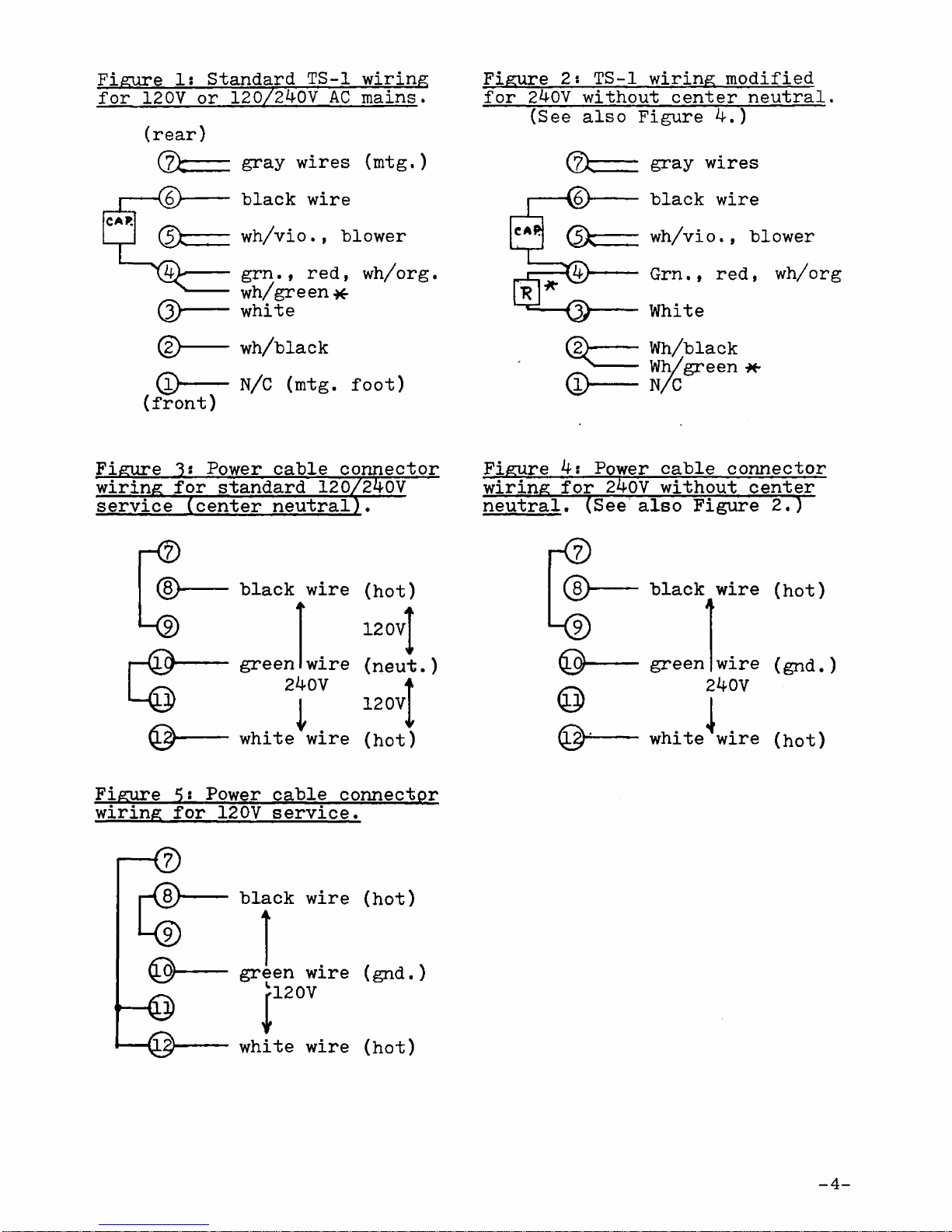
Figure 1 : Standard TS-1 wiring
for 120V or 120/240V AC mains.
(r e a r )
d>
©—
(f r on t )
gray wire s (mtg.)
black wire
wh/v io., blower
grn., red,
wh/green*
white
wh/black
wh/org.
N/C ( m t g . foo t)
Figure 2 : TS-1 wiring modified
for 240V without center neutral.
(S e e also Figure 4. )
(zfc
<k
© -
gray wire s
black wire
w.
h/vio., blowe r
Grn., red, wh/org
White
Wh/black
Wh/green *-
N/C
Figure 3 ? Power cabl e connector
wiring for standard 120/240V
servi ce (c ent er neutral).
-< 2 >
d>
L ®
r © -
black wire
a
green
wire
240V
( h o t )
120vT
(n eu t
12 0 V
)
white wire ( h o t)
Figure 4: Power cable connector
wiring for 240V without center
neutr al" (Se e also Figure 2 . )
- 0
d>
© -
black wire (h o t )
A
green
wire (gnd.)
240V
i
white wire ( h o t)
Figure 5 : Power cable connector
wiring for 120V serv ice .
-d >
k D
© -
black wire (h o t )
green wire (g n d .)
|!2°V
white wire (h o t )
-4 -
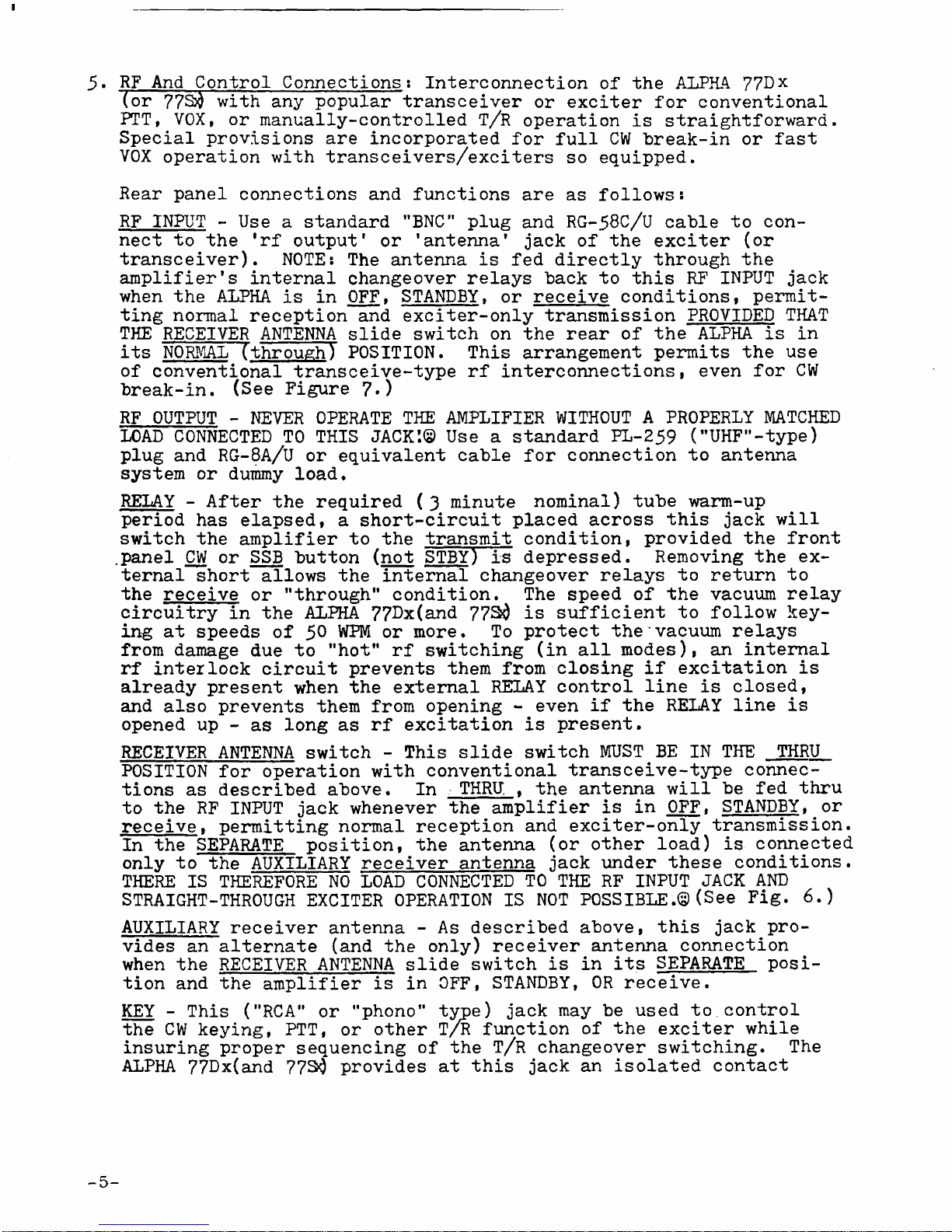
5 . RF And Control Connections: Interconnection of the ALPHA 77Dx
( o r 77 S$ with any popular transceiver o r exciter for convent ional
PT T , VO X , or manually-controlled T/R operation is strai ghtfor ward.
Speci al provi sions ar e incorporated for ful l CW break-in o r fast
VOX operation with transceivers/exciters so equip ped .
Rear panel connec tions and functions are as follow s:
RF INPUT - Use a standard "BN C " plug and RG-58C/U cable to con
nect to the ' r f out pu t' or 'a n te n na ' jac k of the exciter (o r
trans ceiv er). NOT E : The antenna is fed directly through the
ampli fier' s interna l changeover relays back to thi s RF INPUT ja c k
when th e ALPHA i s in OFF, STANDBY, or receive condit ions, permit
ting normal reception and exciter-only transmission PROVIDED THAT
THE RECEIVER ANTENNA sli de switch on the rear o f the ALPHA i s in
it s NORMAL Tthrough) POS ITIO N. Th is arrangement permits the use
of conventional transceive-type rf interconnecti ons, ev en for CW
bre ak -in . (S e e Figure 7 - )
RF OUTPUT - NEVER OPERATE THE AMPLIFIER WITHOUT A PROPERLY MATCHED
LOAD CONNECTED TO THIS J A C K' . © Use a standard PL-259 (" UHF" -ty pe)
plug and RG-8A/U or equivale nt cable for connection to antenna
system or dummy loa d .
RELAY - After the required (3 minute nominal) tube warm-up
peri od has ela ps ed, a short-circuit placed across this j ac k wil l
switch the amplifier to the transmit condit ion, provided the front
. pa n e l CW or SSB button (not STBY) is depress ed. Removing the ex
tern al short allows the intern al changeover relays to return to
th e receive or "through” condi tion . The speed of the vacuum relay
circuitry in th e ALPHA 77^x(an d 7 7 S i is sufficient to follow key
ing at speeds of 5° WPM or m ore . To protect the vacuum relays
from dam age due to "ho t" rf switching ( i n all mode s), an internal
rf interlock circuit prevents them from closing if excitation i s
already prese nt when the external RELAY control line is cl os e d,
and also prevents them from opening - even if the RELAY line is
open ed up - as long a s rf excitation is prese nt.
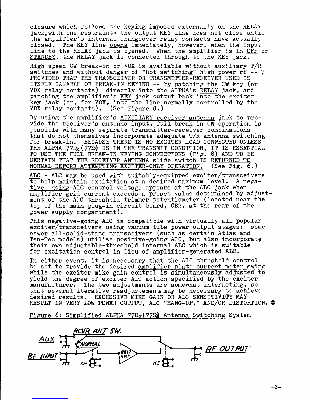
RECEIVER ANTENNA switch - Th is sli de switch M US T ^ BE IN THE THRU
POSITION for operation with conventional transceive-type connec
tio ns as described abo ve . In THR U, t t he antenna will b e fe d thru
to th e RF INP UT jac k whenever th e amplifier i s in OFF, STANDBY , o r
receive. permitting normal reception and exciter-only transm issio n.
In the SEPARATE p osit ion, th e antenna ( o r other load ) is connected
only to the AUXILIARY receiver antenna ja ck under these condit io ns.
THERE IS THEREFORE NO LOAD CONNECTED TO THE RF INPUT JACK AND
STRAIGHT-THROUGH EXCITER OPERATION IS NOT POSSIBLE. © ( S e e Fi g . 6 . )
AUXILIARY receiver antenna - As described abov e, this ja c k pro
vid es an alternate (a n d the onl y ) receiver antenna connection
when th e RECEIVER ANTENNA sl ide switch i s i n its SEPARATE posi
tio n and the amplifier i s in O FF , STAN DBY, OR recei ve.
KEY - Th is ("R C A " o r "pho no " ty pe ) ja ck may be used to.control
th e CW keyi ng , PTT , or other T/R function of the exciter while
insurin g proper sequencing of the T/R changeover switch ing. Th e
ALPHA 77Dx(an d 77$ 0 provides at this jac k an isolated contact
5 -
closure which follows the keying imposed externally on the RELAY
jack, with on e restraint: t he out put KEY line does not close unt il
th e amplifier's internal changeove r relay contact s have actually
cl os ed . The KEY line op en s imme diat ely, howeve r, when the inp ut
li ne t o the RELAY jac k is op en ed . When the amplifier is i n OFF or
STANDBY, t he RELAY ja ck i s connecte d through to the KEY j a c k .
High spee d CW break-in or VOX is available without auxiliary T/R
switche s and without danger of "h o t switching" high power rf - - ©
PROVIDED THAT THE TRANSCEIVER OR TRANSMITTER-RECEIVER USED IS
ITSELF CAPABLE OF BREAK-IN KEYING — by patching th e CW key ( o r
VOX relay contact s) directly into the ALPHA'S RELAY j a c k, and
patching the amplifier's KEY ja ck outpu t back into the exciter
key jac k (or, fo r VO X, in to the line normally controlled by th e
VOX relay co nta cts ). (Se e Figure 8. )
By using the amplifier's AUXILIARY receiver antenna j ac k to pro
vide th e receiver's antenna inpu t, full break-in CW operation is
possible with many separate transmitter-receiver combinations
that d o not themselves incorpora te adequate T/ R antenna switching
for break -in. BECAUSE THERE IS NO EXCITER LOAD CONNECTED UNLESS
THE ALPHA ? 7 Dx( 77S i $ IS IN THE TRANSMIT CONDITI ON, IT IS ESSENTIAL
TO USE THE FULL BREAK-IN KEYING CONNECTIONS (F i g. 8 ) AND TO BE
CERTAIN THA T THE RECEIVER ANTENNA slide switch I S RETURNED TO
NORMAL BEFORE ATTEMPTING EXCITER-ONLY OPERAT ION . ( S e e Fi g. 6 . )
ALC - ALC may be used with suitably-equipped exciter/transceivers
to help maintain excitation at a desired maximum le ve l. A nega
tiv e -going ALC control voltage appears at the ALC ja c k when
amplifier grid current exceeds a preset value determined by adjust
ment o f the ALC threshold trimmer potentiometer (loca ted near the
top of the main plug-in circuit boa rd , C B 2, at the rear of the
power supply compartm ent).
This negative-going ALC is compat ible with virtually all popular
exciter/transceivers using vacuum tube power output sta ges ; some
newer all-solid-state transceivers (su ch as certain Atlas and
Ten-Tec model s) utilize positive-going A LC, b ut also incorporate
their own adjustable-threshold internal ALC which i s suit able
for excitation control in lieu of amplifier-generated AL C.
In either ev en t, i t i s necessary that the ALC threshold contr ol
be se t t o provide the desired amplifier plate curre nt meter swing
while the exciter mike gain control is simultaneously adjusted t o
yield the degr ee o f exciter ALC action specified by the exciter
manufacturer. The two adjustments are somewhat interact ing, so
that several iterative read just emen ts may be necessary to achieve
desired result s. EXCESSIVE MIKE GAIN OR ALC SENSITIVITY MAY
RESULT IN VERY LOW POWER OUTPU T, ALC "HANG-UP," AND/OR DISTORTI ON. ©
Figure 6: Simplified ALPHA 77Dy(77 S^ Antenna Switching System
RCVR. A N T S M
-6-
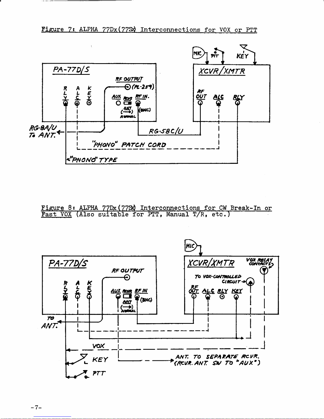
Fi g u re 7» ALP H A 77 D x (77Sd In t e r con n e c t i o n s for VO X or P T T
R G rS A /U
75 A N T .
R G -S8 C/U
|
__ _
<"PHOrJd' T Y P E
x c v r / x m t r
*F
OUT
Q
¿1C
I
I
+
¥
Figure 8»ALPHA 77Dx(7 7Sd Interconnections for CW Break-In or
Fast VOX (A l so suitable for PT T, Manual T/ R , etc .) ~
xcvr/x m t r
9
?
A LC RLY K£Y T
9
ro vox-a*rmou£j>
ctficutr**
vo x k s z a y
CONTACTS}
I
J
ANT. TO S£ P A X A T * R OVR.
(RCVX. A N T S V n *AUXm)
SECTION 3
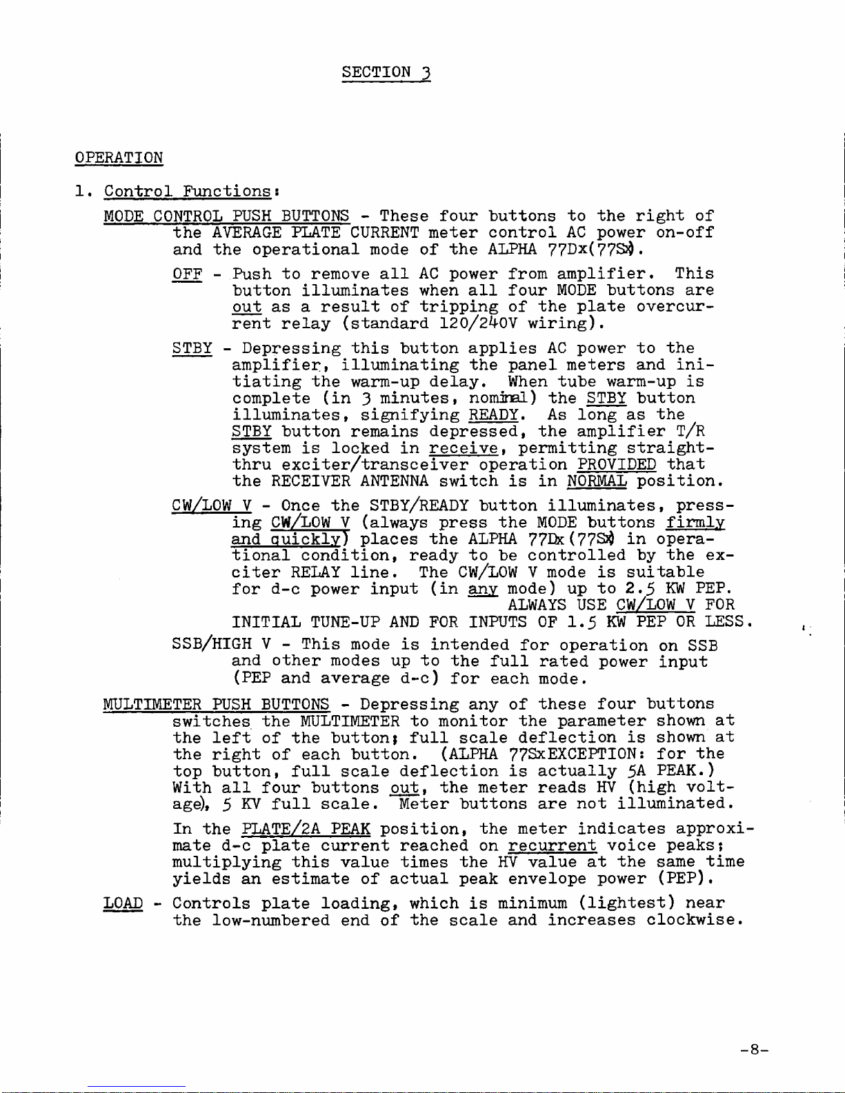
1 . Control Functions:
MODE CONTROL PUSH BUTTONS - Thes e four buttons to th e right o f
the AVERAGE PLATE CURRENT meter control AC power on-off
and the operational mode of the ALPHA 77Dx (7 7S$ .
OFF - Push to remove all AC power from amplifier . Thi s
button illuminates when all four MODE butto ns a re
out as a result of tripping of the plate overcur
rent relay (standa rd 120/240V wir ing ).
STBY - Depressing thi s button applies AC power to the
ampli fier » illuminating the panel meters and ini
tiating the warm-up del ay . When tube warm-up i s
complet e (i n 3 minut es, n o mina l ) th e STBY button
illum inate s, signifying READY. As long a s th e
STBY button remains dep ress ed, the amplifier T/R
system is locke d in rec eive , permitting straight-
thru exciter/transceiver operation PROVIDED that
the RECEIVER ANTENNA switch is i n NORMAL posit ion .
CW/LOW V - Once the STBY/READY button illuminat es, press
ing CW/LOW V (a l wa ys pres s the MODE buttons firmly
and quickly) pla ces the ALPHA 77Dx( 77S$ in opera
tional condi tion , ready to be controlled by th e ex
citer RELAY lin e. The CW/LOW V m ode is suitable
fo r d-c power input ( in any mod e) up to 2.5 KW P E P .
ALWAYS USE CW/LOW V FOR
INITIAL TUNE-UP AND FOR INPUTS OF 1.5 KW PEP OR LESS
SSB/HIGH V - This mode i s intended for operation o n SSB
and other modes up to th e full rated power input
(P E P and average d-c ) for each mo de.
MULTIMETER PUSH BUTTONS - Depressing any of these four butto ns
switche s th e MULTIMETER to monitor the parameter shown at
th e left of the but ton; full scale deflection i s shown at
th e right of each butt on. (AL PH A 77SxEXCEP TION: for th e
top button , full scale deflection is actually 5A PEA K.)
With all four buttons out, the meter reads HV (h ig h volt
age) , 5 KV full scal e. Meter buttons are not illu minat ed.
In th e PLATE/2A PEAK posit ion, the meter indica tes approxi
mate d- c plate current reached on recurrent voice peak s;
multiplying this value time s the HV value at the same time
yiel ds an esti mate of actual peak envelope power (PE P ) .
LOAD - Controls plate loadin g, which is minimum (l igh te st) near
th e low-numbered end of the sca le and increases clo ckw ise .
OPERATION

TUNE - Control s the plate tuning (v acu um vari able ) capac it or.
Capacitance is maximum ( lo we r frequency band s) at full
counterclockwise rotation and minimum (hi ghe r freq uenc y)
at full clockwise (s e e also paragraph 1, page 2).
Sele cts appropriate amplifier tuning rang e, a s indicated
( i n MHz ) on the dial skir t. Band "A " cover s 1.8 - 2.0 MHz;
Band "B" also covers 1.8-2.0 mHz and off ers additional loa din g.
Indi cate s onset of amplifier ALC action (" thr esh old ") when
grid current exceeds preset le ve l .
AVERAGE PLATE CURRENT - This meter indi cates averag e ( o r steady
state )d-c plate current as required for FCC-defined power
inpu t determinati on. On SSB/vo ice, average d-c power input
i s equ al to the highest indication of thi s meter as th e
pointer swings upward o n voice peaks multiplied by the HV
indication at the same ti m et (vo lt s) X (av er age amperes)=
(a ver ag e d-c power input in wat ts) . (EXCEPT ION FOR 77 S x
although meter scale indicates 1.0 amperes full scal e, an
interna l shunt in the ALPHA 77Sxmo difies this to 2.0 amps. )
2 . Tune-Up Procedure:
( a ) GENERAL - Serious amplifier damage and/or distortion may re
sult unless correct tune-up procedure i s followed.© Adequately-
heavy loading adjustment (f o r the drive leve l emplo yed ) is
particularly critical to avoid flattoppin g, flashov er, an d
possi ble tube damage. It is essential to be certain that all
system bandswitches are set for the same ban d , and that a
matched load for the frequency in use is connected before
applying excitat ion. It is equally essential that excessive
excitation (a n d grid curr ent ) be avoided at all time s during
tune-up and operatio n. An in-line monitoring oscilloscop e
i s highly recommended as the best means of cont inu ous , insta nt
visual monitoring of operating condition s. ©
( b) METER READINGS - All references in thi s manual , unless other
wise sp ecif ied, refer to operation with a steady carrier sig
nal ("key- down "). With a rapidly-varying SSB sig nal , actual
current and power level s ar e typically two to three times
greater than the values indicated by excur sions of the meter
pointers.
( c) ALPHA 77SxTUNE-UP AND METER INDICATIONS - Instruc tions given
herein apply basically to the ALPHA 77 0 ? where corresponding
values for th e ALPHA 77Scdiffer from those for th e 77 B & th e
" S " figu res ar e shown in parentheses fol lowi ng.
As previously noted, although the panels and meter scal es
are visually identical , th e ALPHA 77 S? cPLATE/2A PEAK MULTIMETER
button actually set s up a 5 ampere full scal e ra ng e, and th e
AVERAGE PLATE CURRENT meter actually indicate s ful l scale for
2 amper es plate cur rent , or on e ampere per tube.
BAND -
ALC -
-9 -
 Loading...