

EHRHORN Alpha 5841 User Manual

Ehrhorn Technotogical Operations, Inc.
4975 North 30th Street
Colorado Springs, CO 80919
OPERATING AND TECHNICAL MANUAL
HIGH FREQUENCY LINEAR POWER AMPLIFIERS
MODELS PA-76, PA-76P, and PA-76C
EHRHORN TECHNOLOGICAL OPERATIONS, INC.
Revised May 1, 1977
TABLE OF CONTENTS
SECTION 1
SECTION 2
SECTION 3
SECTION k -
SECTION 5 -
SECTION 6 -
ET0/"A LP H A"
- General Description and Specifications
■ INSTALLATIO N
High Vol tage Tap Selection
...............
3
Inter con nect ion s With Other Equipment . . . 4
• OPERATION
5
Init ia l Tune-Up
........................
6
Operat ion At 1 KW and 2 KW Input
....... ..
7
ALPHA 76 P and ALPHA 7&C Operating Differenc es 8
Operating No t es
........................
9
Troubleshooting Hi nts
..................
1 0
THEORY OF O P E R ATION
....................
1 1
ILLUSTRATIONS
..........................
1 3
Transformer Installation or Removal . . . . 1 3
Rear V i e w
.............................. 1 3
To p View Sh owing Major Compon ent Locations . 1 4
Sche ma tic Diagram
......................
15
Fron t Panel V ie w
...............
Front Cove r
STANDAR D ELECTRICAL PARTS
...............
1 6
PRODU CTS WARRANTY
...............
Back Cove r
EHRHORN TECHNOLOGICAL OPE RA TI ON S, INC .
CANON CI T Y , COLO RA DO 812 1 2
5/7 7 U. S. A .
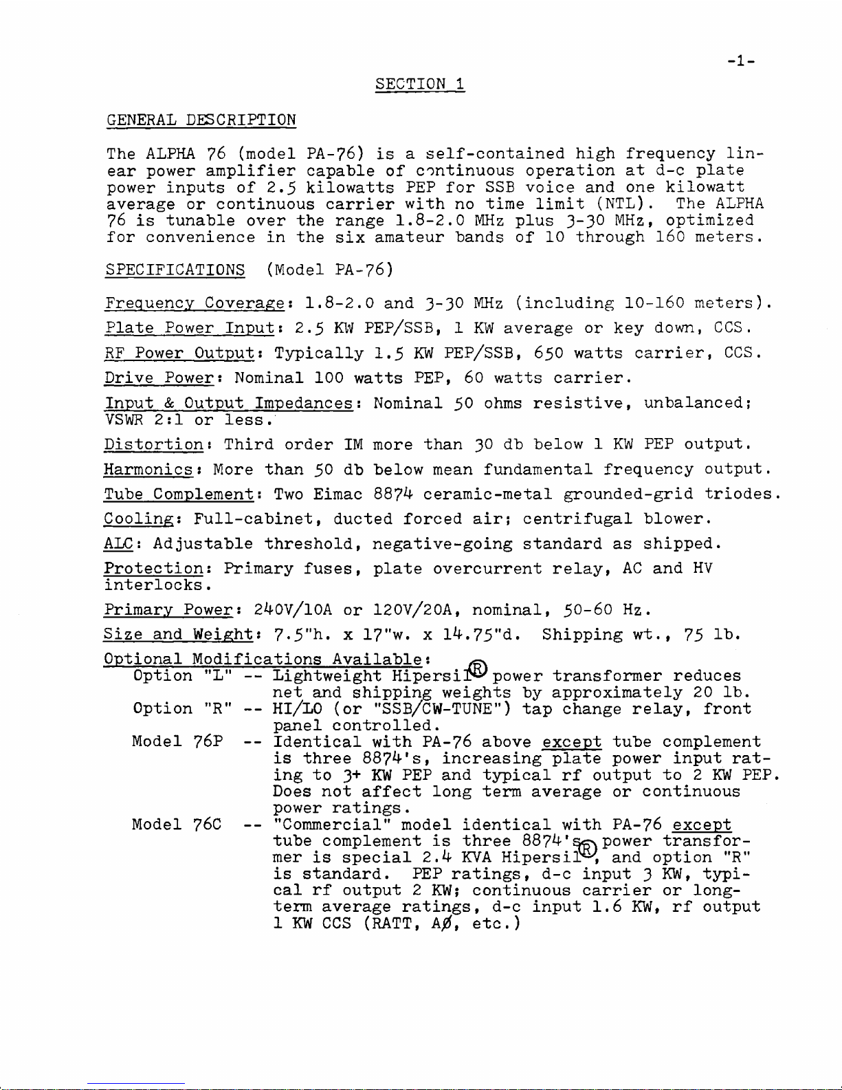
Th e ALPHA 7 6 (mo d el P A- 7 6 ) is a self-conta ined hig h frequency lin
ea r power amplifier capa bl e of cont inu ous operation at d-c pla te
powe r in pu t s of 2. 5 kilow att s PEP fo r SSB voice and one kilo wat t
aver ag e or conti nuou s carrie r with no time limit (NTL). Th e AL PH A
7 6 i s tunable ov er t h e ran ge 1. 8-2 .0 MH z plus 3_3 ° MH z , optim ize d
fo r convenien ce in t h e six amate ur bands of 1 0 through 16 0 met e r s.
SPECIFICA TIONS ( M od e l PA-7 6)
Frequen cy Coverage: 1.8- 2. 0 and 3-3 0 MHz (inclu din g 10-16 0 met er s ).
Pl at e Power Input; 2.5 KW PEP/ S SB , 1 KW avera ge or key do w n , CCS.
RF Power Output: Typically 1.5 KW PE P/ S SB , 650 watts ca r ri e r, C CS .
Dri ve Powers Nominal 100 wa tts P E P , 60 watt s ca r ri er .
In pu t & Output Impedances; Nominal 50 oh m s resi st ive , unb al an ce d;
VS WR 2: 1 or l e s s .
Distortion: Third ord er IM more than 30 3b below 1 KW PEP ou t p u t .
Harmon ics : More than 50 db below mean fundament al frequency ou t put .
Tu be Complement; Two Eim ac 88?^ ceramic-meta l grounded-grid triodes.
Cooling: Full-ca bin et , duct ed forced a i r ; centrifugal bl ow e r.
ALC: Adjustable thre sh ol d , negative-going standa rd as sh i pp e d.
Protection: Primary fus e s , plate overcurrent rela y , AC and HV
interlocks.
Primar y Power: 24QV/ 10A or 12 0V / 20 A, nom in al , 50-60 Hz.
Si ze and Weight: 7.5 "h. x 17" w . x l4 .7 5 " d. Shipping wt . , 75 lb .
Opti ona l Modifications Available:
Lightweig ht Hipersir^ power transformer re du ce s
net and shippin g weight s by approximately 20 l b.
HI/LO (o r "SSB/CW-TUNE”) tap chang e relay , fro n t
pane l cont ro ll ed .
Iden tic al with PA-7 6 abov e except tub e compl eme nt
i s th re e 8874's, increasing plate power inp ut rat
ing t o 3+ KW PEP and typical rf output to 2 KW PEP.
Do es not affect long term average or cont in uou s
power ratings.
"Co mm er ci al " model identic al with PA- 7 6 ex ce p t
tub e compl ement is thre e 8874' power transfor
mer is special 2.4 KVA Hipe rsi r^ , and option "R "
i s st a nd ar d . PEP rat in gs , d-c input 3 K W , typi
ca l rf out pu t 2 K W ; continuou s carrier or long
term avera ge ratin gs , d-c input 1.6 KW , rf ou t pu t
1 KW CC S (RATT, A0, etc . )
-1-
SECTION 1
GENERAL DE SCRIPTION
Opti on "L" --
Option " R" - -
Model 76? --
Model 76C - -
2-
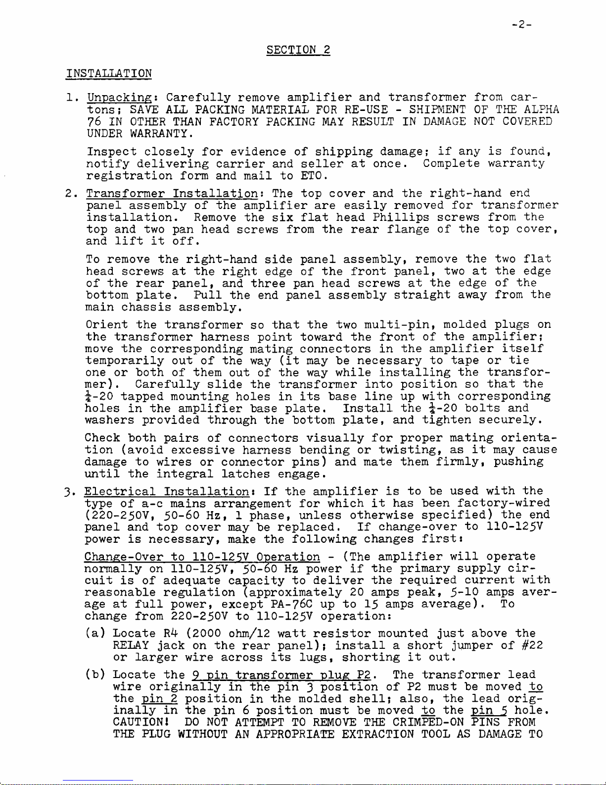
Unpacking: Carefully re mo v e amplifier and transfo rmer from car
to n s; SAVE ALL PACKING MATE RIAL FO R RE-USE - SHIPME NT OF THE ALP HA
7 6 I N OTHER THAN FACTO RY PACK ING MAY RESULT IN DAM AGE NO T COVER ED
UNDER WAR RA N TY .
Insp ec t closel y for ev i de nc e of shipping da m a ge ; if any i s fo u n d ,
notify delivering carr ie r and selle r at on ce. Comp le te warranty
registration form and ma il to ET O.
2. Transformer Installation; Th e top cover and th e right-hand end
pane l assembly of the amplifier a re easily removed for transforme r
ins tal la ti on . Rem ov e th e si x fla t head Philli ps scre ws from th e
top and two pan head scr e ws from the rear fla ng e of the top c o v e r ,
and li ft it o f f .
To remove th e right-hand sid e panel as se mb ly, remov e the two fl a t
hea d scre ws at the right ed g e of the fron t pa n e l , tw o at the edge
of th e rear pan el , and thre e pan head scre ws at the edg e of th e
bottom pl at e . Pull th e en d panel assembly strai ght away fro m th e
main cha ssi s ass em bl y .
Ori e nt the transformer so tha t the two multi- pin , molded pl ug s o n
th e transformer harn es s poi n t towar d th e fron t of the am pli fi er ;
move the corre sponding mating con necto rs in the amplifier itse lf
temporarily out of th e way ( it may be necessary to ta pe o r ti e
one or both o f them ou t of th e way while insta lling th e transfor
me r) . Carefully slid e th e transformer in t o positi on s o that t h e
i-20 tapped mounting hol e s in it s base line up with corresponding
hol es in the ampli fier ba s e pl a t e. Install the J-20 bol ts an d
washe rs provided through th e bottom pla t e, and tig hte n se cu r el y.
Check both pai r s of con ne ct or s visually for prope r mating orienta
tion (av oi d exces siv e ha rn e ss bending or tw is ti n g, as it may cau se
dama ge to wir es or conne ct or pi n s ) and mate them fir ml y , pushing
until th e integral lat c h es eng a g e .
3» Electrica l Installation: If th e amplifier is to be used with the
ty pe of a- c mains arran gem ent for which it has been factory-wired
(2 2 0- 2 5 0V , 50-60 Hz , 1 ph a se , unl ess otherw ise specif ied ) th e en d
panel an d top cover may b e repla ce d . I f change-ov er to 110 -12 5V
power i s necessa ry, mak e th e following change s fi r s t :
Change-Over to 110-125 V Opera tio n - (The amplifier will ope ra te
normally on 110- 12 5V , 50 -6 0 Hz power i f the primary supply cir
cu it i s of adequate capac ity to deliver the required current wit h
reason able regulation (app rox ima tel y 2 0 amps pea k , 5-10 amp s aver
age at full pow er , exce p t PA-76C up to 15 amps av er ag e ). To
cha ng e from 220-250V to 110 -1 25V ope ra ti on:
(a ) Locate R4 (2 0 0 0 oh m /1 2 wat t resistor mounted jus t above th e
RELAY jac k on the rear panel); install a short jump e r of #2 2
or large r wir e ac ro s s it s lu g s , shorting i t o ut.
( b) Locate the 9 pin transfo rmer plug P2. The transformer lea d
wire originally in th e pin 3 position of P2 must be moved tc>
the pin 2 position in t he molded she ll ? al s o , the lead orig
inally in the pin 6 positio n must b e moved t o th e pin 5 hol e .
CA UT IO N ! DO NOT ATTEM PT TO REMOVE THE CRIMPED-O N PINS FRO M
THE PLUG WITHOUT AN APPROPRIATE EXTRACTION TOOL A S DAMAGE TO
SECTI ON 2
INSTALL ATION
I
3
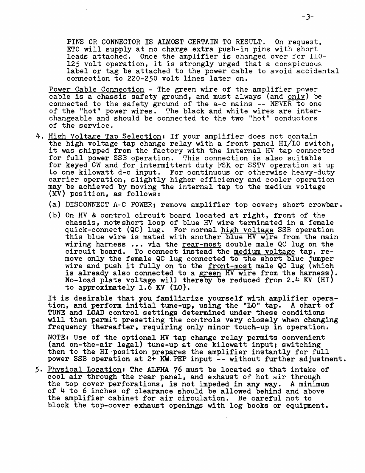
PIN S OR CONNECTOR I S AIMOST CERTAIN TO RES UL T . On re q u es t ,
ETO will supply a t no char ge extra push-in pi ns with sh or t
le ad s attac he d. On ce the amplif ier i s changed over for 1 10 -
125 volt ope ra t io n, it i s strongly urged that a consp icu ous
label or tag be attached t o the power cable to avoid accid ental
connection to 220-250 volt li n e s later o n.
Power Cable Connectio n - The green wire of the amplifier power
cab le is a chass is safety grou n d, and must always (a n d only) b e
connect ed to th e safety ground of the a- c mains -- NEVER to one
of the "h o t " pow er wi re s . Th e black and white wires are inter
chang eab le and should be connect ed to th e two "ho t " conduc to rs
of the servi ce .
4. High Voltage Tap Selection: If your amplifier doe s not contain
th e high voltage tap cha nge relay with a fron t panel Hl/LO sw i t c h ,
i t was shipped from t he factory with the internal HV tap conn ec ted
for ful l power SSB ope ra ti on . Thi s connection is also suita bl e
for keyed CW and for intermittent duty FSK or SSTV opera tion at up
to on e kilowatt d-c inp u t . For cont inu ous or otherwise heavy-dut y
carrie r ope ra ti on , slightly higher efficiency and cooler operati on
may be achieved by moving the internal ta p t o the medium voltag e
( M V) positi on , a s fol lo ws :
( a) DISCONNECT A-C PO WE R ; remove amplifier top cove r ; short cro wb ar .
( b) On HV & contro l circuit board located at right, front of th e
chassis, no te shor t loop of b lu e HV wire terminated in a fema le
quick-connect ( QC ) lug. For normal high voltage SSB operat ion
thi s blu e wire i s mated with another blue HV wire from t h e main
wiring harn ess . .• via the rear- most doub le male QC lug on th e
circui t boar d . To connect instead the medium voltage tap, re
move only t he fem al e QC lug connected to the short blue ju mp e r
wire and push it fully on to t h e front-most male QC lug (w hi c h
is already als o connected t o a green HV wire from the har ne s s) .
No-load plate voltage will thereby be reduced from 2.4 KV (HI )
to approximately 1. 6 KV (LO ) .
It is desirable that you famili arize yourself with amplifier opera
ti o n, and perform initia l tune -u p , using the "LO ” ta p . A ch ar t of
TUNE and LOAD control settings determine d under these con dit ion s
will then permit presetting the con tro ls very closely when changing
frequency therea fte r, requiring only minor touch-up in ope ra ti o n.
NO T E* Use of th e optional HV tap change relay permits conve nien t
(a n d on-the-ai r lega l) tune-up at one kilowatt inp ut ; switching
then to the HI position prepare s the amplifier instantly fo r full
power SSB operation at 2+ K W. PEP inp ut -- without further adj ust me nt .
5* Physical Locationt The ALPHA 7 6 mu st be located so that int ak e of
cool air through the rear pane l, and exhaust of hot air thro ugh
the top cover perfor ation s, is not impe ded in any wa y . A minimum
of 4 to 6 inche s of clearance should be allowed behind and ab o v e
the amplifier cabinet for air cir cu lat ion . Be careful not t o
block the top-cover exha ust ope ni ng s with log boo ks or equ i pm en t .
4
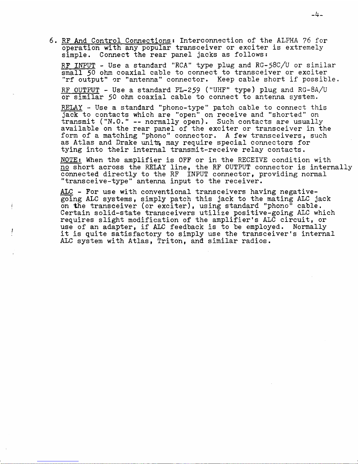
6. RF And Control Conne ct io ns : Interconnection of th e ALPHA 76 for
operati on with any pop ular transceiver o r exci ter i s extr eme ly
si m pl e . Connect th e rear panel j ac k s a s foll o ws :
RF INPU T - Use a stand ar d "RCA " type plug an d RG-58C/U or simil ar
smal l 50 ohm coaxia l cabl e to connec t to transceive r or exci te r
" r f output” o r ’’anten n a" conne ct or . Keep cab le short i f po s si b l e.
RF OUTPUT - Use a standar d PL-259 ("U H F " typ e ) plug and RG-8A/U
or similar 50 ohm coax ia l cabl e to connec t t o antenna sy s t e m .
RELAY - Use a standa rd "phon o-t yp e" patch cab le to connect t h i s
ja c k to contact s whi ch are "ope n " on receive and "sh ort ed " on
transmi t ("N .O . " - - normally ope n) . Such contacts are usually
availab le o n t he re ar panel of the exc iter or transceiver i n th e
form of a matching "p h o n o " conn ec to r. A few tran scei vers , su ch
as Atlas and Drake uni*t^ may require special connectors for
tying into their in te rn al transmit-receive relay conta ct s.
NOTE: When th e amplifier is OF F or in th e RECEIVE condition with
no short across th e RELAY li n e , the RF OUTPU T connector i s internally
connected directly to the RF INP UT conn ec to r, providing norm al
"tran scei ve-ty pe" ante nn a in pu t to th e recei ve r.
ALC - For use with conve ntio nal transceivers having negative-
going A LC syst em s, simpl y patch thi s jac k to the mating ALC ja c k
on th e transceiver (or exc i te r ), using standard "phono” ca b l e .
Certain solid-sta te transcei ver s utilize positive-going AL C which
requi res slight modification of the amplifier 's ALC cir c ui t , or
us e o f an adap te r, if A LC feedback i s to be em pl oy ed . Normally
it is quite satisfactory t o simply us e the transceiver's inter nal
ALC system with At l a s, Tr it o n, and similar rad io s.
 Loading...