

Ehong EH-MB18 User Manual
•
Bluetooth radio
-
Fully embedded Bluetooth® v4.2(Smart ready)
-
Bluetooth® v3.0 specification compliant
-
TX power +8dbm,-90dbm RX sensitivity
-
128-bit encryption security
-
Range up to 15m
-
Internal chip antenna or U.fl port
-
Multipoint capability(7 transmit data devices
connected at the same time)
•
Support profiles
-
SPP (Master and slave), iAP (ipod accessory
protocol)
-
BLE(GATT Profile)
-
HFP ,A2DP,AVRCP,HID(Salve)
•
User interface
- Send AT command over UART
- Firmware upgrade over USB
- With SPP service active: 560kbps transmission
speed (UART)
- PCM interface (I2S,SPDIF)
- I2C interface(Master ),SPI
•
Audio codec
- optional support for 64Mb of external SPI flash
16Mb internal flash memory (64-bit wide, 45ns)
-
80MHz RISC MCU and 80MIPS Kalimba DSP
- Support for CSR's latest CVC technology for
narrow-band and wideband voice connections
including wind noise reduction
-
Support Apt-X ,AAC, Apt-XLL,SBC codec
•
General
I/O
-
13 eneral purpose I/Os
-
2 analogue I/O
-
Support for up to 3 capacitive touch sensor
inputs
-
Three fully configurable LED drivers
•
FCC and Bluetooth® qualified
•
Single voltage supply: 2.7-3.6V
•
Small form factor: 30.4 x 15.26 x 2.4mm
•
Operating temperature range: -40 °C to 85 °C
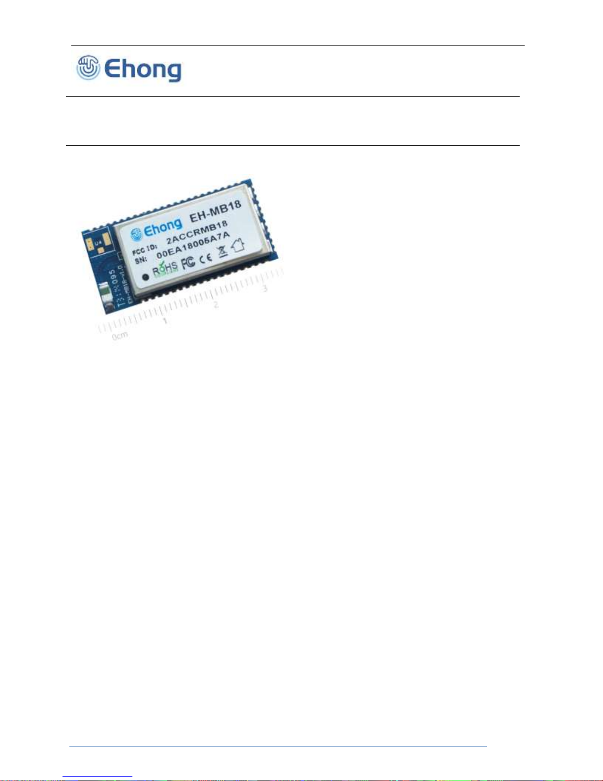
EH-MB18
Bluetooth® Technology
Audio
Module
Ehong Technology Co., Ltd

Bluetooth Audio Module
1. Contents
1. Description ......................................................................................................................................................... 4
2. Application ......................................................................................................................................................... 4
3. EH-MB18 Product numbering ........................................................................................................................ 4
4. Electrical Characteristic .................................................................................................................................. 5
4.1. Recommend operation conditions ............................................................................................................ 5
4.2. Absolute Maximum Rating ......................................................................................................................... 5
4.3. Power consumptions .................................................................................................................................. 5
4.4. Input/output Terminal Characteristics ...................................................................................................... 7
4.4.1. Digital Terminals .................................................................................................................................. 7
4.4.2. USB ....................................................................................................................................................... 8
4.4.3. Internal CODEC Analogue to Digital Converter ................................ .............................................. 8
4.4.4. Internal CODEC Digital to Analogue Converter.............................................................................. 9
5. Pinout and Terminal Description ................................................................................................................ 10
5.1. Pin assignment .......................................................................................................................................... 10
6. Physical Interfaces ......................................................................................................................................... 13
6.1. Power Supply ............................................................................................................................................. 13
6.2. Reset ........................................................................................................................................................... 13
6.3. PIO .............................................................................................................................................................. 14
6.4. AIO .............................................................................................................................................................. 14
6.5. RF interface ............................................................................................................................................... 14
6.6. UART .......................................................................................................................................................... 14
6.7. I2C Master .................................................................................................................................................. 15
6.8. Apple iOS CP reference design .............................................................................................................. 16
6.9. Digital Audio Interfaces ............................................................................................................................ 17
6.9.1. PCM .................................................................................................................................................... 18
6.9.2. Digital Audio Interface (I2S) ............................................................................................................. 19
6.9.3. IEC 60958 Interface (SPDIF) .......................................................................................................... 22
6.10. Microphone input ................................................................................................................................... 23
6.11. Analog Output stage ............................................................................................................................. 24
6.12. USB ......................................................................................................................................................... 24
7. EH-MB18 Reference Design ......................................................................................................................... 26
Ehong Technology Co., Ltd

Bluetooth Audio Module
8. Mechanical and PCB Footprint Characteristics ...................................................................................... 27
9. RF Layout Guidelines .................................................................................................................................... 28
10. Reflow Profile ............................................................................................................................................... 29
11. Contact Information ................................................................................................................................... 30
2. Table of Tables
TABLE 1: RECOMMENDED OPERATING CONDITIONS .................................................................................................... 5
TABLE 2: ABSOLUTE MAXIMUM RATING RECOMMENDED OPERATING CONDITIONS ................................................... 5
TABLE 3: POWER CONSUMPTIONS ................................................................................................................................ 7
TABLE 4: DIGITAL TERMINAL ......................................................................................................................................... 8
TABLE 5: USB TERMINAL .............................................................................................................................................. 8
TABLE 6: ANALOGUE TO DIGITAL CONVERTER ............................................................................................................. 9
TABLE 7: DIGITAL TO ANALOGUE CONVERTER ........................................................................................................... 10
TABLE 8:PIN
TABLE 9: PIN STATUS ON RESET ................................................................................................................................ 14
TABLE 10: POSSIBLE UART SETTINGS ...................................................................................................................... 15
TABLE 11: ALTERNATIVE FUNCTIONS OF THE DIGITAL AUDIO BUS INTERFACE ON THE PCM INTERFACE ............... 18
TABLE 12 : DIGITAL AUDIO INTERFACE SLAVE TIMING ............................................................................................... 21
TABLE 13 : DIGITAL AUDIO INTERFACE MASTER TIMING............................................................................................ 21
TABLE 14: USB INTERFACE COMPONENT VALUES .................................................................................................... 25
TERMINAL DESCRIPTION
................................ ................................................................ ..................... 13
3. Table of Figures
FIGURE 1:PINOUT OF EH-MB18.............................................................................................................................. 10
FIGURE 2:POWER SUPPLY PCB DESIGN ................................................................................................................ 13
FIGURE 3:CONNECTION TO HOST DEVICE ............................................................................................................... 15
FIGURE 4 : EXAMPLE EEPROM CONNECTION WITH I2C INTERFACE ........................................................................ 16
FIGURE 5 : APPLE CO-PROCESSOR 2.0C ................................................................................................................... 16
FIGURE 6 : APPLE CO-PROCESSOR 2.0B ................................................................................................................... 17
FIGURE 7 : AUDIO INTERFACE ..................................................................................................................................... 18
FIGURE 8 : DIGITAL AUDIO INTERFACE MODES .......................................................................................................... 20
FIGURE 9 : DIGITAL AUDIO INTERFACE SLAVE TIMING ............................................................................................... 21
FIGURE 10 : DIGITAL AUDIO INTERFACE MASTER TIMING .......................................................................................... 21
FIGURE 11
FIGURE 12: EXAMPLE CIRCUIT FOR SPDIF INTERFACE (OPTICAL) ........................................................................... 22
FIGURE 13: MICROPHONE BIASING (SINGLE CHANNEL
FIGURE 14: SPEAKER OUTPUT .................................................................................................................................... 24
FIGURE 15: USB CONNECTIONS ................................................................ ................................ ................................ 25
FIGURE 16: REFERENCE DESIGN ............................................................................................................................... 26
FIGURE 17: RECOMMENDED PCB MOUNTING PATTERN (UNIT: MM, DEVIATION:0.02MM)TOP VIEW ..................... 27
FIGURE 18: CLEARANCE AREA OF ANTENNA ............................................................................................................. 28
FIGURE 19: RECOMMENDED REFLOW PROFILE ......................................................................................................... 29
Ehong Technology Co., Ltd
: EXAMPLE CIRCUIT FOR SPDIF INTERFACE (CO-AXIAL)
S
HOWN
........................................................................ 22
)
............................................................................... 23

Bluetooth Audio Module
1. Description
The EH-MB18 is an easy to use Bluetooth module, compliant with Bluetooth v4.2. The module
provides complete RF platform in a small form factor.
The module enables electronic devices with wireless connectivity, not requiring any RF
experience or expertise for integration into the final product. The module being a certified
solution optimizes the time to market of the final application.
The module built-in enhanced Kalimba DSP coprocessor with 80MIPS, supports enhanced
audio and DSP Applications (t Apt-X, AAC, Apt-XLL, SBC codec).Support GATT,A2DP, AVRCP,
HSP, HFP,SPP, iAP and PBAP Profiles communication with smart ready devices.
The module BLE profile communication with smart phones (iOS and Android), must be install
the APP. EHong iOS system APP download address: https://itunes.apple.com/cn/app/ehong-
link/id854886208?mt=8.
The module has 14 x general purpose IOs, 2x Analogue inputs/outputs (temperature sensor,
charger control, etc), 3xs capacitive touch sensors, three fully configurable LED drivers
(PWM).The module optional support for 64Mb of external SPI flash 16Mb internal flash memory
(64-bit wide, 45ns),support Li-Ion battery charger with Instant-ON.
2. Application
Home entertainment eco-system
TVs
Smart remote controllers
Wired or wireless sound bars
Wired or wireless speakers and headphones
Bluetooth low energy connectivity to external 3D glasses
Tablets / PCs / Mobile Connectivity
Wired or wireless headphones for music / gaming / multimedia content
Wired or wireless speakers
Wired or wireless speaker phones
Mono Headsets for voice
3. EH-MB18 Product numbering
EH-MB18(B)
A. EH ------------- Company Name(Ehong)
B. MB18 ------------ Module Name
C. B ------------- U.FL Connector
Ehong Technology Co., Ltd
Bluetooth Audio Module
Operating Condition
Min
Typical
Max
Unit
Operating Temperature Range
-40
--
+85
°C
PIO Voltage
+1.7
+3.3
+3.6
V
AIO Voltage
+1.7
+1.8
+1.95
V
LED
+1.1
3.7
+3.6
V
VDD Voltage
+2.7
+3.3
+3.6
V
VCHG(a)
+4.75
+5
+5.75
V
RF frequency
2400
2441
24800
MHz
DUT Role
Connection
Packet Type
Average
Current
Unit
N/A
Deep
sleep
With UART host
connection
- 55
uA
N/A
Page
scan
Page = 1280ms
interval
Window = 11.25ms
-
219
uA
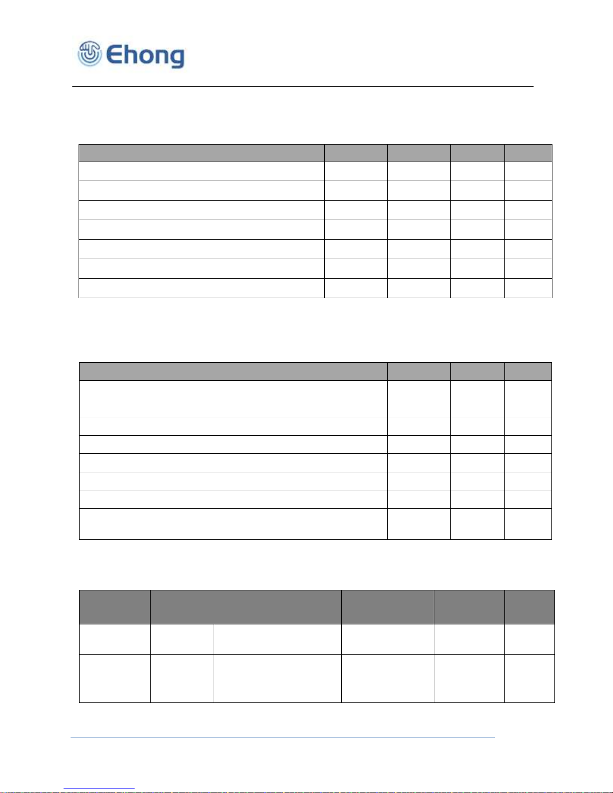
4. Electrical Characteristic
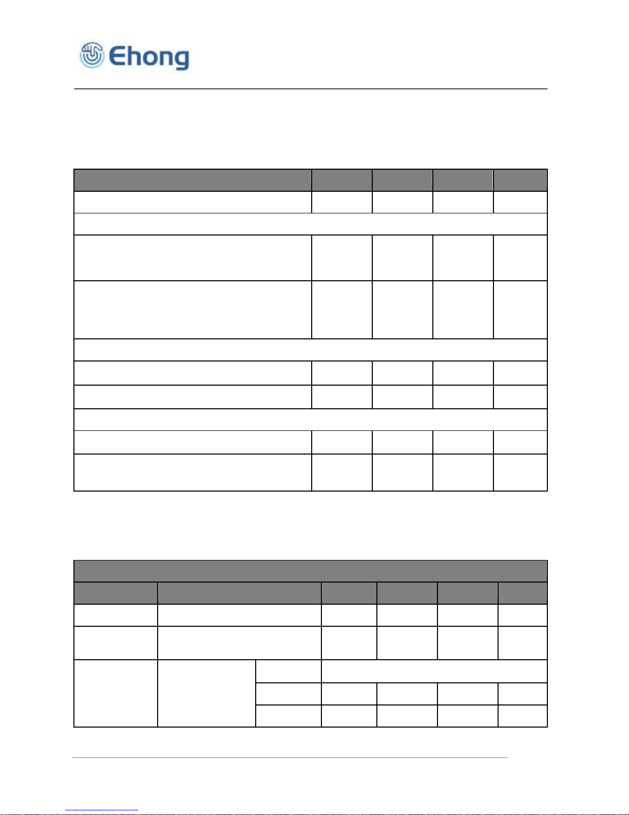
4.1. Recommend operation conditions
Table 1: Recommended Operating Conditions
Note:(a) Maximum charging current 200mA
4.2. Absolute Maximum Rating
Rating Min Max Unit
Storage Temperature -40 +125 °C
PIO Voltage -0.4 +3.6 V
AIO Voltage -0.4 +1.95 V
LED -0.4 +3.6 V
VDD Voltage -0.4 +3.6 V
VCHG -0.4 +5.75 V
USB_DP/USB_DN Voltage -0.4 +3.6 V
Other Terminal Voltages VSS-0.4
Table 2: Absolute Maximum Rating Recommended Operating Conditions
VDD+0.
4
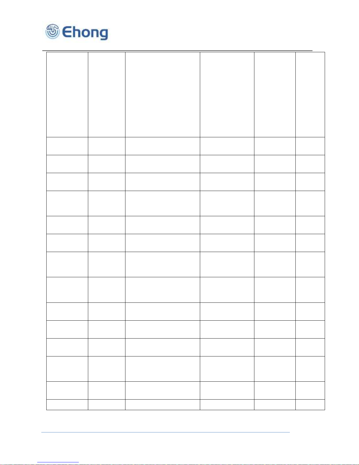
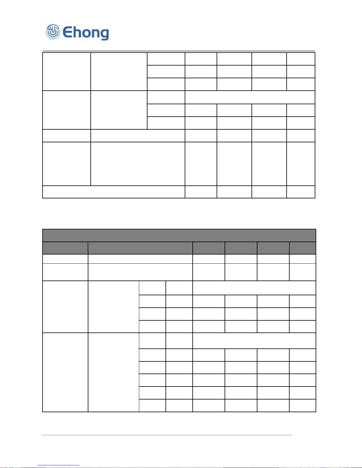
4.3. Power consumptions
V
Ehong Technology Co., Ltd
Bluetooth Audio Module
N/A
Inquiry
a n d
p a g e
sca n
Inquiry
=
1280m
s
interval
Page =
1280m
s
interval
Windo
w =
11.25m
s
-
378
uA
Master
ACL
Sniff = 500ms, 1
attempt, 0 timeout
DH1
119
uA Master
ACL
DH1
109
uA
Master
SCO
HV3
7.6
mA
Master
SCO
HV3
9.8
mA
Master
eSCO
2EV3
5.8
mA Master
eSCO
Setting S3, sniff =
100ms, PCM
3EV3
5.4
mA
Master
eSCO
Setting S3, sniff =
100ms, mono audio
codec
2EV3
7.9
mA Master
eSCO
Setting S3, sniff =
100ms, mono audio
codec
3EV3
7.5
mA
Slave
ACL
Sniff = 500ms, 1
attempt, 0 timeout
DH1
127
uA
Slave
ACL
Sniff = 1280ms, 8
attempts, 1 timeout
DH1
129
uA
Slave
SCO
Sniff = 100ms, 1
attempt, PCM
HV3
7.8
mA
Slave
SCO
Sniff = 100ms, 1
attempt, mono audio
codec
HV3 10
mA
Slave
eSCO
Setting S3, sniff =
100ms, PCM
2EV3
6.2
mA
Slave
eSCO
Setting S3, sniff =
3EV3
5.8
mA
Sniff = 1280ms, 8
attempts, 1 timeout
Sniff = 100ms, 1
attempt, PCM
Sniff = 100ms, 1
attempt, mono audio
codec
Ehong Technology Co., Ltd
Setting S3, sniff =
100ms, PCM
Bluetooth Audio Module
100ms, PCM
Slave
eSCO
Setting S3, sniff =
100ms, mono audio
codec
2EV3
8.2
mA Slave
eSCO
Setting S3, sniff =
100ms, mono audio
codec
3EV3
7.9
mA
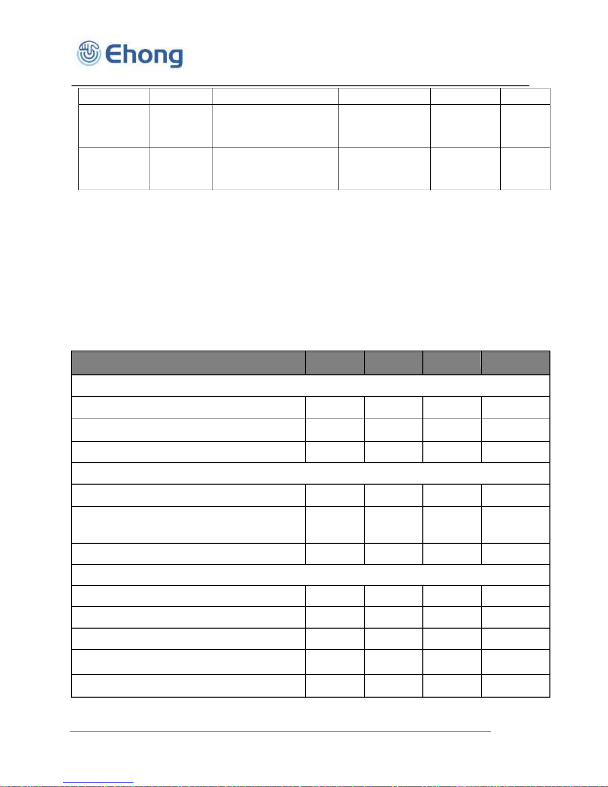
Digital Terminals
Min
Type
Max Unit
Input Voltage
V
IL
input logic level low
--
0.4 V
V
IH
input logic level high
0.7 x VDD
-
VDD + 0.4
V
Tr/Tf - - 25 ns
Output Voltage
V
OL
output logic level low, l
OL
= 4.0mA
- - 0.4 V
V
OH
output logic level high, l
OH
= -4.0mA
0.75 X
VDD
- - V
Tr/Tf - - 5 ns
Input and Tristate Currents
Strong pull-up
-150 -40 -10
μA
Strong pull-down
10 40
150
μA
Weak pull-up
-5
-1.0
-0.33
μA
Weak pull-down
0.33 1.0 5.0
μA
CI Input Capacitance
1.0 - 5.0 pF
Table 3: Power consumptions
Note :
Current consumption values are taken with:
■
Firmware ID = 7919
■
RF TX power set to 0dBm
■
No RF retransmissions in case of eSCO
■
Audio gateway transmits silence when SCO/eSCO channel is open
■
LEDs disconnected
■
AFH off
4.4. Input/output Terminal Characteristics
4.4.1. Digital Terminals
Ehong Technology Co., Ltd
Min
Type Max
Unit
VDD_USB for correct USB operation
3.10
3.30
3.60 V
Input Threshold
V
IL
input logic level low
-
-
0.30 x
VDD_US
B
V
V
IH
input logic level high
0.70 x
VDD_US
B
-
-
V
Input Leakage Current
VSS_DIG < V
IN
< VDD_USB
(a)
-1 1 5 µA
CI input capacitance
2.5 - 10 pF
Output Voltage Levels to Correctly Terminated USB Cable
V
OL
output logic level low
0 - 0.2 V
V
OH
output logic level high
2.80 -
VDD_USB
V
Analogue to Digital Converter
Parameter
Conditions
Min
Type
Max
Unit
Resolution
- - - 16
Bits
Input Sample
Rate, Fsample
-
8
-
48
kHz
f
in
= 1kHz
B/W =
20Hz→F
sample
/
F
sample
8kHz - 93 - dB
16kHz
- 92 - dB
4.4.2. USB
Bluetooth Audio Module
Table 4: Digital Terminal
Table 5: USB Terminal
(a) Internal USB pull-up disable
4.4.3. Internal CODEC Analogue to Digital Converter
Ehong Technology Co., Ltd
Bluetooth Audio Module
SNR
2 (20kHz max)
A-Weighted
THD+N < 0.1%
1.6V
pk-pk
input
32kHz
- 92 - dB 44.1kHz
- 92 - dB 48kHz
- 92 - dB
THD+N
f
in
= 1kHz
B/W =
20Hz→F
sample
/
2 (20kHz max)
1.6V
pk-pk
input
F
sample
8kHz - 0.004 - %
48kHz
- 0.008 - %
Digital gain
Digital gain resolution = 1/32
-24 -
21.5 dB
Analogue gain
Pre-amplifier setting = 0dB,
9dB, 21dB or
30dB
Analogue setting = -3dB to
12dB in 3dB
steps
-
3
-
42
dB
Stereo separation (crosstalk)
- -89 - dB
Digital to Analogue Converter
Parameter
Conditions
Min
Type
Max
Unit
Resolution
- - - 16
Bit
Output Sample
Rate, F
sample
-
8
-
96
kHz
SNR
f
in
= 1kHz
B/W =
20Hz→20kHz
A-Weighted
THD+N < 0.01%
0dBFS input
F
sample
Load
48kHz
100kΩ - 96 - dB
48kHz
32Ω - 96 - dB
48kHz
16Ω - 96 - dB
THD+N
f
in
= 1kHz
B/W =
20Hz→20kHz
0dBFS input
F
sample
Load
8kHz
100kΩ -
0.002 - %
8kHz
32Ω -
0.002 - %
8kHz
16Ω -
0.003 - %
48kHz
100kΩ -
0.003 - %
48kHz
32Ω -
0.003 - %
Table 6: Analogue to Digital Converter
4.4.4. Internal CODEC Digital to Analogue Converter
Ehong Technology Co., Ltd
Bluetooth Audio Module
48kHz
16Ω -
0.004 - %
Digital Gain
Digital Gain Resolution = 1/32
-24 - 21.5 dB
Analogue Gain
Analogue Gain Resolution = 3dB
-21 - 0 dB
Stereo separation (crosstalk)
- -88 - dB
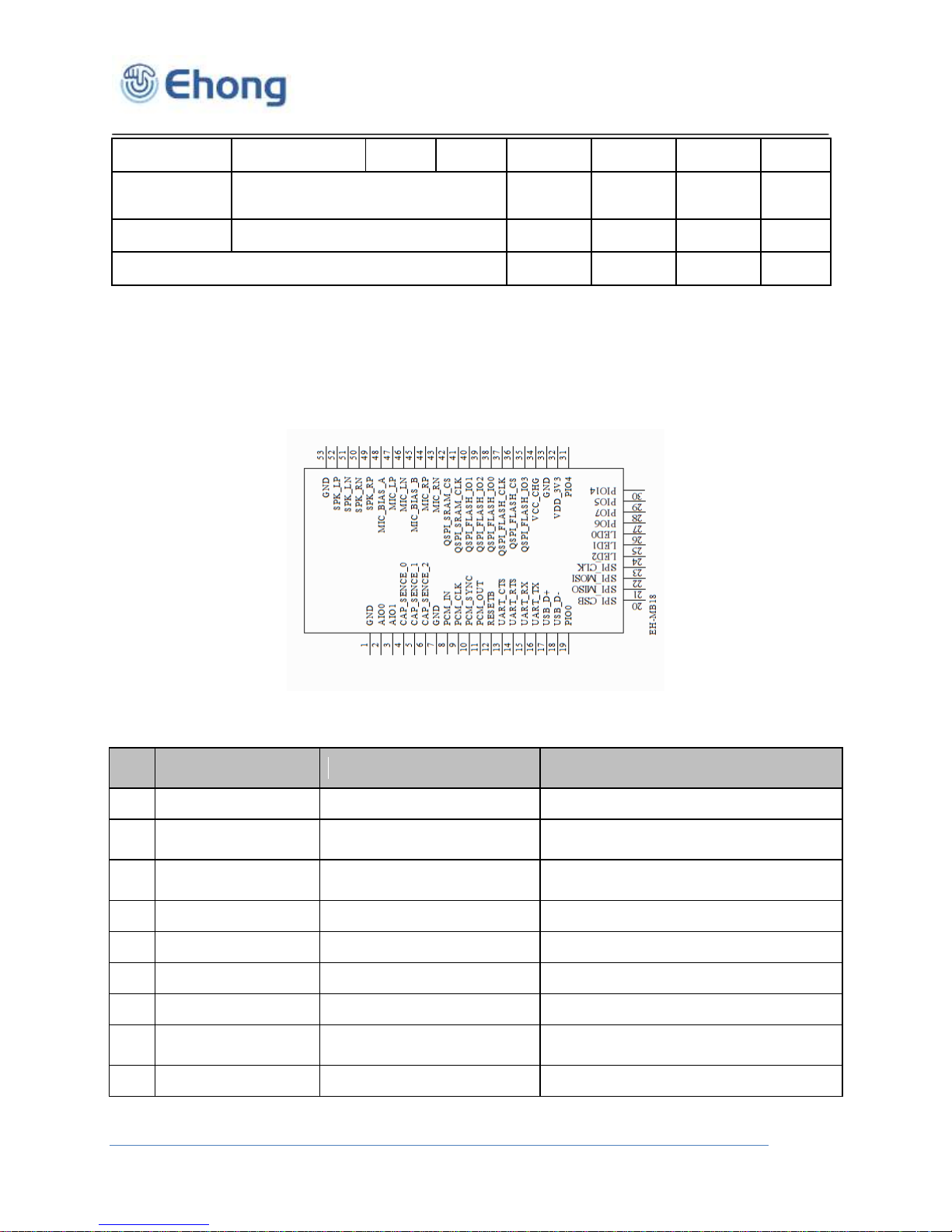
Pin
Symbol
I/O Type
Description
1
GND
Ground
Ground
2
AIO0
Bi-directional
Analogue programmable input/output
line
3
AIO1
Bi-directional
Analogue programmable input/output
line
4
CAP_SENSE0
Analogue input
Capacitive touch sensor input
5
CAP_SENSE1
Analogue input
Capacitive touch sensor input
6
CAP_SENSE2
Analogue input
Capacitive touch sensor input
7
GND
Ground
Ground
8
PCM_IN
CMOS Input, with weak
internal pull-down
Synchronous Data Input
9
PCM_CLK
Bi-directional with weak
Synchronous Data Clock
Table 7: Digital to Analogue Converter
5. Pinout and Terminal Description
5.1. Pin assignment
Ehong Technology Co., Ltd
Figure 1:Pinout of EH-MB18
 Loading...