

EHC NDIR120L, NINDSL120L, NDIR150L, NDIR180L, NDIR210L Installation & Maintenance Instructions Manual
...
Installation & Maintenance
Instructions
MARCH 2017
The Electric Heating Company Ltd
Unit 40 Block 5 Third Road
Blantyre Industrial Estate
Blantyre Glasgow
G72 0UP
Tel: 01698 820533
Fax: 01698 825697
email: info@electric-heatingcompany.co.uk
www.electric-heatingcompany.co.uk

01
EHC NEPTUNE
UNVENTED HOT WATER CYLINDERS
PAGE CONTENT
1 Introduction
2 Storage, Handling & Supply Requirements
3 Component Table
4 Siting the unit
5 General Installation
7 Discharge Arrangement
9 Technical Specifications: Slimline -
Direct & Indirect
10 Technical Specifications: Direct & Indirect
11 Technical Specifications: Solar Indirect
12 Solar Coil Installation
13 S-Plan Wiring Schematics
14 Commissioning & Servicing
15 Fault Finding & User Instructions
16 - 17 Specification & Performance
18 Commissioning Record
19-24 Service Record
25-26 Guarantee - Terms & Conditions
27 Gaurantee Card
INTRODUCTION
The EHC Neptune Unvented cylinder is made from
Duplex Stainless Steel for excellent corrosion resistance.
The EHC Neptune has a strong rust-resistant steel case
and is highly insulated with environmentally friendly
foam.
The EHC Neptune is supplied complete with all the
necessary safety and control devices needed to connect
to the cold water mains. All are pre-adjusted. High
quality controls have been selected to combine high flow
rate performance with minimum pressure drop to make
the EHC Neptune perform well in all areas, even those
with poor water pressure.
IMPORTANT NOTE TO
THE INSTALLER
Read these instructions before commencing installation. Unvented cylinders are a controlled service as defined in the
latest edition of the building regulations and should only be fitted by a competent person.
The relevant regulations are: England and Wales – Building Regulation G3, Scotland – Technical Standard P3, N Ireland –
Building Regulation Part F
After installation the commissioning record must be completed and left, with these instructions, with the householder for
future reference.
IMPORTANT NOTE TO THE INSTALLER
Read these instructions before commencing installation. Unvented cylinders are a controlled
service as defined in the latest edition of the building regulations and should only be fitted
by a competent person.
The relevant regulations are: England and Wales – Building Regulation G3, Scotland – Technical
Standard P3, N Ireland – Building Regulation Part F
After installation the commissioning record list must be completed and left, with these
instructions, with the householder for future reference.
02
EHC NEPTUNE
UNVENTED HOT WATER CYLINDERS
STORAGE PRIOR TO INSTALLATION
The EHC Neptune should be stored in its original packaging
in an upright position in an area free from excessive damp.
Regulations G3+L.
HANDLING PRODUCT
The EHC Neptune should be carried upright where possible.
Assessments of risks for carrying the cylinder should be
conducted. Use more than 1 person for carrying where
appropriate. Always follow latest guidelines for lifting
techniques, to avoid injury and damage to the product.
WATER SUPPLY
The EHC Neptune operates at 3 bar (controlled by the inlet
control set) and is capable of delivering over 50 litres per
minute. The high quality inlet control set has been designed
to make the most of the flow rates available, however the
performance of any unvented system is only as good as the
mains water supply. The maximum possible water demand
should be assessed, taking into consideration that both
hot and cold services are supplied simultaneously from the
mains.
The water supply should be checked to ensure it can
meet these requirements. If necessary, consult the local
water company regarding the likely pressure and flow rate
availability.
If measuring the water pressure, note that a high static
(no flow) mains pressure is no guarantee of good flow
availability. In a domestic installation 1.5 bar and 25 l/min.
should be regarded as the minimum. The maximum mains
pressure that the inlet control set can accept is 12 bar.
Consideration should be given to upgrading existing
½” (15mm) cold mains pipework to a larger size if the
recommended minimum pressure/flow rate is not being
achieved.
ELECTRIC SUPPLY
The EHC Neptune requires 240 Volt electrical supply for
the immersion elements. The electrical supply to each
immersion heater must be fused at 13A via a double pole
isolating switch to BS 3456. The cable must be at least
2.5mm2 heat resistant (85°C HOFR) sheathed flex complying
to BS 6141:1981 Table 8.
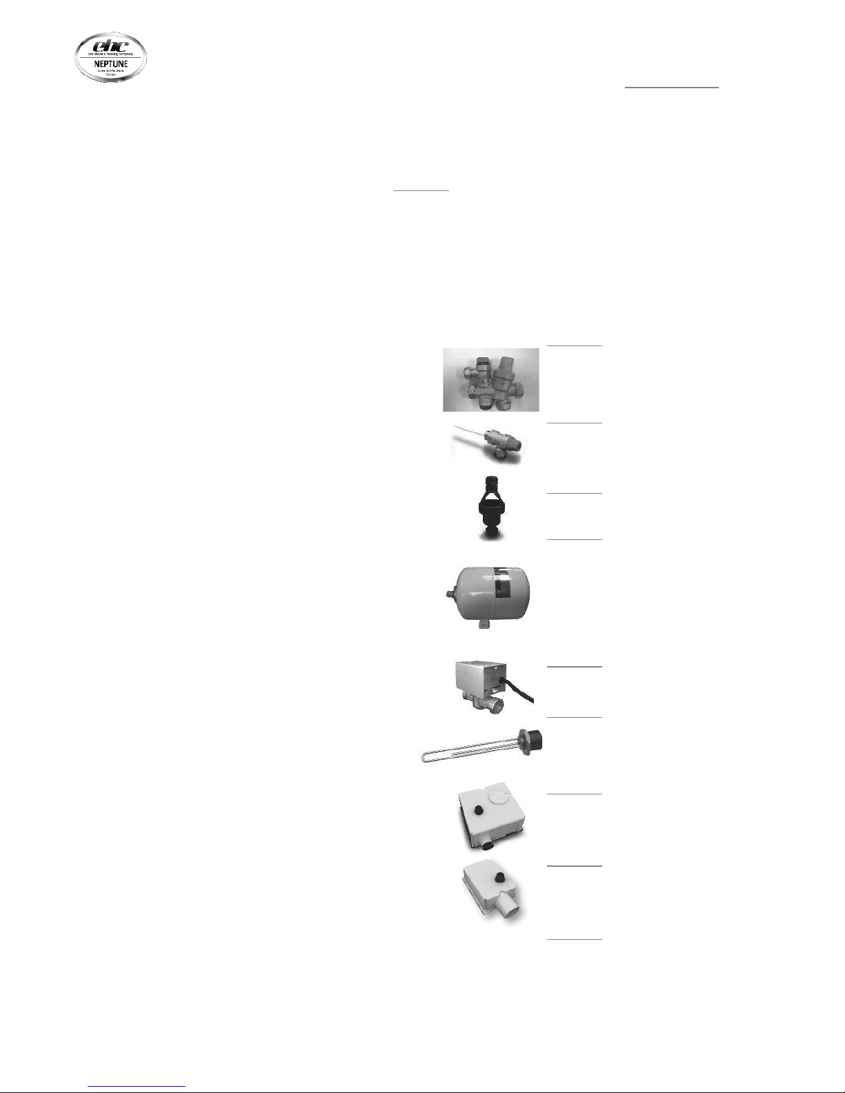
UNPACKING THE UNIT
The EHC Neptune comes complete with the fittings required
to complete the installation. Please see over for component
content list.
High flow rate inlet control set - 3 bar
PRV 6 bar Expansion Relief
Spare Part No. CB091
Temperature and pressure relief valve
Spare Part No. CB098
Acetal tundish 15 x 22 mm
Spare Part No. CB096
Incoloy long life
3 kW immersion heater
Spare Part No. CB099
Two port valve
Spare Part No. EC10008
Dual thermostat
Spare Part No. CB142
High limit thermostat
Spare Part No. CB135
Expansion Vessel
• 60- 250 ltr units - 18 ltr vessel
Spare Part No. CB144
• 300 ltr units - 25 ltr vessel
Spare Part No. CB145
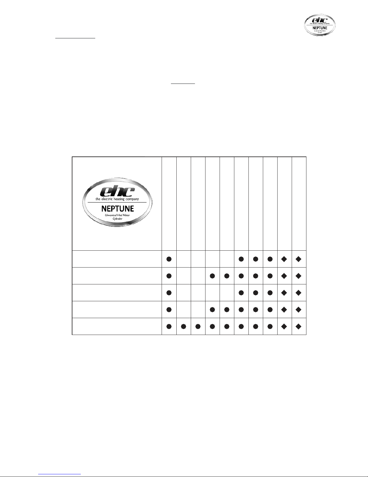
COMPONENT CONTENT TABLE
Inlet Control Set
• • • • •
Temp & Pressure Relief Valve
• • • • •
Tundish
• • • • •
Expansion Vessel
• • • • •
Immersion Heater
• • • • •
Two Port Valve
• • •
Dual Thermostat
• • •
Single High Limit Stat
•
Sensor Pocket Retaining Bungs
•
Installation & Maintenance
Instructions
• • • • •
Slimline Direct Models (Electric)
Slimline Indirect Models
Direct Models (Electric)
Indirect Models
Solar Indirect Models
Direct Models (Electric)
Indire ct Mod els (Single Coil )
Solar I ndirec t Models (Two Coils)
03
EHC NEPTUNE
UNVENTED HOT WATER CYLINDERS
SITING THE UNIT
The EHC Neptune can supply outlets above it or at some
distance from it. Site the unit to minimise “dead leg”
distances, especially to the point of most frequent use.
Outlets above the EHC Neptune will reduce the outlet
pressure available by 0.1 bar for every 1m of height
difference. The unit should be protected from frost.
Particular care is needed if sitting in a garage or outbuilding.
All exposed pipework should be insulated. EHC Neptune
must be installed VERTICALLY on a flat base capable
of supporting the weight of the cylinder when full. See
technical specification section (page 16) for weights. The
minimum recommended cupboard size is 650mm square.
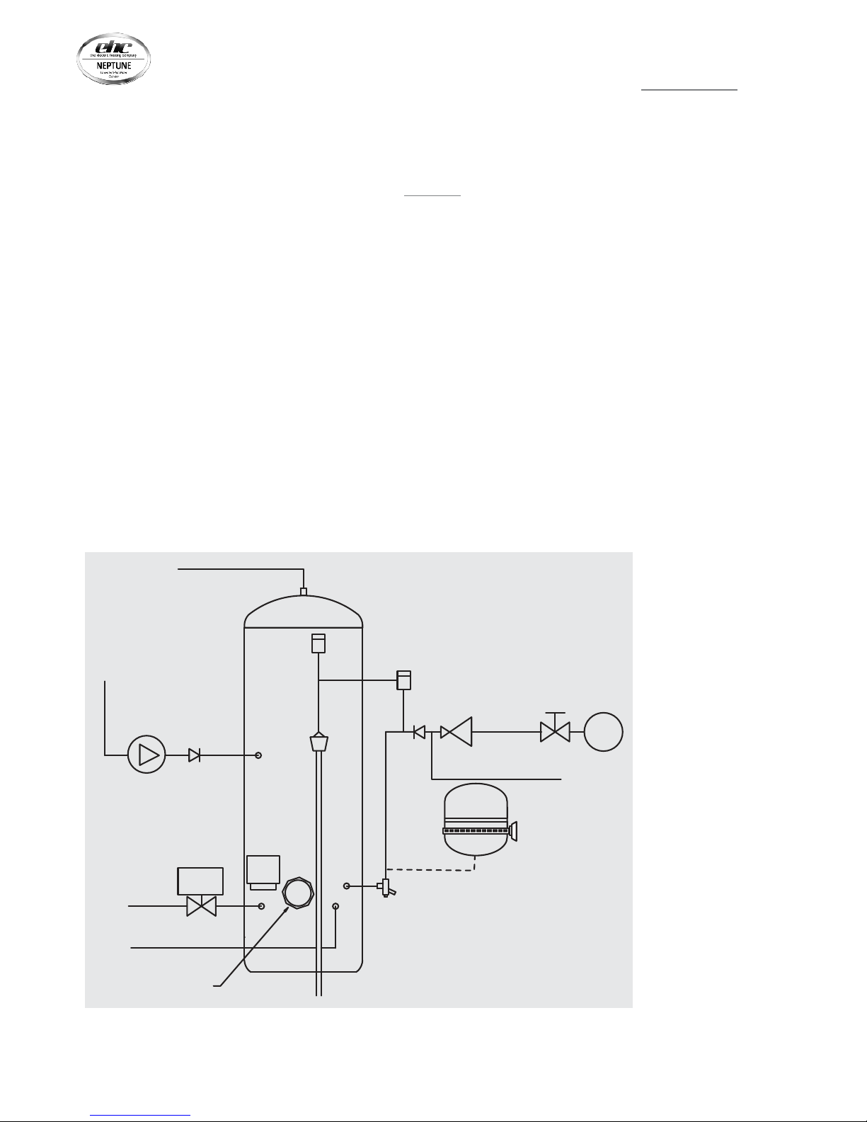
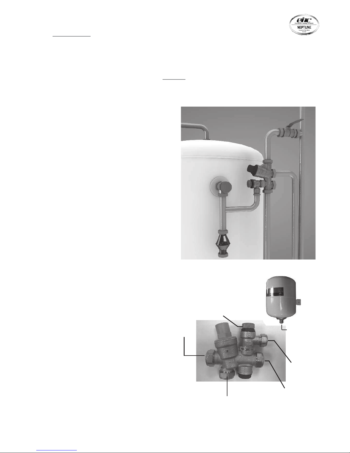
NOTES:
The pressure reducing
valve, non-return valve
and expansion relief valve
are combined together in
the inlet control set.
On 60 – 180 litre sizes
there is no dedicated
secondary return boss
and the secondary return
circuit should be tee’d into
the cold feed pipe just
above the drain elbow.
SCHEMATIC DIAGRAM
Access for maintenance of the valves should be considered.
Consideration should be given to position of discharge
pipes (tundish), drain valves - shall be positioned away from
electrical components.
The immersion heaters are 375mm long and care should be
taken to ensure that they can be withdrawn for servicing
if required. The discharge pipework from the safety valves
should fall continuously and terminate safely.
IMMERSION
HEATER
COLD
MAIN
ISOLATING
VALV E
PRESSURE
REDUCING
VALV E
NON
RETURN
VALV E
EXPANSION
RELIEF
VALV E
TUNDISH
TEMPERATURE
& PRESSURE
RELIEF VALVE
BALANCED
COLD
CONNECTION
COLD
INLET VIA
DRAIN
NON
RETURN
VALV E
BRONZE
PUMP
SECONDARY RETURN CIRCUIT
( 210, 250 & 300 L SIZES )
DUAL
STAT
2 PORT
VALV E
BOILER
FLOW
BOILER
RETURN
HOT OUTLET
EXPANSION
VESSEL
WITH WALL
BRACKET
04
EHC NEPTUNE
UNVENTED HOT WATER CYLINDERS
GENERAL INSTALLATION
COLD MAINS PIPEWORK
Run the cold main through the building to the place where
the EHC Neptune is to be installed. Take care not to run the
cold pipe near hot water or heating pipework so that the
heat pick-up is minimized. Identify the cold water supply pipe
and fit an isolating valve (not supplied).
A 22mm BS1010 stopcock can typically be used but a 22mm
quarter turn full bore valve would be better as it does not
restrict the flow as much. Do not use “screwdriver slot” or
similar valves. Make the connection to the cold feed of the
cylinder and incorporate a drain valve. Position the drain
valve no higher than the cold inlet to ensure sufficient
draining of cylinder when required. Position the inlet control
just ABOVE the Temperature & Pressure Relief Valve (TPRV)
mounted on the side of the cylinder. This ensures that
the cylinder does not have to be drained down in order to
service the inlet control set. Ensure that the arrow points
in the direction of the water flow. Select a suitable position
for the expansion vessel. Mount it to the wall using the
bracket attached to the vessel. Use suitable fittings capable
of supporting full vessel weight (and with appropriate
consideration to wall material). Connect the expansion
vessel to the cold feed pipework between the inlet control
set and the cold inlet on the cylinder. Ensure that the top of
the vessel is accessible for servicing.
CONNECTING TO THE CYLINDER
All of the pipework connections on the cylinder are 22mm
compression and supplied complete with gland nuts and
olives, in the Accessory Kit box. Only connect 22mm Table X
copper tube to these connections.
Cut the tube with a pipe cutter and ensure no sharp edges or
burrs protrude. Slide both gland nut and olive onto the tube
and push tube fully home into the connection, ensuring the
tube end fully bottoms on the connection recess. Smear the
outer wall of the olive with plumbing paste and tighten gland
nut in the prescribed manner. Upon filling/commissioning,
ensure all connections are completely watertight. Note:
No control or isolation valve should be fitted between the
expansion relief valve and the storage cylinder. The relief
valve connections should not be used for any other purpose.
(expansion vessel not to scale)
Turn to
test
Cold
Mains In
Balanced Cold
Connection
Outlet to Cylinder
Expansion
Relief to
Tundish
Expansion
Relief
Connection
05
EHC NEPTUNE
UNVENTED HOT WATER CYLINDERS

BALANCED COLD CONNECTION
If there are to be showers, bidets or monobloc taps in the
installation then a balanced cold supply is necessary. There
is a 22mm balanced connection on the inlet set.
HOT WATER PIPEWORK
Run the first part of the hot water distribution pipework
in 22mm. This can be reduced to 15mm and 10mm as
appropriate for the type of tap etc. Your aim should be
to reduce the volume of the hot draw-off pipework to a
practical minimum so that the time taken for the hot water
is as quick as possible. Where monobloc mixing taps and
showers are used, these should be installed to comply with
the Water Supply (Water Fittings) Regulations 1999. If these
devices are supplied with un-balanced supplies there should
be single check valves installed at both inlets, to stop over
pressurising of either supply.
PRIMARY COIL CONNECTIONS FOR INDIRECT UNITS
For Solar input models refer to pages 11-12 before making
any connections.
Connect the primary connections (Indirect only) using the
compression connections provided. The primary circuit must
be positively pumped. Gravity circulation is not suitable.
Either primary connection may be used as the primary flow,
reheat times are not effected. The primary circuit can be
open vented or sealed, with up to a maximum pressure of 3.5
bar. If you seal the primary circuit an additional expansion
vessel and safety valve is required. The boiler may be Gas,
Electric or Oil but must be under effective thermostatic
control. Uncontrolled heat sources such as some AGA’s, back
boilers, solid fuel stoves, etc. are NOT SUITABLE. Please
contact our Technical department for guidance. Connect the
two port zone valve ( indirect only ) into the primary flow
pipework. The direction of flow arrow should be towards the
primary flow connection.
SECONDARY CIRCULATION
The EHC Neptune can be used with secondary circulation.
An appropriate WRAS approved bronze circulator should
be used in conjunction with a non-return valve to prevent
backflow. On large secondary circulation systems it may
be necessary to incorporate an extra expansion vessel into
the circuit to accommodate the increased system water
volume. Secondary circulation should be avoided on Direct
electrically heated units being used on off-peak electricity
tariffs.
A secondary return boss is fitted as standard on 210, 250
& 300 ltr units. On smaller sizes, tee into the cold feed pipe
above the drain.
IMMERSION HEATERS
Only immersion heaters with a thermal cut-out may be used.
To help ensure this, the immersion heaters have a special
1 3/4” thread. They are rated at 3kW at 240V and are of a low
noise Incoloy construction.
They have both a thermostat and a high limit cutout. Please
order the correct replacement via ourselves; fitting nonapproved immersions may affect your guarantee. When
fitting, ensure the ‘O’ ring is positioned correctly on the head
of the immersion heater and lubricate before fitting. Fit it
by hand until almost home then tighten gently as the ‘O’
rings will seal easily. The electrical supply to each immersion
heater must be fused at 13A via a double pole isolating
switch to BS 3456. The cable must be 2.5mm2 heat resistant
(85°C HOFR) sheathed flex complying to BS 6141:1981 Table
8. Do not operate the immersion heater/s until the unit
is full of water. Do not operate the immersion heater/s if
any sterilisation liquid is in the cylinder as this will cause
premature failure.
ELECTRICAL CONNECTIONS
Complete the wiring – use the appropriate wiring diagrams
on page 12- 13.
06
EHC NEPTUNE
UNVENTED HOT WATER CYLINDERS
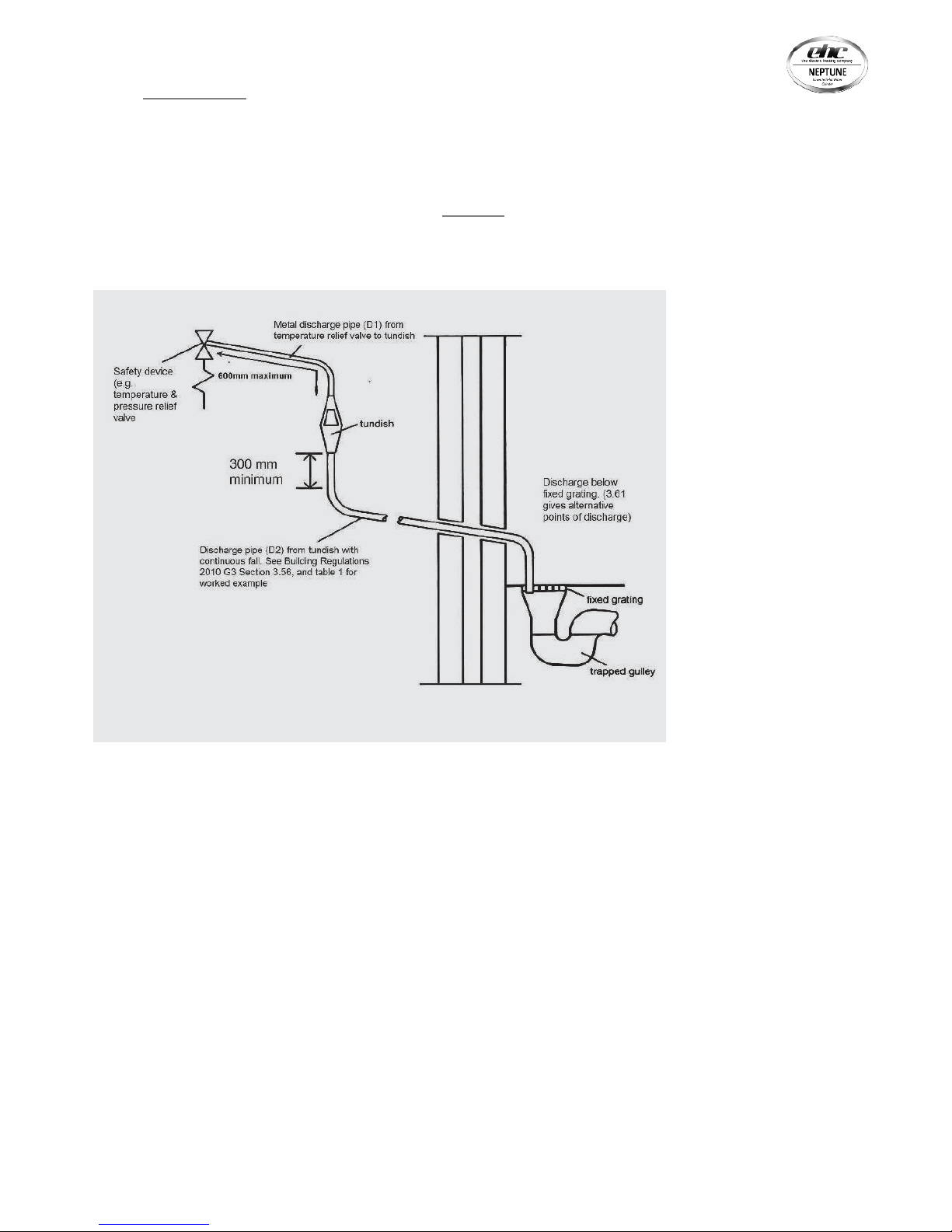
DISCHARGE ARRANGEMENT
Position the inlet control group so that the discharge from
both safety valves can be joined together via a 15mm end
feed Tee (see diagram above). Connect the Tundish and
route the discharge pipe. The discharge pipework must
be routed in accordance with Part G3 of schedule 1 of the
Building Regulations. The information that follows is not
exhaustive and if you are in doubt you should seek advice.
The two safety valves will only discharge water under fault
conditions. When operating normally water will not be
discharged. The tundish should be vertical, located in the
same space as the unvented hot water storage system and
be fitted as close as possible to, and lower than, the safety
device, with no more than 600mm of pipe between the valve
outlet and the tundish. The tundish should be positioned
away from electrical devices.
Any Discharge should be visible at the tundish. The tundish
should be located such that any discharge is visible. In
addition, where discharges from safety devices may not
be apparent, e.g. people with impaired vision or mobility,
consideration should be given to the installation of a suitable
safety device to warn when discharge takes place, e.g.
electronically operated.
Diagram of a typical discharge pipe arrangement (extract from
Building Regulation G3)
Note: The discharge will
consist of scalding water and
steam. Asphalt, roofing felt
and non-metallic rainwater
goods may be damaged by
such discharges.
Note: D2 pipe from tundish
is now allowed to be
installed in soil stacks within
premises. This activity is not
recommended as discharge
from T&P may continue for
long periods of time. It is
the installer’s responsibility
to ensure the discharge
pipework can support the
discharge for prolonged
periods.
If used follow guidance on
mechanical seal without
water trap given in G3
Building Regulations.
As discharge can be in
excess of 90oC discharge
into plastic pipework is also
not recommended.
07
EHC NEPTUNE
UNVENTED HOT WATER CYLINDERS

The discharge pipe (D2) from the tundish should:
A) Have a vertical section of pipe at least 300mm long,
below the tundish before any elbows or bends in the
pipework.
B) Be installed with a continuous fall of at least 1 in 200
thereafter.
The discharge pipe (D2) from the tundish should be of metal
or other material that have been demonstrated to be capable
of withstanding temperatures of the water discharged.
The discharge pipe (D2) should be at least one pipe size
larger than the nominal outlet size of the safety device
unless its total equivalent hydraulic resistance exceeds that
of a straight pipe 9m long i.e. discharge pipes between 9m
and 18m equivalent resistance length should be at least two
sizes larger than the nominal outlet size of the safety device,
between 18 and 27m at least 3 sizes larger, and so on. Bends
must be taken into account in calculating the flow resistance.
Refer to diagram 1, Table 1 and the worked example. An
alternative approach for sizing discharge pipes would be to
follow BS670 ce of services supplying water for domestic
use within buildings and their curtilages.
The discharge pipe (D2) should terminate in a safe place
where there is no risk to persons in the vicinity of the
discharge. Examples of acceptable discharge arrangements
are:
a. To a trapped gully with the end of the pipe below
the fixed grating and above the water
seal.
b. Downward discharges at a low level; i.e. up to 100mm
above external surfaces such as car parks, hard standings,
grassed areas etc. are acceptable providing that where
children play or otherwise come into contact with
discharges, a wire cage or similar guard is positioned to
prevent contact whilst maintaining visibility.
c. Discharges at a high level; e.g. in to metal hopper
and metal down pipe with the end of the discharge pipe
clearly visible or onto a roof capable of withstanding high
temperature discharges of water and 3m from any plastic
guttering systems that would collect such discharges.
d. Device to warn when discharge takes place.
WORKED EXAMPLE
The example below is for G1/2 temperature relief valve with
a discharge pipe (D2) having 4 No. elbows and length of 7m
from the tundish to the point of discharge.
From Table 1:
Maximum resistance allowed for a straight length of 22mm
copper discharge pipe (D2) from a G1/2 temperature relief
valve is: 9.0m. Subtract the resistance for 4 No. 22mm
elbows at 0.8m each = 3.2m. Therefore the maximum
permitted length equates to: 5.8m. 5.8m is less than the
actual length of 7m therefore calculate the next largest size.
Maximum resistance allowed for a straight length of 28mm
pipe (D2) from a G1/2 temperature relief valve equates to:
14m. As the actual length is 7m, a 28mm (D2) copper pipe
will be satisfactory.
TAB L E 1
Sizing of copper discharge pipe ‘D2’ for a temperature
relief valve with a G1/2 outlet size (as supplied).
Size of
discharge
pipework
Maximum length of
straight pipe
(no bends or
elbows)
Deduct the figure below
from the maximum length
for each bend or elbow in the
discharge pipe
22mm Up to 9m 0.8m
28mm Up to 18m 1m
35mm Up to 27m 1.4m
08
EHC NEPTUNE
UNVENTED HOT WATER CYLINDERS
 Loading...