

EHC EH800.38.63, EH1500.98.63, EH2000.128.63, EH2400.128.63, EH500.68.34 Installation & Operating Instruction
...
The Combination Range of
Electric Radiators
The Electric Heating Company Limited
Unit 40 ,Block 5, Third Road,
Blantyre Industrial Estate,
Glasgow
G72 OUP
Tel: 01698 820533
info@electric-heatingcompany.co.uk
www.electric-heatingcompany.co.uk
the electric heating company
INSTALLATION
&
OPERATING INSTRUCTIONS
THESE INSTRUCTIONS SHOULD BE READ CAREFULLY AND RETAINED
FOR FUTURE REFERENCE.
BE SURE TO OBSERVE ALL LABELS AND WARNINGS ON THE
APPLIANCE.
Fax: 01698 820533
CONTENTS
1.
Safety information ...................................4
2.
General information ..................................2
3. Installation .........................................5
4. Operating instructions ...............................10
5. Operating safety .................................. 10
6. Technical data .....................................13
7.
Control Types......................................14
This appliance is not intended for use by persons (including children) with reduced physical, sensory
or mental capabilities, or lack of experience and knowledge, unless they have been given supervision
or instruction concerning use of the appliance by a person responsible for their safety. Young children
should be supervised to ensure that they do not play with the appliance;
Electrical Connections
IMPORTANT
The wires in the mains leads are coloured in accordance with the following code:
GREEN & YELLOW: EARTH
BLUE: NEUTRAL
BROWN: LIVE
WARNING – THIS APPLIANCE MUST BE EARTHED
The installation of this appliance should be carried out by a competent electrician in
accordance with I.E.E. Regulations for Electrical Equipment.
The radiator is fitted with a standard UK 3 pin plug that can be directly connected to an
electrical socket. Care must be taken when connecting radiators in this way not to overload the
ring main circuit. If you are unsure contact a qualified electrician.
Alternatively, the mains cable can be cut to length by a Qualified Electrician and connected to
a suitable 13A DP Switched Fuse Connection unit adjacent to the radiator. This connection unit
should comply with BS 1364-4 having a contact separation of at least 3mm. Please ensure that
the electricity supply is disconnected prior to using this installation method.
Page
Page 1

1. General Information
EHC Combination Electric radiators have been designed using the latest technology to create an
elegant solution for all hard to heat situations. They can be installed in almost any location apart from
the safety restrictions noted in this manual.
The range has been developed to provide a flexible solution for electric heating in Domestic properties,
Conservatories, Holiday homes, Offices and any temporary heating situation.
Our unique patented ’Magmatic’ heating tablets provide the heat source for your new radiator. Whilst
the radiator is classed as a 100% efficient Direct Acting appliance, the heating tablets provide partial
storage to prolong your heating comfort and to reduce running costs. The radiator has a robust body
which incorporates a spot welded high fin surface area to ensure that there are no contraction noises
during the heating cycle. The high fin design boasts 6 times the normal radiator surface area to provide
a balance of Convection and Radiant heat for your added comfort.
The radiators can be simply plugged in to a Standard socket or Hard wired to an existing
spur connection. The range has the flexibility of being Wall mounted or free standing on Castors or
Feet.
For added versatility we can supply Conservatory radiators which are also ideal for use below windows
with low sills.
Control types:
All our standard model sizes are supplied with a TEI 1 manual room thermostat. For a fully controllable
central heating system, the radiators can be installed with our EHC Control Box, Single or twin Zone
Programmer's and Room Thermostats to comply with the latest Building Regulations.
In addition to the above we also supply Radio Frequency controlled radiators which provide all the
benefits of the standard version however the control wiring is eliminated. These models can be
controlled by our T-Pod and T-Basic Programmers.
Also available is our TDI range of Electric Radiators. Simply plug in the radiator to a standard 13amp
socket and control by TIME & TEMPERATURE using the TDI control located within the side of the
radiator.
WiFi Control:
DSR WiFi Control is our easy to use App based control system. To take benefit of this feature you
simply need to purchase and connect the radiators to our DSR Wifi Gateway.
The DSR WiFi App gives you total control of all your heaters independently or in groups should you
choose. The system can be controlled from a computer,smart phone or tablet using our Free App.
Additionally, adding an optional Power Meter to the system will give you further controllability over the
total available power within your home. The Power Meter constantly monitors the whole house electrical
demand. If the set demand is ever reached the system will temporarily disable your chosen heaters until
the demand is reduced where they will be reactivated automatically.
All EHC radiators are manufactured to the highest safety and quality Standards. Each radiator is CE
Marked and carries all the necessary European Approvals. Each radiator is fully checked and
tested prior to leaving the factory and as such is packed with full Quality certification.
We hope you enjoy the comfort provided by this superior product and we look forward to being of
assistance to you in the future.
Page 2
2. Safety Information
Handling
This radiator is very heavy. Take adequate precautions when lifting and manoeuvring it. Always
assess the load, and seek assistance with heavy or awkward loads that are beyond your
capabilities.
Positioning
This radiator is very heavy. In order to maintain stability and to ensure its future safety in use,
it is essential that the radiator is FIXED SOUNDLY TO A WALL and that the brackets are
mounted on a FIRM, LEVEL SURFACE. Castors or Feet can be purchased as an accessory.
Care should be taken to avoid irregular surfaces.
It is important that the following instructions are strictly followed.
Keep the following minimum safety distances to avoid fire risk due to high surface
temperatures of the appliance during heating cycles:
Lateral heating walls – masonry
........................................................ 50 mm
Lateral heating walls – combustible matter ...................................... 100 mm
Heating walls above floor ................................................................... 80 mm
Cover plate – combustible covering installed on top of it ................ 150 mm
Cover plate – non-combustible covering installed on top of it ......... 100 mm
Please note that our IPX4 rated models should be used in bathrooms.
Portable radiators must not be fitted in bathrooms or wet areas.
CAUTION – This radiator must not be located below or in front of a fixed socket outlet.
DO NOT POSITION under windows where curtains may contact the radiator.
DO NOT PLACE THE APPLIANCE in the vicinity of a swimming pool.
Installation
It is important that the fixing device chosen is appropriate to the wall material to which the
radiator is being fixed. Some modern internal
building materials are very low density block
and require specialised fixing devices to provide a safe, secure installation.
Ongoing safety
CAUTION – If during any reassembly of the radiator, a part of the thermal insulation shows
damage or deterioration which may impair safety, it should be replaced with an identical part.
CAUTION – In order to avoid overheating, do not cover the radiator.
DO NOT COVER OR OBSTRUCT the surfaces of the appliance.
DO NOT PLACE OBJECTS in contact with the radiator.
Page 3
3. Installation
Preparation
1. Before beginning, remove the radiator and parts from
the box and check everything is present and correct.
In addition to the radiator body, there should
be a top
grille, a pair of mounting brackets, four suspension
hooks, a set of mounting screws & plugs and an
instruction manual.
20 cm 37 cm 50 cm 67 cm
80 cm 110cm 140 cm
Rad. Length(cm)
38
55
68
85
98
128
158
Bracketseparation(cm)
20
37
50
67
80
110
140
Page 4
Note: Setting the brackets to the Minimum recommended 18cm to the lower fixing point will leave a
distance of approx 8.7cm from the floor to the bottom of the heater
38
55
68
85
98
128
158
3. Installation (cont.)
Wall fixture and fittings
2. Drill, plug, and secure the brackets to the wall. Appropriate fixtures must be used depending
on the wall material:
Solid brick/High density block walls
These must be drilled and plugged with the Rawlplug No. 10 size fibre inserts provided. The
correct size of drill (5.5mm) should be used and the hole should be drilled to a depth of
8mm greater than the length of the Rawlplug so that the fixing is made below the plaster
layer.
Low density block walls
A special fixing, such as Unifix LB70 should be employed, (following fixing instructions).
Panelled internal walls
It is preferable to locate the studding and use the No.10 size wood screws provided. Where
it is not possible to locate the studding use Hollow wall anchors and securely fasten the
brackets to the plasterboard when this method is used we recommend that radiator feet are
used to take the full weight of the radiator. For other wall materials the wall panel
manufacturer should be consulted for details of suitable wall fixing devices.
Note: Radiators will be set to an approximate height of 185mm from the floor when support
feet are used.
3. Fit two Small suspension hooks into the bottom slots in the brackets, and hang the bottom
of the radiator on them. Make sure the radiator is sitting right back on the hooks and not just
resting on the fins.
4. Fit the other two Large suspension hooks in
the top slots of the brackets, and lift them up.
Push the radiator back against the wall and
drop the suspension hooks back down to lock it
in position.
5. The top grille
of the radiator can then be fitted
and secured with the securing screws at each
end.
Page 5
3. Installation (cont.)
6. At the bottom of the radiator, next to the mains
connection there is a small temperature sensor.
Loosen the gland and pull the sensor down by
approx 5 cm, then re-tighten the gland. This
enables the radiator to gauge the room’s
temperature.
Electrical installation
• The appliance has been designed to be connected to 230 V (nominal) alternating current (AC);
50Hz supply and comes with a standard UK 13A 3 pin plug that can be directly connected to an
electrical socket.
• All electrical installation work, in particular protective measures, must be carried out in
compliance with the BS7671 regulations, statutory provisions and ‘best industry practice’ of the
respective utilities provider.
• The electrical installation may only be carried out in compliance with the installation instructions
and by a competent suitably qualified electrical engineer.
WARNING - THIS APPLIANCE MUST BE EARTHED
• For each supply, a means for disconnection must be incorporated in the fixed wiring by a
double pole switch with a contact separation of a minimum of 3mm and in accordance with the
current IEE Wiring Regulations.
• The heater must not be installed immediately below a fixed socket outlet or any combustible
object.
• If multiple heaters are to be installed and plugged into the domestic socket ring circuit then
considerations should be made in regards to the total circuit loading.
Note:
Only IPX4 radiators are suitable for installation in bathrooms which allows for the
heater to be installed within Zone 2 as per regulation 701.32.4. Regulation 701.411.3.3 of
BS7671 means that all circuits within a location containing a bath or shower will require RCD
protection not exceeding 30 mA and have the characteristics specified in regulation 415.1.
Local isolation should be provided for the heater however the isolation device must be installed
out with all zones and in compliance with regulation 701.512.3 and Section 53 of BS7671.
‘Bathroom Zones for Radiator installation’ Zone 2
Zones
Page 6

L
4
1
2
A1
A2
3A
Radiator
Radiator
Radiator
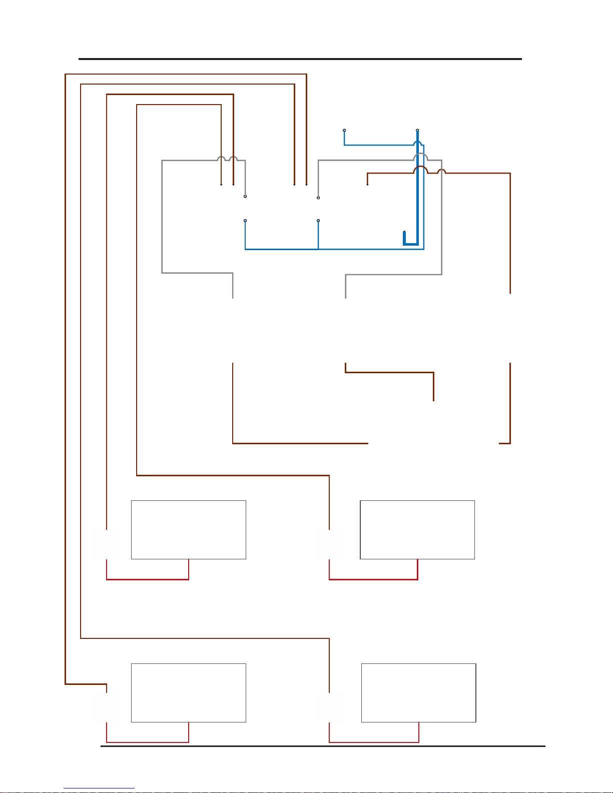
3. Installation (Single Zone Wiring)
Control wiring to be
1.5mm Twin & Earth
cable.
Radiator wiring should be a minimum
of 2.5mm Twin & Earth cable.
Page 7
7.
ZONE 1
RADIATOR
ZONE 1
RADIATOR
ZONE 2
RADIATOR
ZONE 2
RADIATOR
L
3
4
A1
A1
A2 A2
1 1
2 2
3. Installation (Twin Zone Wiring)
3A
Control wiring to be
1.5mm Twin & Earth
cable.
Radiator wiring should be a minimum
of 2.5mm Twin & Earth cable.
Page 8
8.

3. Installation (cont.)
Control cabling – RF models
All Radio Frequency radiators come complete with a pre-wired receiver in T-RF which is
controlled by either the T-Pod or T Basic Thermostat.
9. T-Pod installations
a
b
Follow the instructions outlined in section 7 for single radiator installations.
Locate the T-Pod programmer on a suitable wall in the same room as the radiator.
Configure the T-Pod programmer and receiver in T-RF located on the radiator.
According to the instructions included in the T-Pod packaging. Set the required
program times and temperatures.
10. T-Basic installations
a
b
c
d
Follow the instructions outlined in section 7 for single radiator installations.
Locate the T-Basic digital room thermostat on a suitable wall in the same room as
the radiator.
Configure the T-Basic digital room thermostat and receiver in T-RF located on the
radiator according to the instructions included in the T-Basic packaging.
Set the required temperature by adjusting the +/- buttons.
11. TDI Installations
a
b
Follow the instructions outlined in section 7 for single radiator installations
Configure the TDI Digital Control Display according to the instructions on
page 12 & 13 of this manual. Set the to set the radiator setting the required
time and temperature.
CAUTION - After completion of works all electrical connections should be tested for
tightness.Additionally an electrical safety check should be carried out ie: short circuit,
earth continuity, resistance to earth and polarity check and all the relevant test
certificates produced
Installing castors and feet
12 . All radiators are supplied with wall mounting brackets, however with the exception of the
Towel Rail & Tall heaters, optional feet or castors can be purchased.
Consult the information leaflet that comes with castors or feet for fixing instructions.
Page 9

4. Operating Instructions TE1(e4)
Instructions E4 manual Electronic Thermostat
Technical Details:
• Easytouse
• Temperaturerangefrom5°Ctill30°C
• Integratedtemperaturesensor
• Frostprotectionsetting
• 2xLEDdisplaylights
Operating display lights
OFF
5°C
10°C20°C
25°C
30°C
15°C
Radiator is “ON“
Power going to
the tablets.
Radiator is “ON”
No power going to
tablets.
Radiator is
“OFF”
Page 10

DTi Instructions Digital Thermostat
The Keyboard consists of four buttons:
(+ ) Adjustment increase
( ) Adjustment decrease
Mode selection button
Power ‘on/off’ button
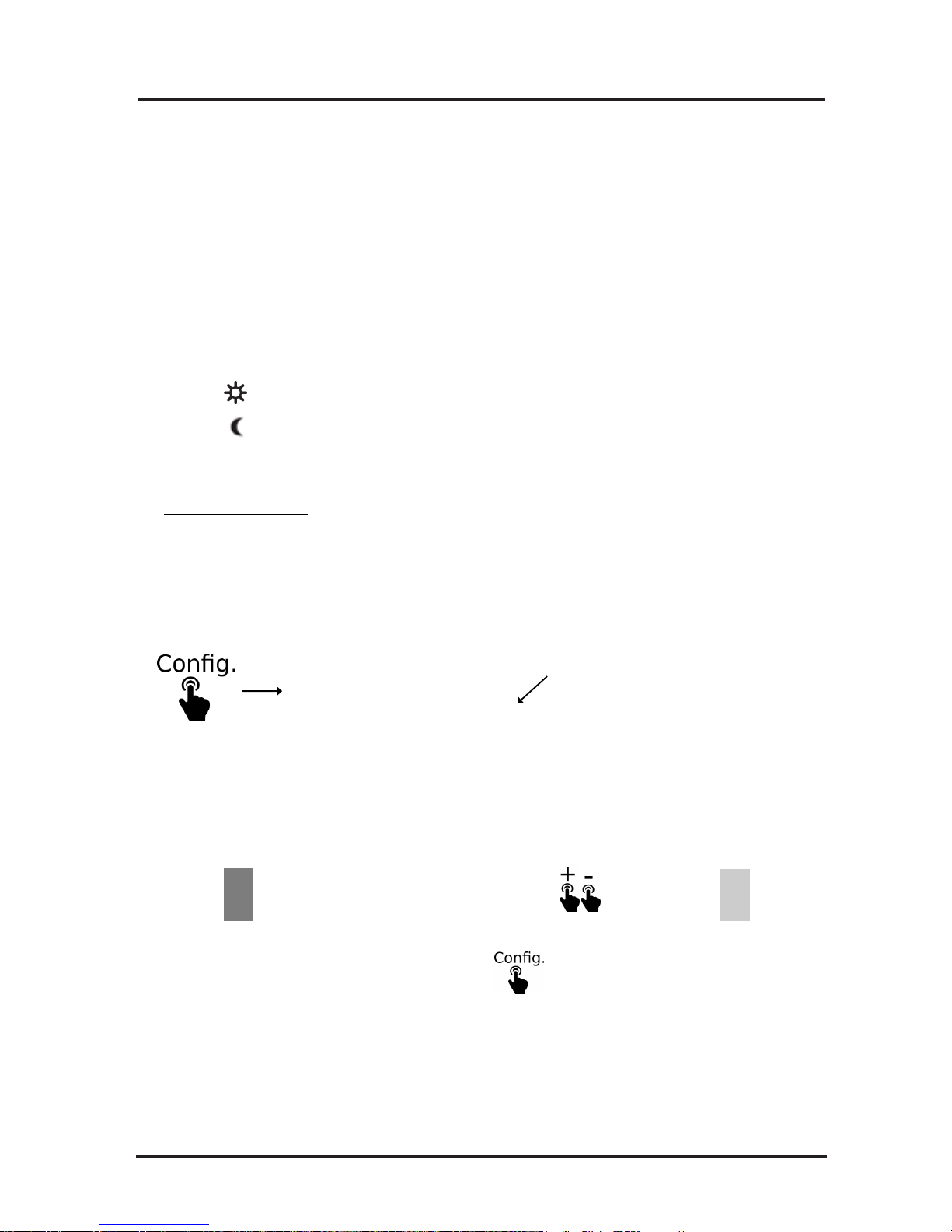
Mode button:
The Mode button has four stages of operation
‘Comfort’ ‘Economy’ ‘Frost Protection’ and
‘OFF’:
> Comfort Mode: The sun icon
is displayed and this is normally used for
day time setting.
> Economy Mode: The moon icon is
displayed and this is normally used for a night
time setting.
> Frost Protection Mode: The frost icon
is displayed and this is normally used
for periods of absence from the house during
winter months. This is a factory pre-set mode
and is set to 7ºC
> OFF: The digital display will show two small
horizontal bars in-line with each other denoting
that the radiator is still switched on but that no
other program mode is required.
Note.
There will be a 2 deg C difference between
Comfort and Economy settings as default.
Normal Operation:
Switch the radiator on by pressing the
icon and select either the Comfort or
Economy Mode of operation. This is achieved
by briefly pressing the Mode button until the
desired icon is showing on the digital display.
The digital display will also show the current
temperature of the room. To check or set the
desired room temperature briefly press the + or
– button and the digital display will show the
thermostat temperature setting. If you require
the room thermostat temperature setting to be
increased or decreased, briefly press the + or
– button until the desired room thermostat
temperature setting is showing. The digital
display will flash approximately 4 times at 1
second intervals and then the digital display
will stop flashing and display the current room
temperature. If the current room temperature
is lower than the room thermostat temperature
setting you set as above, then the digital
display will show ‘on’ in the upper right section
of the display. This indicates that the radiator
is calling for heat and after a few seconds you
will be able to feel the heat emitting from the
top of the radiator.
Note: The digital display will also show a
clock icon periodically; however this
function is not installed in this radiator and
therefore should be ignored.
Keypad Locking:
To lock the keypad, simultaneously press the
+ and – buttons for 5 seconds. After 5 seconds
the ‘LO’ message will be displayed indicating
the keypad is now locked. Once the keypad
has been locked pressing on any button will
display ‘LO’ on the digital display.
To unlock the keypad, simultaneously press
the + and - buttons for 5 seconds, LO message
will disappear and the digital display will revert
back to normal display.
4. Operation Instructions DTi
Page 11

4. Operation Instructions TDi
TDi Instructions for use.
Setting the Time and Day
Step 1:
Step 2:
Step 3:
Step 4:
Step 5:
Step 6:
Ensure the radiator is in OFF Mode. The symbol will be on the top
left of the display.
Push the Right Hand Side mode button once to access the Time and
Day Setting. The days down the right hand side will flash.
Press the + or – buttons to set the day (1 is Monday, 2 is Tuesday,
etc), then press the OK button to confirm.
Press the + or – buttons to set the hour
then press OK to confirm.
Press the + or – buttons to set the minutes then press OK to confirm.
Press the Left Hand Side On/Off button once to exit the setting mode.
Setting Temperatures and Program
Sun –
Moon –
Frost –
The sun setting is indicated by the sun symbol and is the setting the user typically uses during
theday.Thesunsettingisnormallysetbetween18and20°Celsius.
The moon setting is indicated by the moon symbol and is the setting the user typically uses
during the night or when the property is vacated for a short period of time. The moon setting is
normallysetbetween15°and17°Celsius.
The frost setting is indicated by the snowflake symbol and is the setting the user typically uses
tohavetheradiatorturnoff.Thefrostsettingisnormallysetat5°Celsius.
STEP 1 – Setting the Desired Room Temperature (Sun Setting)
Push the On/Off button so that the symbol disappears and you can see the sun
symbol at the top of the display.
Press + or –
button to set the desired temperature.
Press the small information button below the i symbol on the display to see the
actual current room temperature.
STEP 2 – Setting the Frost Protection Temperature (Frost setting)
Push the Right Hand Side mode button so that the sun symbol disappears and the
snowflake symbol appears.
Press the + or – button to set the frost protection temperature.
This will be the protection temperature that the room will not drop below, even
whentheradiatorisoff.Normally5°or7°Celsius.
STEP 3 – Setting the Set Back Temperature (Moon Symbol)
Push the mode button so that the frost symbol disappears and the moon symbol
appears Press the + or – button to set the set-back temperature.
Set-back temperature is a lower temperature that is usually applied when the property is vacated for a short
period of time (when people are at work), or during the night time (when people are in bed).
If the set-back temperature is being used then the heater will start to work when the room temperature drops
below the chosen setting.
Page 12

Step 1 –
Step 2 –
Push the small button below the PROG symbol.
There will be 00:00 hrs in the middle of the screen, a block flashing on
the left hand side and a triangle pointing to the number 1 (top right
hand side of the screen).
The heater is asking what the temperature / time selection should be
chosen from midnight on Monday.
Across the bottom of the screen there are Sun , Moon and Frost
symbols.
Choose the temperature setting you would like at midnight on a
Monday by pressing the small button under the corresponding symbol.
E.g. most people will use the moon setting while sleeping or when they are away from home.
The screen will now show 01:00 in the middle of the screen, it is now asking what temperature /
time setting you require from 01:00 hrs onwards on that day.
Step 3 – Continue to choose which temperature / time setting you require to be used for each hour of that day.
E.g. if you wanted the radiator to turn on at 06:00 hrs you would press the comfort setting Sun
when the display is showing 06:00 hrs and so forth.
Step 4 – If you want to copy your temperature / time settings from one day to another, this can simply be
done by pressing and holding the small OK button on the RHS. You will see the triangle
pointer moving to the
next day. (Your previous settings are now copied to the next day)
Auto Program Overrides
1. Timer Mode
A set temperature
can be selected for a certain period of time.
Step 1 –
Step 2 –
Step 3 –
In the auto mode press the button below the hour glass once.
Set the desired temperature with the buttons below the + and – symbols, then press the OK button
to confirm.
Set how long the heater is required to be on with the buttons below the + and – symbols, then
press the OK button to confirm.
The timer will now countdown the time you have set. To cancel the timer mode, press the OK button.
2. Holiday Mode
You can set the radiator to be off if you are going to be absent from the property.
Step 1 –
Step 2 –
Press the suitcase button to select this mode.
Set the number of days of absence by pressing the + or – buttons, then confirm by pressing OK.
While in holiday mode the heaters will keep the room temperature above the frost setting temperature.
To cancel this mode, press on the OK button again.
3. Locking the keypad
Press the – and + button for 5 sec., than a key symbol appears briefly on the display. If you want to unlock the
TDI, press the – and + button again.
STEP 4 – Auto Mode
Push the mode button so that the moon symbol disappears and the auto symbol appears.
In this mode the heater will now follow the temperatures that have been selected for specific times of the day.
The heater has a default profile already displayed.
Choosing a program:
4. Operation Instructions TDi
Page 13

4. Operation Instructions DSR Wifi
DSR Temperature Setting, Programming and Wifi Setup
Page 14
1.0 Manual Instructions
Modes
The radiator can work in 3 different modes by pressing the "Mode" button
Auto Mode
The set temperature varies automatically following the Programmed Schedule, based
on the 3 custom temperatures selected. Each LCD Block in
dicates what
temperature is active at that time.
Manual
Mode
The "Set Temperature" only changes if the user modifies it by pressing the + and -
buttons.
OFF.
The radiator will not heat, but can receive remote instructions if linked to a gateway
that is connected to the internet.
Auto Mode
Manual Mode Off
Note:
When in "Auto Mode" manually adjusting the temperature
will Activate the heater for 1.5 hours, after this time period
has lapsed the heater will automatically revert back to the
original program settings.
2.0 Setting Temperatures
4. Operation Instructions DSR Wifi
Page 15
Press
Temperature symbol should be flashing at
this stage,
(if not select by pressing the + or - key)
At Home
Sleeping
The DSR controller has 3 temperature ranges,
-Comfort (
) Normally when at home.
-Economy ( ) Normally used at night or for brief absence periods
-Frost Protection (
) Normally used when away from home
.
To Set Temperatures
to exit.
Now Press Select your temperature, change by pressing the buttons then press to confirm .
Once you have chosen your temperature ranges press
At Work / Away

3.0 Setting Program Time and Day
Symbol Indication
4. Operation Instructions DSR Wifi
Page 16
To start programming.
Day of the week
Temperature/hour bar
Hour
Temperature Range
1. Press and hold for 3 seconds.
Sleeping
At Work / Away
At Home
2. Press
To select your temperature range
followed by to set your times by hour.
Select
3. To change the temperature range during programming, Press
temperature then program again using the button.
the controller4. Once you have programmed a 24 hour period
will automatically move onto the the next day. Now program all 7 days
in this way.
Once all 7 days are programmed the controller will then ask you to select the Day of the week (1 being
Monday). Select by pressing the + and - buttons, Save by pressing the OK button. The next stage is to
set the real time. Use the + and - buttons to select the Hour's and Min's, save by pressing OK.
Tip: Quick Real Time Setting.
To change the real time clock without having to go through previous settings.
Press and hold for 3 seconds to show this screen release and press Config
once again to enter Quick Real time settings.

4.0 Keypad Locking
4. Operation Instructions DSR Wifi
Page 17
LOCK
Press and Hold the + and - buttons for 3 seconds to Lock the key pad. All the
buttons will be disabled if pressed. ( LocH will be displayed ) 7RXQORFNSUHVV
DQGKROGWKHDQG%XWWRQVfor 3 seconds.
Configuration Settings
5.0 Advanced Engineer Settings
To enter advance settings,
1. Press the Config button Once to show this screen
2. Now press and hold the Config button for 5 seconds, C1 will now Appear
3. Change Configuration Number by pressing the + or -buttons, then press OK
4. Change the Configuration by pressing the + or - button,Then OK to save.
C1
Factory Defaults
Mode: OFF
Tª comfort: 19ºC
Tª eco: 17ºC
Tª freeze: 5ºC
Tª mode manual: 19ºC
Temperature compensation Offset: 0ºC No
RF link
Temperature units ºC
Open window detection: OFF
Control mode: PID -TRIAC-, PID15 -RelayProgram: All hours Eco
C1: Temperature unit adjustment ºF/ ºC
C2: Heating control type adjustment
PID15min or PID30min (Factory Set Do
Not Change)
C3: Temperature compensation
adjustment
C4: Firmware version
C5:Open window detection activation
(stops the heating for 30 if a fall of 2,4ºC
is detected over a period of 4 minutes)
Reset Heater to Factory Settings
Press and Hold Config & OK together for 10
Seconds, rES will show on display, Confirm by
pressing OK
Note: Advanced settings should only ever be changed by a fully qualified
engineer or with advice from EHC.

4. Operation Instructions DSR Wifi
Page 18
6.0 Account Registration
To create an account and activate your gateway go to: www.electric-heatingcompany.co.uk/
download/dsr
Click on, "New user,sign up here " Follow the Online instructions to create your account.
Note:
Once registered, you will be sent a Confirmation email. Click on the link to confirm the email to activate
your account then sign in. (If you don’t receive an email, check your Spam folder) You can also setup an
account using the free App's that are downloadable from The Apple App Store & Google Play.
7.0 Setting U
p DSR Gateway
1. Attach the Gateway to your internet router using the
Ethernet cable provided.
2. Connect the power supply to the gateway using the micro
USB cable.
3. When energised the Gateways LED's will begin to flash,
Orange ON
alternating Green every 5seconds means you are
connected.
Note: If this doesn’t happen check LED sequence list
below.
Gateway LEDs Status
Green off, Orange flashing one second: discovery status (device pairing).
Orange on, Green flashing 0.2 seconds: the router has not assigned an IP address to the gateway.
Orange on, Green flashing briefly every 5 seconds: the router has assigned an IP address to the
gateway correctly, but there is no communication with the server.
Orange on, alternating with green flashing briefly every 5 seconds: the Gateway has connected to
the router correctly and has internet connection.
Note: It is preferable to register your account and gateway before installing it. If it is registered after installation it
may take a
few minutes to become accessible via the web, if you do not want to wait, disconnect and reconnect
the power supply to the gateway to reset.

4. Operation Instructions DSR Wifi
Page 19
8.0 Pairing
Once the DSR Gateway is connected to the Internet and fully registered, you can now pair it with your Heaters.
There are 2 ways to put the DSR Gateway into pairing mode.
Option 1.
You can simply press button on the gateway as shown below, the gateway will now
begin searching for external devices.
Option 2.
On your Computer, Smart Phone, or Tablet, select the + install icon at the bottom of the screen, then select the
device you want to install. This will puts the DSR Gateway into pairing mode. An Orange LED will start to flash
on the Gateway, you have 1 minute to add a device at this stage. For each additional new device that is added
the available time increases as you go through the pairing process.
Pairing a Heater with the Gateway
When the Gateway is in pairing mode. Simply press and hold the OK button on the heater for 3
your heater is now connected and ready to program seconds until the Link symbol appears:
through the App.
9.0 Optional Power Meter.
Note:
Installation of this device must be carried out by a competent electrician in accordance with I.E.E. Regulations
for Electrical Equipment. BS:7671
Power Meter
The Power Meter is a device that monitors and helps to protect the main power supply to the property.
From a Computer, Smart phone or Tablet you are able to access and view your total home or heating
systems electrical consumption at any given time.

4. Operation Instructions DSR Wifi
Page 20
Installation of Power Meter
The power meter should be connected to a spare 6 amp Mcb or Rcbo within the properties Consumer Unit. This supply
should then
be taken and connected to a fused switched spur with a minimum contact of 3mm and fuse rated to
3amps. From the fused spur take a supply cable to the Power Meter that should be mounted within a mini
enclosure. Live and Neutral connections are cleatly marked at the bottom of the device.
(Take care not to damage the Terminals when connecting the power cable to the Meter)
Typical Layout:
TEST
6
3A
FUSE
Consumer Unit
Main Cable to Property
Earth not shown for clarity
Fused Spur Mini Enclosure
Pairing the Power Meter
You can simply pair the power meter in the same way as you would a heater by putting the gateway into Pairing
Mode. Once the Gateway has been activated and is in the Pairing Mode, press the small button on the front of the
power meter for 3 seconds until it can be seen in the App.
The power meter will now begin recording the total amount of electricity used in the property, you can also set the
maximum usable power avalable to protect the incoming supply preventing overlaoding of the system.

4. DSR Technical
Page 21
Radiator Controller
• LCD STN with backlight
• 4 buttons
• RF 868Mhz
• 1PCB for control, 1PCB for Power
• 3 temperatures
• Comfort
• Economy
• Frost
• Measured temperature resolution: 0.1ºC
• Setting temperature resolution: 0.5ºC
• Measured temperature range: 0-45ºC
• Setting temperature range: 5-35ºC
• Schedule programming resolution 1h
• PCB operating temperature <80ºC
• External NTC probe
• Electric self consumption metering <3%error
• Transformer less power stage
• Max power: (16A)
Gateway
• External Power Supply Voltage, 5V
500mA
• Consumption 300mA
• Connector Type RJ45 Ethernet
connector
• LED indicator conditions
• 868Mhz RF, integrated PCB antenna
• Micro USB Adaptor included
• Ethernet 0,5m cable included
Power Meter
• DIN Rail Mount mini enclosure required.
• External current sensor, 3.5 mm jack connector for easy
installation.
• Supply 200-260V, 50Hz –no batteries-
• Consumption 0.65 – 0.9W
• RF 868Mhz integrated antenna
• Calculates active power & energy
• Direct measurement of voltage
• 100A/80A current sensor
• Error <3%

5. Operating safety
IMPORTANT SAFETY INFORMATION
This
appliance complies with the European
Standards EN 60 335-1, EN
60 335-2-61, EN 61000-3-2, EN
61000-3-3, EN 55014 and EN55104 for Safety & Electromagnetic Compatibility.
These standards cover the requirement of the EMC Directives 89/336 & 73/23
CAUTION - THE SURFACE OF THIS RADIATOR CAN BE HOT.
The surface temperatures of this radiator are within the requirements of EN60-335 the European Standard covering
the safety requirements of electric heating appliances, and momentary contact with any part of the
radiator should not cause injury. Radiators of any type do get hot, especially around the air outlet grille, therefore if
aged or infirm persons, young children, are likely to be left unsupervised in the vicinity of a radiator precautions
should be taken to ensure that prolonged contact with the radiator cannot occur. We recommend that a guard is
fitted around the radiator, as is normal with some types of heating appliances in similar circumstances.
CAUTION - IN ORDER TO AVOID OVERHEATING, DO NOT COVER THE SURFACES OF THE RADIATOR
AND DO NOT OBSTRUCT AIR OUTLET GRILLES. Surfaces of the radiator should not be covered or obstructed
as this can cause excessive temperatures that can be hazardous and may cause safety cut-outs to operate. For
example, do not put clothes, fabrics or any combustible materials on the radiator or allow curtains to come within
75mm (3”) of the top and ends of the radiator. Do not allow furniture to be pushed up against the radiator. A
minimum clearance of 150mm is critical for safety, however to ensure radiator performance is not affected a
clearance of 250mm is recommended.
DO NOT PLACE OBJECTS IN CONTACT WITH THE RADIATOR
CAUTION – The radiator must not be located below or of in front of a socket outlet.
PLEASE NOTE: THIS RADIATOR IS HEAVY AND MUST BE SECURELY FIXED TO A SOUND WALL. No
attempt should be made to move the radiator without first seeking specialist advice. If you are not happy that the
radiator has been securely fixed, please inform your installer.
UNDER NO CIRCUMSTANCES SHOULD YOU ATTEMPT TO MOVE THE RADIATOR OR LOOSEN WALL
FIXINGS WITHOUT TAKING THE NECESSARY ADVICE.
DO NOT SIT OR STAND ON THE RADIATOR.
DO NOT SPILL LIQUIDS ONTO THE APPLIANCE. IF YOU DO, SWITCH THE RADIATOR OFF AND GET A
QUALIFIED ELECTRICIAN TO CHECK IT.
DO NOT POKE OBJECTS THROUGH THE GRILLE.
DO NOT PLACE OBJECTS IN THE SPACE BEHIND THE RADIATOR.
DO NOT USE POLISHES ON THE RADIATOR OR ON FURNITURE NEAR TO IT.
IMPORTANT - Due to the newness of the materials the radiator will produce a slight smell for the first few days of
operation.
ROOMS MUST BE WELL VENTILATED AND YOUNG CHILDREN, CAGED BIRDS OR PERSONS WITH
RESPIRATORY COMPLAINTS MUST NOT REMAIN IN CLOSE PROXIMITY TO THE RADIATOR DURING THE
FIRST 48 HOURS OF THE COMMISSIONING PERIOD. Running the radiator at maximum temperature for the first
few days will help to dispel any smells more quickly.
Please note that at high setting the room temperature will be warmer with a corresponding increase in running
costs.
Page 22

5. Operating safety (cont.)
Safety - Overheat Protection
Cleaning
For your safety, this appliance is fitted with thermal cut-outs. In the event that the product
overheats, the cut-outs switch the radiator off automatically. In the event of these safety cutouts activating please inform the installer or the EHC Help Desk.
To maintain the external appearance of the radiator it need only be wiped over occasionally
with a dry duster. During the summer months, or at other times when the appliance is not is
use and is completely cold, the opportunity should be taken to wipe over with a damp cloth.
Do not use abrasive cleaning powders or furniture polish.
Discoloration of wall finishes can sometimes occur immediately above a radiator due to the
properties of some paints and decorating materials or the presence of environmental impurities
in the air (such as soot or incense generated from the burning of candles etc.).
After Sales Service
Your EHC Combination Electric radiator is guaranteed for two years for the electronics and
fifteen years for the radiator body from the date of purchase. We undertake to exchange or
repair free of charge within this period any part found to be defective due to a manufacturing
fault. This guarantee in no way prejudices your rights under common law.
Should you require after sales assistance, please contact the EHC Help Desk on
01698 820533.
Conditions of Guarantee
EHC Electric Radiators
We are pleased to offer a 15 year guarantee on your recent purchase of EHC Electric Radiators. The 15
year guarantee applies to the heating elements and body of the radiator. A 2 year guarantee is applicable
to the electronics.
The period of guarantee commences with the day of delivery. If within the guarantee period the radiator is
defective due to faulty components we undertake to repair the radiator free of charge.
The guarantee shall not apply to damages caused by natural wear and tear, intentional misuse, nonobservance of the operational instructions, connection to incorrect supply voltage, damages caused by
corrosion or rust or use of aggressive cleaning agents.
The purchaser shall not be entitled to any rights and/or remedies under this guarantee if the radiator has
been repaired, or attempted to be repaired, without written authorisation from us or if a part or parts not
supplied by us have been used in a repair.
Any claims for compensation of damages beyond the scope of this guarantee are excluded.
The period of guarantee shall not be renewed or extended by repair or substitute radiator.
The guarantee shall not be transferrable without approval.
All guarantee claims must be accompanied by a relevant test certificate which is supplied with every EHC
Electric Radiator
Page 23

6. Technical Data
Manual
Colour Rating Width Height
Model No. Description BTUs mm mm
Depth Weight
mm kg
White 1706 380 630 70 22
White 2730 380 630 70 22
White 3412 680 630 70 36
White 5118 980 630 70 50
White 6824 1280 630 70 62
EH500.38.63
EH800.38.63
EH1000.68.63
EH1200.68.63
EH1500.98.63
EH1800.98.63
EH2000.128.63
EH2400.128.63
500W ELECTRIC RADIATOR
800W ELECTRIC RADIATOR
1000W ELECTRIC RADIATOR
1200W ELECTRIC RADIATOR
1500W ELECTRIC RADIATOR
1800W ELECTRIC RADIATOR
2000W ELECTRIC RADIATOR
2400W ELECTRIC RADIATOR
White 8189 1280 630 70 62
Conservatory radiators
Colour Rating Width Height
Model No. Description BTUs mm mm
Depth Weight
mm kg
500W ELECTRIC CONSERVATORY RAD
White 1706 680 340 70 21
1000W ELECTRIC CONSERVATORY RAD White 3412 850 340 70 24.5
1600W ELECTRIC CONSERVATORY RAD White 5459 1280 340 70 34.5
EH500.68.34
EH1000.85.34
EH1600.128.34
EH2000.158.34
2000W ELECTRIC CONSERVATORY RAD White 6824 1580 340 70 38
Tall radiators
Colour Rating Width Height
Model No. Description BTUs mm mm
Depth Weight
mm kg
White 4094 380 1240 70 35
EH1200.38.124
EH1800.55.124
1200W ELECTRIC RADIATOR
1800W ELECTRIC RADIATOR White 6142 550 1240 70 58
Bathroom radiators (IPX4)
Colour Rating Width Height
Model No. Description BTUs mm mm
Depth Weight
mm kg
2047 380 630 70 22
3412 680 630 70 36
EH 600.38.63IPX4 600W ELECTRIC BATHROOMRADIATOR*
EH1000.68.63IPX4 1000W ELECTRIC BATHROOM RADIATOR*
White
Accessories and controls
Model No.
Model No.
CAST/1 E10SS
FEET/1
RADIATOR CASTORS
RADIATOR FEET
RADSUPP RADIATOR FEET SUPPORTS EHC 10 Way
SUPREME SAVER HOT WATER CONTROLLER
6 WAY CONTROL BOX
10 WAY CONTROL BOX
S/PACK/1
TPod
TBasic
SINGLE CHANNEL HEATPACK
7 DAY DIGITAL PROGRAMMABLE THERMOSTAT
R/F THERMOSTAT
The above Models are for EHC Standard Radiators with TEI 1 Control. Following details should be
prefixed to the Manual Model Number when ordering a different type of control:
TEi1 - TDi - TDEi - RF - DSR - R
Note: (*) DSR Models are not available as IPX4
EHC 6 Way
DSRGW
DSRPM
DSR SMART GATEWAY KIT
DSR POWER METER
Page 24
White
5118
980 630 70
50
White 3412 680 630 70 36
White 4094 380 1240 70 35
EH1200.38.124IPX4R
EH1800.55.124IPX4R
1200W ELECTRIC RADIATOR
1800W ELECTRIC RADIATOR White 6142 550 1240 70 58
White

Notes:

Notes:

The Electric Heating Company Limited
Block 5 Unit 40 Third Road, Blantyre Industrial Estate
Blantyre G72 OUP United Kingdom
the electric heating company
 Loading...