

GAS FIRED WALL MOUNTED CONDENSING
COMBINATION BOILER
FOR SEALED CENTRAL HEATING SYSTEMS AND MAINS FED DOMESTIC HOTWATER
THE APPLIANCE IS FOR USE
WITH NATURAL GAS OR L.P.G
EHC ECOSAVE 21K
EHC ECOSAVE 25K
EHC ECOSAVE 32K
EHC ECOSAVE 37K
INSTRUCTION MANUAL
INSTALLATION, COMMISSIONING
& SERVICING
Preface
About the instructions
The instructions contain important information for the safe,
professional installation and start-up of the EHC Ecosave gas-
Readers of the instructions need to be professional installers,
who have been trained and have experience for working on
heating and gas systems.
Subject to technical changes
The contents of the instructions are subject to changes due to
our policy of continuous improvement.
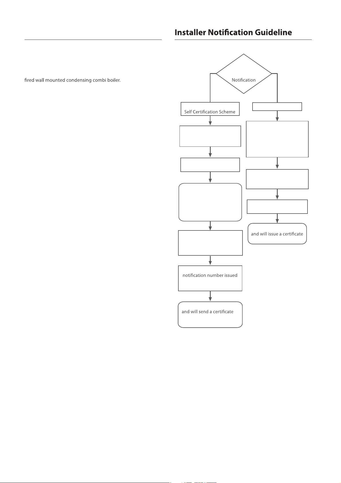
Regulations
Competent Person's
Install and Commission
this appliance to
manufacturer's instructions
Complete the Benchmark
Checklist
If you notify via Gas
Scheme, Gas Safe will then
notify the relevant Local
Authority Building Control
Scheme on member's
behalf
Choose
Building
Route
Building Control
Contact your relevant Local
Authority Building Control
(LABC) who will arrange
an inspection or contact
a government approved
inspector
Install and Commission this
appliance to manufacturer's
instructions
Complete the Benchmark
Checklist
Scheme Members only
Contact Gas Safe or visit
www.gassaferegister.co.uk
You must ensure that the
by Gas Safe is written onto
the Benchmark Checklist
Gas Safe will record the data
of compliance to the
property
LABC will record the data
of compliance
2
Preface
EHC

Contents
1. Safety Considerations 4
1.1 Saf et y Denition s
1.2 Symbols Used in the Instructions
1.3 Important Safety Precautions
1.4 Legislation
1.5 CE Marking Information
2. Product Description 6
2.1 Description
2.2 Layout and Key Components
2.3 Control Panel
3. Technical Data 8
3.1 General Specications
3.2 Hydraulic Data
4. Dimensions 10
5. System Details 11
5.1 Operation Modes
5.2 Safety Functions
6. Installation Requirements 13
6.1 Location
6.2 Required Minimum Clearances
6.3 Ventilation
6.4 Gas Supply
6.5 Electrical Supply
6.6 Water Supply
6.7 Condensate Drain
6.8 Flue
7. Flue Options 18
7.1 Calculating the Overall Length of the Flue System
7.2 Fitting the Concentric Flue System
7.3 Fitting the Separate Flue System
8. Installation Procedure 21
9. Transporting and Unpacking 22
9.1 Transporting the Appliance
9.2 Unpacking and Checking the Accessories
13. Connecting the Flue 28
13.1 For a concentric ue system
13.2 For a separate ue system
14. Electrical Connections and Settings 29
14.1 Accessing the Controller Assembly
14.2 Accessing All the Electrical Connections
14.3 Connecting to Mains Power 230V
14.4 Connecting the Controller, Accessories and External Controls
14.5 Ensuring the DIP Switch Settings
15. Final Check and Commissioning 33
15.1 Connecting the Power Cable and Turning the Power ON/OFF
15.2 Checking the Gas Settings
15.3 Checking the Gas Equipment for Soundness
15.4 Checking and Adjusting the CO
15.5 Installing the Front Cover
15.6 System Filling and Pressurising
15.7 Operational Checks
15.8 Final Commissioning Check
16. Instructing the End User 41
16.1 Handing over the Instructions
16.2 Showing How to Operate
17. Error Code List 41
18. Electrical 42
18.1 Wiring diagram
19. Parts List 43
19.1 Base Parts
19.2 Burner Parts
19.3 Water Way Parts
20. Appendix 47
Appendix 'A' Gas Conversion
Appendix 'B' Warranty Conditions
Appendix 'C' Commissioning Check List
Value
2
10. Mounting the Appliance on the Wall 23
11. Making the Gas Connection 24
11.1 Gas Piping Materials
11.2 When using LPG
11.3 Gas Supply Pipe Installation Procedures
12. Fitting the Water Pipes and Condensate Pipe 26
12.1 Water Pipes and Condensate Pipe Connection Procedures
12.2 General Pipework Connections
12.3 Water Pipe Size and Water Pressure
12.4 Pressure R elief Valve
12.5 Frost Protection
EHC
3Contents
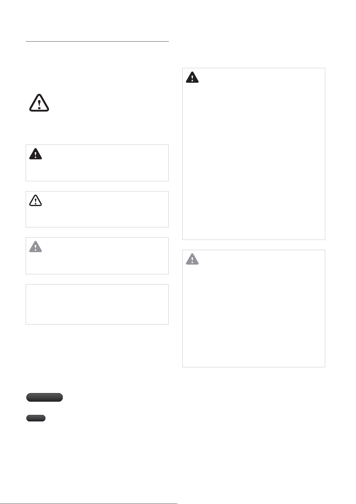
Safety Considerations1.
Safety Definitions1.1
All safety messages will refer to potential hazards. Precisely
follow the instructions to avoid the risk of injury.
This is the safety alert symbol. It is used to alert
you of potential personal injury hazards.
Adhere to all safety messages that follow this
Symbol to avoid possible injury or death.
List of safety symbols in the instructions
DANGER
Indicates an imminently hazardous situation which, if not
avoided, could result in severe injury or death.
WARNING
Indicates a potentially hazardous situation which, if not
avoided, could result in severe injury or death.
Important Safety Precautions1.3
DANGER
If you smell gas
Gas Leaks can cause explosions, which may
lead to serious injury..
Do not smoke. Prevent open ames and sparks.
Do not operate light switches or electrical equipment
switches.
Open the windows and doors.
Close the gas shuto valve.
Shut down the heating system.
Keep people away from the danger zone.
Observe the safety regulations of your local gas supplier,
found on the gas meter.
Notify your heating contractor from the outside of the
building.
Flue gas may lead to life-threatening poisoning.
Shut down the heating system.
Ventilate the location.
Close all doors leading to living spaces.
Do not operate electrical switches.
CAUTION
Indicates an imminently hazardous situation which, if not
avoided, could result in minor or moderate injury.
CAUTION
Used without the safety alert symbol indicates a potential
hazardous situation which, if not avoided, could result in
property damage.
Symbols Used in the Instructions1.2
The following symbols are used throughout the instructions to
bring attention to the important information concerning the
appliance.
Important
Note
Warns of a risk of material loss and
environmental pollution.
Indicates additional information that is
important but not related to personal injury
or property damage.
CAUTION
Working on the heating system
Isolate the system from the main electrical power supply, e.g.
by removing a separate fuse or by means of a main electrical
isolator, and check that it is no longer “live”.
Isolate the gas supply and safeguard it from unauthorized
reopening.
For propane appliances
Purging the liquid gas tank when installing the system:
Before installing the appliance make sure that the gas tank
has been purged. The liquid gas supplier is responsible for
properly purging the tank. Ignition ploblems may occur
if the tank is not bled properly. In such cases, frst contact the
person responsible for filling the tank.
Safety Considerations
4
EHC
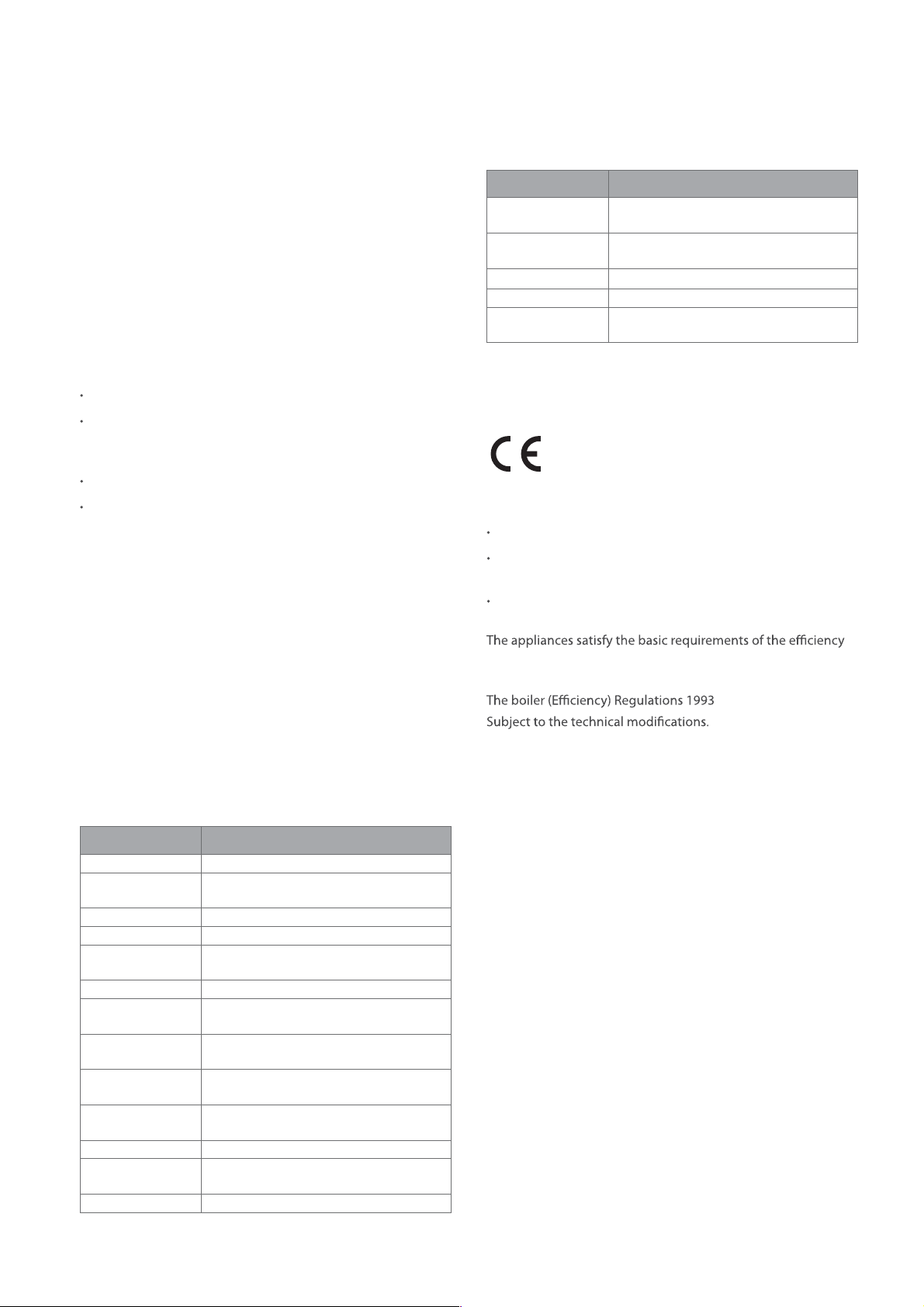
Legislation1.4
EHC Declares that this appliance is free of any harmful
substances, and no harmful substances are used during
appliance manufacturing.
The appliance is suitable only for installation in GB and should
be installed in accordance with the rules in force, and only used
in a suitably ventilated location.
In GB, the appliance must be installed and commisioned by a
GAS SAFE Registered Installer.
The appliance must be installed also in accordance with the
relevant requirements of the:
Gas Safety (Installation & Use) Regulations.
The appropriate Building Regulations : either one of The
Building Regulations, The Building Regulations (Scotland) , or
The Building Regulations (Northern Ireland).
The Water Fittings Regulations or Water Byelaws in Scotland.
The Current I.E.E. Wiring Regulations.
For detailed information on the installation of condensing
boilers, reference should be made to the ODPM Guide to the
Condensing Boiler Assessment Procedure for Dwellings.
Standard Scope
BS 7074 Expansion vessels and ancillary
equipment for sealed water systems
BS 7593 Treatment of water in domestic hot
water central heating systems
BS 7671:2008 Requirements for electrical installations
BS EN 303-7:2006 Heating boilers
BS EN 483 Type C Boiler of nominal heat input not
exceeding 70 kW
CE Marking Information1.5
0051
The appliance complies with the basic requirements of the
relevant European directives.
Gas appliances directive (90/396/EEC)
Electromagnetic compatibility directive with threshold class B
(89/336/EEC)
Low voltage directive (73/23/EEC)
C.O.S.H.H.
Materials used in the manufacture of this appliance are
Non hazardous and no special precautions are required when
servicing.
Codes of Practice - refer to the most
recent version
Installation should also comply with the following British
Standards Codes of Practice:
Standard Scope
BS 1212-1:1990 Float operated valves
BS 4814:1990 Specication for expansion vessels using
an internal diaphragm
BS 5440 Part 1 Flues
BS 5440 Part 2 Ventilation
BS 5546 Installation of hot water supplies for
domestic purposes
BS 5449 Forced circulation hot water systems
BS 5482-2:1977 Domestic butane- and propane-gas-
burning installations
BS 6281-1:1992 Devices without moving parts for the
prevention of contamination of water
BS 6282-2:1992 Devices with moving parts for the
prevention of contamination of water
BS 6283-4:1991 Safety and control devices for use in hot
water systems
BS 6798 Installation of gas red hot water boilers
BS 6880-1:1988 Title code of practice for low
temperature hot water heating systems
BS 6891:2005 Gas Installation
directive (92/42/EEC) as condensing boilers.
The Gas Appliance (Safety) Regulations 1992
As a result of our policy of constant development, there may
be small diferences between illustrations, functional steps and
technical data.
EHC
5Safety Considerations
Product Description2.
Description2.1
EHC Ecosave condensing gas boiler is a fully automatic, wall
hung, fan assisted balanced ue condensing boiler for use with
Natural Gas and Propane Gas. For gas type conversions see the
Appendix on Page 39.
This appliance is fully modulating and provides central heating
and domestic hot water. The following four models are available
according to their maximum outputs.
Model
EHC Ecosave-21K(A)
EHC Ecosave-25K(A) 23.1 kW 23.1 kW
EHC Ecosave-32K(A) 29.5 kW 34.2 kW
EHC Ecosave-37K(A) 34.2 kW 34.2 kW
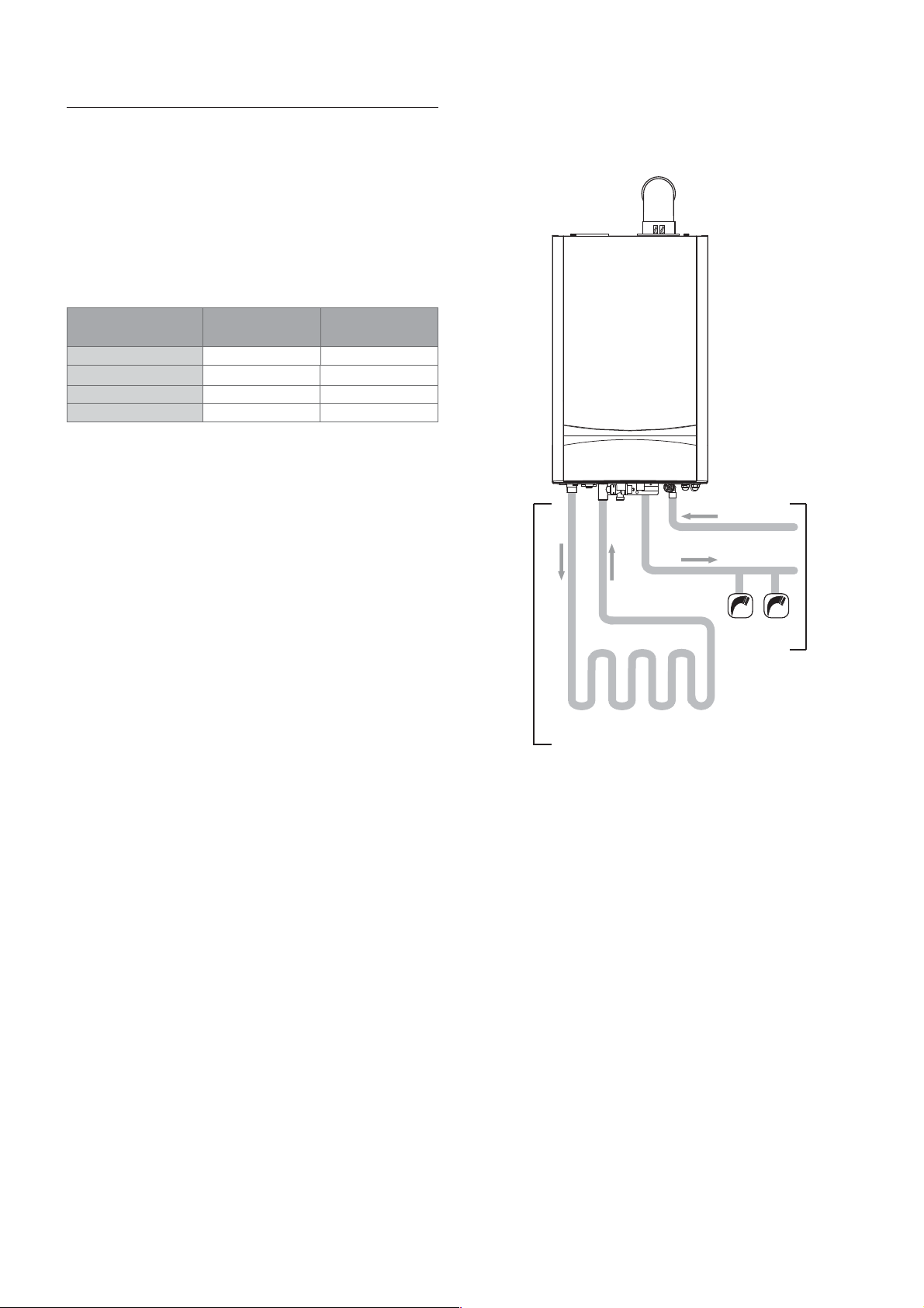
The appliance always gives priority to DHW supply.
The appliance is designed to be used with a circulation pump,
a divert valve assembly, a ow sensor, a DHW plate heat
exchanger, a safety valve, and a CH expansion vessel. A separate
DHW expansion vessel is not required.
Internal frost protection and an electronic control unit are
incorporated within the boiler. Any volt free room thermostat
can be used with the boiler.
Maximum
Heating Output
19.3 kW 23.1 kW
Maximum
DHW Output
Central
Heating
(CH)
CH
ow
CH
return
Cold water
Domestic
hot water
Hot water tap
Domestic
Hot Water
(DHW)
Floor Heating Circuit or
Heating Circuit (Radiator)
Product Description
6
EHC
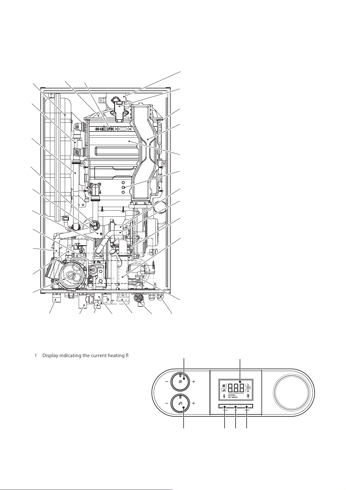
Layout and Key Components2.2
27
1
2
3
4
5
6
7
8
9
29
30
28
12
26
25
24
23
22
21
20
1 Expansion vessel
2 Heat exchanger & latent heat exchanger pipe
3 Heat exchanger outlet
4 Water pressure sensor
5 Air inlet
6 DHW
7 Gas control valve
8 Heat exchanger inlet
9 Magnetic Filter
10 Circulation pump
11 Flow
12 burner
13 Return
14 Pressure Relief
15 Gas Inlet
16 DHW outlet
17 Mains Water In
18 Cable Entry
19 DHW Flow
20 Condensate Syphon
21 Air Pressure Sensor
22 Gas
23 Gas/Air Mix
24 Latent Heat
25 Primary Heat
26 Mixing Flow
27 Exhaust
28 Electronic Ignition
29 Burner Mixing
30 Ignition
10
11
13
14
Control Panel2.3
temperature, the pressure in the heating
system, the operating mode and additional
functions.
2 CH temperature control knob
3 DHW temperature control knob
4 [MODE] button
5 [main ON/OFF] button
6 [RESET ] button
15
ow
16
17
19
18
12
3 654
EHC
7Product Description
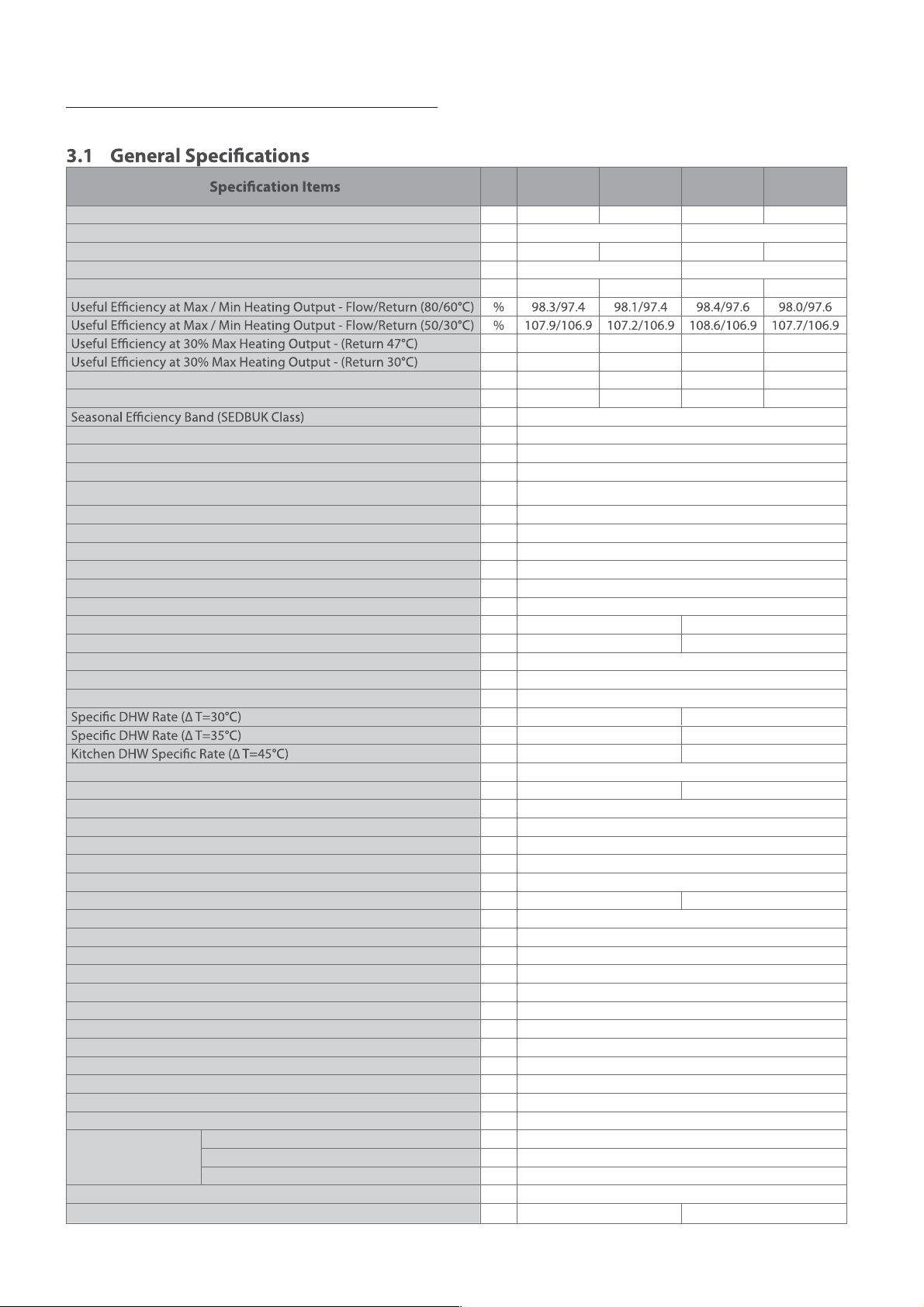
Technical Data3.
Unit
Heat Input (Max/Min) kW 19.6/4.9 23.5/4.9 30.0/7.0 34.9/7.0
Domestic Hot Water Input (Max/Min) kW 23.5/4.9 34.9/7.0
Heating Output (Max/Min) - Flow/Return (50/30°C) kW 19.3/4.8 23.1/4.8 29.5/6.8 34.2/6.8
Domestic Hot Water Output (Max/Min) kW 23.1/4.8 34.2/6.8
Condensing Heating Output (Max/Min) - Flow/Return (50/30°C) kW 21.1/5.2 25.2/5.2 32.6/7.5 37.6/7.5
Heat Loss through the Case with Burner On % 0.1 0.1 0.1 0.1
Heat Loss through the Chimney with Burner On % 1.6 1.8 1.5 1.9
NOx Class 5
Category II2H3P
Purpose Heating and Domestic Hot Water Production
Heating Adjustability Range Rated
Heating Water Circulation Method Air Close Type
Max Heating Water Pressure bar 3
Max Heating Temperature °C 85
Adjustable Temperature Heating Setting °C 30 - 85
Total Volume Expansion Vessel L 6.5
Expansion Vessel Pre-charge bar 1
DHW Output kW 23.1 - 4.8 34.2 - 6.8
Min. Dynamic DHW Pressure bar 0.3
Min. DHW Flow Rate l/min 2.5
Max. DHW Pressure bar 10
Adjustable DHW Temperature °C 30 - 65
l/min 11.7 17.6
l/min 10.0 15.1
l/min 7.8 11.7
Electrical Supply V/Hz 230 / 50
Nominal Absorption A 0.6 0.62
Power Consumption W 130
Electrical Protection IPX5D
Installation Type Wall Mounting Type
Intake/Exhaust Flue System Type B23-B33-B53-C13-C33-C43-C53-C63-C83
Intake/Exhaust Flue Diameter mm Concentric 60/100 – Separate 80/80
Max. Flue System Resistance Pa 167 294
Max. Horizontal Coaxial Ø60/100 Flue length (EHC System) m 20
Max. Vertical Coaxial Ø60/100 Flue length (EHC System) m 21
Equivalent Length of Ø60/100 Bend 90° m 1.3
Equivalent Length of Ø60/100 Bend 45° m 1
Max. Horizontal Coaxial Ø80/125 Flue length (EHC System) m 68
Max. Vertical Coaxial Ø80/125 Flue length (EHC System) m 70
Equivalent Length of Ø80/125 Bend 90° m 2.2
Equivalent Length of Ø80/125 Bend 45° m 1
Equivalent Length of Ø60/100 => Ø80/125 Adapter m 0.5
Max. Horizontal Separate Ø80-Ø80 Flue length (EHC System) m 110
Equivalent Length of Ø80 Bend 90° m 2.2
Equivalent Length of Ø80 Bend 45° m 1.4
Heating Water Connection mm 22
Connecting Diameter Domestic Hot and cold Water Connection mm 15
Gas Inlet Connection mm 22
Physical dimensions (Width × Depth × Height) mm 440 × 370 × 695
Technical Data
8
Ecosave
21K(A)
% 100.7 101.6 101.8 101.9
% 109.6 108.4 108.4 108.3
gkWeight 35 38
Ecosave
25K(A)
A
Ecosave
32K(A)
Ecosave
37K(A)
0.5
EHC
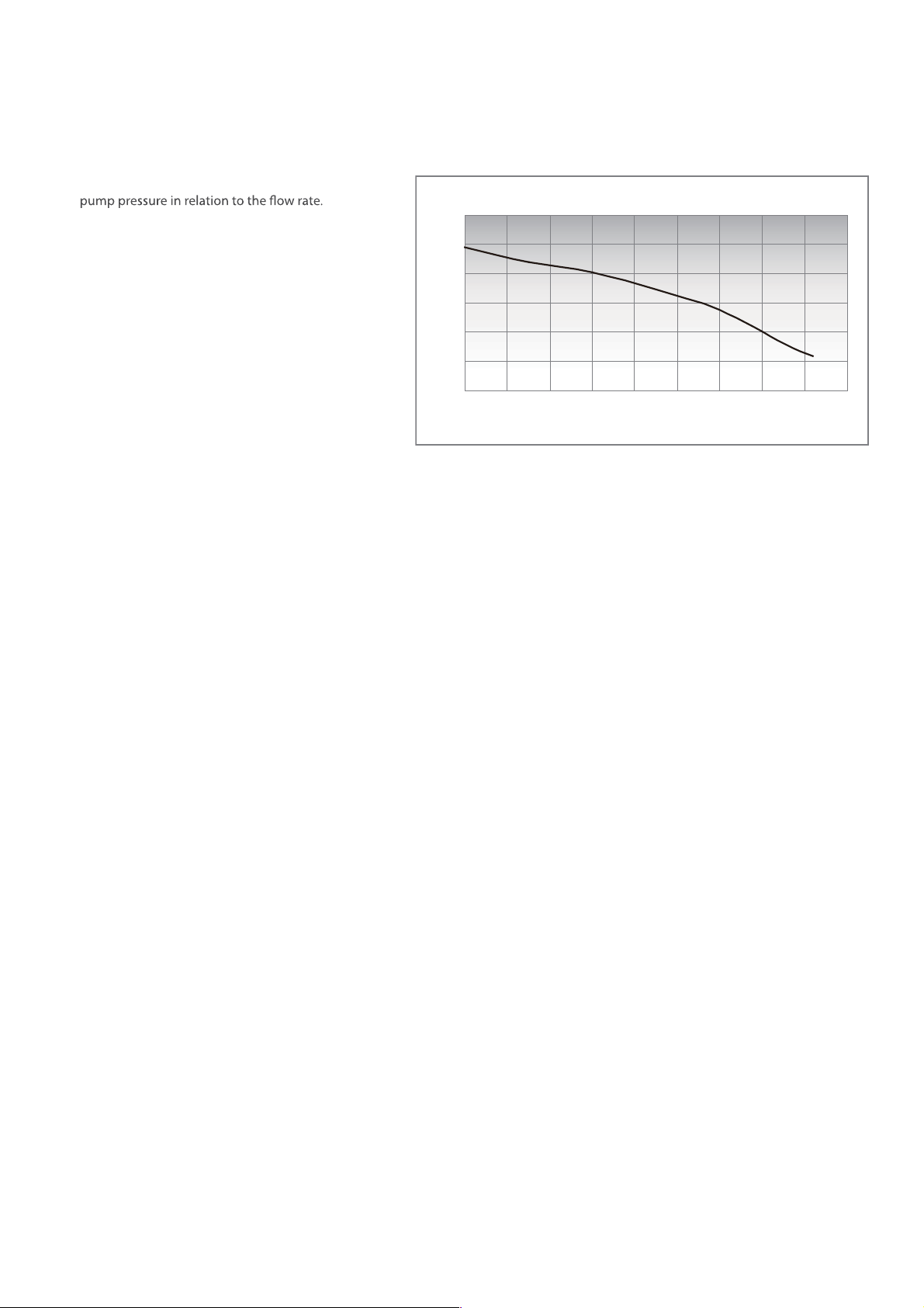
Hydraulic Data3.2
The following graph shows the development of the
Available Head Pump to the System
600
500
400
300
Head (mbar)
200
100
0
0 200 400 600 800 1000 1200 1400 1600 1800
Heating Flow Rate(l/h)
EHC
9Technical Data
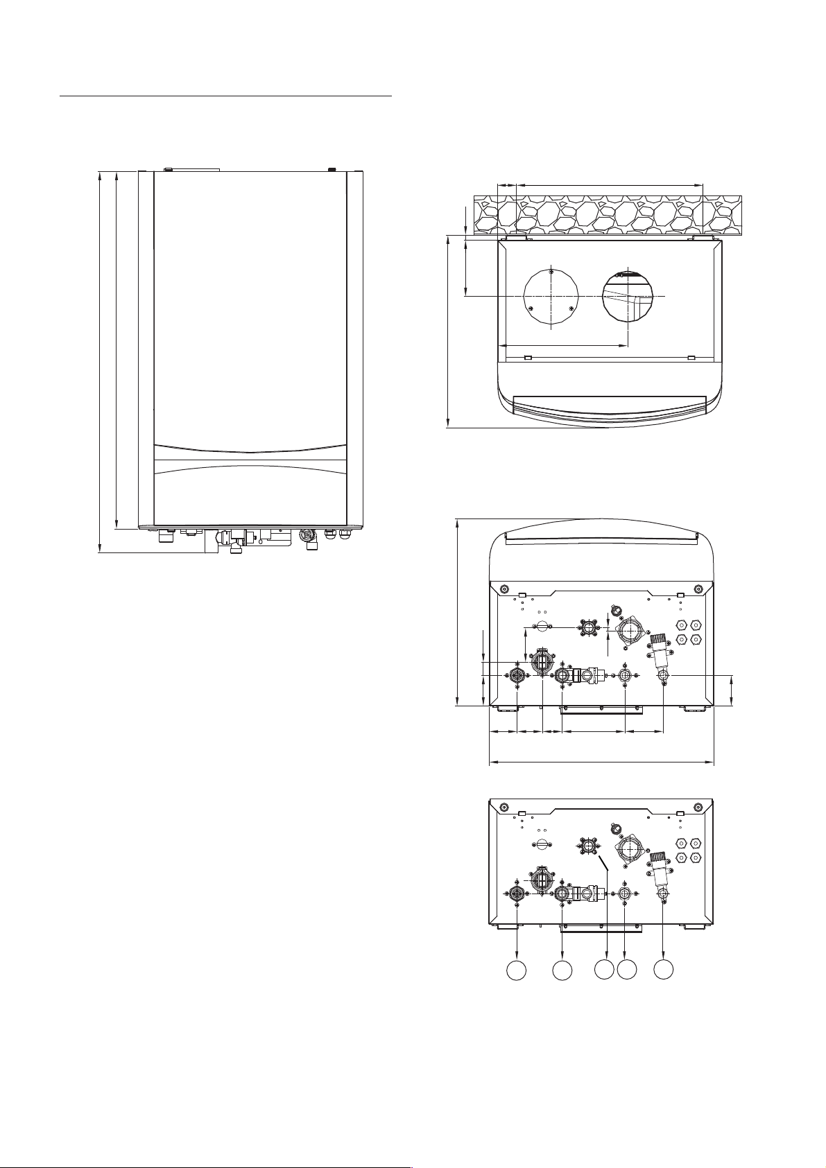
Dimensions4.
698.8
745.7
Front view
110.4
376.3
10
Overhead view
37
255
Bottom view
366
All dimensions in mm
366.3
67.5
25.5
60
49.2
55
39.1
ABC E
6.1
122.5
440
D
60.4
75
10
Dimensions
A: Heating outlet 22mm
B: Heating inlet 22mm
C: Gas inlet 22mm
D: DHW outlet 15mm
E: Main water inlet 15mm
EHC
System Details5.
Operation Modes5.1
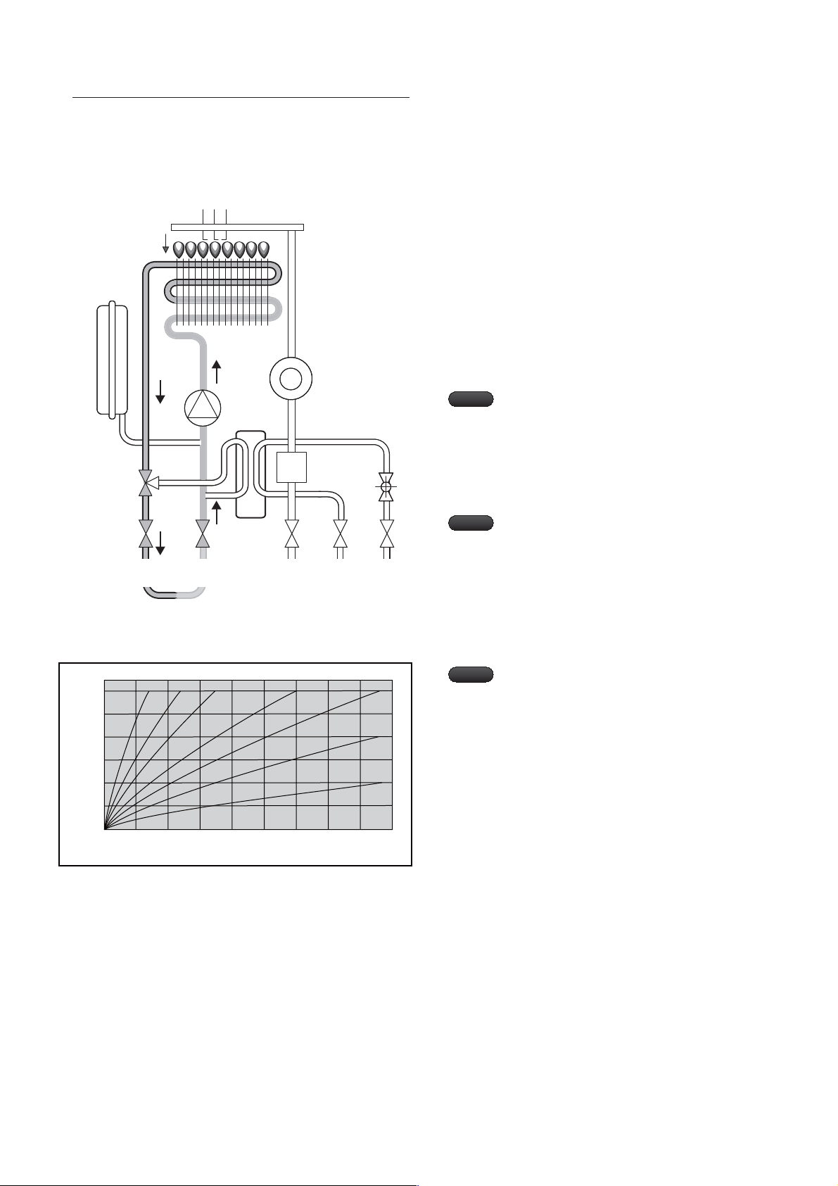
Circuit for CH (central heating) mode
Expansion
Vessel
Three-way
Valve
Ignition
Electrode
CH
Flow
CH
Return
Flame Sensing
Electrode
Heat
Exchanger
Circulation
Pump
Metal Fibre
Burner
Mixing Flow
Guide
Gas
Inlet
Blow Fan
Gas Valve
When central heating is in demand, the three-way valve1.
is set to CH mode position.
When the burner has ignited and the flame is detected,2.
the control starts heating up the CH water to the set
temperature. This control regulates the gas input rate by
changing the fan speed.
The pump runs from 0 to 600 seconds depending on the
3.
set temperature.
Note
Low water pressure error
cancelling function
If the water pressure falls below 0.4 bar, the low
water pressure error occurs on the control panel.
In this event re-pressurise the boiler to 1.5 bar
Note
The minimum operating
pressure can be adjusted in the
service menu.
80.0
70.0
60.0
50.0
40.0
30.0
Target primary temperature
20.0
20
15 10 5 0 -5 -10 -15 -20 -25
Outdoor Temperature (°C)
Relationship between primary and outdoor
K=1.5K=6 K=4 K=3 K=2
K=1
K=0.5
temperature: K-factor
Note
Weather Compensation
If an outdoor temperature probe is connected,
the weather compensation function can be used.
With this function, the target primary temperature
is automatically set according to the outdoor
temperature (K-factor).
Note - The control panel enables you to adjust
the parameters by resetting the K-factor.
EHC
11System Details
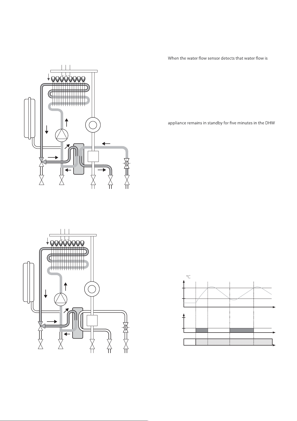
Circuit for DHW (Domestic Hot Water) mode
Expansion
Vessel
Ignition
Electrode
Flame Sensing
Electrode
Heat
Exchanger
Circulation
Pump
Metal Fibre
Burner
Mixing Flow
Guide
Blow Fan
1.
in demand by a tap or shower, the three-way valve
is set to DHW mode position as priority is given to the
DHW mode.
The primary water circulates through the DHW Heat 2.
Exchanger, and the water coming from the inlet is
heated.
The heating control function controls the burner until the 3.
DHW reaches the set temperature.
After DHW is used, the burner is extinguished and the 4.
three-way valve remains in the DHW mode position. The
mode.
When CH is demanded, the position of the three-way 5.
valve is changed to the CH mode position, and the system
returns to the CH mode.
Three-way
Valve
DHW Pre-heating mode
Ignition
Electrode
Expansion
Vessel
Heat
Exchanger
Three-way
Valve
DHW Heat
Exchanger
Flame Sensing
Electrode
Circulation
Pump
DHW Heat
Exchanger
Gas Valve
Gas
Inlet
Metal Fibre
Burner
Mixing Flow
Guide
Blow Fan
Gas Valve
DHW Water
outlet Inlet
Water
Flow
Sensor
If the CH mode is not used and the service setting for the DHW
pre-heating mode is set to ON, the DHW pre-heating mode
can be used.
The primary water circulates through the DHW Heat 1.
Exchanger. This pre-heats the unit in preparation for
DHW demand.
The burner is ON or OFF depending on the return 2.
temperature so that the set temperature is maintained.
Return Temp (°C)
Toff
Ton
Burner operation
MAX
MIN
DHW
pre-heating
mode
ONOFF
Time
System Details
12
Gas
Inlet
EHC
Installation Requirements6.
Safety Functions5.2
Frost Protection
In CH, DHW, and Weather Compensation modes, frost protection
is an integral function for protecting the appliance. This function
is the highest priority among the operation modes and this
There are two kinds of processes depending on the primary
water temperature.
6 -10°C
If the primary water temperature falls below 10°C, the control
system runs the pump for 10 minutes and stops the pump for
1 minute. This process is continued while the primary water
temperature is in the above mentioned range.
Below 6°C
The appliance ignites the burner in the CH mode until the
primary water temperature reaches 21°C.
High Temperature Protection (HTP)
In stand-by and while the burner is operating, if the High
pump and the fan start in order to reduce the temperature of
the appliance. The pump and the fan continue to run in the CH
mode until the primary water temperature falls below 80°C.
While the burner is operating, the safety shut-down process
takes place. At this point the pump and the fan re-start.
Actuator Protection
If the appliance is not operated for 24 hours, the fan and pump
automatically operate for 30 seconds to prevent seizing.
Location6.1
DANGER
The appliance must be tted to a suitable wall to prevent re
and explosion. At the installation site, the ue that passes
through the outside wall or roof must be routed properly
in order to satisfactorily remove flue products. Also, an
adequate air supply must be provided, and combustible
products need to be removed.
Do not t the appliance near paper, newspapers, magazines,
or any other combustible objects.
Do not t the appliance where rubbish is located.
WARNING
If the appliance is tted in a room with high humidity (e.g.
a room containing a bath or a shower), the appliance and
any electrical switch or appliance controller, etc. should
be situated specically in accordance with the current IEE
Wiring Regulations and Building Regulations.
If the appliance is tted into a building made of timber
frames, refer to the latest edition of the Institute of Gas
Engineers Publication IGE/UP/7 (Gas Installations in Timber
Framed Housing) or British Gas Document DM2 and DM3.
The appliance should not be ftted in the building unless it is
protected by an appropriate enclosure, such as a garage or
outbuilding. (The appliance may be tted inside a cupboard).
For other unusual locations, refer to BS 6798:2000 for
detailed guidance.
Note
Fit the appliance at an appropriate height.
Air Flow Checking
During the start-up sequence, the “no air check” function
supply.
EHC
13Installation Requirements
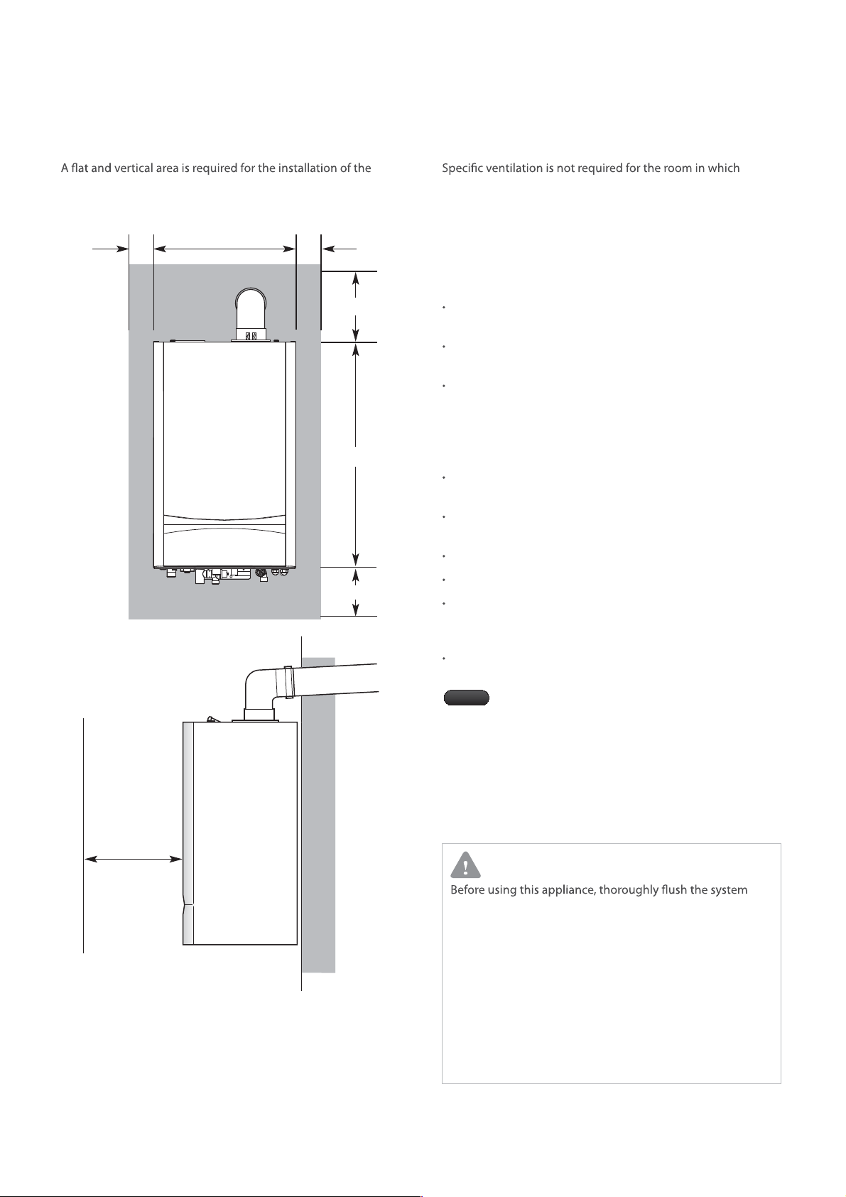
Required Minimum Clearances6.2
Ventilation6.3
appliance. The following minimum clearances (mm) must be
maintained for installing and servicing.
5 mm
440 mm
5 mm
250 mm
698.8 mm
200 mm
the appliance is installed. If it is installed in a cupboard or
compartment, permanent ventilation for cooling purposes is
not required. Detailed recommendations are given in BS 5440
Part 2.
Gas Supply6.4
Gas installation must comply with the requirements in BS
6891.
Check for leaks at every joint as described in BS 6891 to
check the soundness.
Ensure that the pipe sizes, including the ones for other gas
appliances on the same supply, are adequate for demand.
Electrical Supply6.5
Main supply : 230 V~/50 Hz with 3 Amp fuse certied BSI or
VDE.
Cable : PVC insulated 0.75 mm
rated to 90°C.
The appliance must be earthed.
All pipes to the appliance must be cross-bonded.
Wiring must comply with IEE Wiring Regulations and any
local regulations which may apply to a xed wired
stationary appliance.
External wiring must be correctly earthed, polarized and
must comply with related regulations/rules.
Note
The way the electricity supply is connected must
facilitate the complete electrical isolation of the
appliance. It may be connected via a fused doublepole isolator with a contact separation of at least
3 mm for all the poles for servicing the appliance
and system controls only.
2
(24 × 0.2 mm) temperature
600 mm min
Case
Removal
Purposes
These dimensions include the necessary clearances around the
appliance for case removal, spanner access and air movement.
Additional clearances may be required for the passage of pipes
around local obstructions.
Installation Requirements
14
Water Supply6.6
CAUTION
(ensure the appliance is not connected) to remove any sediment
and prevent the heat exchanger from being damaged by
build-up or corrosion due to any sediment.
Do not use petroleum-based cleaning and seals because
the system may be damaged and may result in substantial
property loss.
Immediately repair leaks in the appliance or piping in order
to prevent the build-up of mineral and corrosion in system
components due to the continuous water make up.
The build-up of minerals and corrosion will reduce the life
of the appliance.
EHC

Condensate Drain6.7
General instructions
Important
Note
This appliance is a high eciency gas appliance that
creates condensate when operating. The condensate must
be discharged in accordance with any national or local
regulations in force since the condensate has an acidity (pH)
of approximately 3 - 4 (BS 6798:2000 & Part H1 of the Building
Regulations give further guidance).
A condensate trap is built into the appliance as standard.
Options for the condensate drain (see the gures on the
next page).
From the appliance to the drain/gully via a sink waste1.
(the bottom of the appliance must be above the top of the
sink and must be downward-sloping to properly discharge
condensate)
From the appliance to the internal soil and vent stack2.
From the appliance to a soakaway hole surrounded by 3.
limestone chipping
From the a4.
Of the above options, EHC recommends option 1 as the soap
from the sink neutralizes the acidic condensate.
If a sink waste is not abilable, EHC recommends options 2, 3, or
4. If permitted by local regulations, the condensate may
be drained directly into the drain/gully.
Note
If a soakaway hole is installed, periodical
replacement of the limestone chipping (or
neutralizing agent) is required. The rate of depletion
of the limestone varies depending on the usage
of the appliance. Occasionally check the depletion
of the neutralizer, and replace the limestone if any
depletion is observed.
The condensate must be drained from the
appliance in accordance with applicable
rules and regulations.
Reliable operation of the appliance will
be afected by an improperly connected
condensate piping.
The condensate pipe must retain a
downward slope of at least 2.5 degrees
throughout.
ppliance to the drain/gully
CAUTION
Requirements for the condensate piping are as follows.
So that condensate can be properly drained the t
diameter of the plastic piping should be a minimum of
22 mm.
The condensate pipe should be made of a non-corrosive t
material, such as PVC, PVC-U, ABS, PVC-C or PP. Metal
materials are NOT suitable.
For safety reasons the ends of the pipes should extend t
as close as possible to the ground or drain/gully.
To reduced the risk of the condensate becoming trapped
as few elbows and fttings as possible should be used.
When draining the condensate into an internal soil and t
vent stack, the plumbing eect must be considered.
If the pipes are easily aected by internal pressure
uctuations, when WC's are ushed or sinks are emptied,
back-pressure may force water out of the appliance trap
and a lockout may occur.
The length of the external pipework should be kept to t
a minimum and routed as vertically as possible. Where
the pipework is subjected to extreme cold or windchill,
weatherproof insulation should be used. If insulation is
not used then the condensate pipework should have a
minimum diameter of 32 mm.
For 22 mm diameter condensate drainage pipe, the t
maximum length is 3 metres.
If the appliance is tted in an unheated location, the t
entire pipe system should be treated as an external run.
In order to prevent sagging, any external runs need to t
be propped up with supporting clips.
EHC
15Installation Requirements
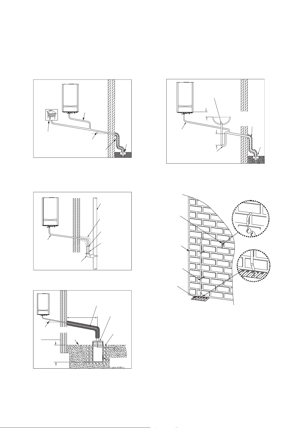
Examples of available options for
condensate drain
1. From the appliance to the drain/gully via a sink
22 mm plastic
condensate
pipe
sink
2.5º minimum drop
Frost proof insulation
(if necessary)
The end of the pipe must be above water level
*
but below the surrounding surface.
2. From the appliance to the external rain water pipe into
foul water
External rain water
pipe into foul water
Internal soil
and vent stack
Drain/Gully
4. From the appliance to the gully
Visible air break
at pulg hole
Sink with
integral
100mm
overow
22 mm plastic
condensate pipe
75 mm
min.
75 mm sink
waste trap
The end of the pipe must be above water level
*
but below the surrounding surface.
Condensate drain termination
PRV
Frost proof
insulation
(if necessary)
Drain/Gully
Extarnal air break
22 mm plastic
condensate pipe
running through
the external wall
43 mm 90°
M &F bend
3. From the appliance to a soakaway hole surrounded by
limestone chipping
22 mm plastic condensate
drainage pipe, max extarnal
length 3 metres
500 mm min.
2.5º minimum drop
Hole depth
400 mm min.
(by 300 mmΦ)
Holes in the soakaway must face away from the
*
building.
Ground
level
Air gap
68 mmΦ PVC-u
strap on fitting
100 mm Φmin.
sealed plastic tube
Limestone
chippings
25 mm
Drainage
holes
Outside wall
Condensate
pipe
External
drain
Installation Requirements
16
EHC
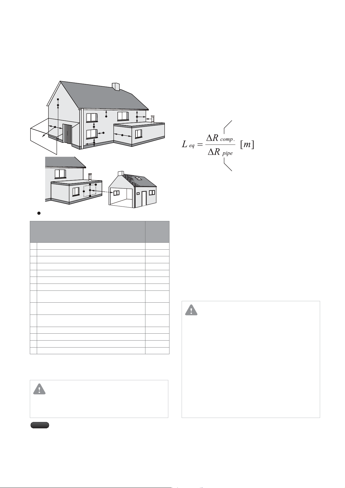
8.6eulF
The minimum distances between the terminals and elements of
the building are as per the following.
A
G
BCD
F
J
H, I
A
A
A
E
G
L
K
N
L
K
Use of terminal guards needs to be considered.
Description
A
From openings (e.g. doors, windows, ventilation tiles)
B
Below gullies, down-pipes, or drain pipes
C
Below gutters
D
Below balconies
E
From down pipes
F
From external and internal corners
G
Above the ground, a roof or balconies
From the opposite wall of a carport (when another
H
ue is not installed)
From a terminal, that is facing the terminal, on the
I
opposite wall of a carport
Next to openings (e.g. doors, windows) within a
J
carport
K
Vertically away from a terminal on the same wall
L
Horizontally away from a terminal on the same wall
M
From an adjacent vertical ue pipe
N
From openings in a directly opposing building
*1 The terminal should not be located within 15 cm from openings
in the building material made for a built-in object (e.g. window
frame)
*2 This length is according to BS 5440-1.
CAUTION
Terminal guards must be provided for any terminals which are
located less than 2 metres above a balcony, above a at roof, or
above ground which people can access.
B
F
M
G
F
F
Minimum
Distance
(cm)
30(*1)
7.5
20
20
2.5
30
30
60
120
120
150
30
50
200(*2)
Formula of Length Equivalency
This is the formula for sizing the pipes for the intake of the
combustible air and the discharge of the combustion products.
The Length equivalency (L eq) in these instructions are for the
lengths of the pipes which share the same cross-sectional
dimensions.
Resistance of the component
under standard condition
Resistance of a 1-metre-long pipe
(with pre-established diameter)
under standard condition
Standard conditions are experimental values for the
capacities, fume temperature and air temperature for various
thermal power values. They represent dierent operating
conditions.
Example of coaxial system calculations
Planning the system run.1.
Measuring the length of the system run.2.
Determining the values of the length equivalency for all 3.
components.
Calculating the value of the total length.4.
Comparing the values with the maximum permissible 5.
length.
CAUTION
The wall on which the intake/exhaust ue is set must be
made of incombustible interior materials and must connect
to the outside. Dangerous materials or obstructions must
not be near the intake/exhaust ue.
The exhaust ue should be covered with over 20 mm of
incombustible material when it passes through a wall made
of combustible material and must be kept at least 50 mm
away from any combustible materials.
Connection parts of the exhaust ue must be properly
connected by proper sealing gasket. Check for any exhaust
gas leaks.
Before cleaning the intake/exhaust ue, turn o the
appliance and wait until the pipes have cooled down.
Safeguard the ue terminals from snow buildup.
Note
EHC
For vertical ue pipes, the terminal must not be t
within 60 cm of any openings
17Installation Requirements

Flue Options7.
Calculating the Overall Length of the 7.1
Flue System
These ue systems may be oriented in all the various directions
of the compass, north, south, west and east. Some special
components such as concentric bends are used so that
certain positions can be reached. Each concentric ue system
kit includes an adapter, which allows the appliance to be
connected to the ue system.
However, the total ue length cannot exceed the prescribed
maximum ue length. If concentric bends are required, please
bear in mind that each of them has resistance that corresponds
to its specic linear length.
There are 2 separate connections (horizontal and vertical) for
the concentric ue system and separate ue system.
Study the following connection depictions to determine which
ue system is the most suitable.
Maximum Flue Length
Concentric
Flue
System
Separate
Flue
System
Diameter of
Pipe [mm]
Φ 60/100
Φ 80/125
Φ 80/80
Orientation
Horizontal 20
Vertical 21
Horizontal 68
Vertical 70
Horizontal
Vertical
Maximum Flue
Length [m]
110
Fitting the Concentric Flue System7.2
Concentric Horizontal Flue
a) Standard ue system (Φ 60/100 mm)
”A” is the combined length of the ue outlet/
ventilation pipe maximum 20 m.
A
B 500 or 1,000
851
“B” is the ue outlet/ventilation pipe
(can be shortened as necessary).
Standard ue system: A = 20 m
b) Extended ue system (Φ 60/100 mm)
140 min
Wall
Reduced Flue Length
Diameter of
Pipe [mm]
Φ 60/100 - >
Φ 80/125
Concentric
Flue
System
Separate
Flue
System
Note
Φ 60/100
Φ 80/125
Φ 80/80
The adapter for Φ 60/100 mm ues or Φ 80/125 mm
ues is 0.5 m.
Angle
- 0.5
45° 1.0
90° 1.3
45° 1.0
90° 2.2
45° 1.4
90° 2.2
Reduced Flue
Length [m]
B
A
Total ue length: A + B – (1 x 90° elbow)
= 20 – 1.3 =18.7 m
18
Flue Options
EHC

Concentric Vertical Flue
A
B
Standard ue system : A = 21 m
Φ 60/100 mm)
b) Extended vertical ue system (Φ 60/100 mm)
A
Minimum 350 mm
B
Total ue length :
A + B – (2 x 45° elbow) = 21 – 2 x 1 = 19.0 m
Diameter of
Pipe [mm]
Φ 60/100
Φ 80/125 70
Grey coloured numbers are used in the calculation of
this sample.
Max Flue
Length [m]
21
(a/b)
Reduced Flue
Length [m]
45°
90° 1.3
45° 1.0
90° 2.2
1.0
(b)
EHC
19Flue Options

Fitting the Separate Flue System7.3
4
Separate Horizontal Flue
Extended separate horizontal fue system
(Φ 80/80 mm)
D
E
A
Total ue length:
A + B + C + D + E + F – (4 x 90° elbow)
= 110 – 4 x 2.2 = 101.2 m
Diameter of
Pipe [mm]
Φ 80/80
Grey coloured numbers are used in the calculation of this
sample.
B
Max Flue
Length [m]
110
(a/b)
F
C
Reduced Flue Length [m]
45° 1.4(a)
90° 2.2
Separate Vertical Flue
A
Total ue length:
A + B + C + D – (2 x 45° elbow) = 110 – 2 x 1.4 = 107.2 m
Diameter of
Pipe [mm]
Φ 80/80
Grey coloured numbers are used in the calculation of this
sample.
D
C
B
Max Flue
Length [m]
110
(a)
Minimum 350 mm
Reduced Flue Length [m]
2.2
(a)
.
45° 1.4
90°
Flue Options
20
EHC

Installation Procedure8.
*GUIFøVFTBSFOPUöUUFECFGPSFUIFJOTUBMMBUJPOPGUIFBQQMJBODF
Transporting and
Unpacking
section 9.
Mounting the Appliance
on the Wall
section 10.
(BTDPOWFSTJPO
*GOFDFTTBSZ
"QQFOEJY
Making the Gas Connection
section 11.
Fitting the Water Pipes and
Condensate Pipe
section 12.
Fitting the ues
t'JUUJOHUIFDPODFOUSJDøVFTFDUJPO
t'JUUJOHUIFTFQBSBUFøVFTFDUJPO
Connecting the Flue
TFDUJPO
Electrical connections
and Settings
section 14.
Final Check and
Commissioning
section 15.
Instructing the End User
section 16.
EHC
21Installation Procedure

Transporting and Unpacking9.
Transporting the Appliance9.1
CAUTION
The appliance may be damaged if it is not properly transported.
Transport the appliance using the right transportation t
equipment, such as a hand truck with a fastening belt or
special equipment for maneuvering steps.
Protect all parts against impact when they are t
transported.
Observe the transportation markings on the packaging.t
Packaged appliances must always be lifted and carried to
their destination by two people, or you must use a hand
truck or special equipment to transport them to their
destination.
Unpacking and Checking the 9.2
Accessories
Before actually installing, be sure to verify the gas supply, type,
pressure, and the electrical power supply.
Remove the boiler and accessories form the box.1.
Check the accessories inside the box.2.
The appliance is delivered fully assembled. After receiving
the delivery, check if the packaging is intact and all the items
listed below are included.
EHC Gas-Fired Wall Mounted Condensing Combination
Boiler
Wall Mounting Bracket
(including washers and
nuts)
User instructionst
Installation Instructionst
Tapping Screws & Anchors
(4 sets)
Flue Adapter
Condensate Drain Hose
Gas Conversion Kit
Transporting and Unpacking
22
EHC

Mounting the Appliance on the Wall10.
Mount the appliance on the wall using the following procedures.
Mark the installation points for the ues and screws on 1.
130
167
165
Boiler
mounting
plate.
Boiler
NOTE: Boiler will be 20cm higher
than mounting plate
the wall. Ensure that the points are both horizontally and
vertically level.
Make a hole for the ues (minimum diameter 116 mm).2.
Drive the supplied anchor bolts for the bracket into the 3.
marked points (minimum diameter 13 mm).
Fit the wall mounting bracket with the tapping screws and 4.
anchors.
Take great care when applying the boiler to the wall 5.
mounting bracket.
CAUTION
This appliance must always be lifted and carried by two
people.
Hook
EHC
23Mounting the Appliance on the Wall

Making the Gas Connection11.
WARNING
Before completing the gas pipe connection, ensure that
the type of gas is suitable for the appliance. If you use a type
of gas other than the one specied on the data plate on the
lower right corner of the appliance, it may cause incomplete
combustion and result in re or explosive ignition. Ensure
that the gas supplier supplies an adequate supply of gas. The
installation and connection of the gas supply to the boiler
must be in accordance with BS 6891.
When connecting a gas meter to the pipe,t
the gas meter must be connected to the pipe by a gas supplier or contractor only.
an existing meter should be checked to ensure that it is capable of measuring the required gas supply rate.
When tting the gas pipe, t
do not use pipes that are smaller than the boiler gas connection (22 mm).
pipes must be directly connected to the main pipe, they must not be connected to other gas appliances.
Gas Piping Materials11.1
WARNING
Installation pipes should be fitted in accordance with BS6891.
All pipework must be adequately supported.
An isolating gas valve is provided and should be fitted on the
boiler gas inlet. Please wait 10 minutes when lighting from
cold before checking the gas rate at the gas meter.
Gas pressure should be checked after the boiler has operated
for 10 minutes to reach thermal equilibrium.
When using LPG11.2
WARNING
If the boiler is used with LPG it must be connected to a
regulator. Connection and installation must conform to
BS 5482: Pt1 Domestic butane and propane gas burnig
installations.
DANGER
The complete installation must be tested for gas soundness
and purged as described in BS6891 as a gas leak may cause
serious injury or death.
If an appliance using LPG is installed in a room or internal
space below ground one side of the building must be open
to the ground.
Note
The outlet pressure regulated by the governor t
should be in accordance with BSEN-13785.
The diameter of the gas pipes for this unit is 22mm.t
See the specifications in these instructions.
DANGER
When using a gas container, place the container in a cool
shady place away from direct sunlight outdoors and fix the
container properly to prevent it from tipping over.
Othewise an explosion may occur.
Making the Gas Connection
24
EHC

Gas Supply Pipe Installation 11.3
Procedures
Connect the gas supply pipe to the gas inlet adapter 1.
located at the bottom of the appliance.
Check for gas leaks.2.
Valve kit for external connections.3.
Each boiler is supplied with an EHC Valve Kit for each external
connection. Please refer to the installation instructions within
the valve kit packaging.
DANGER
After completing installation, the gas pipes must be checked
for leaks and purged as described in the standards. Gas
leaks may cause an explosion that induces serious harm
or property damage. When purging, open all doors and
windows, and extinguish cigarettes, pipes or any other
naked lights.
EHC
Bottom view
Gas inlet adapter
25Making the Gas Connection

Union
Fitting the Water Pipes and Condensate Pipe12.
WARNING
Do not add anti-freez to the system as this may shortent
the life of the appliance and cause malfunctions.
Tighten the boiler connection valves with care to avoid t
Condensate Drain
Hose
damage.
Before using this appliance, thoroughly flush the system t
(ensure the appliace is not connected) to remove any
sediment and prevent the heat exchanger from being
damaged by build-up or corrosion due to any sediment.
Any contaminants inside the pipes may reduce heating
and hot water efficiency as well as causes malfunctions.
Any exposed pipes must be insulated with insulation t
material because they may freeze during winter. If hot
water cannot be used because the supply water in the
pipes freezes or because the water inside the heating
pipes is insucient, the water cannot be replenished. As a
result, the appliance may not function.
Do not use excessive force to connect the pipes. This t
might damage external parts and cause leaks.
CH ow
CH
return
Under Floor Heating Circuit or
Heating Circuit (Radiator)
Condensate Pipe
Bottom view
Cold Water
Supply
Hot Water Supply
Water Pipes and Condensate Pipe 12.1
Connection Procedures
Connect the water pipe to the water inlet adapter and 1.
DHW outlet adapter located at the bottom of the appliance
which is clearly indicated on the boiler.
Connect the water pipe to the heating supply adapter and 2.
to the heating return adapter that is located at the bottom
of the appliance which is clearly indicated on the boiler.
Connect the condensate drain hose which is clearly indicated3.
on the boiler. See Claus 6.7 Condensate Drain (How to drain
the condensate).
Condensate
Drain cock
Heating supply adapter
26
Heating return adapter
Fitting the Water Pipes and Condensate Pipe
outlet
Water Inlet
adapter
DHW outlet
adapter
EHC

General Pipework Connections12.2
Frost Protection 12.5
Refer to Code of Practice
BS7074:1 Domestic and hot water supply
BS6891 Installation of low pressure gas pipework up to
28mm(R1).
Copper pipework is the prefered material type.
If plastic pipework(barrier pipe) is used a minimum of 600mm
of copper pipe must be used from the boiler connection.
The discharge must not be above a window, entrance or
other pubic access. Consideration must be given to the
possibility that boiling water/steam could discharge from
the pipe.
The end of the pipe should terminate facing down and
towards the wall.
Water Pipe Size and Water Pressure12.3
The connection diameter of the cold water supply pipes for this
appliance is 15mm
To use the unit, the inlet pressure must be more than 0.5 bar
A water pressure of more than 1.0 bar is needed to supply
hot water to the second foor.
If the appliance is connected to a system that is potentially
frozen isolate the boiler's water and power supply.
The frost protection is an integral function to protect the appliance
in CH, DHW and OTC mode. This function has the highest priority
among the operation modes and this function works even if the
The Energy Saving 2 staged Frost Protection system protects both
inside the unit automatically operates to circulate water when the
water temperature for the heating falls below 10 *C. In the second
stage the boiler operates the burner when the temperature falls
below 6 *C.
All exposed pipework should be insulated to meet current standards.
When the boiler will not be used for long periods please observe
the following.
completely drain the water from the appliance to prevent
freezing.
isolate gas supply valve,
-
isolate the electrical supply.
-
If the appliance is installed in an extremely cold location, take
necessary measures, such as covering the exposed pipes and
electrics with insulation material.
Pressure Relief Valve12.4
The pressure relief valve is set at 3 bar, therefore all pipe
work, fttings, etc. should be suitable for pressures over 3 bar
and temperature in excess of 100°C.
The pressure relife valve should be connected to 15 mm copper
pipe. It should run continuously downward, and discharge
outside the building preferably over drains.
in such a manner that no hazard occurs to occupants or causes
damage to wiring or electrical components. The end of the pipe
should terminate facing down and towards the wall.
The discharge must not be above a window, entrance or other
pubic access. Consideration must be given to the possibility
that boiling water/steam could discharge from the pipe.
It should be routed
EHC
27Fitting the Water Pipes and Condensate Pipe

Connecting the Flue13.
WARNING
Adapter
The exhaust gas ducts must not come in to contact with t
or be located close to combustible materials and must not
pass through building structures or walls made of
combustible materials.
When replacing an old appliance, the ue system must be t
changed.
Adapter or connection methods vary depending on the type
of ue system (concentric type or separate type). Follow the
following instructions carefully.
For a concentric flue system13.1
Flue
Blanking plate
Air intake
Flue outlet
Each concentric ue system kit includes an adapter, as shown
in the gure, which helps connect the appliance to the ue
system.
Assemble the components and seals as shown in the gure.
Connect the ue adapter to the appliance.1.
connect the flue bend to the adapter and seal.2.
For a separate flue system13.2
Each separate ue system kit includes an adapter, as shown in
the gure, which helps connect the appliance to the ue system.
Assemble the components and seals as shown in the gure.
Flue Outlett
Install the ue adapter to the appliance.1.
Connect the flue bend to the adapter and seal.2.
Adapter
Connecting the Flue
28
Adapter
Flue
Air Intaket
Remove the blanking plate.1.
Connect the ue adapter to the appliance. (The adapter 2.
comes with this appliance.)
Connect the flue bend to the adapter and seal.3.
EHC
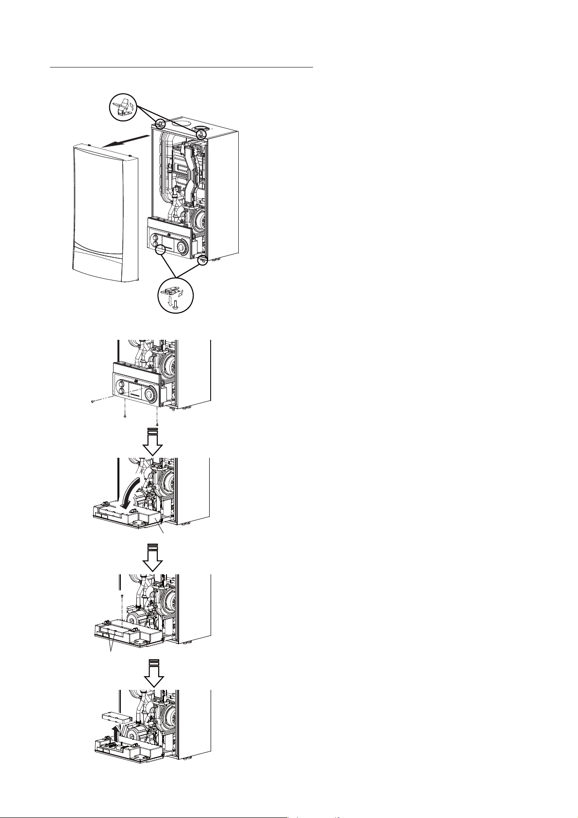
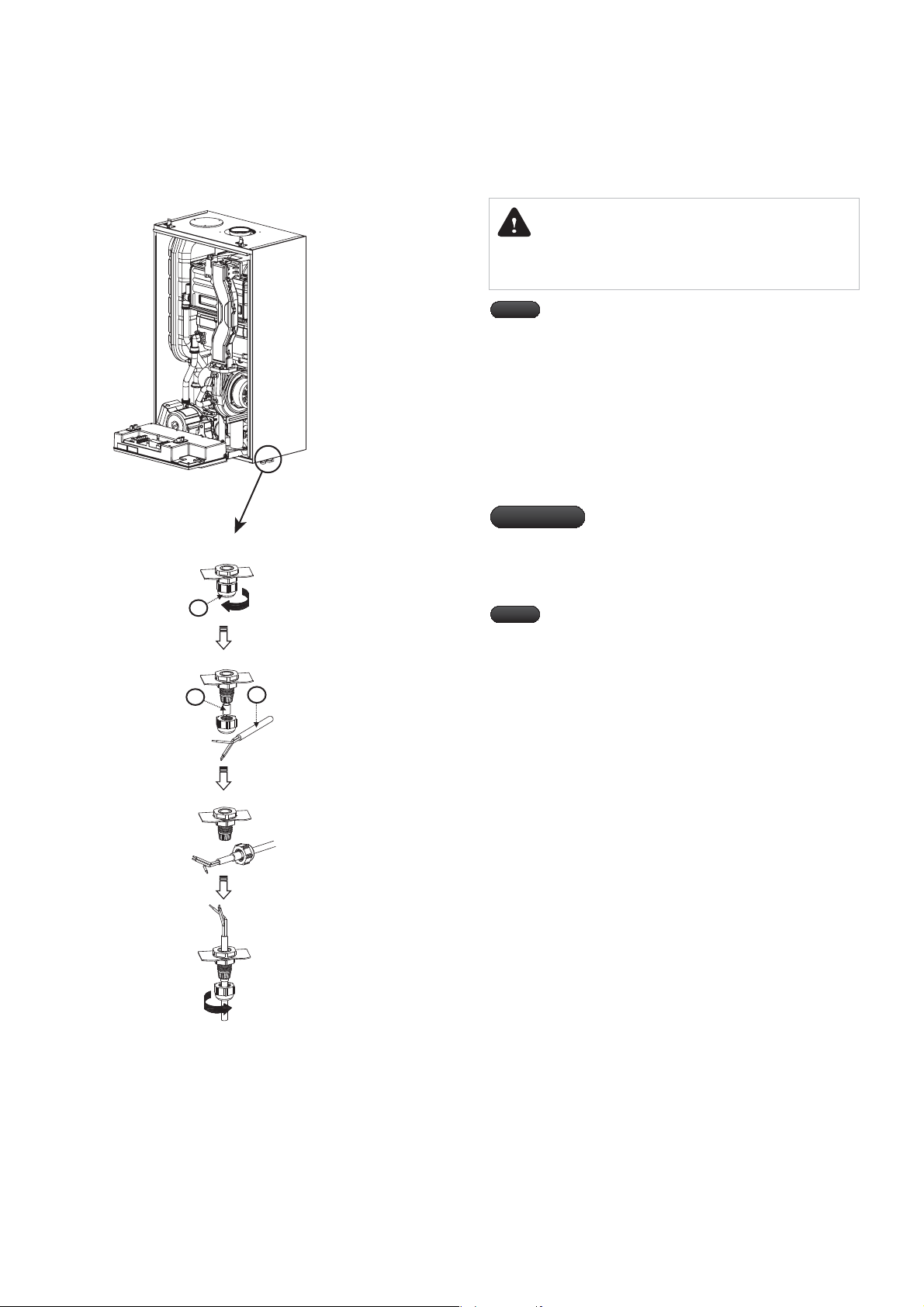
Electrical Connections and Settings14.
Accessing the Controller Assembly14.1
Remove the 2 screws from the underside of the appliance.1.
Unlatch all the clips, and pull up the hooks (2 on the top2.
and 2 on the bottom of the appliance).
Lift o the front panel from the wall mounted unit.3.
Remove the 3 screws on the underside of the controller assembly,4.
and 1 screw to the right of the controller assembly. Then pull
the controller assembly downward.
5. Remove the screw on the front of the controller cover, and then
the controller cover remove
EHC
Controller assembly
Clamp
29Electrical Connections and Settings
Accessing All the Electrical 14.2
Connections
DANGER
Isolate the main electrical supply before starting any work
and check all relevant safety precautions
Note
Important
1
A
2
B
C
Note
Short circuiting risk: When connecting the cables,
ensure that no pieces of cable fall into the electrical and
and electronic connections.
Release cap "A" on the cable gland which is located at the 1.
bottom of the appliance.
Remove the black silicone tube "B" from the cable gland.2.
Insert wire "C" into cap "A" and the silicone tube "B".3.
Insert the prepared cable into the cable gland, put the cap4.
back on, and secure.
Please ensure tha all electrical connectionst
are tight and secure.
This unit must be earthed.t
The appliance is designed with an IPX5D
t
protection rating.
The main supply to the boiler must be t
connected through a double pole isolator
situated local to the appliance. The isolator
must have a minimum contact separation
of 3mm acros all poles.
3
4
Electrical Connections and Settings
30
EHC

Connecting to Main Power 230 V14.3
Detail view
1
2
3
4
5
6
1,2 : Room Thermostat / Room Controller
3,4 : Tank Storage Thermostat
5,6 : Outdoor Temperature Sensor
9 : P.E 10 : Neutral 11 : Live
12 : EXT. 3-WAY [ CH ]
13 : EXT. 3-WAY [ DHW ]
14 : EXT. 3-WAY [ COM ]
9
10
11
12
13
14
Note
The appliance must be connected to the mains
terminals which are clearly marked on the rear of
the control panel with a suitable 3 core flex (supplied).
Contact a qualied electrician
if the power cable needs replacing.
The boiler must be wired to current IEE Regulations.
Fuse replacement (if necessary)
When replacing the main fuse on the PCB, use a 3A quick blow
E
N
L
fuse.
Isolate the boiler at the mains.1.
Remove the plastic access cover at the rear of the control 2.
panel to gain access.
Locate and replace the fuse in the upper portion of the PCB.3.
EHC
31Electrical Connections and Settings

1
2
3
4
5
6
1,2 : Room Thermostat / Room Controller
3,4 : Tank Storage Thermostat
5,6 : Outdoor Temperature Sensor
9 : P.E 10 : Neutral 11 : Live
12 : EXT. 3-WAY [ CH ]
13 : EXT. 3-WAY [ DHW ]
14 : EXT. 3-WAY [ COM ]
9
10
11
12
13
14
Connecting the Controller, 14.4
Accessories and External
Controls
Connecting the Room Thermostat /
Programmable Room Stat
The appliance is designed to be connected to a volt free room
thermostat. Connect the cable to terminal blocks No. 1 and 2.
Connecting the Weather Compensation
Sensor
The appliance is designed to be connected to an outdoor
weather compensating temperature sensor. Connect the cable
to terminal blocks No. 5 and 6.
OFF
12345678910
ON
DIP Switch Settings14.5
The dip switches are on the top of the control panel as shown on
the diagram.
Refer to the following table to ensure that the dip switches are
properly set to the correct position depending on boiler type
i,e LPG or Natural Gas. Note: All boilers are pre-set to Natural Gas
Switch No.
1- 2 Maximum operation Normal operation
3 Minimum operation Normal operation
4 LPG(G30) 5- 6- 7 Natural Gas -
8-10 Heat Capacity
ON OFF
Switch No.
21K(A) 25K(A) 32K(A) 37K(A)
8 OFF OFF OFF ON
9 ON ON OFF OFF
10 ON OFF ON OFF
Function
Heat Capacity
Electrical Connections and Settings
32
EHC

Final Check and Commissioning15.
Connecting the Power Cable and 15.1
Turning the Power ON/OFF
DANGER
Before turning on the power, replace the controller cover t
to the original position.
Replace the controller cover, insert and tighten the screw. 1.
Connect the power cable which is connected to the 2.
appliance to the 3 Amp fused spur.
DANGER
Controller cover
Before turning on the power, ensure that the appliance is t
earthed. Electrocution may occur if the appliance is not
properly earthed.
EHC
To 3 Amp power supply
Turning the Power ON/OFF
Press the [main ON/OFF] button on the control panel to turn on
the power.
Hold the button for more than one second to turn the power off.
[main ON/OFF] button
33Final Check and Commissioning

Checking the Gas Settings15.2
1.
Loosen the test point "A" that is clearly marked on the2.
diagram.
Connect a digital manometer or U gauge to the test point.3.
4.
pressure, the boiler is set for natural gas G20 the supply
pressure should be 20mb.
If the supply pressure is not within the permissible range 5.
contact the gas supply company to rectify the problem.
If the connection pressure is within the
permissible range
Gas
test point "A"
Digital
pressure
manometer
After the gas service pipe- work has been purged and tested 1.
for soundness, turn the power onto the boiler. (The heating
system will be full of water at this stage and set to a pressure
of 1.5bar and free of air as per the filling and pressurising
instructions)
Now check the Inlet working pressure with all other gas 2.
appliances turned “ON”, and the boiler set to maximum,
you can set the boiler to maximum output by selecting dip
switch No 2 to “ON” we recommend the minimum working
pressure with the boiler running at maximum should read
17mb at test point “A” on the gas valve.
Gas Rate: As you cannot test the boiler burner pressure 3.
you will have to gas rate the appliance from the supply
meter. The boiler will have to be set to maximum (select dip
switch No2 to ON) calculate the gas rate after the boiler has
been running for at least 10 minutes, Gas flow rates can be
found in the table on page (remember to select dip
switch 2 to off after this test, the boiler will stabilize after
about 15 min to normal operation)
You can set the boilers output by percentage, 4.
CH output: CH
by pressing the mode and reset button on the boilers front
control panel for 5 seconds, this will enter you into the
service parameter menu, the service table can be found on
page 38.
percentage range from 20% to 100%(FH- Full heat) you can
also change some other parameter functions that are shown
on this table if required.
You can change the boilers output by a
48
CH
Final Check and Commissioning
34
Checking the Gas Equipment for 15.3
Soundness
DANGER
Gas leak could result in explosion. Check all fittings for
soundness.
EHC

Checking and Adjusting the CO15.4
Value
2
As described on the data plate, this appliance is set for natural
gas by default. Furthermore, this appliance can be used without
adjusting the CO
Subject to the WEBBER INDEX, the CO
8.9% and 9.3%. The CO
2
.
2
2
adapter test point.
If the actual CO
2
value deviates from the stated ranges by more
than 1.0%, check the ue system for leaks.
Note
Gas-air Ratio
adjustment
screw “C”
For more information about the CO2 values for each
model, refer to "CO
2
Level" table on appendix.
Check the discharge amount, and adjust the CO
the following procedures.
1.
2.
Set the 3rd dip switch to the "ON" position. 3.
The burner is now set to the minimum rated input.
For details about setting dip switches, see "14.5 the
DIP Switch Settings".
Check the CO4.
2
value.
If the actual value deviates more than 1.0% from the -
2
If the measured CO-
value is not correct, adjust the gasair ratio adjustment screw “C” on the gas control valve
after removing the cap on the gas-air ratio adjustment
screw “C”. Turn it to the right to increase the CO
turn it to the left to decrease it.
Enter actual values in the service report.5.
The following mentioned items are done in conjunction 6.
with the checking and adjusting of the CO
6-1. Prepare the water column meter or manometer
6-2. Wait for around 30 seconds.
6-3. Read the gas-air ratio.
If the gas/air ratio is not between in 0 and -0.1 mbar,
you should adjust the adjustment screw “C” on
the gas valve.
2
value using
2
level and
2
level.
EHC
Gas
test point “B”
Digital
pressure
manometer
Maintain the appliance at the minimum
rated output while checking the gas-air ratio
with a water column meter or manometer.
Set the 3rd dip switch to “OFF” and set the 2nd dip switch to 7.
“ON”.
The burner is now set to the maximum rated input.
Check the CO8.
Note
2
value.
If the actual value deviates more than 1.0%
from the above range, check the seals in the
Enter the actual values in the service report.9.
Note
Note that the process will automatically end
after 15 minutes.
Set the 2nd dip switch to “OFF”.10.
35Final Check and Commissioning

Controller assembly
Installing the Front Cover15.5
Replace the controller assembly. 1.
Install the front cover and secure.2.
Final Check and Commissioning
36
EHC

System Filling and Pressurising 15.6
The appliance is supplied with a lling loop by-law kit which
must be used to ll the system. It should be connected between
the main water inlet pipe and central heating return pipe and
removed after completion.
This can be supplied as a stand alone filling loop or it will be
incorporated within the valve kit supplied with the boiler
depending on boiler type.
Fill the system to 1.5/2.0 bar and bleed the complete system of
air, this process may have to be repeated more than once, open
the automatic air vent within the boiler, this is located just above
the pump housing, bleed the pump by turning the screw on the
front face of the pump anti clockwise.
You will be able to view the system pressure by pressing the
mode key on the boilers front control panel, if the pressure is
below 0.4 bar the boiler will show an error code E02 This can be
reset by simply pressing the reset key on the control panel.
Ball valve
Appliance
Ball valve
Flushing
New systems:
Method statement for cleaning and treating new domestic systems
Procedure
1. Fill the system with cold mains water to the recommended
pressure and check for leaks, then drain the system thoroughly
making sure all drain cocks are fully open and that the system is
completely drained.
2. Add Fernox Cleaner F3 through via a radiator using either a
Fernox Injector, Express or Superconcentrate at the recommended
dose. One pack must be used as a minimum per dwelling. If you are
not sure of the dose rate, then contact Fernox Technical Services on
+44 0870 870 0362.
3. Fill the system back up and circulate the Fernox Cleaner F3
before the boiler is fired up. Then commission the system in the
normal way. Cleaner F3 must be in the system for a minimum of
1 hour with the system at normal operating temperature. A longer
period of time would be more beneficial to the cleaning process
especially if excess flux was used.
4. Drain and flush the system thoroughly to remove the cleaning
chemical and debris present. This is a crucial part of the cleansing
process and must be done correctly. Use a rinse test meter such as the
Fernox TDS meter to ensure that the Total Dissolved Solids have
been satisfactorily removed. The system can be regarded as being
thoroughly flushed when the system water value is within 10% of
the mains water value. Differences over 10% mean that significant
cleaner residues have been left in the system and further flushing is
required. If not removed cleaner residues will promote corrosion and
negate the cleaning process.
Central heating
return
Temporary
loop
Double
check
valve
Water inlet
5. Once the system has been cleaned thoroughly, then add a Fernox
Protector F1, to the system. The product must be added as per the
manufacturer's instructions. This will protect against the formation of
scale, corrosion and microbiological growths. It is crucial, however,
that for a Protector F1 to work correctly, the system must be properly
cleaned and flushed.
6. The sticker on the base of the Fernox Protector F1 back label
should be correctly filled in and attached adjacent to the boiler.
7. Please note: we recommend Protector levels are checked on an
annual basis (usually during the service) or sooner if the system
content is lost. This should be carried out using a Fernox Protector
test kit or 60 second Protector Check strip.
8. Fernox Technical Services can be contacted on +44 (0) 870 870
0362 for further assistance.
EHC
37Final Check and Commissioning

Flushing existing systems
Where an old boiler is being replaced we recommend that the
boiler as dirt and debris from the old system may cause damage
to the boilers internal components, or the method below is
followed.
content is lost. This should be carried out using a Fernox Protector
test kit.
11. Fernox Technical Services can be contacted on +44 (0) 870 870
0362 for further assistance.
Method statement for cleaning and treating existing domestic
systems
Cleaning and inhibiting an existing central heating installation
using Fernox Cleaner F3 and a Fernox Protector F1.
Procedure
water.
2. Add Fernox Cleaner F3 through a radiator using either a Fernox
Injector, Express or Superconcentrate at the recommended dose.
3. Turn on the appliance and circulate product for a minimum of
one hour hot or for a longer period of time if preferred.
4. Isolate all radiators except that furthest away from the appliance,
Repeat step 5 throughout the system including appliance and
circulator pipes.
5. Isolate all radiators except that furthest away from the appliance.
Open the full bore drain point; at the same time introduce fresh
water via the temporary mains connection.
Flush through thoroughly until the water runs clear.
Use a rinse test meter such as the Fernox TDS meter to ensure that
the Total Dissolved Solids have been satisfactorily removed. The
Note
Failing to follow theses instructions will invalidate
the boilers warranty.
system water value is within 10% of the mains water value.
removed cleanser residues will promote corrosion and negate the
cleaning process.
6. Repeat step 6 on all radiators, appliance and circulator pipework.
7. Re-open all radiators, and circulate for a further 15 minutes and
take a further TDS reading.
8. Once the system has been cleansed thoroughly, then add a
Fernox Protector F1, to the system. The product must be added as
per the manufacturer's instructions. This will protect against the
formation of scale, corrosion and microbiological growths. It is
crucial, however, that for a Protector to work correctly, the system
9. The retreatment sticker provided with all Fernox Protectors
should be correctly completed and applied to the boiler casing.
10. Please note: we recommend Protector levels are checked on an
annual basis (usually during the service) or sooner if the system
Final Check and Commissioning
38
EHC

Operational Checks15.7
Check the following items with the control panel. For detailed operational procedures, refer to "Instructions for Use" for further
information.
Check Items Conrmation Methods Display
Check whether the
appliance works normally
when the power is ON.
Check whether the water
pressure for the heating
system is normal.
Check whether the
temperature setting for
the CH mode is normal.
Check whether the
temperature setting for
the DHW mode is normal.
Check whether the reset
operation is normal.
Press the [main ON/OFF] button.1.
Check whether the display is the same as shown on the right2.
Display the water pressure by pressing the [MODE] button.1.
Check whether the water pressure is in the normal range.2.
Set the central heating temperature by turning the CH temperature 1.
control knob.
Display the supply water temperature by pressing the [MODE] button.2.
Check whether the set temperature and the supply water temperature 3.
are the same.
Set the hot water temperature with the DHW temperature control knob.1.
Display the domestic hot water temperature by pressing the [MODE] 2.
button.
Check whether the set temperature and the domestic hot water 3.
temperature are the same.
Press the [RESET] button.1.
Check whether the display is the same as shown on the right2.
Display the service menu by holding the [MODE] and the [RESET] 1.
button simultaneously for 5 seconds.
Press the [MODE] button until the desired parameter number is 2.
Check whether the
operation set in the
service menu is correct.
Parameters for service menu
displayed.
Refer to the following table for parameter numbers.
Change the setting with the CH temperature control knob.3.
Wait for 10 seconds until the display goes back to the main display.4.
Ensure that the parameter set is in eect.5.
No. Parameter Range Default
0 Rated range heat capacity 20 - 99, FH* (%) FH*
1 Pump over run time 3 - 40 minute 3 minute
2 DHW post delay time 0 - 20 minute 5 minute
3 Anti-cycling timer 0 - 10 minute 0 minute
4 DHW Pre-heating ON/OFF OFF
5 Rated range water pressure 0.5 - 2.0 bar 1.0 bar
6 Minimum/Maximum operation setting OFF/MIN/MAX OFF
FH* = Full (Maximum) Heat Capacity = 100 %
EHC
39Final Check and Commissioning

Final Commissioning Check15.8
The trial run should be performed in accordance with the following check items.
If errors occur during commissioning, error codes will be displayed on the control panel.
Please refer to section 17 "Error Code List" and take the appropriate action.
Activities Measured Value Remarks
Check water ling and leaks in the heating system
Check the gas settings
Gas type
If the data plate is changed when doing a gas conversion.
Check the gas pressure, CO settings
Check the gas equipment for soundness
Check the operation of the control panel
If it works normally when the switch is ON.
If the water pressure for the heating system is normal.
If the temperature setting for the heating system is normal.
If the temperature setting for the domestic hot water is normal.
If the reset operation is normal.
If the operation set in the service menu is correct.
Check the CO
2
settings
Check if the weather compensation function works normally
Check if the condensate drain pipe discharges normally
2
Final Check and Commissioning
40
EHC
Instructing the End User16. Error Code List17.
Handing over the Instructions16.1
Hand over the instructions and the checklist, and explain the
following points to the end user.
Explanation of the data platet
Countermeasures for gas leakst
Risks of fire due to combustibles, dust, and explosivest
Risks of placing flammable liquids near the appliancet
Risks of placing oxides such as chlorine near the appliancet
Risks of placing rubbish near the appliancet
Frost proof insulationt
Precautions about the intake and exhaust uet
Precautions about the condensate drain pipet
Necessity of annual periodical checks by service engineerst
Cleaning methodst
Precautions about not using the appliance for long periods of t
time
Ensure client is made aware of Warranty Conditions.
Showing How to Operate16.2
Use the “Instructions for Use”, to explain the following points
concerning how to operate the appliance. Also, congure the
settings for the user.
Appliance functionst
Operating the control panelt
Power ON/OFF
-
Display details
-
Temperature settings for central heating
-
Temperature settings for domestic hot water
-
Explain and operate the service menu
-
Operations when error codes are displayed
-
Precautions against using the appliance incorrectly.t
Countermeasures for appliance malfunctionst
Location and operation of the gas shuto valvet
Explain the following error codes if the appliance malfunctions.
The error codes will blink and be displayed on the digital control
Panel.
Error
Code
E02 Low water-level Contact Engineer.
E03 Ignition failure Reset the appliance.
E04 Flame simulation
E05 Supply water thermistor: Open
E06 Supply water thermistor: Short
E07 Hot water thermistor: Open
E08 Hot water thermistor: Short
E09 Abnormal fan Reset the appliance.
E10 Abnormal air pressure Reset the appliance.
E11 Water pressure sensor fault
E12 Flame failure Reset the appliance.
E15 Abnormal BMC Reset the appliance.
E16 Over heat: Heat exchanger Reset the appliance.
E17 DIP Switch Setting fault Reset the appliance.
E18 Return water thermistor: Open
E19 Return water thermistor: Short
E21 Inlet water thermistor: Open
E22 Inlet water thermistor: Short
E27 Abnormal air pressure sensor Reset the appliance.
E30 Over heat: Exhaust Reset the appliance.
E40 Outdoor thermistor: Short
E93 Key button failure
Reason Action required
Contact Engineer.
Contact Engineer.
Contact Engineer.
Contact Engineer.
Contact Engineer.
Contact Engineer.
Contact Engineer.
Contact Engineer.
Contact Engineer.
Contact Engineer.
Contact Engineer.
Contact Engineer.
EHC
Instructing the End User
41Error Code List

18.
lacirtcelE
Wiring Diagram18.1
42
Electrical
EHC

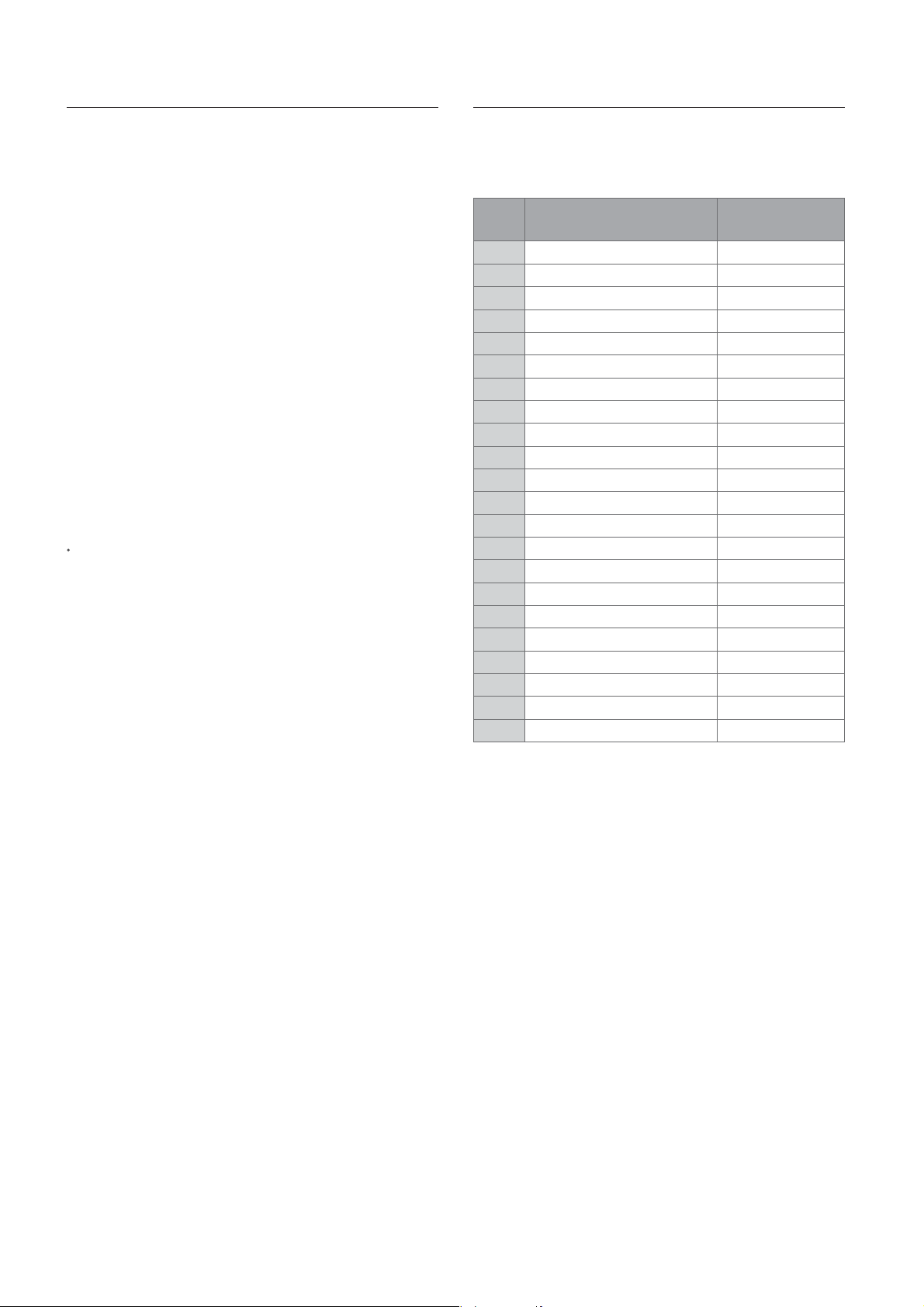
Parts List19.
Case Parts19.1
Item No Part No. Boiler Size Description Item No Part No. Boiler Size Description
1 ECP20001 ALL Case 10 ECP20010 ALL APS (Air Pressure Sensor)
2 ECP20002 ALL Top bracket 11 ECP20011 ALL APS bracket
3 ECP20003 ALL Bottom bracket 12 ECP20012 ALL Tube
4 ECP20004 ALL Lock out 13 ECP20013 ALL Cover
5 ECP20005 ALL Insulation top 14 ECP20014 ALL Controller Ass’y
6 ECP20006 ALL Insulation side 15 ECP20015 ALL Air Intake Packing
7 ECP20007 ALL Controller bracket (L) 16 ECP20016 ALL Air Intake Plate
8 ECP20008 ALL Controller bottom bracket 17 ECP20017 ALL Case Clip
9 ECP20009 ALL Controller Bracket (R)
EHC
43Parts List
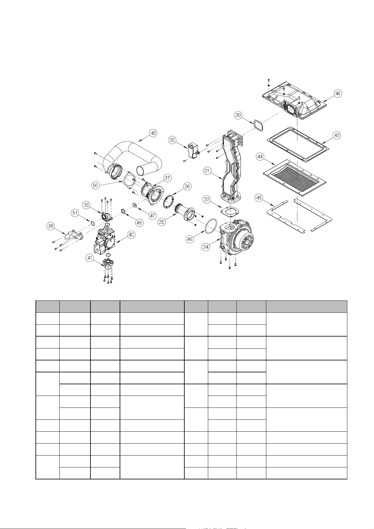
Burner Parts19.2
Item No Part No. Boiler Size Description Item No Part No. Boiler Size Description
30 ECP20030 ALL Mix chamber packing ECP30043 21/25kW
31 ECP20031 ALL Mixing flow guide ECP40043 32/37kW
32 ECP20032 ALL Ignition trans ECP30044 21/25kW
33 ECP20033 ALL Fan packing ECP40044 32/37kW
34 ECP20034 ALL Fan assay ECP30045 21/25kW
ECP50035* 21/25kW Mixer Chamber Assembly ECP40045 32/37kW
35
36
37
ECP60035* 32/37kW Mixer Chamber Assembly ECP30046 21/25kW
* Note: Items 35, 36 & 37 must be ordered as an assembly
ECP30038 21/25kW ECP40046 32/37kW
38 Gas pipe assay
ECP40038 32/37kW ECP30047 21/25kW
39 ECP20039 ALL Gas outlet adapter ECP40047 32/37kW
40 ECP20040 ALL Gas control valve 48 ECP20048 ALL Gas nozzel packing
41 ECP20041 ALL Gas inlet adapter 49 ECP20049 ALL O-ring (Mixer box sealing)
ECP30042 21/25kW 50 ECP20050 ALL Air supply pipe packing
42 Air supply pipe
ECP40042 32/37kW 51 ECP20051 ALL Gas Valve O-Ring
43
44
Burner packing
Burner Assay
Heat exchanger packing (gasket)45
Mix Chamber46
Gas Nozzle47
44
Parts List
EHC

Water Way Parts19.3
82
120
EHC
45Parts List

Item No Part No. Boiler Size Description Item No Part No. Boiler Size Description
80 ECP20080 All Burner fixing rack 101 ECP20101 All Heating supply pipe 1
ECP70081 21kW 102 ECP20102 All Heating supply pipe assay
*
ECP71081 25kW ECP30103 21/25kW
81
82
120
83 ECP20083 All Exhaust duct adaptor packing ECP30105 21/25kW
84 ECP20084 All Exhaust duct ECP40105 32/37kW
85 ECP20085 All Secondary heat exchanger bracket R 106 ECP20106 All DHW outlet pipe
86 ECP20086 All Secondary heat exchanger bracket L 107 ECP20107 All DHW outlet adaptor
87 ECP20087 All Siphon hose 108 ECP20108 All Cap
88 ECP20088 All Siphon hose clip 109 ECP20109 All DHW inlet pipe 1
89 ECP20089 All Siphon 110 ECP20110 All DHW inlet pipe 2
90 ECP20090 All Secondary heat exchanger oulet adaptor 111 ECP20111 All 3 way valve
91 ECP20091 All Secondary heat exchanger inlet adaptor 112 ECP20112 All Heating supply adaptor
92 ECP20092 All
93
94 ECP20094 All Primary heat exchanger inlet adaptor ECP30116 21/25kW
95
96 ECP20096 All Circulation pump 118 ECP20118 All Expansion pressure hose
97 ECP20097 All Strainer 119 ECP20119 All Expansion pressure hose clip
98 ECP20098 All Heat return pipe A ECP30121 21/25kW
99 ECP20099 All Heating return adaptor ECP40121 32/37kW
100 ECP20100 All Pressure relief valve
* Note: Items 81, 82 & 120 must be ordered as an assembly
*
ECP72081 32kW ECP40103 32/37kW
*
ECP73081 37kW 104 ECP20104 All Fl ow sensor
*
ECP30093 21/25kW 114 ECP20114 All Check valve
ECP40093 32/37kW 115 ECP20115 All Temperature limit sensor
ECP30095 21/25kW ECP40116 32/37kW
ECP40095 32/37kW 117 ECP20117 All Expansion vessel
Heat Exchanger Assembly
Primary and secondary heat exchanger
connection pipe
Hot water outlet pipe
Primary heat exchanger inlet pipe
103
105
113 ECP20113 All W ater pressure sensor
116
121
DHW exchanger
Water inlet adaptor A, B
Electrode rod
Temperature limit sensor
46
Parts List
EHC
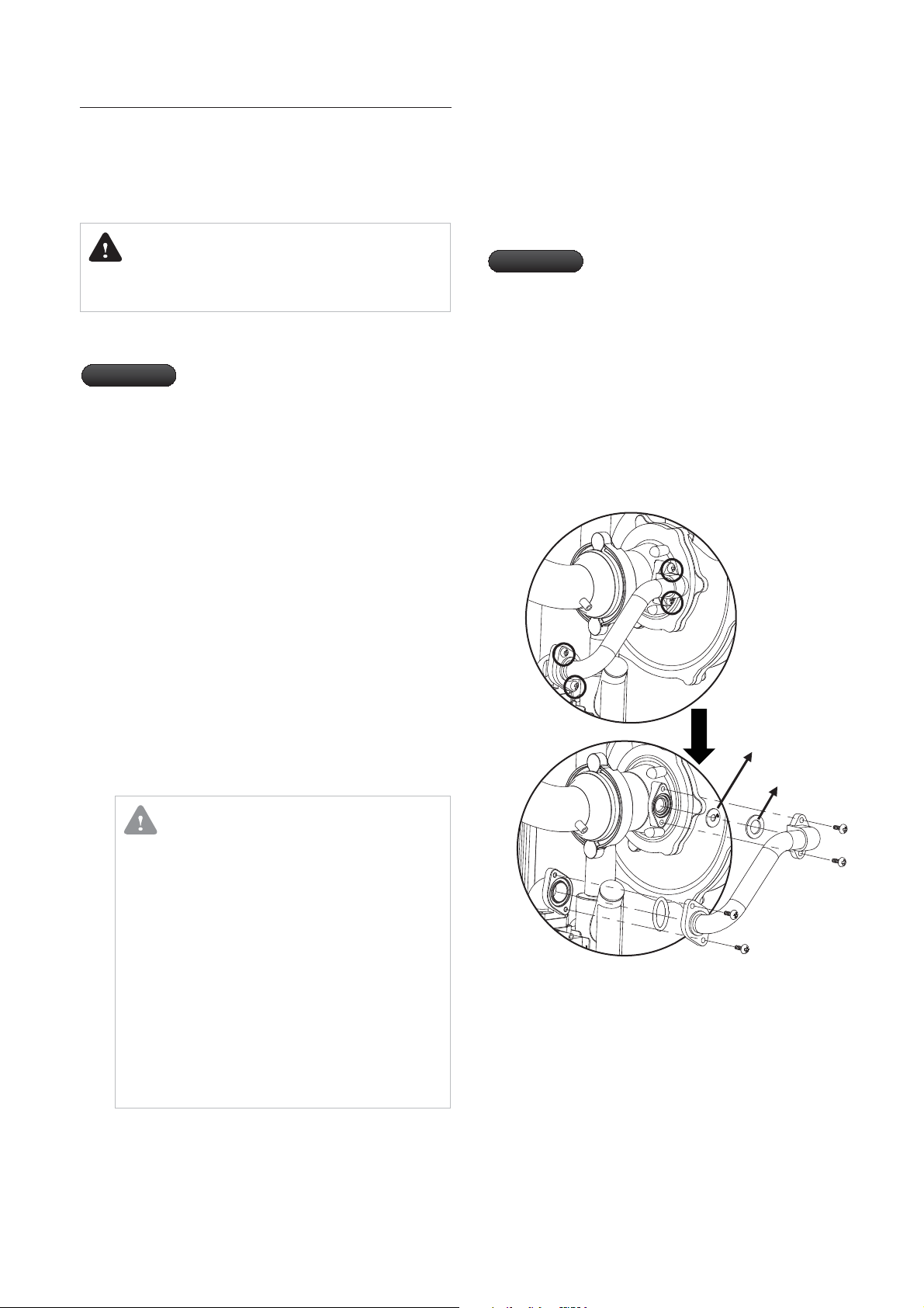
Appendix A
Gas Conversion
If the type of gas needs to be converted from the one specied
on the data plate, the specic “gas conversion kit” must be
requested for a quick and easy conversion.
Replace the front cover.15.
Put a new data plate with the correct type of gas and16.
correct inlet pressure on the old plate.
DANGER
Conversion of the gas type must be performed by a fully
qualified Gas Safe Engineer.
Convert the gas type by installing the gas conversion kit and
adjusting the CO
Important
Turn o the power.1.
Close the gas shutoff valve on the gas supply.2.
Remove the front panel of the appliance.3.
Replace t4. he gas nozzle located on the gas connection pipe
with the fan.(fig 1)
Connect a flue gas analyzer probe at the flue gas connector 5.
to the flue outlet.
Open the gas shutoff valve on the gas line.6.
Make sure that the gas nozzle is not leaking.
7.
8.
R eplace the front cover and turn on the power.
9.
Check the maximum and minimum output CO
After prepare the following gure(g 2) with manometer,10.
the boiler set to condition at minimum rated output.
The boiler is settled under minimum rated output after11.
a round 30 seconds.
12.
After should checked to manometer, if Gas/Air ratio is not
located in 0~ -0.1mbar as the following figure(fig 3), you
s hould adjusted the adjustment screw "C" on the gas valve.
2
level using the following procedures.
With the "Nozzle and Venturi" table, ensure
that you prepare the correct size of nozzle
and venturi before starting the conversion
procedures.
2
levels.
Important
Once you ensure that all of the specied
nozzles and ports are properly connected,
and the CO
following items:
There is no ame return in the t
combustion chamber.
The ame is not excessively high or t
separated from the burner.
All the probes used during the t
conversion are perfectly sealed.
There are no gas leakages.t
2
levels are correct, check the
Nozzle
Packing
CAUTION
Ensuring the CO2 level
Ensure that maximum and minimum output CO
Levels are within the tolerances detailed in the
"CO Level" tabel.
2
If the minimum output CO level is not correct, adjust
it by turning the screw located on the gas valve. Turn
it to the right to increase the CO level, and turn it
to the left to decrease it. After adjusting it, check the
maximum output CO level again.
2
2
2
Adjusting the nozzle pressure value
Adjust the nozzle pressure with the gas-air ratio
adjustment screw “C” so that the oset value falls
between 0 to -0.1 mbar.
After the adjustment, turn o the power.13.
Close off the flue test point after you are satisfied that the 14.
analyzer reading are correct. Ensure that test point "B" and
"C" are fully tightened after the gas/air ratio has been set.
EHC
2
Fig 1. Disassembly
of Nozzle
47Appendix

Nozzle and Venturi
Gas Type Item
G20
G31
Ø nozzle 5.8 5.8 6.8 6.8
Ø Venturi20202424
Ø nozzle 4.4 4.4 5.3 5.3
Ø Venturi20202424
Ecosave
21K(A)
Gas Nozzle Pressure and Flow Rate
Model
Ecosave
21K(A)
Ecosave
25K(A)
Ecosave
32K(A)
Ecosave
37K(A)
Gas Category
Output Input
Load kcal/h kW kW m3/h m3/h
Max. 16,598 19.3 19.6 2.098 0.791
Min. 4,128 4.8 4.9 0.542 0.196
Max. 19,866 23.1 23.5 2.513 0.955
Min. 4,128 4.8 4.9 0.542 0.196
Max. 25,370 29.5 30.0 3.214 1.207
Min. 5,848 6.8 7.0 0.750 0.281
Max. 29,412 34.2 34.9 3.720 1.398
Min. 5,848 6.8 7.0 0.750 0.281
[ 20 mbar ]
G20
Gas Flow
Rate
Ecosave
25K(A)
G31
[ 37 mbar ]
Gas Flow
Rate
Ecosave
32K(A)
Ecosave
37K(A)
CO2 Level
Gas Type Mode
G20
G31
Output
Max.
Min.
Max.
Min.
Gas
test point “B”
Ecosave
21K(A)
CH Mode 9.4 9.4
DHW Mode
CH Mode
DHW Mode
9.4 9.4
9.1 9.1
10.4
10.4
10.0
Digital
pressure
manometer
Ecosave
25K(A)
10.4
10.4
10.0
Ecosave
32K(A)
9.5
9.5
9.2
10.2
10.2
10.0
Adjustment screw “C”
Gas test point “B”
Gas test point “A”
Ecosave
37K(A)
9.5
9.5
9.2
10.2
10.2
10.0
48
Appendix
Fig 2. Connection of
Manometer
Fig 3. Test point of
Gas valve
EHC

Appendix B
B.1
Warranty
Standard Terms & Warranty Conditions
2 Years Warranty - register today
To receive your 2 years parts + labour warranty, please complete
WarrantyRegistraiton Card supplied with the appliance or simply
call EHC Ltd on Tel No:01698 820533
Our Promise
If you experience any malfunctions with your new appliance, we
aim to provide safe and high quality repair services supported
by our dedicated national network of highly skilled engineers. If
your installer cannot solve the problem for you, we will arrange
for an engineer to service your appliance as soon as possible.
rights.
What this Warranty Covers
Free repairs or the replacement of components found to be
faulty from manufacture.
If the appliance fails due to manufacturing related issues,
the entire appliance will be replaced free of charge if it is
determined that the appliance cannot be repaired, or it is not
economically feasible to repair it.
installation.
What this Warranty Does NOT Cover
Repairs of the appliance which have not been detailed in the
B.2
Registration is simple. Just complete the Warrnaty Registration
Card and return to EHC Ltd within 30 days of installation. Your
details will be automatically registered within the EHC Warranty
Registration Scheme.
B.3
If the appliance malfunctions when it is initially operated,
contact your installers. Their professional assessment is needed
under the terms of our Warranty.
If you are unable to contact your installer, call the EHC Technical
Department on Tel No: 01698 820533
B.4
The appliance is a state-of-the-art appliance which has been
constructed in accordance with recognized safety regulations.
Nevertheless, if the appliance is misused or used for applications
for which it is not intended for, the user or others may incur
the risk of injury or death, or incur damage to the appliance or
property.
The appliances are designed to generate heat for domestic
hot water and to be connected to hot water central heating
systems. Any other usage shall be considered to be usage
other than what was originally intended. The manufacturer/
supplier is not liable for any resulting damage. The user alone
bears the risk. Intended usage includes the observance of the
instructions for use and installation instructions and all other
applicable documents, as well as adherence to maintenance
and inspection conditions.
Warranty Registration
Immediate Help
Intended Use
Any damage caused by hard water scale deposits and/or
aggressive water resulting from corrosion.
Any other defects or failures, either in the connected heating
system or outside of the appliance itself.
Faults caused by inadequate supplies of electricity, gas or
water to the property.
Installations not suited to the original design of the boiler.
Reimbursement of any third party repair or replacement
costs that were not approved by EHC Ltd Prior to the repair
taking place.
Compensation for consequential losses (e.g., loss of earnings,
business losses, stress and inconveniences) arising from a
production breakdown, including repair delays caused by
factors beyond our reasonable control.
B.5
Clean the exterior of your appliance with a damp cloth.
DO NOT use any abrasive products to clean the appliance.
B.6
Please observe the applicable national legal regulations.
Care
Recycling and Disposal
The Appliance
Do not dispose of the appliance or any of its accessories with
household waste. Make sure that the old appliance and any
existing accessories are disposed of properly.
Packaging
Leave the disposal of the transport packaging to the installer
that installed the appliance.
EHC
49Appendix

Appendix C
GAS BOILER SYSTEM COMMISSIONING CHECKLIST
This Commissioning Checklist is to be completed in full by the competent person who commissioned the boiler as a means of demonstrating
compliance with the appropriate Building Regulations and then handed to the customer to keep for future reference.
Failure to install and commission this equipment to the manufacturer’s instructions may invalidate the warranty but does not affect statutory rights.
Customer Name Telephone Number
Address
Boiler Make and Model
Boiler Serial Number
Commissioned by (print name) Gas Safe Register Number
Company Name Telephone Number
Company Address
Commissioning Date
To be completed by the customer on receipt of a Building Regulations Compliance Certificate
Building Regulations Notification Number (if applicable)
:
*
CONTROLS Tick the appropriate boxes
Time and Temperature Control to Heating Room Thermostat and Programmable
Programmer/Timer
Time and Temperature Control to Hot Water Cylinder Thermostat and Programmer/Timer Combination Boiler
Heating Zone Valves Fitted Not Required
Hot Water Zone Valves Fitted Not Required
Thermostatic Radiator Valves Fitted Not Required
Automatic Bypass to System Fitted Not Required
Boiler Interlock Provided
Room Thermostat Compensation Control
Load/Weather Optimum Start
ALL SYSTEMS
The system has been flushed and cleaned in accordance with BS7593 and boiler manufacturer’s instructions Yes
What system cleaner was used?
What inhibitor was used? Quantity
CENTRAL HEATING MODE Measure and Record:
Gas Rate
Burner Operating Pressure (if applicable)
Central Heating Flow Temperature
Central Heating Return Temperature
m3/hr OR
mbar OR Gas Inlet Pressure mbar
COMBINATION BOILERS ONLY
Is the installation in a hard water area (above 200ppm)? Yes
If yes, has a water scale reducer been fitted? Yes
What type of scale reducer has been fitted?
DOMESTIC HOT WATER MODE Measure and Record:
Gas Rate
Burner Operating Pressure (at maximum rate)
Cold Water Inlet Temperature
Hot water has been checked at all outlets Yes
Water Flow Rate
m3/hr OR
mbar OR Gas Inlet Pressure (at maximum rate) mbar
No
No
Temperature
CONDENSING BOILERS ONLY
The condensate drain has been installed in accordance with the manufacturer’s instructions and/or BS5546/BS6798 Yes
litres
ft
°C
°C
ft
°C
°C
l/min
3
/hr
3
/hr
ALL INSTALLATIONS
If required by the manufacturer, record the following CO
The heating and hot water system complies with the appropriate Building Regulations Yes
The boiler and associated products have been installed and commissioned in accordance with the manufacturer’s instructions Yes
The operation of the boiler and system controls have been demonstrated to and understood by the customer Yes
The manufacturer’s literature, including Benchmark Checklist and Service Record, has been explained and left with the customer Yes
Commissioning Engineer’s Signature
Customer’s Signature
(To confirm satisfactory demonstration and receipt of manufacturer’s literature)
All installations in England and Wales must be notified to Local Authority Building Control (LABC) either directly or through a Competent Persons Scheme.
*
A Building Regulations Compliance Certificate will then be issued to the customer.
©Heating and Hotwater Industry Council (HHIC) www.centralheating.co.uk
% OR CO ppm OR CO/CO
2
Ratio
2

SERVICE RECORD
It is recommended that your heating system is serviced regularly and that the appropriate Service Record is completed.
Service Provider
Before completing the appropriate Service Record below, please ensure you have carried out the service as described in the manufacturer’s
instructions.
Always use the manufacturer’s specified spare part when replacing controls.
SERVICE 1 Date
Energy Efficiency Checklist completed?
Engineer Name
Company Name
Telephone Number
Gas Safe Register Number
Comments
Signature
SERVICE 3
Date
Energy Efficiency Checklist completed? Yes
Engineer Name
Company Name
Telephone Number
Gas Safe Register Number
Comments
Signature
Yes
SERVICE 5 Date
Energy Efficiency Checklist completed?
Engineer Name
Company Name
Telephone Number
Gas Safe Register Number
Comments
Signature
Yes
No
No
No
SERVICE 2 Date
Energy Efficiency Checklist completed?
Engineer Name
Company Name
Telephone Number
Gas Safe Register Number
Comments
Signature
SERVICE 4
Date
Energy Efficiency Checklist completed? Yes
Engineer Name
Company Name
Telephone Number
Gas Safe Register Number
Comments
Signature
Yes
SERVICE 6 Date
Energy Efficiency Checklist completed?
Engineer Name
Company Name
Telephone Number
Gas Safe Register Number
Comments
Signature
Yes
No
No
No
SERVICE 7
Date
Energy Efficiency Checklist completed?
Engineer Name
Company Name
Telephone Number
Gas Safe Register Number
Comments
Signature
SERVICE 9 Date
Energy Efficiency Checklist completed?
Engineer Name
Company Name
Telephone Number
Gas Safe Register Number
Comments
Signature
Yes No
Yes
No
SERVICE 8
Date
Energy Efficiency Checklist completed?
Engineer Name
Company Name
Telephone Number
Gas Safe Register Number
Comments
Signature
SERVICE 10 Date
Energy Efficiency Checklist completed?
Engineer Name
Company Name
Telephone Number
Gas Safe Register Number`
Comments
Signature
Yes No
Yes
No


Disclaimer: All details within this document are correct at the time of printing however they may be subject to change.

EHC Ltd.
ISO 9001:2008
 Loading...