

EHC eco SAVE 750, eco SAVE 1000, eco SAVE 1250, eco SAVE 1500, 750 Operating And Installation Instructions
...
1
(11/15)
E1400236
the electric heating company
Electric Radiator
Operating and Installation Instructions
Models:
eco SAVE: 750 - 1000 - 1250 - 1500
NOTE:
A qualied electrician must carry out the electrical installation of this radiator. The Electrical
installation must comply with the current UK regulations to BS.7671. Any claim on the warranty
could be invalid if these requirements have not been met.

2
GENERAL INFORMATION
The EHC eco SAVE heater has a special aluminium cast body designed to maximize the rate of
convected and radiated heat through the circulation channels providing an efcient comfortable
heating experience. The heaters are lled with a high performance heating oil in a unique way that
provides a bubble free process to ensure that the heaters entire surface area is covered.
The eco SAVE heater has an inbuilt programmer that allows you to set the heater times and
temperatures locally or when connected with the eco SAVE Smart Gateway allows you to set your
heaters remotely via the internet.
Designed and fabricated in accordance with EN 60335-1, EN 60335-2 and EN 55014 (regulations
for domestic appliances).
Standard colour White (RAL 9016).
Class I.
Wall mounted (by quick xing system).
Capillary over temperature safety limiter.
Overheat protection.
On-off main switch.
Key-pad locking (anti-tamper).
NTC electronic sensor.
Fitted with mains power cable 1300mm long.
Important Information - Safety notes regarding the appliance.
Due to the surface of the heater becoming hot, it must not be positioned directly against or below
ammable surfaces.
Do not dry clothes or towels on the heater nor leave fabrics, magazines, spray cans, volatile
substances or similar objects within 250mm of the heater.
In case of breakdown or damage turn off the appliance at the main On / Off switch and notify the
supplier.
If the electricity cable gets damaged it must only be replaced by a technician appointed by the
supplier. This will avoid possible risks and ensure that special tools are available if needed.
This appliance is not intended to be used by persons (incl. children) with limited physical, sensory
or mental capabilities, or who lack experience, except for those under supervision or have received
instruction in the use of the appliance from a person responsible for their security.
Children must be supervised in order to ensure that they do not play with the appliance.
WARNING: In order to prevent overheating, do not cover this appliance. There has to be free
movement of air around all surfaces of the appliance.
Main components
Heating Elements. A high quality mono-tube heating element is used with all eco SAVE Heaters. It is
connected to the radiators electronic control system that allows the heater to either be set manually or
remotely via the Internet when using the eco SAVE Smart Home system.
The radiator also has an ON - OFF power switch on the side of the heater for easy isolation.
This symbol “DO NOT COVER”, is placed on the heater as a reminder to
the user.
3
Location
An ideal location of where to site a radiator would be as close as possible to the coolest wall within
a room. It is not recommended to mount the radiator on an un-insulated exterior wall. If this is the
only wall available, we would recommend insulating behind the radiator in this instance.
When installing a radiator in bathrooms the heater must be sited inside the protected zone. The
radiators must be installed within zone 2 making sure that the control unit & ON/OFF switch on the
heater are not reachable directly or indirectly by a person in a bath / shower or using the wash basin.
(Refer to the zone table Fig.B)
Under no circumstances should the radiator be installed below an electric power point.
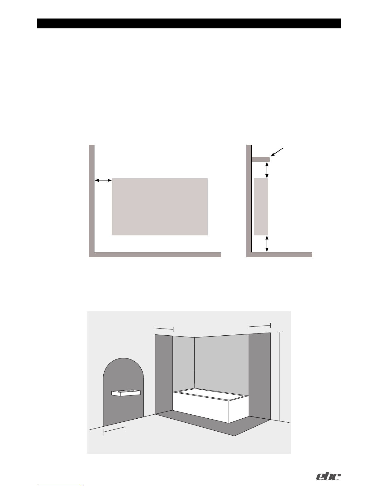
Choose the location of the radiator in respect of the minimum distances that are indicated in Figure A.
window sill
150mm.
150mm. min.
unobstructed space each side
135mm.
Fig. A
Note: If the window sill protrudes less than 20mm the gap above the heater can be disregarded.
Fig. B
Zone
1
Zone
0
Zone
2
Zone
2
600mm
600mm
2250mm
600mm radius
4
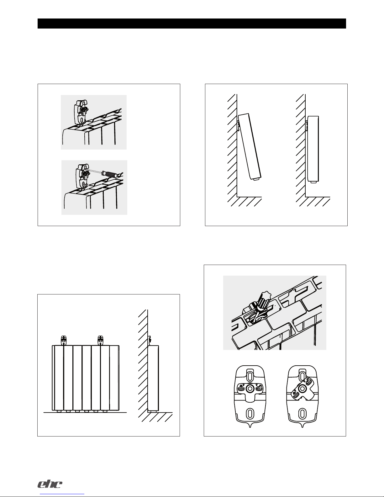
Sit the radiator on the oor and place the
supports between the ns as shown in Figure
2a, Mark the points on the wall through the xing
holes as shown in Figure 2b.
Lift the radiator and hang it on the supports, as
shown in Figure 4a and 4b.
As soon as the radiator is mounted on the
supports, press on the locking plate until a click is
heard. as shown in Figure 5.
Figure 4a Figure 4b
Fix the supports to the wall using the screws and
plugs provided.
Be sure that the supports are level and mounted
in the correct positions as shown in Figure 3.
For radiators with 12 ns (1.5Kw) the supports
should be mounted between Fins 2&3, For all
other radiators the supports should be mounted
between ns 1&2.
Figure 2a
Figure 2b
Mounting The Radiator
Figure 3
unlocked locked
Figure 5
1 3
2
4

5
Technical Data
MODEL
Number Of
Fins
Power
Rating (W)
Size (mm)
Net Weight
(Kg.)
Fuse
Rating
ehc eco SAVE 750 - RA1S1531S2
6 750 580 x 580 x 100 12 5 Amp.
ehc eco SAVE 1000 - RA1S1131S2
8 1000 740 x 580 x 100 16 10 Amp.
ehc eco SAVE 1250 - RA1S1631S2
10 1250 900 x 580 x 100 20 10 Amp.
ehc eco SAVE 1500 - RA1S1331S2
12 1500 1060 x 580 x 100 24 10 Amp.
ehc eco SAVE 1800
12 1800 1060 x 580 x 100 24 10 Amp.
ehc eco SAVE 350
3 350 340 x 580 x 100 6.9 5 Amp.
ehc eco SAVE 500
4 500 420 x 580 x 100 8 5 Amp.
WARNING – THIS APPLIANCE MUST BE EARTHED
The installation of this appliance should be carried out by a competent electrician in
accordance with I.E.E.Regulations BS 7671.
The radiators are supplied with a standard UK 3 pin plug that can be directly
connected to a electrical outlet socket. Care must be taken when multiple radiators
are connected in this way to avoid overloading the ring main circuit of the property.
If you are unsure contact a qualied electrician before connecting multiple radiators.
Alternatively the heaters main power cable can be cut to length and connected to a suitable
20 amp double-pole fused switched spur. The spur must be supplied using a cable with a
minimum size of 2.5mm Sq. Cable sizing must be carried out by a qualied electrician.
Note: Ensure that the heaters are protected using the correct fuse size as listed in the table
below.
Connecting wires:
Brown: Live
Blue: Neutral
Yellow-green: Earth
Electrical Connection

6
The control is based on four buttons and an LCD display.
Switching ON (Master):
Once the radiator has been mounted on the wall
and correctly connected to the mains power supply,
press the main On-Off switch on the right hand side
of the radiator.
After approx 3 seconds the screen will illuminate
and the radiator is ready to operate.
Switching OFF (Master):
To switch the radiator Off press the main On-Off
switch on the right hand side of the radiator. The LCD
screen will go blank. If the radiator is connected to an
EHC eco Save Smart Gateway, the radiator will now
lose connection with the gateway.
Stand-by function “ OFF“:
Press the Mode/OK button until the symbol is
present as shown in the following screen.
When the radiator is in Stand-by Mode it will retain
its program settings. If the radiator is connected
to an eco SAVE Smart Gateway it will continue to
communicate with the gateway.
To switch the radiator ON again, press the MODE
button to choose program mode or manual
mode you will see the following screens:
Programmed hours
Desired
temperature
Days of the week
Radio paired icon
Current Mode
(AUTO,
MANUAL,
OFF)
OPERATING INSTRUCTIONS
Heating indicator
main switch
Increase Decrease Mode/OK CONFIG
AUTO / MANUAL
/OFF
PROG

7
When the temperature setup icon starts
ashing, press OK to scroll through each
temperature mode.
COMFORT ECONOMY FROST
Press the +/- button to select the temperature
of your chosen mode, press CONFIRM to exit the
temperature setting screen.
To start programming press and hold CONFIG/
PROG button for 3 seconds and the following
screen will appear:
The programming starts on (1) Monday at 00:00,
Choose your temperature mode.
COMFORT ECONOMY or FROST by
pressing the OK button, then press +/- buttons to
select your programme times.
(Press the OK button to choose between Comfort,
Economy or Frost Protection modes)
Program hours will show; Two blocks for Comfort,
One block for Economy and No blocks for frost
protection.
When a full day has been programmed, the
screen moves onto the following day (2). When
you reach the 7th day the display will automatically
move to real time clock settings. To select your
day of the week press +/- buttons and conrm with
the OK button.
Next, the hour of the day will be displayed.
Select your hour by pressing the +/- buttons.
Conrm with OK.
Next, the minutes will be displayed. Select your
minutes by pressing the +/- buttons. Conrm with
OK.
Your heater is now fully programmed and clock
set.
Manual Programming
Setting Programs and Real time Clock
To assist with programming the LCD screen
has a backlit display and will stay illuminated for
approximately 10 seconds after the last button is
pressed.
When the radiator is working in the manual
mode and the ambient temperature is below the
set temperature, the heater will be operating. The
heating symbol on the right side of the screen will
be shown .
When the ambient temperature has reached the
set point the heating symbol will disappear.
The screens below show:
OFF, AUTO and MANUAL modes.
To chose different modes press MODE/OK
button.
AUTO Mode:
When the radiator is in the AUTO mode the
temperature can be adjusted by pressing the +/buttons. This change will remain active until the
next program change or until midnight when the
temperature will revert to the preset value.
Adjust Programmed Temperatures
You can adjust your Comfort,Economy & Frost
temperatures in the following way;
Press the CONFIG button and the following
screen will appear :
Note: If your radiators are used in conjunction
with an eco SAVE Smart System, the real time will
automatically be set from the internet, and you will
be able to program your heaters directly from your
computer,tablet or smart phone.

8
Programming with EHC Smart kit
To program your eco SAVE heater with the eco
SAVE Smart Wi Kit, you must pair the radiator to
the gateway. First you must activate the pairingdiscovery mode of the eco SAVE Smart gateway.
Details of this can be found in the Smart gateway
instruction manual.
Once this is done press the CONFIG button on
the radiator and use the + or - key until the RF icon
ashes. Press OK and ‘Link’ together. An antenna
icon will appear in the top right of the screen when
connected.
Another way to pair the radiator is to press the
OK button for 3 seconds while the radiator is in
one of the main modes (OFF, AUTO, MANUAL).
Your Eco SAVE heater is now ready to accept
program instructions from the eco SAVE Smart
Gateway.
If the radiator has been linked to the gateway
and for some reason communication is lost, the
Link icon disappears and the antenna starts
ashing.
Keypad Locking (Anti-Tamper)
The keypad can be locked to prevent any
unauthorised person (children, people in public
places, nurseries, ofces, hotels etc.) altering the
settings of the radiator. To lock the keypad depress
and hold the + and – buttons at the same time for
3 seconds until “bloc” appears on the screen. Any
button presses will be ignored and “bloc” will be
display on the screen.
To unlock keyboard, once again press and
hold + and - for 3 seconds until the word ‘bloc’
disappears.
When the keypad is locked the radiator will
still receive communications from the eco SAVE
Smart Gateway.
Advanced Engineer settings
To enter the advanced settings mode, press
CONFIG while the radiator is in one of the main
modes (OFF, AUTO, MANUAL). The following
window will appear:
Now press the CONFIG button for 5 seconds
and C1 appears on the screen.
To select one of the three advanced settings (C1
to C3) use the +/- keys and choose the required
mode by pressing OK. The advanced settings are:
1. C1-> Choose ºF or ºC
2. C2-> Choose type of control
3. C3-> Temperature Compensation
Degrees Fahrenheit or Celsius (C1)
Select ºC or ºF with the +/- keys and conrm
with OK button.
Type of Control (C2)
You access the setting mode control, showing the
type of control currently used. There are 4 types
of control PID, hysteresis of 0.25ºC, hysteresis
of 0.35ºC, hysteresis of 0.50ºC and hysteresis of
0.75ºC.
To change type of control press +/-. Conrm with
OK.
The screens shown are:
Temperature Compensation (C3)
When in this mode the display will show offset
adjustments. The measured temperature is
displayed once taken into account the offset. With
the +/- keys offset can be changed and conrmed
with OK. Temperature compensation can be
adjusted up to +/- 3°C.

9
Radiator Factory Reset
The device RESET returns all settings to their
default values. It will also delete its RF network
(delete pairing) if paired with an eco SAVE Smart
Home gateway.
To activate the RESET feature press the OK
button and the CONFIG button together for 10
seconds.
The following screen will appear:
To conrm the reset, press OK again, to cancel
the RESET press any other key.
Default Values
• Working mode: OFF
• Comfort Temp : 19ºC
• Economy Temp : 17ºC
• Frost Protection Temp : 5ºC
• Manual mode Temp: 19ºC
• Temperature Compensation: 0ºC
• No RF paired network
• Temperature units ºC
• Control type: PID
• Default Programme: All Economy

10
The eco SAVE heaters are lled with a precise amount of high performance heating uid that requires no
further maintenance. In the event of a warranty repair being carried out during the heaters warranty period,
EHC should be notied of the fault. The heater should be returned to EHC for the repair to be carried out
or if agreed, an accredited engineer will visit site to repair the heater. If it is found that the heater has failed
due to incorrect installation or misuse then the engineers call-out will be chargeable including any parts used.
Regulations regarding the disposal of heating uids should be adhered to protect the environment.
The surfaces of the radiator must not be cleaned with an abrasive product or those containing granular
substances. We recommend regular cleaning with PH neutral products when cleaning the radiator, It is
recommended that the electric power is switched off.
USEFUL TIPS; Sometimes stains can be seen above radiators, on the wall or ceiling. This is caused by
dust particles in the air and it is not attributable to the heater. Frequent cleaning of the heater and surrounding
areas will help prevent this from happening.
MAINTENANCE AND CARE

11
Installation Notes:

12
(Waste Electrical & Electronic Equipment)
(Applicable in the European Union and other European countries with separate
collection systems)
This marking shown on the product or its literature, indicates that it should not be disposed of
with other household wastes at the end of its working life.
To prevent possible harm to the environment or human health from uncontrolled waste
disposal, please separate this from other types of wastes and recycle it responsibly to promote
the sustainable reuse of material resources. Household users should contact either the retailer
where they purchased this product, or their local government ofce, for details of where and
how they can take this item for environmentally safe recycling.
Business users should contact their supplier and check the terms and conditions of the
purchase contract. This product should not be mixed with other commercial wastes for disposal.
ns of the purchase contract. This product should not be mixed with other commercial wastes
for disposal.
Guarantee
Your appliance body is guaranteed for 10 years and 2 years on electric and electronic components from
the date of purchase – during this period we will repair or exchange, at our discretion, any faulty or defective
parts providing the appliance has been used in accordance with the operating & installation instructions and
has not been misused or mistreated in any way.
Any unauthorised repair or attempted repair will invalidate the guarantee. You may be asked to return the
product to EHC for inspection to establish whether the fault is covered under the guarantee.
The guarantee is valid in the UK only.
This guarantee is additional to your statutory rights.
In the unlikely event of a problem with your appliance please contact your supplier.
the electric heating company
Installed by:
Block 5, Unit 40, Third Road
Blantyre Industrial Estate
Blantyre · G72 0UP · United Kingdom
TEL. 01698 820533
info@electric-heatingcompany.co.uk
www.electric-heatingcompany.co.uk
 Loading...