

EHC DSR solaris Series, DSR solaris PSO500.380.58, DSR solaris PSO1000.510.58, DSR solaris PSO2000.770.58, DSR solaris PSO1500.640.58 Installation & Operating Instructions Manual
RCL-CXXW_EHC_R ev.0_05-12-2018
1/26
500w-1000w-1500w-2000w
DSR solaris Electric Heater
INSTALLATION
&
OPERATING INSTRUCTIONS
THESE INSTRUCTIONS SHOULD BE READ CAREFULLY
AND RETAINED FOR FUTURE REFERENCE.
BE SURE TO OBSERVE ALL
LABELS AND WARNINGS
ON THE APPLIANCE

RCL-CXXW_EHC_R ev.0_05-12-2018
2/26
This appliance is not intended for use by persons (including children)
with reduced physical, sensory or mental capabilities, or lack of
experience and knowledge, unless they have been given supervision or
instruction concerning use of the appliance by a person responsible for
their safety. Young children should be supervised to ensure that they do
not play with the appliance.
1. General Information
EHC Electric heaters have been designed using the latest technology to
create an elegant solution for all hard to heat situations. They can be installed
in almost any location, apart from the safety restrictions noted within this
manual. This range has been developed to provide a flexible solution for
electric heating in Domestic properties, Conservatories, Holiday homes,
Offices and in any temporary heating situation. The heaters can be simply
plugged into a standard socket or hard wired into a fused spur.
Wi-Fi Control
DSR Wi-Fi Control is our easy to use App based control system. To take
benefit of this feature you simply need to purchase and connect the heaters to
our DSR Gateway. The DSR Wi-Fi App gives you total control of all your
heaters independently or in groups if required. The system can be controlled
from a Computer, Smart phone or Tablet using our Free App. Additionally by
adding an optional Power Meter to the system will give you further
controllability over the total available power within your home. The Power
Meter constantly monitors the whole house electrical demand. If the set
demand is reached, the system will temporarily disable your chosen heaters
until the demand is reduced, the heaters will then be reactivated automatically.
All EHC heaters are manufactured to the highest safety and quality Standards.
Each heater is CE Marked and carries all the necessary European Approvals.
Each heater is fully checked and tested prior to leaving the factory. We hope
you enjoy the comfort provided by this superior product and we look forward to
being of assistance to you in the future.

RCL-CXXW_EHC_R ev.0_05-12-2018
3/26
GENERAL SAFETY INSTRUCTIONS
1. Please read these instructions fully before starting the device for the first
time. Do not discard the instructions, guarantee, your invoice and, if
possible, the complete packing.
2. The guarantee will be invalidated if the product is not installed or handled
in- line with the recommendations of this manual.
3. Before connecting the appliance, make sure the mains voltage is
sufficient and in correspondence to the marked labels of the appliance.
4. Check the power is sufficient to supply the appliances. Note; the total draw
of the heaters current must not exceed the capacity of the circuit breaker
that protects them.
5. This heater cannot be used in rooms with presence of gases or other
flammable products (glues, etc...)
WARNING: To prevent overheating, Do Not cover or use the heater to dry
6.
clothes.
7. Make sure the power cable or other objects do not come into contact with
the heater surface while in operation.
8. If the power cable becomes damaged it must be replaced by the
manufacturer or a suitably qualified trades person. Failure to comply may
compromise your safety and void your warranty.
9. Check the device and the supply cord regularly. Do not turn the device on
if it is damaged.
10. PRECAUTION: Some parts of this product can reach high
temperatures and could cause burns. Pay special attention when
children or vulnerable people are near this heater.
11. Do not place the device directly under a power socket.
12. Children under the age of 3 should not be allowed to touch or play with the
heater and should be supervised at all times.
13. This device can be switched on/off by children over 8 years of age, as well
as by people with reduced physical, sensory or mental capabilities, only
when suitably supervised adult is present and only when they have been
provided instructions to use of the device. Cleaning must only be carried
out by an appropriate adult

RCL-CXXW_EHC_R ev.0_05-12-2018
4/26
GENERAL SAFETY INSTRUCTIONS
Warning: Do not use this heater near baths, showers or swimming pools.
14.
It should not be possible to access the device's controls from the bath,
shower or any other surface that is in contact with water. (Its use in zones
0 or 1 in bathrooms is totally prohibited: seek advice from a qualified
electrician).
15. For greater safety, this appliance is provided with a device that interrupts
its operation in the case of overheating.
16. This heater has been designed exclusively to be fixed to the wall. For
further information on the fixing systems, consult the section
"INSTALLATION AND WALL MOUNTING" of this manual.
Do not use accessories that have not been recommended by the
17.
manufacturer, as they could entail a potential risk to the user, and damage
the device. Use only original accessories.
18. Keep all the packaging elements (plastic bags, cardboard and
polyethylene) out of the reach of children, as they can cause potentially
dangerous situations.
19. Use this device only for domestic / light commercial use and the tasks for
which it has been designed. This device has not been designed for
industrial use. It must not be used outdoors, in greenhouses or for
animal husbandry. Keep it away from heat, direct sunlight, humidity and
cutting tools. Do not under any circumstances immerse in water or use this
device with wet hands. In the case of humidity or water in the device,
immediately disconnect the power supply and do not touch the wet parts.
20. Do not attempt to service the device yourself. Contact a qualified
technician.
21. To disconnect the heater from a mains socket, pull the plug, never the
supply cord.
22. Respect the "SPECIFIC SAFETY INSTRUCTIONS FOR THIS
APPLIANCE"
RCL-CXXW_EHC_R ev.0_05-12-2018
5/26
SPECIFIC SAFETY INSTRUCTIONS FOR THIS DEVICE
• The appliance must remain in a vertical position.
• Make sure the appliance is secured at all times. Please adhere to the
installation distances indicated in this guide.
• Do not hang any objects in front, behind or on top of the device.
• Always ensure that the inlet and outlet air flow are not obstructed.
• Always install the device so that it cannot enter into contact with any
combustible material, such as curtains or towels.
• To clean the device, consult the instructions in the "MAINTENANCE"
section. If water enters the heater it could seriously damage the device.
• Do not insert any object through the grille or inside the device.
• This heater is designed to be connected by plug to the electric installation
and fixed to the wall installation. Follow the instructions in
"INSTALLATION".
Your Guarantee may be invalidated if the installation
instructions have not been followed
INSTALLATION
• Heaters can be heavy. Take adequate precautions when lifting and
maneuvering the heater. Always assess the load, and seek assistance
with heavy or awkward loads that are beyond your capabilities.
•
In order to maintain stability and to ensure its future safety in use, it is
essential that the heater is FIXED SOUNDLY TO A WALL and that the
brackets are mounted on a FIRM, LEVEL SURFACE.
• Care should be taken to avoid irregular surfaces.
• It is important that these instructions are strictly followed.
• Keep the following minimum safety distances to avoid fire risk due to high
surface temperatures of the appliance during heating cycles.

RCL-CXXW_EHC_R ev.0_05-12-2018
6/26
• CAUTION – This heater must not be located below or in front of a fixed
socket outlet.
• DO NOT POSITION under windows where curtains may contact the
heater.
• DO NOT PLACE THE APPLIANCE in the vicinity of a swimming pool.
• During the first use and for a few minutes, this device may occur smells
and noise due to the dilatation of some internal parts. This is normal, so
you must provide adequate ventilation. The smells are momentary and will
quickly dissipate.
• For greater efficiency, make sure to calculate the correct size of the heater
according to the surface of the room. We recommend contacting your
dealer or engineer to perform this calculation.
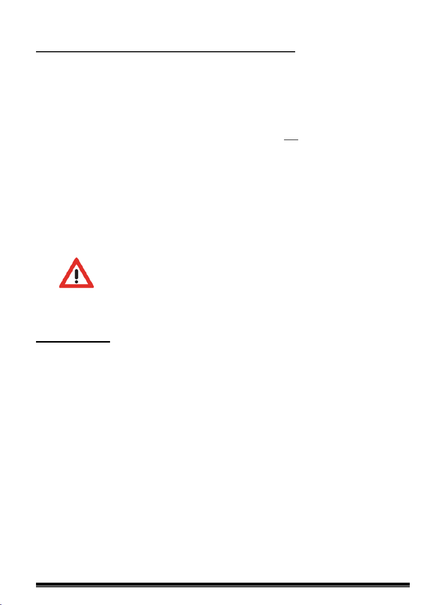
• The heater must be placed at a minimum distance of 15cm from any
combustible material, curtains, furniture, chairs, etc. (Fig.1).
• Allow for a minimum distance of 1m, from the front of the unit to any
obstacles (furniture, walls, curtains, for example) that could hinder its
operation or performance of the product.
• Keep a minimum distance of 15cm between the appliance and the side
walls and any other obstacles (walls, for example) that may affect its
function. Also keep a minimum distance of 35cm on top the appliance free
of obstacles and a minimum distance of 15cm from the floor.
RCL-CXXW_EHC_R ev.0_05-12-2018
7/26
Possible Shel f
Fig1
Minimum Clearances
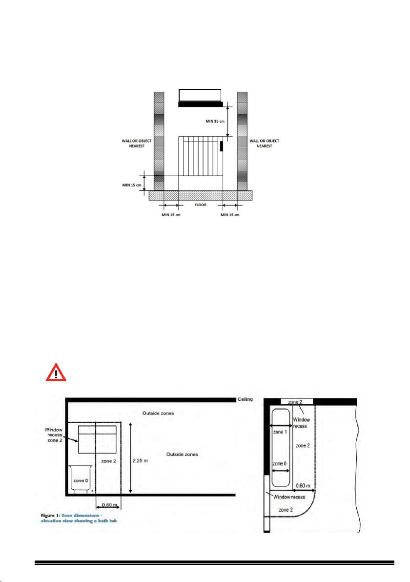
Note: Only IPX4 heaters are suitable for installation in bathrooms which allows
for the heater to be installed within Zone 2 as per regulation 701.32.4
Regulation 701.411.3.3 of BS7671 means that all circuits within a location
containing a bath or shower will require RCD protection not exceeding 30 mA
and have the characteristics specified in regulation 415.1.
Local isolation should be provided for the heater, however, the isolation device
must be installed out with all zones and in compliance with regulation
701.512.3 and Section 53 of BS7671
Note: Heaters must be only installed in or out with zone 2 of a bathroom
RCL-CXXW_EHC_R ev.0_05-12-2018
8/26
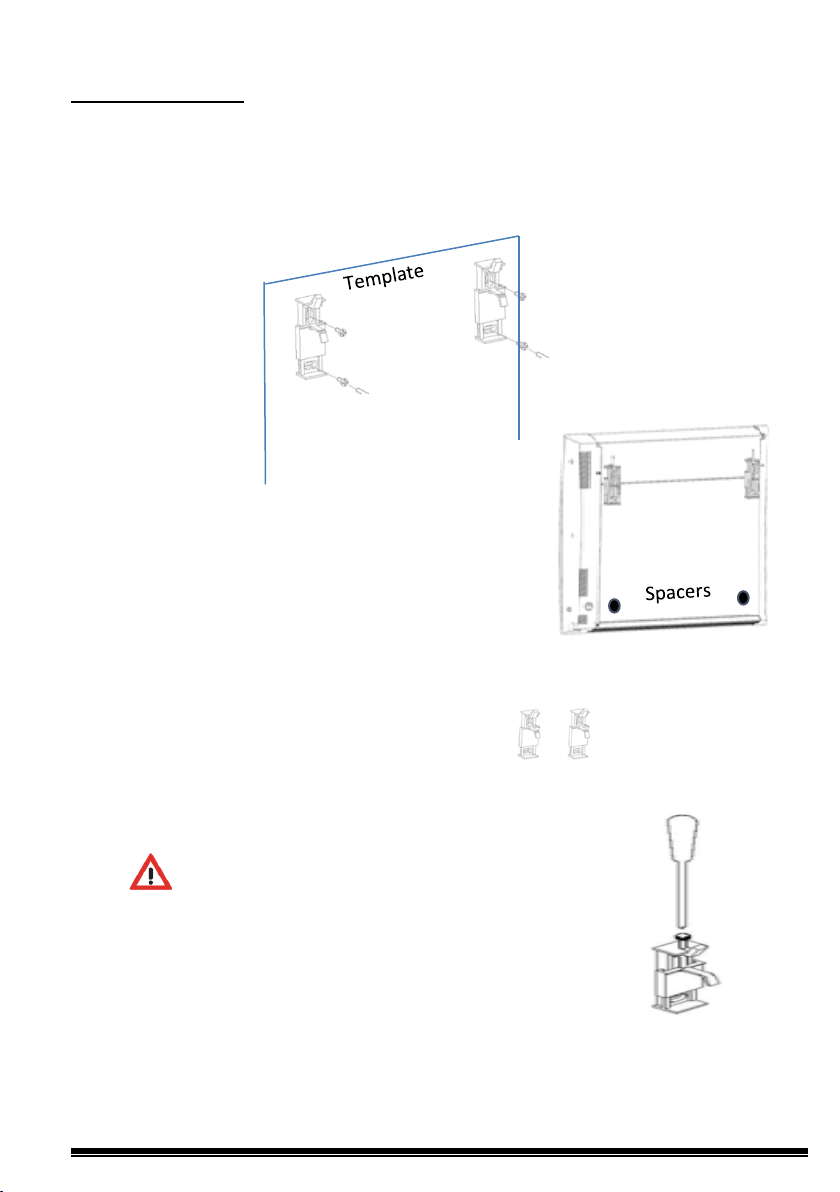
WALL-MOUNTING
1. Place the template onto the floor and mark the drilling positions for
the heater brackets. Use the Screws & Plugs provided to fix the
brackets to the wall.
2. Attach the 2 adhesive spacers onto the
heater the back of the heater.
3. Hang the heater onto the brackets and lock into
position by the screwing the locking device into position.
Note: Take care not to over tighten as this may damage
the brackets.

RCL-CXXW_EHC_R ev.0_05-12-2018
9/26
ELECTRIC CONNECTION
The appliance has been designed to be connected to 230V (nominal)
alternating current (AC); 50Hz power supply.
This appliance is equipped with a 1.5 m supply cord fitted with standard UK
sealed 3 pin plug that can be directly connected to a suitable electrical sockets
within the home.
Care must be taken when connecting heaters in this way not to overload the
ring main circuit within the property. If you are unsure contact a qualified
electrician for advice.
Alternatively the supply cord can be cut to length by a Qualified Electrician and
connected to a suitable 13A DP Switched Fuse Spur installed adjacent to the
heater. This connection unit should comply with BS 1364-4 and have a
minimum contact separation of at least 3mm. It is recommended when
connecting to a screwed terminal that the flex ends are crimped to prevent the
copper strands from splaying within the terminal.
All electrical installation work, in particular protective measures, must be
carried out in compliance with BS7671 regulations, statutory provisions and
‘best industry practice’ of the respective utilities provider.
The electrical installation may only be carried out in compliance with the
installation instructions by a suitably qualified electrician.
Electrical Connections
The wires within the supply cord are coloured in accordance with the following
code:
BLUE: NEUTRAL
BROWN: LIVE
GREEN/YELLOW EARTH
WARNING THIS APPLIANCE MUST BE EARTHED

RCL-CXXW_EHC_R ev.0_05-12-2018
10/26
Rated
Voltage
Rated
Frequency
Rated
Power Input
Electrical
Class
IP
Degree
Dimensions
(mm)
Weight (kg)
5.6
8.7
11.5
14.8
TECHNICAL CHARACTERISTICS
Type
PSO500.380.58 PSO1000.510.58
230 V~ 230 V~ 230 V~ 230 V~
50 Hz 50 Hz 50 Hz 50 Hz
PSO1500.640.58 PSO2000.770.58
Protection
Protection
(LxHxD)
380 x 580 x105
500 W 1000 W 1500 W 2000 W
II II II II
IPX4 IPX4 IPX4 IPX4
510 x 580 x 105
640 x 580 x 105
770 x 580 x 105

RCL-CXXW_EHC_R ev.0_05-12-2018
11/26
CONTROLLER INSTRUCTRIONS
1.0 Modes
The heater can work in 3 different modes by pressing the "Mode" button
• Auto Mode
The set temperature varies automatically following the Programmed Schedule,
based on the 3 custom temperatures selected. Each LCD Block indicates
what temperature is active at that time.
• Manual Mode
The "Set Temperature" only changes if the user modifies it by pressing the
and - buttons.
• OFF.
The heater will not heat, but can receive remote instructions if linked to a gateway
that is connected to the internet.
+

RCL-CXXW_EHC_R ev.0_05-12-2018
12/26
Note: When in "Auto Mode" manually adjusting the
temperature
will activate the heater for 1.5 hours, after this time
period has lapsed the heater will automatically revert back to the
original program settings.
2.0 Setting Temperatures
At Home Sleeping At Work / Away
The controller has 3 temperature ranges,
-Comfort ( ) Normally when at home.
-Economy ( ) Normally used at night or for brief absence periods
-Frost Protection ( ) normally used when away from home.
To Set Temperatures
Now Press
Select your temperature, change by pressing the buttons
then press to confirm.
Once you have chosen your temperature ranges press

RCL-CXXW_EHC_R ev.0_05-12-2018
13/26
3.0 Setting Program Time and Day
Symbol Indication
To start programming.
1. Press and hold for 3 seconds.
2. Press To select your temperature range followed by to set your times by hour.
3. To change the temperature range during programming, Press Select
temperature then program again using the button.

RCL-CXXW_EHC_R ev.0_05-12-2018
14/26
4. Once you have programmed a 24 hour period the
controller will automatically move onto the next day, now program all 7 days the
same.
Once all 7 days are programmed the controller will then ask you to select the
Day of the week (1 being Monday). Select by pressing the + and - buttons,
Save by pressing the OK button. The next stage is to set the real time. Use
the + and - buttons to select the Hour's and Min's, save by pressing OK.
Tip: Quick Real Time Setting.
To change the real time clock without having to go through previous settings.
Press and hold for 3 seconds to show this screen release and
press Config once again to enter Quick Real time settings.
4.0 Keypad Locking
LOCK
Press and Hold the + and - buttons for 3 seconds to Lock the key pad. All the
buttons will be disabled if pressed. ( LocH will be displayed ). To unlock press and
hold the + and - Buttons for 3 seconds.

RCL-CXXW_EHC_R ev.0_05-12-2018
15/26
Note: Advanced settings should only ever be changed by a fully qualified
engineer or with advice from EHC.
5.0 Advanced Engineer Settings
To enter advance settings
1. Press the Config button once to show screen 1
2. Now press and hold the Config button for 5 seconds, C1 will now appear
3. Change Configuration Number by pressing the + or - buttons, then press OK
4. Change the Configuration by pressing the + or - button, Then OK to save.
1. 2.
Configuration Settings
C1: Temperature unit adjustment ºF/ ºC
C2: Heating control type adjustment
(Factory Set Do Not Change)
C3: Temperature compensation adjustment
C4: Firmware version
C5: Open window detection.
(Stops the heating for 30min if a fall of 2.4ºC is detected over a period of 4 minutes)
C6 Adaptive Control.
(This feature will turn the heating on early to meet the chosen temperature at the chosen time)
C7 Full or Manual control mode.
(Full Program or Basic Thermostat)
Controller User Defaults
Mode: OFF
Tª comfort: 19ºC
Tª eco: 17ºC
Tª frost: 5ºC
Tª mode manual: 19ºC
Temperature compensation Offset: 0ºC
RF link: No
Temperature units: ºC
Open window detection: OFF
Control mode: Factory Set Do Not Change
Program: All hours Eco

RCL-CXXW_EHC_R ev.0_05-12-2018
16/26
Reset Heater to Factory Settings
Press and Hold Config & OK together for 10 Seconds, rES will show on
display, Confirm by pressing OK
6.0 Account Registration
To create an account and activate your gateway go to: www.electricheatingcompany.co.uk/download/dsr
Click on, "New user, sign up here” Follow the Online instructions to create
your account.
Note: Once registered, you will be sent a Confirmation email. Click on the link
to confirm the email to activate your account then sign in. (If you don’t receive
an email, check your Spam folder) You can also setup an account using the
free App's that are downloadable from The Apple App Store & Google Play.

RCL-CXXW_EHC_R ev.0_05-12-2018
17/26
7.0 Setting Up DSR Gateway
1. Attach the Gateway to your internet router using the Ethernet cable
provided.
2. Connect the power supply to the gateway using the micro
USB cable.
3. When energised the Gateways LED's will begin to flash, Orange ON
alternating Green every 5seconds means you are connected.
Note: If this doesn’t happen check LED sequence list below.
Gateway LEDs Status
• Green off, Orange flashing one second: discovery status (device
pairing).
• Orange on, Green flashing 0.2 seconds: the router has not assigned
an IP address to the gateway.
• Orange on, Green flashing briefly every 5 seconds: the router has
assigned an IP address to the gateway correctly, but there is no
communication with the server.
• Orange on, alternating with green flashing briefly every 5 seconds: the
Gateway has connected to the router correctly and has internet
connection.
Note: It is preferable to register your account and gateway before installing it.
If it is registered after installation it may take a few minutes to become
accessible via the web, if you do not want to wait, disconnect and reconnect
the power supply to the gateway to reset.
8.0 Pairing
Once the DSR Gateway is connected to the Internet and fully registered, you
can now pair it with your Heaters.
There are 2 ways to put the DSR Gateway into pairing mode.
Option 1.
You can simply press button on the gateway as shown below, the gateway will
now begin searching for external devices.

RCL-CXXW_EHC_R ev.0_05-12-2018
18/26
Option 2.
On your Computer, Smart Phone, or Tablet, select the + install icon at the
bottom of the screen, then select the device you want to install. This will puts
the DSR Gateway into pairing mode. An Orange LED will start to flash on the
Gateway, you have 1 minute to add a device at this stage. For each additional
new device that is added the available time increases as you go through the
pairing process.
Pairing a Heater with the Gateway
When the Gateway is in pairing mode. Simply press and hold the OK button
on the heater for 3 seconds until the Link symbol appears: your heater is
now connected and ready to program through the App.
9.0 Optional Power Meter.
Note: Installation of this device must be carried out by a competent
electrician in accordance with I.E.E. Regulations for Electrical
Equipment. BS:7671

RCL-CXXW_EHC_R ev.0_05-12-2018
19/26
Installation of Power Meter
The power meter should be connected to a spare 6 amp Mcb or Rcbo within
the properties Consumer Unit. This supply should then be taken and
connected to a fused switched spur with a minimum contact of 3mm and fuse
rated to 3amps. From the fused spur take a supply cable to the Power Meter
that should be mounted within a mini enclosure. Live and Neutral connections
are clearly marked at the bottom of the device.
(Take care not to damage the Terminals when connecting the power cable to
the Meter) Refer to Figure 6
Power Meter
The Power Meter is a device that monitors and helps to protect the main
power supply of your property. From a Computer, Smart phone or Tablet you
are able to access and view your homes total power usage. From the App or a
Computer you can set the Maximum Available Load for your property
protecting the incoming electrical supply. If your Max Power Setting has been
achieved, i.e. another high power electric appliance like an electric shower is
in use. The heating systems output will be temporarily reduced by the
equivalent power of the appliance in use until it is switched off.
Pairing the Power Meter
You can simply pair the power meter in the same way as you would a heater
by putting the gateway into Pairing Mode. Once the Gateway has been
activated and is in the Pairing Mode, press the small button on the
front of the power meter for 3 seconds until it is shown in the App.
.
Heater Power Meter
Each heater has its own internal power metering facility that allows you to
view the heaters power usage and temperature at any given time. This
information is recorded for 24 months, which automatically rolls forward after
24 months.
The Heater System’s Maximum power usage can also be restricted by simply
going into App and changing the Maximum Power Allowance to your desired
setting.

RCL-CXXW_EHC_R ev.0_05-12-2018
20/26
E.g. If you have 8 x 1kW heaters and your electrical circuit could only run
6kW of heating you would set the Power Allowance to 6000 watts.
When your heating system switched on 2 heaters would automatically be
disabled until 2 heaters in operation have reached their desired temperature
setting. Once this has been achieved the 2 disabled heaters would then
become active.
You can also setup heater priorities within the heater settings if you would like
specific heater or heaters to come on first.
Typical Power Meter Wiring Layout
Note: Installation of this device must be carried out by a
competent electrician in accordance with I.E.E. Regulations for
Electrical Equipment. BS:7671

RCL-CXXW_EHC_R ev.0_05-12-2018
21/26
Specification
Controller
• LCD STN with backlight
• 4 buttons
• RF 868Mhz
• 1PCB for control, 1PCB for Power
• 3 temperatures
• Comfort
• Economy
• Frost
• Measured temperature resolution: 0.1ºC
• Setting temperature resolution: 0.5ºC
• Measured temperature range: 0-45ºC
• Setting temperature range: 5-35ºC
• Schedule programming resolution 1h
• PCB operating temperature <80ºC
• External NTC probe
• Electric self-consumption metering <3%error
• Transformer less power stage
• Max power: (16A)
Gateway
• External Power Supply Voltage, 5V
500mA
• Consumption 300mA
• Connector Type RJ45 Ethernet
connector
• LED indicator conditions
• 868Mhz RF, integrated PCB antenna
• Micro USB Adaptor included
• Ethernet 0,5m cable included
Power Meter
• DIN Rail Mount mini enclosure required.
• External current sensor, 3.5 mm jack connector for easy installation.
• Supply 200-260V, 50Hz –no batteries-
• Consumption 0.65 – 0.9W
• RF 868Mhz integrated antenna
• Calculates active power & energy
• Direct measurement of voltage
• 100A/80A current sensor
• Error <3%

RCL-CXXW_EHC_R ev.0_05-12-2018
22/26
THERMAL SAFETY
In the case of overheating, a safety device automatically cuts the heaters
operation. After cooling the heater will automatically reset.
MAINTENANCE
Your heater requires no regular maintenance, however, to ensure good
operation of the product the following points should be adhered to:
• Disconnect the device from the mains power supply before performing
any cleaning or maintenance operation. Let the heater cool down
before cleaning.
• To avoid any risk of electrical shock, clean the unit with a soft, damp
cloth wiping the outside of the heater to remove any dust or dirt.
• Do not use detergents, solvents, abrasive products or any other
chemical product to clean the heater.
• NEVER immerse the device in water or any other liquids. You can
use a vacuum or flexible brush clean the air grilles of the heater to
ensure optimum performance.
Conditions of Guarantee
We are pleased to offer a 5 year guarantee on your recent purchase of EHC
Electric Heaters. The 5 year guarantee applies to the body of the heater only.
The electrical and electronic components of the heater have a 2 year guarantee.
The period of guarantee commences with the day of delivery. If within the
guarantee period the heater is defective due to faulty components or
workmanship we undertake to repair the heater free of charge. Depending on
the circumstance of the fault we may require the heater returned to EHC for a
service repair.
The guarantee shall not apply to damages caused by natural wear and tear,
intentional misuse, non-observance of the operational instructions, and
connection to incorrect supply voltage, damages caused by corrosion or rust or
use of aggressive cleaning agents. The purchaser shall not be entitled to any
rights and/or remedies under this guarantee if the heater has been repaired, or
attempted to be repaired, without written authorisation from or if a part or parts
not supplied by EHC have been used in a repair. Any claims for compensation
of damages beyond the scope of this guarantee are excluded.
The period of guarantee shall not be renewed or extended by repair or
substitute heater. The guarantee is not transferrable.

RCL-CXXW_EHC_R ev.0_05-12-2018
23/26
Product:
DSR solaris ceramic WiFi Heater
PSO500.380.58
PSO2000.770.58
Batch & Serial No.:
YYDDD-XXX
(1)
(1) Explanation of code "Batch & Serial No.": Batch = Mx - YYDDD; whe re: Mx = Production Line No.; YY = year
Serial No.= XXX (001,..., 999).
2014/30/EU EMC DIRECTIVE
EN 55014-1:2006 +A1:2009 +A2:2011
EN 61000-4-11:2004
2014/35/EU LV DIRECTIVE
EN 60335-2-30:2009 + CORR:2010 +A11:2012
EN 62233:2008 +CORR:2008
2011/65/UE RoHS DIRECTIVE
EN 62321-1:2013
2014/53/EU RED
ETSI EN 300 220-2 V3.1.1,
ETSI EN 300 220-1 V3.1.1
2009/125/EC (ErP Directive)
UE 2015/1188
EU Declaration of Conformity
Trademark:
Models:
and DDD = correlative day (001,..., 365).
We:
PSO1000.510.58
PSO1500.640.58
The Electric Heating Company Limited
Block 5 Unit 40 Third Road, Blantyre Industrial Estate
Blantyre G72 OUP United Kingdom
Hereby declare that the following equipment complies with all the essential requirements for health and safety of
European Directives..
With reference to the application of the following standards:
2011/65/UE RoHS DIRECTIVE 2014/53/EU RED 2009/125/EC (ErP Directive)
2014/30/UE EMC DIRECTIVE 2014/35/UE LV DIRECTIVE
EN 61000-3-2:2014
EN 61000-3-3:2013
EN 55014-2:1997 +AC: 1997 +A1:2001 +A2:2008
EN 61000-4-2:2009
EN 61000-4-3:2006 +A1:2008 +A2:2010
EN 61000-4-4:2012
EN 61000-4-5:2006
EN 61000-4-6:2013
EN 60335-1:2012 +AC:2014 +A11:2014

RCL-CXXW_EHC_R ev.0_05-12-2018
24/26
ECDESIGN TABLE
Models
DSR solaris
PSO500.380.58
DSR solaris
PSO1000.510.58
DSR solaris
PSO1500.640.58
DSR solaris
PSO2000.770.58
Heat output
Nominal heat output (P
)
0.5 kW
1kW
1.5kW
2kW
Maximum continuous heat
output (P
max,c
)
Auxiliary electricity consumption
At nominal heat output
(el
max
)
In standby mode
Type of heat output/room
temperature control:
Other control options:
nom
0.5 kW 1kW 1.5kW 2kW
0.0008 kW 0.0008 kW 0.0008 kW 0.0008 kW
(el
max
(el SB)
)
0.0008 kW 0.0008 kW 0.0008 kW 0.0008 kW
0.0008 kW 0.0008 kW 0.0008 kW 0.0008 kW
Electronic room temperature control plus week timer
Room temperature control, with open window detection.
With adaptive start control.
Distance control option.
Electric Heating Company
Block 5, Unit 40, Third Road
Blantyre Industrial Estate
Blantyre G72 0UP United Kingdom
Tel. 01698 820533
info@electric-heatingcompany.co.uk
www.electric-heatingcompany.co.uk

RCL-CXXW_EHC_R ev.0_05-12-2018
25/26
RECYCLING (Disposal of the product at the end of its useful life)
According to European Directive 2012/19/UE, on waste electrical and
electronic equipment (WEEE), old electrical household appliances cannot
be disposed of in the usual municipal containers; they have to be collected
separately to optimise the recycling of the components and materials that
comprise it, and reduce the impact on human health and the environment.
The crossed-out wheeled bin is marked on all Electrical and Electronic
products, to remind the consumer of their obligation dispose of them
separately.
The consumer must contact the local authority or the vendor to learn about
the correct disposal of his/her old electrical household appliance.
.

RCL-CXXW_EHC_R ev.0_05-12-2018
26/26
The Electric Heating Company Limited
Unit 40, Block 5, Third Road,
Blantyre Industrial Estate,
Glasgow
G72 OUP
Tel: 01698 820533 Fax: 01698 825697
info@electric-heatingcompany.co.uk www.electric-heatingcompany.co.uk
 Loading...