

Page 1
Operating Instructions
ehb SMARTdisplay 101
Service personnel
Version 1.2
.
It is not permitted to pass on or copy this documentation or use or disclose its content unless expressly approved. Failure to comply with this shall
result in compensation for damages. All rights are reserved in the case of patent issue or utility model registration.
Page 2
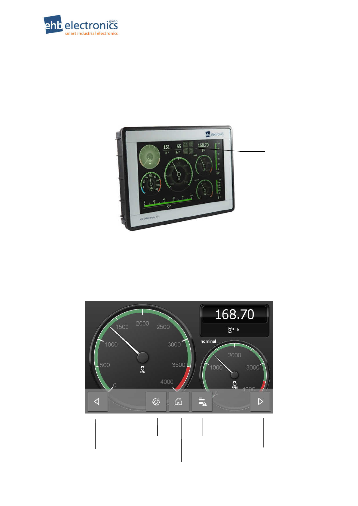
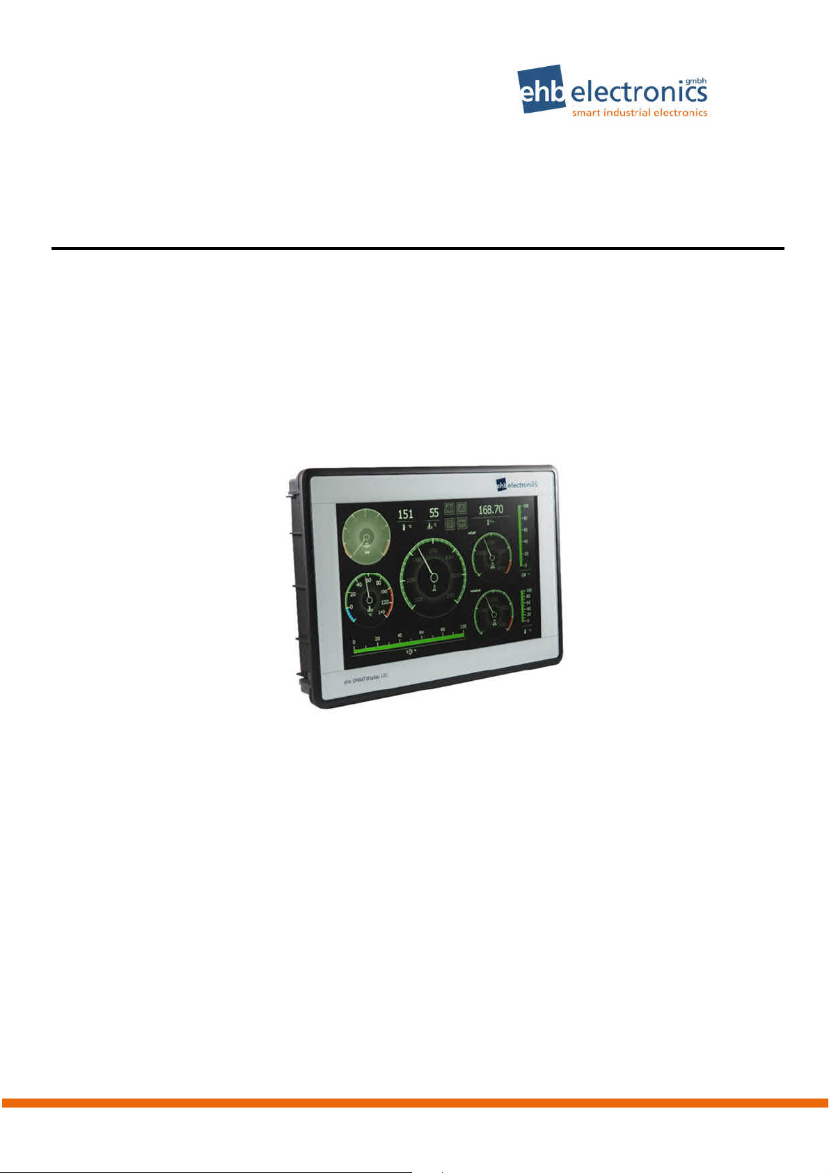
Quick guide
Overview
Operating Instructions ehb SMARTdisplay 101
Display /
Touchscreen
Functions of the Navigation Bar
To open the navigation bar, double-click on a blank area of the screen. (Double-clicking the bottom
near where the bar should be will not open it!)
Settings List of errors
Scroll left
(back)
2/19
Scroll up
Vers. 1.1 © ehb errors excepted
(page navigation)
Scroll right
(forward)
Page 3

ehb SMARTdisplay 101 Operating Instructions
Table of Contents
Quick guide ........................................................................................................................... 2
Overview ............................................................................................................................... 2
Functions of the Navigation Bar.......................................................................................... 2
Table of Contents ................................................................................................................. 3
1. General .......................................................................................................................... 4
1.1 Introduction .............................................................................................................. 4
1.2 Target Group ............................................................................................................ 4
1.3 Important Notes for the Use ..................................................................................... 5
1.4 Repair of Devices ..................................................................................................... 6
1.5 Disposal of Devices .................................................................................................. 6
2. Operation ....................................................................................................................... 7
2.1 Connection ............................................................................................................... 7
2.2 Switch On/Off ........................................................................................................... 8
2.3 Navigation of Pages ................................................................................................. 9
3. Change of Settings ..................................................................................................... 10
3.1 Setting Brightness, Contrast and Language ........................................................... 11
3.2 Set Date/Time ........................................................................................................ 11
3.3 Network (LAN) Configuration .................................................................................. 12
4. Error List ...................................................................................................................... 13
5. Communication with the PC ....................................................................................... 14
5.1 Upload of a Project / Configuration ......................................................................... 14
5.2 Update of a Project via USB .................................................................................. 15
5.3 Software Update .................................................................................................... 15
6. Wiring Diagram ........................................................................................................... 16
7. Housing Dimensions .................................................................................................. 17
8. Technical Specification .............................................................................................. 18
9. Document Information, History .................................................................................. 19
9.1 Imprint .................................................................................................................... 19
©
ehb Errors excepted
Vers. 1.2
3/19
Page 4

Operating Instructions ehb SMARTdisplay 101
1. General
1.1 Introduction
The ehb SMARTdisplay 101 unit offers a wide range of functions for monitoring and controlling all
motors and special machines that feature the CAN bus (SAE J1939). Using the special Workbench
configuration program (a software product of ehb-electronics gmbh for Windows 7 or 8), the display can
be set up individually and specific to your applications.
When errors are detected that have been received from other control units, the user is notified of them
via the display and can view them in the list of errors. Errors detected are stored with date and time and
are retained even after the ehb SMARTdisplay 101 has been restarted. More complex combinations
of parameters, data logging and control tasks can be added by means of additional, customer-specific
programs (‘Plug-Ins) to the standard software. Thus it is possible to communicate with other components
(e.g. a ehb SMARTmodul 04) via the CAN bus, to evaluate the data received and e.g. to control the
outputs of the external components.
1.2 Target Group
This documentation is addressed to service personnel for a system with built-in
ehb SMARTdisplay 101.
4/19
Vers. 1.1 © ehb errors excepted
Page 5
ehb SMARTdisplay 101 Operating Instructions
1.3 Important Notes for the Use
How to use
Safety
Storage
Shipping
Maintenance
Installation
Opening the
device
Display and
Touch Screen
The device must only be operated with the supplies provided.
Use a mild cleaning agent to clean the device.
Do not insert any objects that are not designed for the specific purpose into the
openings of the unit, as this may cause problems in the electrical components.
When operating the device, always observe general accident prevention regula-
tions.
Do not operate the ehb SMARTdisplay 101 device within range of strong electromagnetic fields. Observe the temperature specifications listed in Chapter 6.
ehb SMARTdisplay 101 devices that are not being used must be stored as described in the operating specifications.
When shipping, equipment must always be shipped in the original packaging or in
correspondingly sturdy packaging.
Use of unsuitable packaging constitutes negligence, hence rendering null and
void any claim to repairs under warranty.
The ehb SMARTdisplay 101 requires no maintenance throughout its entire service life and requires no special care.
During the installation of the device follow the directions of the manufacturers of
plugs and wire harnesses.
The ehb SMARTdisplay 101 contains any parts that can be serviced, replaced or
repaired by customers or third-party maintenance personnel.
The ehb SMARTdisplay 101 is sealed to protect against any unauthorised opening. Please note that unauthorised opening will destroy the device.
CAUTION
Do not use high-pressure cleaning equipment to clean the device.
Service personnel are to be fully instructed that high-pressure cleaners will
damage the device and void the warranty.
The touch screen may only be operated using fingers or special stylus with tip
width of at least 2mm (e.g. stylus for PDA). There is no warranty in case of
improper operation (e.g. use of knife or screw driver on touch screen).
A broken display is under no circumstances covered by warranty.
The small hole on the back of the housing below the connector cover is
for a hardware reset!
Please do not insert any object into this hole! Otherwise an important membrane
could be destroyed and water might soak into the housing of the device!
Damages of the device due to a broken membrane are not covered by
warranty.
©
ehb Errors excepted
Vers. 1.2
not
used
5/19
Page 6
Operating Instructions ehb SMARTdisplay 101
1.4 Repair of Devices
If a repair does become necessary, please ship the device to:
ehb electronics gmbh
Hans-Böckler-Str. 20
30851 Langenhagen, Germany
Please always be sure to include a written description of the problem. This will considerably simplify
troubleshooting for ehb electronics gmbh service department and allow the device to be returned
more quickly.
Or use our online service for returning the unit: www.ehbservice.de
NOTE!
ehb electronics gmbh is only liable for proper performance of tasks as well as for the suitable condition of the materials used. Further claims such as compensation for lost profits or
compensation for direct or indirect consequential damages such as loss of data are excluded
CAUTION!
Damage caused by unsuitable packaging of the device for shipping and/or unauthor-
ized intervention will void the warranty.
1.5 Disposal of Devices
Product
At the end of its service life, dispose of the product in accordance with legal requirements.
Batteries
As a consumer, you are legally required (German Battery Ordinance – Batterieverordnung) to
return all used batteries. Disposal in household waste is not permitted!
Batteries/accumulators containing hazardous substances are labelled with the symbol shown to the
left, which indicates that disposal with household waste is prohibited. The markings for the respective
heavy metals are:
Cd = Cadmium,
Hg = Mercury,
Pb = Lead.
The respective marking is found on the battery/accumulator, e.g. under the rubbish bin icon shown
above. Used batteries/accumulators can be returned free of charge to a collection point in your community or wherever batteries/accumulators are sold.
You will therefore be meeting your legal obligations and helping to protect the environment.
Thank you for your consideration.
6/19
Vers. 1.1 © ehb errors excepted
Page 7

ehb SMARTdisplay 101 Operating Instructions
2. Operation
2.1 Connection
The ehb SMARTdisplay 101 is mounted using the holders supplied and four plastic bolts. The electrical connection to the device is via a DEUTSCH plug, DT 06-12S.
Figure 1: Wiring diagram and pin assignment
Pin / Contacts
1 GND
2 Kl. 30
3 AuxIN2
4 AuxIN1
5 GND
6 GND
7 CAN1_L (Bus 1 in Application)
8 CAN1_H
9 CAN2_L (Bus 0 in Application)
10 CAN2_H
11 OUT Kl. 15F
*
12 Kl.15
*
The out pin 11 is only available on devices with serial number 372153 or higher.
For setting up and for software updates, etc., a standard USB cable can be attached to the USB port
and a standard CAT.5 patch cable connected to an Ethernet socket. For operation of the unit, cables
with the appropriate LTW connectors must be used. If you are not intending to use these interfaces,
the cap supplied should be fitted. Otherwise, the device will not meet the IP 67 protection class.
©
ehb Errors excepted
Vers. 1.2
7/19
Page 8

Operating Instructions ehb SMARTdisplay 101
2.2 Switch On/Off
When terminal 30 is active, the device is activated via terminal 15 (input), e.g. from an external ignition switch. The initial start-up procedure takes about 15 seconds while the Windows Embedded Compact 7 operating system starts up. The application then starts automatically and the home page specified by the configuration program appears.
The device is switched off by deactivating terminal 15. This places the system in a power-saving
standby mode. When the device is activated again (i.e. when terminal 15 is reactivated), the application continues. The wait time until the display appears is minimal and there is no need to wait for the
longer initial start-up procedure.
The device must be connected to steady plus (terminal 30) in case data should be saved when the
unit is switched off; i.e. so that the device is not used purely as a display. To ensure that the device
does not consume power during standby mode, you can connect it in such a way that the device is
connected by the inputs for terminals 15 and 30 to terminal 15 of the machine.
Important note: If the application requires the internal operating hours counter (OHC), it is possi-
ble that time may be lost in this OHC as it is only updated every 12 minutes or so in the flash memory.
8/19
Vers. 1.1 © ehb errors excepted
Page 9

ehb SMARTdisplay 101 Operating Instructions
2.3 Navigation of Pages
A hierarchical structure of groups can be created using the configuration program on the PC. Each
group contains one or more pages. A page group always receives at least one page - in the simplest
case, a page group is exactly one page. Every page group can, however, have more than one page.
The pages themselves contain the elements to be displayed (e.g. instruments, images, texts). Each
element can be configured so that clicking on it will move it to another group.
An example for structuring a project into pages and page groups is shown in the following illustration.
The elements of each page are indicated by small boxes (). Linking of an element with a page group
is indicated by green arrows ( ). Clicking on one of the elements from which an arrow issues
changes the display: the first page of the page group to which the arrow head points is displayed.
Note that a page group has only one entry point. It is however possible to have the same pages in different groups. This is the case in the example for groups 4 and 5.
Group 2
Group 4
Group 1
Home page
Group 5
Group 3
©
ehb Errors excepted
Vers. 1.2
9/19
Page 10

These
D
Operating Instructions ehb SMARTdisplay 101
The left/right buttons on the navigation bar allow you to browse the pages within a group.
Click (browse forward) within e.g. group 2 to move from page 2 to page 3, from page 3 to page 4
and from page 4 back to page 2.
Click (browse back) to move through the pages in the opposite direction, i.e. from page 3 to page
2 and so on.
Use to move up one level, and click it multiple times to return to the home page. In the example
shown, you thus move from group 5 back to page 5, from group 4 back to page 4, and from groups 2
and 3 click to return to page 1, which here is the home page.
3. Change of Settings
Some settings can be made or changed directly on the device via elements on the touchscreen. An
overview is given in the following table.
Menu Structure of the Setup Menu
Display Information
General
Settings
Password for protected area
Date/Time
Settings
Network
Settings
LiveView
diagnosis tool
Close
Displayed are among others date and time, available system
memory, current IP address(es), software version of modules
Setting of brightness and contrast and language
More settings may be configured after entering a password.
settings should not be modified by any operator of the machine.
The password should only be disclosed to authorized persons!
Standard password: 915066
Set date and time. Verify (and if necessary correct) the date first,
then set the time!
Here you may choose if IP address should be obtained from a
DHCP server, otherwise you may assign a static IP manually.
Not currently available.
Return to instruments view
10/19
Vers. 1.1 © ehb errors excepted
Page 11

ehb SMARTdisplay 101 Operating Instructions
3.1 Setting Brightness, Contrast and Language
In Setup, select the symbol
You can now adjust the sliders to make the screen display brighter/darker and to control the contrast.
Note that ‘wrongly’ displayed greyscales (that appear greenish or with very rough transitions) usually
do not mean that the display is faulty, but more probably indicate that the display parameters are
wrongly set. In case of doubt, try moving the bottom slider further to the left.
Select the language required by clicking the appropriate country’s flag.
3.2 Set Date/Time
This setting is only accessible via the password-protected area. The device features a real-time clock
and battery. The clock continues to run even when the device is not connected to terminal 30 (steady
plus battery). It should thus only be necessary to adjust the date or time in exceptional situations. Battery changes must be carried out by our service department.
To set the clock, first open the Setup menu by clicking the symbol on the navigation bar. First click
on and enter the password 915066. The symbols for the protected setup features will appear.
Next, click . The date/time page will appear:
©
ehb Errors excepted
Vers. 1.2
11/19
Page 12

Operating Instructions ehb SMARTdisplay 101
From left to right, set the year, month, day, hour, minute and second. Clicking on one of these areas
causes a numerical input field to appear. Type in the desired figure and press Enter to confirm. If a
valid value has been entered, this is adopted straight away. You can also cancel the input by clicking
, provided that the input line is empty. If you have already entered a figure, the top right button
is now a delete key. Each time you click this, the last digit is deleted.
If, after starting the device, you see the date 1.1.2006 and time 12:00, it is possible that there is a
problem with the clock or that the battery is exhausted. In this case, set the correct date and time and
switch the device off. Remove all cables from the rear of the unit. Wait for 20 minutes, then reconnect
the device and check the date. If this still indicates 2006, please return the device to our services department.
3.3 Network (LAN) Configuration
Network settings can only be accessed via the password-protected area. Open the Setup menu by
clicking on the navigation bar. First click on and enter the password 915066. The symbols
for the protected setup features will appear. By clicking you will see configuration options as
shown in the illustration below.
Click either the DHCP or the Static IP button, depending on whether the IP address is to be obtained
from a DHCP server or from an IP address that you type in manually. To avoid an address conflict, it is
recommended that you use the DHCP setting if a DHCP server is available in your network. Set a
static IP address to link device and PC to one another directly via a LAN cable. Then set up a static IP
address on the PC as well.
Note that the settings you make do not become active until you click the button. The settings
are then retained (even following restarts) until such time as you make a change to them and save the
changes with .
Click to move to the information page to check whether a valid IP address has been set.
“0.0.0.0” is not valid and is displayed if no network connection is present. If this occurs, check that the
cable is properly inserted into the network sockets at both ends.
12/19
Vers. 1.1 © ehb errors excepted
Page 13

ehb SMARTdisplay 101 Operating Instructions
Filter “no longer active
4. Error List
The list of errors stores errors that are received from control units via the CAN bus and can be viewed
without a password.
To open the list, click the list of errors symbol in the navigation bar.
The row of square buttons includes Delete and Detail view plus four others to filter the list displayed:
You can thus opt to view either the whole list or the active errors only, the errors that are no longer ac-
tive only or passive errors only that have been read from a motor control unit. The filter button currently active appears with a green background.
The headings in the table and the error texts to be output can be set within the configuration files.
Menu Structure of Error List
Clear Display
Detailed View
No Filter
Filter “active errors”
Clears all displayed data.
The magnifying glass may be used to show data for an error entry in a
separate page. This view may especially simplify reading of long error
texts.
All filters are deactivated. All entries are visible in the table.
Only errors that are active at the present time are shown in the list.
Only errors that are not active at the present time are shown in the list.
errors”
Filter “passive errors”
Only passive errors will be displayed.
Close
Return to settings menu
Each time the device is restarted, a new file for the list of errors can be created. This helps reduce the
risk of data loss in the event that a file could not be properly saved and its content is lost. In addition,
©
ehb Errors excepted
Vers. 1.2
13/19
Page 14

Operating Instructions ehb SMARTdisplay 101
after start-up, the last few entries of the data file previously used are copied into the start of the newly
created file. This ensures that the list always contains the latest error data, even just after a restart.
The maximum number of files that can be held in the memory of the device can be limited in the project configuration settings. The standard setting is 50 files.
5. Communication with the PC
The configuration software ehb Workbench (PC software) enables you to communicate with the device in order to transfer the display contents / project configuration. Application software update is possible by using FileZilla. The communication is via LAN (Ethernet).
ATTENTION!
To ensure that PC and device can communicate via Ethernet, both devices
must have an IP address in the same subnet. If you are unsure, please contact your
system administrator.
In the following, it is assumed that the device and PC are connected directly via Ethernet cable. The
device is configured on IP address 192.168.1.100 with the subnet mask 255.255.255.0. The PC is
configured with the fixed IP address 192.168.1.8 and the same subnet mask.
ATTENTION!
Ensure that the power supply is sufficient to last for the whole of the update and the
subsequent restart and that it will not be interrupted.
5.1 Upload of a Project / Configuration
- Run ehb Workbench
- Load a project
- In the “Extras” menu, select “Upload project data..”.
- Complete the dialogue fields as shown:
- Target IP address 192.168.1.100
- Username ftp
- Password 2070
- Config.directory /NANDFlash/config
- Program directory /NANDFlash/CANcor
- Click OK
ATTENTION!
The device must be restarted after
every upload.
- Restart the device
Note: This procedure lets you upload any project to the device. For example, the demonstration project from the file Demo-CANflex+CANschalter_Bauma2013.ehbArchive supplied with the ehb
Workbench configuration program. We therefore recommend this procedure for loading a project into
the device for the first time. In the field the device then may be updated via USB (which requires that
the project name remains the same).
14/19
Vers. 1.1 © ehb errors excepted
Page 15

ehb SMARTdisplay 101 Operating Instructions
5.2 Update of a Project via USB
To update a project, no network or PC is required on site by the machine.
Simply copy the updated .ehbArchive file onto the U:\update folder on a USB stick (change the char-
acter U to the letter used for your USB stick drive if necessary).
- Insert the USB stick into the device.
- If the stick has an LED, wait until the flashing stops. Otherwise, wait several seconds.
- Open the Setup screen
- Enter the Setup password (915066 after clicking )
- Go to the page with the button - Click the Update Config button
- If this turns GREEN, everything is OK => restart device
- If this turns RED, the archive file was not found or is corrupted.
ATTENTION!
If an archive file is found to be defective, it will be automatically deleted (if this is
possible) from the USB stick for security reasons.
5.3 Software Update
Updating the application software is only possible while application is not running. The device is designed so that stopping/terminating of the application is impossible during normal operation. Furthermore, monitoring is activated, so that the device resets itself and restarts the application if the software
crashes or the application is stopped.
To be able to install an update, you need to suppress the automatic start of the application. Connect to
the FTP-server in the device by using FileZilla. Create a new server 192.168.1.100 in the server manager with user name ftp and password 2070 and establish connection.
Rename the file „CANcorApp.exe“ in folder /NANDFlash/CANcor, e.g. to „CANcorApp_backup.exe“.
Then restart the device! After about 15 seconds the Windows® Embedded Compact 7 is booted up.
You are then on operating system level and you are able to change application and configuration.
ATTENTION!
Always create a backup of the installed application first, so that you will be able to
restore the current state!
It is advisable to first back up the files that are to be replaced.
Connect from PC with FileZilla and copy all folders in /NANDFlash including all sub-folders and all the
contained files to the PC excluding the folder /NANDFlash/Windows.
Now delete everything from „NANDFlash“ folder excluding the folder /NANDFlash/Windows!
The update (all files that go into „NANDFlash“ folder) you may copy from another directory of the PC in
the same way as creating the backup. E.g. drag the new files from a Windows Explorer window into
the FileZilla window.
After completion of the copy process wait at least 10 seconds, then re-start the device! It is possible
that the first boot up sequence after the update needs more time than usual, since still some files
might need to be extracted.
An update to Windows® Embedded Compact 7 can only be carried out by ehb electronics gmbh. No
updates are required for supplied ehb SMARTdisplay 101 devices.
©
ehb Errors excepted
Vers. 1.2
15/19
Page 16

6. Wiring Diagram
Operating Instructions ehb SMARTdisplay 101
16/19
Vers. 1.1 © ehb errors excepted
Page 17

ehb SMARTdisplay 101 Operating Instructions
7. Housing Dimensions
©
ehb Errors excepted
Vers. 1.2
17/19
Page 18

Operating Instructions ehb SMARTdisplay 101
8. Technical Specification
Parameters Conditions Limiting Values Remarks
Min. Typ. Max.
Supply voltage range UB 8V 12-24V 32V
Power consumption for
UB 8-24V
Terminal 30 (Battery +)
Power consumption for
UB 8-24V
Terminal 30 (Battery +)
Analogue inputs AuxIn1
AuxIn2
CAN bus interface 250 kbit/s CAN 2.0B, SAE J1939
Operating temperature
Storage temperature
Humidity
(non-condensing)
Vibration 6h, 10-50Hz 8g DIN EN 60068-2-6
Impact 18x, 11ms 50g DIN EN 60068-2-27
CE marking
LCD display (TFT)
Housing material
Housing dimensions
Protection class IP 67 mit Stecker
Hardware
Software
1)
with additional protection: -40°C
Remark: All values shown in italics are subject to testing.
Ignition
on
Ignition
on/off (standby)
48 h 93% DIN EN 60068-2-3
0,7mA
(UB=14V)
<5 mA
(off)
<50 mA
(standby)
-20°C 1)
-30°C
10,1” colour display
1280(W)x800(H) pixels
capacitive touchscreen
Brightness 391 cd/m²
Rear plate: aluminium
Installed H x W x D: 175 x 255 x 71.8mm
(without plug/mating plug)
Panel cut-out 125 x 85 mm
Processor: Freescale i.MX537, 800 MHz
RAM: 512 MB
ROM: 128 MB NAND flash
Windows Embedded Compact 7
2mm float glass
PA 6.6 GF 30
0,4mA
(UB=28V)
<5 mA (off)
<40 mA
(standby)
+70°C
+80°C
The product has been tested according to the following norms:
Emission. Measurement of radio radiation according to DIN EN 61000-6-4, DIN EN 61000-4-20
Robustness against electric static discharge (ESD) according to nach DIN EN 61000-4-2
Robustness against high frequency electro magnetic fields according to DIN EN 61000-4-3,
DIN EN 61000-4-20, ISO 11451-1
Robustness against quick transient disturbance (burst) according to DIN EN 61000-4-4
Robustness against peak current (surge) according to DIN EN 61000-4-5
Power consumption
during operation depends on the wiring,
supply voltage and display brightness.
Power consumption in
standby mode depends on the wiring
and supply voltage
0-20 mA or 0-10 V
configurable
according to Directive
2014/30/EU
18/19
Vers. 1.1 © ehb errors excepted
Page 19
ehb SMARTdisplay 101 Operating Instructions
Robustness against wire transmitted disturbance induced by high frequency fields according
to DIN EN 61000-4-6
Vibration according to DIN EN 60068-2-6
9. Document Information, History
Project:
Document type:
Version:
Created on:
Author:
ehb SMARTdisplay 101
Technical documentation
1.0
05.07.2017
ehb electronics gmbh, Hannover
Changes:
Version: Editing: on: by:
1.0 First edition of user manual 05.07.2017 Mö/Ak
1.0 Layout 28.11.2017 Hag
1.0 Adaption “Technical Data”: Power consumption
Adaption: Wiring diagram
1.1 Adjustment output pin 11 16.10.2019 Mx/Hag
1.2 Section 2.1 "Connection" modified 10.04.2019 Hk/Hag
23.01.2018 Mö/Hag
Hk/Hag
9.1 Imprint
Customer service:
Tel. +49-511-123207- 0
Fax. +49-511-123207-77
E-mail info@ehb-electronics.de
Hans-Böckler-Str. 20
30851 Langenhagen, Germany
©
ehb Errors excepted
www.ehb-electronics.de
www.ehbshop.de
www.ehbservice.de
Vers. 1.2
19/19
 Loading...