

Page 1
Engine controller
MCflex
Translation of the original operating instructions
Most recent revision: 08/05/2018
Version: 3.0
Page 2

2
Device Engine controller MCflex
Serial number Enter the serial number of your device here:
_ _ _ _ _ _ _ _ _ _ _ _ _ _ _ _ _ _ _ _ _ _
ehb product
number
Publisher ehb electronics gmbh
ehb5200x
Hans-Böckler-Straße 20
30851 Langenhagen
GERMANY
Tel: +49( 0)511 12 32 07 - 0
Fax: +49( 0)511 12 32 07 - 77
E-mail: info@ehb-electronics.de
www: www.ehb-electronics.de
www.ehbservice.de
www.ehbshop.de
The document is protected by copyright. All rights reserved. Copying, reproduction, translation or conversion into an electronic medium or into a machine-readable form, as a whole document or in partial sections, is not permitted without the
approval of ehb electronics gmbh.
Subject to change without notice.
Suggestions and
tips
... about this document or the device can be sent to the above address.
Last modification 08/05/2018
Version 3.0
Translation of the original operating instructions • Engine controller MCflex • 08/05/2018 • 3.0 • GB
Page 3

Table of Contents
1 DEVICE INFORMATION _________________________________________________________ 6
1.1 S
1.2 T
1.3 S
1.4 I
1.5 I
1.6 F
1.7 T
1.8 S
1.9 EU D
2 INFORMATION FOR THE READER _______________________________________________ 12
2.1 V
2.2 T
2.3 I
2.4 A
2.5 H
PECIFICATIONS ................................................................................................................... 6
YPE PLATE ......................................................................................................................... 6
COPE OF DELIVERY ............................................................................................................ 6
NTENDED USE...................................................................................................................... 7
MPROPER USE ..................................................................................................................... 7
UNCTIONAL DESCRIPTION.................................................................................................... 7
ECHNICAL DATA ................................................................................................................. 8
PARE PARTS ...................................................................................................................... 9
ECLARATION OF CONFORMITY .................................................................................... 10
ALIDITY ............................................................................................................................ 12
ARGET GROUP.................................................................................................................. 12
LLUSTRATIONS .................................................................................................................. 12
BBREVIATIONS USED ........................................................................................................ 13
IGHLIGHTING IN THE TEXT ................................................................................................. 14
2.5.1 P
2.5.2 N
2.5.3 S
2.5.4 W
2.5.5 H
ICTOGRAMS AND SYMBOLS ............................................................................. 14
AVIGATION PATH ............................................................................................ 15
AFETY INFORMATION ...................................................................................... 15
ARNINGS....................................................................................................... 15
ANDLING INSTRUCTION ................................................................................... 15
3
3 SAFETY _____________________________________________________________________ 16
3.1 S
3.2 D
3.3 L
3.4 Q
3.5 P
3.6 R
AFETY INFORMATION ........................................................................................................ 16
3.1.1 I
3.1.2 I
3.1.3 I
3.1.4 I
3.1.5 I
3.1.6 I
3.1.7 I
UTIES OF THE OPERATOR ................................................................................................. 18
OCAL REGULATIONS ......................................................................................................... 18
UALIFICATION OF PERSONNEL .......................................................................................... 19
ICTOGRAMS AND SYMBOLS ON THE DEVICE ....................................................................... 19
ESIDUAL RISK .................................................................................................................. 20
NFORMATION ABOUT OPERATIONAL SAFETY ...................................................... 16
NFORMATION ABOUT INITIAL COMMISSIONING .................................................... 16
NFORMATION ABOUT OPERATION...................................................................... 16
NFORMATION ABOUT DECOMMISSIONING AND STORAGE..................................... 16
NFORMATION ABOUT MAINTENANCE AND REPAIRS ............................................. 17
NFORMATION ABOUT ENVIRONMENTAL PROTECTION .......................................... 17
MPERMISSIBLE OPERATING CONDITIONS ........................................................... 17
4 PARTS OF THE DEVICE________________________________________________________ 22
4.1 F
4.2 D
4.3 R
4.4 B
RONT OF DEVICE .............................................................................................................. 22
ISPLAY VIEWS .................................................................................................................. 23
4.2.1 O
4.2.2 D
4.2.3 T
EAR OF DEVICE ................................................................................................................ 24
OTTOM OF DEVICE............................................................................................................ 25
PERATING PARAMETERS................................................................................. 23
AILY OPERATING DURATION ............................................................................ 24
OTAL OPERATING DURATION ........................................................................... 24
Translation of the original operating instructions • Engine controller MCflex • 08/05/2018 • 3.0 • GB
Page 4

4
5 UNPACKING, CONNECTING AND INSTALLING_____________________________________ 26
5.1 U
5.2 C
5.3 M
6 PARAMETRIZATION ___________________________________________________________34
6.1 D
6.2 N
6.3 P
7 MENUS IN PARAMETRIZATION MODE____________________________________________35
7.1 O
7.2 M
7.3 S
7.4 S
7.5 S
7.6 S
7.7 S
NPACKING........................................................................................................................ 26
ONNECTING ...................................................................................................................... 27
5.2.1 C
5.2.2 C
5.2.3 C
OUNTING ......................................................................................................................... 30
5.3.1 T
5.3.2 M
ESIGN OF THE DISPLAY IN PARAMETRIZATION MODE........................................................... 34
AVIGATING IN PARAMETRIZATION MODE ............................................................................. 34
ARAMETRIZING THE DEVICE ............................................................................................... 34
VERVIEW.......................................................................................................................... 35
AIN MENU ........................................................................................................................ 36
UBMENU – SETTINGS........................................................................................................ 36
7.3.1 [1] S
7.3.2 S
7.3.3 S
7.3.4 H
7.3.5 G
7.3.6 G
7.3.7 A
7.3.8 F
7.3.9 F
7.3.10 L
7.3.11 I
UBMENU – SERVICE.......................................................................................................... 61
7.4.1 [2] S
7.4.2 [1] S
7.4.3 [2] F
7.4.4 [3] F.L.
UBMENU – SAFETY........................................................................................................... 63
7.5.1 [3] S
7.5.2 S
7.5.3 S
UBMENU – DAILY OPERATING HOURS COUNTER ................................................................ 65
7.6.1 [4] D
7.6.2 S
UBMENU – OPERATING HOURS COUNTER .......................................................................... 65
7.7.1 [5] OHC
7.7.2 S
ONNECTION DIAGRAM AND PIN ASSIGNMENT .................................................... 27
IRCUIT DIAGRAM............................................................................................. 28
ONNECTING THE DEVICE ................................................................................. 29
ECHNICAL DRAWING........................................................................................ 30
OUNTING THE DEVICE..................................................................................... 30
ETTINGS.................................................................................................... 36
UBMENU LANGUAGE........................................................................................ 37
ENSOR SUBMENU ........................................................................................... 38
IGH-POWER OUTPUT SUBMENU ....................................................................... 40
LOW TIMES SUBMENU..................................................................................... 46
ENERATOR.ER SUBMENU................................................................................ 49
UTOSTART SUBMENU ...................................................................................... 49
AULT EVENT SUBMENU .................................................................................... 51
AULT TIMES MENU........................................................................................... 54
IMIT VALUES SUBMENU .................................................................................... 57
NPUTS/OUTPUTS SUBMENU .............................................................................. 59
ERVICE ..................................................................................................... 61
ERVICE SETTINGS ...................................................................................... 62
AULT LIST.................................................................................................. 62
DELETE ................................................................................................ 63
AFETY....................................................................................................... 63
UBMENU – PIN NUMBERS ............................................................................... 63
UBMENU – SELF-TEST .................................................................................... 64
AY COUNTER............................................................................................. 65
UBMENU – DAY COUNTER ............................................................................... 65
COUNTER ........................................................................................... 65
UBMENU – OHC – MENU ............................................................................... 66
Translation of the original operating instructions • Engine controller MCflex • 08/05/2018 • 3.0 • GB
Page 5

8 CANBUS FUNCTIONS _________________________________________________________ 67
8.1 F
8.2 M
8.3 M
UNCTIONS AND DISPLAY DEVICES ...................................................................................... 67
ESSAGE ON DEN CANBUS ............................................................................................... 67
8.2.1 PGN 61444 E
8.2.2 PGN 65253 E
8.2.3 PGN 65262 E
8.2.4 PGN 65263 E
8.2.5 PGN 65271 (R) V
8.2.6 PGN 65269 A
8.2.7 PGN 65276 D
8.2.8 PGN 65278 A
8.2.9 A
CTIVE DIAGNOSTIC TROUBLE CODES (DM1) ................................................... 69
8.2.10 PGN 42496 (R) A
ESSAGE FROM CANBUS .................................................................................................. 71
8.3.1 PGN 57344 C
LECTRONIC ENGINE CONTROLLER 1 - EEC1 ............................... 67
NGINE HOURS, REVOLUTIONS - HOURS..................................... 67
NGINE TEMPERATURE 1 - ET1.................................................... 68
NGINE FLUID LEVEL/PRESSURE 1 - EFL/P1 ................................ 68
EHICLE ELECTRICAL POWER 1 - VEP1.................................. 68
MBIENT CONDITIONS – AMB....................................................... 68
ASH DISPLAY - DD..................................................................... 68
UX WATER PUMP PRESSURE- AWP ........................................... 69
UXILIARY INPUT/OUTPUT STATUS 3 - AUXIO3 ...................... 69
AB MESSAGE 1 - CM1 ............................................................... 71
9 OPERATION _________________________________________________________________ 72
9.1 S
9.2 I
9.3 O
9.4 S
9.5 C
9.6 S
9.7 O
ETTING PULSES PER ROTATION ......................................................................................... 72
9.1.1 S
9.1.2 S
NITIAL COMMISSIONING ...................................................................................................... 73
9.2.1 I
9.2.2 C
PERATING THE DEVICE ..................................................................................................... 74
ETTING THE DEVICE MODE ................................................................................................ 74
OMMISSIONING ................................................................................................................. 75
9.5.1 R
9.5.2 S
WITCHING OFF THE DEVICE ............................................................................................... 75
PERATIONAL FAULTS........................................................................................................ 76
PEED MEASUREMENT USING AN INITIATOR (PICK UP) ........................................ 72
PEED MEASUREMENT BASED ON THE PULSES OF THE "W” TERMINAL AT PIN 13. 73
NFORMATION ABOUT INITIAL COMMISSIONING .................................................... 73
ARRYING OUT INITIAL COMMISSIONING............................................................. 74
EQUIREMENTS FOR COMMISSIONING ............................................................... 75
WITCHING ON THE DEVICE .............................................................................. 75
5
10 MAINTENANCE, REPAIR AND DISPOSAL _________________________________________ 77
10.1 I
NFORMATION ABOUT MAINTENANCE AND REPAIRS .............................................................. 77
10.2 FAQ.................................................................................................................................. 77
10.3 R
10.4 C
10.5 C
10.6 D
EPAIR .............................................................................................................................. 77
LEANING .......................................................................................................................... 78
OMMUNICATION WITH PC (OPTIONAL) ............................................................................... 78
ISPOSAL .......................................................................................................................... 78
10.6.1 D
10.6.2 D
ISPOSAL OF DEVICES...................................................................................... 78
ISPOSAL OF BATTERIES AND RECHARGEABLE BATTERIES ................................. 79
Translation of the original operating instructions • Engine controller MCflex • 08/05/2018 • 3.0 • GB
Page 6
Specifications
6
Device information
1 Device information
1.1 Specifications
Enter the serial number of your device in the field with the dashed line.
Specifications of the device
Device name Engine controller
Device type MCflex
Serial number _ _ _ _ _ _ _ _ _ _ _ _ _ _ _ _ _ _ _ _ _ _
ehb product number ehb5200x
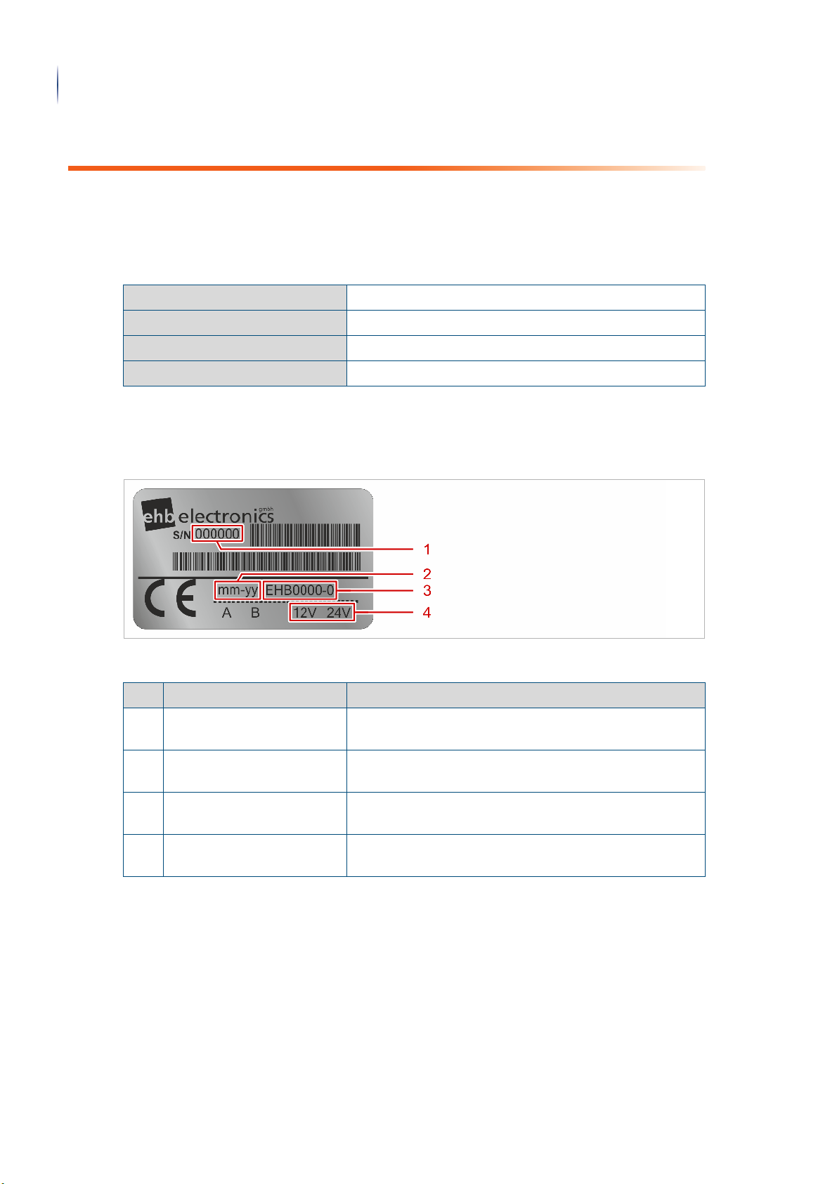
1.2 Type plate
The type plate is located on top of the housing of the device.
Representation of the type plate
Legend
No. Designation Function
1 Serial number Represents a unique and unambiguous number for
identification of the device.
2 Date of manufacturer Represents the date of manufacturer in the "month -
year” format.
3 ehb product number Represents the ehb product number of the device
series.
4 Operating voltage Represents the operating voltage with which the device
may be operated.
1.3 Scope of delivery
The following parts are included in the scope of delivery of the device:
• one device "MCflex”
• two ignition keys
• one label "Do not clean with high-pressure cleaner”
• two mounting brackets
Translation of the original operating instructions • Engine controller MCflex • 08/05/2018 • 3.0 • GB
Page 7

Intended use
Device information
1.4 Intended use
This device is exclusively used to start and monitor mechanically controlled combustion
engines in machines.
The device is for the following use only:
• starting and monitoring the mechanically controlled combustion engines of mobile and
stationary construction machines
• starting and monitoring the mechanically controlled combustion engines of inland ships
Intended use also includes compliance with all specifications in these Translation of the original operating instructions.
1.5 Improper use
Any use not mentioned in section "Intended use" (Page 7) is considered improper and may
result in personal injury and property damage.
The device is expressly not intended for the following:
• starting and monitoring the mechanically controlled combustion engines of road vehicles
• starting and monitoring the mechanically controlled combustion engines of aircraft
• starting and monitoring the mechanically controlled combustion engines of helicopters
• starting and monitoring the mechanically controlled combustion engines of deep-sea
vessels
• Unauthorised structural changes
• Unauthorised repairs
7
Info
The manufacturer is not liable for damage caused by improper use of the device. The risk for
this is borne solely by the user or operator.
The guarantee expires in the event of improper use.
1.6 Functional description
The device offers a multitude of functions for the control and monitoring of conventionally
controlled combustion engines. You can individually configure the settings for very diverse
applications and different engine variants. The device is capable of pre-glowing, by-glowing
and after-glowing the engine to up to 70 A, using time or temperature variables. Oil pressure
and engine temperature can be monitored with switches or sensors. One additional input is
provided for monitoring the generator. The operating magnet is actuated by the outputs for
excitation and pick-up winding. There is also an alarm output available. The engine can be
switched off via an "external stop” input (hood switch , cover switch / housing switch, for
example).
Translation of the original operating instructions • Engine controller MCflex • 08/05/2018 • 3.0 • GB
Page 8

Technical data
8
Device information
In the event of a fault, the display returns a corresponding message after an adjustable delay
time and an LED illuminates. If a corresponding function is programmed, the engine is
switched off. The input lock allows the clear identification of the cause of error and requires an
active acknowledgement of the fault message.
By pressing the arrow keys of the device, the operating hours, oil pressure, temperature and
number of revolutions of the engine are displayed in sequence on the two-line display. Other
parameters can be displayed using customised software.
1.7 Technical data
Electrical data
Voltage range 6 V to 32 V (typically 12 V to 24 V)
Current consumption typically 50 mA (for UB 8 V to 24 V)
Operating temperature -20°C to+70°C
Storage temperature -30°C to+80°C
Inputs Inputs:
• PIN 01 | Oil pressure as NO/NC, programmable,
switching or analogue sensor
• PIN 02 | Generator monitoring, terminal D+
• PIN 03 | Temperature as NO/NC, programmable,
switching or analogue sensor
• PIN 04 | Diverse, NO/NC
• PIN 07 | Autostart, NO/NC
• PIN 09External stop, NO/NC
• PIN 13 | Speed monitoring, terminal W, sensor or
magnetic pick-up
Outputs Outputs:
• all outputs are short circuit-proof
• PIN 02 | Generator excitation, terminal D+, 0.5 A
• PIN 06 | Freely parametrisable, 7.5 A (maximum 1s)
/ 6.0 A
• PIN 08 | Freely parametrisable, 40 A (maximum 1s)
/ 20 A
• PIN 10 | Freely parametrisable, 70 A (maximum 1s)
/ 35 A
• PIN 11 | Freely parametrisable, 40 A (maximum 1s)
/ 20 A
• PIN 12 | Freely parametrisable, 70 A (maximum 1s)
/ 35 A
• PIN 15 | Freely parametrisable, 3.5 A (maximum 1s)
/ 3.0 A
• PIN 18 | Freely parametrisable, 40 A (maximum 1s)
/ 20 A
CAN bus interface PIN 17 / 19, CAN2.0B, 250kBit, SAE J1939, EEC1, ET1,
EFL/P1, VEP1, AMB, DM1 fault alarms/auto start, speed
adjustment, optionally adaptable
Operating hours counter Integrated
Daily operating hours counter Integrated
Translation of the original operating instructions • Engine controller MCflex • 08/05/2018 • 3.0 • GB
Page 9
Spare parts
Device information
Visualisation
Display type Dot matrix LCD, transflective, dark-blue representation,
grey background
Resolution 16 x 2 characters, 5 x 8 dots per character
Brightness >1,000 cd/m²
Contrast ratio (CR) 8.24
Background lighting LED, white
Mechanical data
Housing dimensions (L x W) 72 mm x 72 mm
Installation dimensions (W x H x D)66 mm x 66 mm x 130 mm
Installation cut-out (W x H) 66 mm x 66 mm
Housing material PA 6 30 GB, black, UV-stabilised
Weight 340 g
9
Installation Mounting bracket or screw-fastening, 3 x M6
Protection class IP67
Connection Deutsch connector type HDP24-24-19PE
Test standards
Humidity DIN EN 60068-2-3
Vibration DIN EN 60068-2-6
Shock DIN EN 60068-2-27
CE marking According to Directive 2014/30/EU
Accessories
Connection cable, 19-pole, 3 m ehb2268
Deutsch plug set ehb1469
CANdongle with PC software
ehbTools
MCflex starter kit
CAN dongle, ehbTools,
connecting cable, power supply
unit
ehb5365
ehb5378
1.8 Spare parts
No spare parts are available for this device. If the device is faulty, contact the manufacturer.
Translation of the original operating instructions • Engine controller MCflex • 08/05/2018 • 3.0 • GB
Page 10

EU Declaration of Conformity
(8'HFODUDWLRQRI&RQIRUPLW\
DFFRUGLQJWR'LUHFWLYH(8$QQH[,9
'HYLFHW\SH (QJLQHFRQWUROOHU0&IOH[
HKESURGXFWQXPEHU HKE[
0DQXIDFWXUHU HKEHOHFWURQLFVJPEK
+DQV%|FNOHU6WUDH
/DQJHQKDJHQ
7KHPDQXIDFWXUHULVVROHO\UHVSRQVLEOHIRULVVXLQJWKLVGHFODUDWLRQRIFRQIRUPLW\
7KHVXEMHFWPDWWHURIWKHGHFODUDWLRQGHVFULEHGDERYHFRPSOLHVZLWKWKHUHOHYDQW
KDUPRQLVDWLRQOHJLVODWLRQRIWKH8QLRQ
(8 (OHFWURPDJQHWLFFRPSDWLELOLW\
(8 /RZYROWDJH'LUHFWLYH
(8 5R+6'LUHFWLYH
(8 :DVWH(OHFWULFDODQG(OHFWURQLF(TXLSPHQW'LUHFWLYH
(& 3URGXFW6DIHW\'LUHFWLYH
7KHGHYLFHFRPSOLHVZLWKWKHVWDQGDUGVOLVWHGEHORZ
',1(1 (OHFWURPDJQHWLFFRPSDWLELOLW\(0&3DUW*HQHULF
VWDQGDUGV(PLVVLRQVWDQGDUGIRULQGXVWULDOHQYLURQPHQWV
',1(1 (OHFWURPDJQHWLFFRPSDWLELOLW\(0&3DUW7HVWLQJDQG
PHDVXUHPHQWWHFKQLTXHV(PLVVLRQDQGLPPXQLW\WHVWLQJLQ
WUDQVYHUVHHOHFWURPDJQHWLF7(0ZDYHJXLGHV
',1(1 (OHFWURPDJQHWLFFRPSDWLELOLW\(0&3DUW7HVWLQJDQG
PHDVXUHPHQWWHFKQLTXHV(OHFWURVWDWLFGLVFKDUJHLPPXQLW\
WHVW
',1(1 (OHFWURPDJQHWLFFRPSDWLELOLW\(0&3DUW7HVWLQJDQG
PHDVXUHPHQWWHFKQLTXHV5DGLDWHGUDGLRIUHTXHQF\
HOHFWURPDJQHWLFILHOGLPPXQLW\WHVW
',1(1 (OHFWURPDJQHWLFFRPSDWLELOLW\(0&3DUW7HVWLQJDQG
PHDVXUHPHQWWHFKQLTXHV(OHFWULFDOIDVWWUDQVLHQWEXUVW
LPPXQLW\WHVW
',1(1 (OHFWURPDJQHWLFFRPSDWLELOLW\(0&3DUW7HVWLQJDQG
PHDVXUHPHQWWHFKQLTXHV6XUJHLPPXQLW\WHVW
',1(1 (OHFWURPDJQHWLFFRPSDWLELOLW\(0&3DUW7HVWLQJDQG
PHDVXUHPHQWWHFKQLTXHV,PPXQLW\WRFRQGXFWHG
GLVWXUEDQFHVLQGXFHGE\UDGLRIUHTXHQF\ILHOGV
',1(1 (QYLURQPHQWDOWHVWLQJ3DUW7HVWV7HVW)F9LEUDWLRQ
VLQXVRLGDO
,62 5RDGYHKLFOHV9HKLFOHWHVWPHWKRGVIRUHOHFWULFDOGLVWXUEDQFHV
IURPQDUURZEDQGUDGLDWHGHOHFWULFHQHUJ\3DUW*HQHUDO
SULQFLSOHVDQGWHUPLQRORJ\
10
Device information
1.9 EU Declaration of Conformity
EU Declaration of Conformity according to EMC Directive (1/2)
Translation of the original operating instructions • Engine controller MCflex • 08/05/2018 • 3.0 • GB
Page 11
7KHQRWLILHGERG\0DUWLQ3IHLO75$:,'*PE+5HIKDVSHUIRUPHGDQ
HOHFWURPDJQHWLFFRPSDWLELOLW\WHVWDQGLVVXHGWKHIROORZLQJ(8W\SHH[DPLQDWLRQ
FHUWLILFDWH
'HYLFH 0&IOH[
$FFHVVRULHV
6LJQDWRULHVIRUDQG
RQEHKDOIRI
HKEHOHFWURQLFVJPEK
+DQV%|FNOHU6WUDH
/DQJHQKDJHQ
/DQJHQKDJHQGDWH
BBBBBBBBBBBBBBBBBBBBBBBBBBBBBBBBBBBBBBBBBBBB BBBBBBBBBBBBBBBBBBBBBBBBBBBBBBBBBBBBBBBBBBBB
3ODFHGDWH %HUQG5HLQPROG0DQDJHU
EU Declaration of Conformity
Device information
11
EU Declaration of Conformity according to EMC Directive (2/2)
As soon as the device is improperly used, this declaration and the guarantee claim will expire.
Translation of the original operating instructions • Engine controller MCflex • 08/05/2018 • 3.0 • GB
Page 12

Validity
12
Information for the reader
2 Information for the reader
2.1 Validity
Safety information: Carefully read the Translation of the original operating instructions
Carefully read through these Translation of the original operating instructions before use.
Keep these Translation of the original operating instructions for future consultation.
These Translation of the original operating instructions contain information and rules of
conduct for the safe use of the device.
Please hand over the Translation of the original operating instructions when passing on the
device.
To operate the device effectively, the Translation of the original operating instructions provide
you with information on the following topics, among others:
• Connecting and mounting the device
• Putting the device into operation
• Making settings on the device
• Maintaining the device
• Disposing of the device
2.2 Target group
These Translation of the original operating instructions are intended for the operator, user and
service personnel of the machine with integrated device "MCflex”.
Info
The service personnel must have certain qualifications in order to work on or with the device.
You can find the qualification of personnel in chapter "Safety" > "Qualification of personnel"
(Page 19).
2.3 Illustrations
The illustrations in these operating instructions show the device in simplified form in some
cases.
Translation of the original operating instructions • Engine controller MCflex • 08/05/2018 • 3.0 • GB
Page 13

2.4 Abbreviations used
The following abbreviations are used in these operating instructions:
Abbreviations used
°C Degrees Celsius
A Ampere
AW Pick-up winding
bar Unit of pressure [force/area]
OHC Operating hours counter
Cd Cadmium
ECU Electronic Control Unit
FMI Failure Mode Identifier
GND Ground
h hours
Hg Mercury
Abbreviations used
Information for the reader
13
HW Excitation winding
ID Identification
PPR Pulses per rotation
kg kilogram
LCD Liquid Crystal Display
LED Light Emitting Diode
mA Milliampere
NC Normally Closed
NO Normally Opened
NTC Negative Temperature Coefficient
Pb Lead
PC Personal Computer
PTC Positive Temperature Coefficient
s second
SPN Suspect Parameter Number
rpm revolutions per minute
V Volt
ZSS Ignition starter switch
Translation of the original operating instructions • Engine controller MCflex • 08/05/2018 • 3.0 • GB
Page 14
Highlighting in the text
14
Information for the reader
2.5 Highlighting in the text
In these Translation of the original operating instructions, important information is highlighted
with pictograms, symbols or special notations. The following examples show the most important highlights.
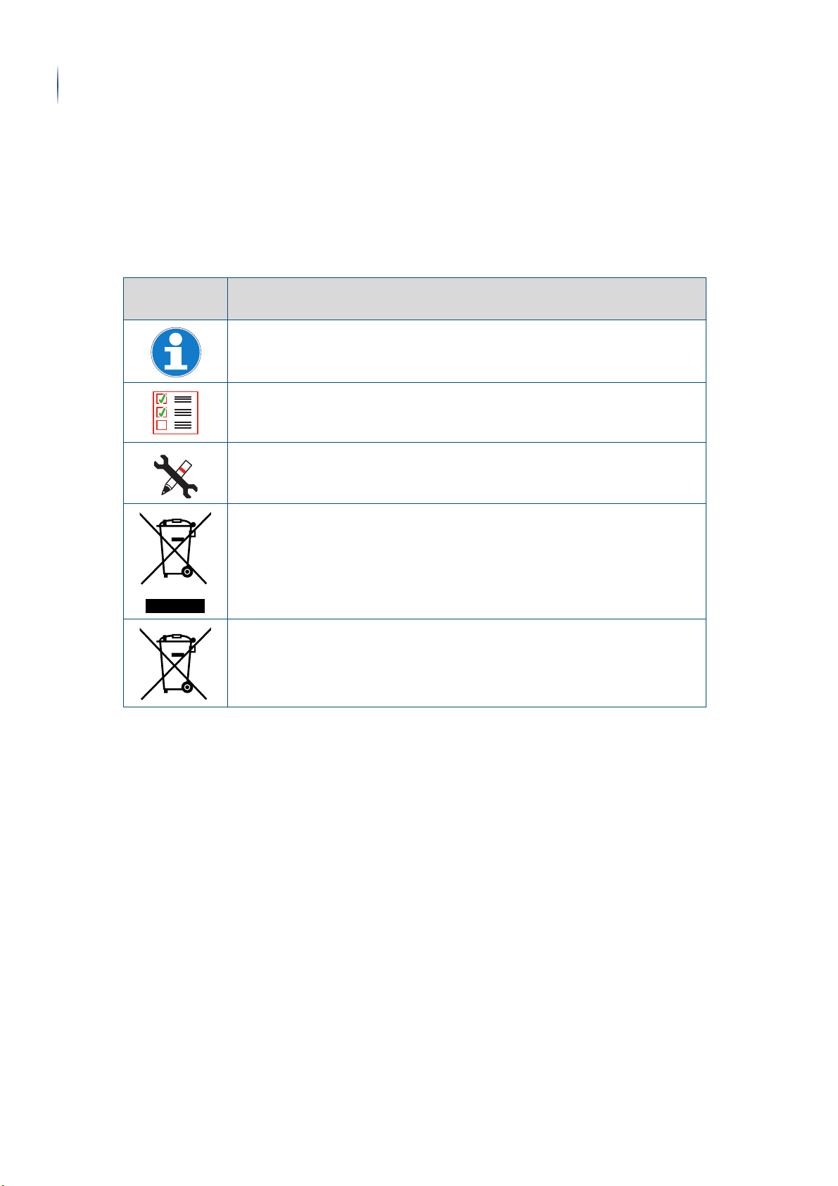
2.5.1 Pictograms and symbols
Pictograms and symbols
Pictogram /
symbol
Meaning
Further useful information.
Conditions that must be met to perform an action.
Tool or material required to perform an action.
The disposal of electrical and electronic equipment with household waste is
not permitted.
The disposal of rechargeable batteries and other batteries with household
waste is not
permitted.
Translation of the original operating instructions • Engine controller MCflex • 08/05/2018 • 3.0 • GB
Page 15
Highlighting in the text
WARNING
NOTICE
Information for the reader
2.5.2 Navigation path
The following representation helps you to navigate through the menus. Here you can see the
path of the menus that must be selected one after the other in order to reach the desired
submenu. In the digital version of the operating instructions, you can jump to the menu item
by clicking on the relevant path.
15
Main menu (page 0)
> Submenu (page 0) > Current submenu (page 0)
2.5.3 Safety information
Safety information: Special note for an informative section.
Explanation of the note.
• This item indicates measures to take the note into account.
2.5.4 Warnings
Warning of serious injuries.
Failure to follow the warning may result in serious damage to health or even death.
► The arrow indicates a precautionary measure that you must take to avert the hazard.
Warning of material damage.
Failure to observe the warning notice can result in considerable damage to the device or its
surroundings.
► The arrow indicates a precautionary measure that you must take to avert the hazard.
2.5.5 Handling instruction
Complete the following work steps: = Start of a handling instruction.
1. First step in a sequence of actions.
Required settings . . . . . . . . . . . . . .
Setting values
2. Second step in a sequence of actions.
▼ Result of this step.
» Done Handling is completed, the goal is achieved.
Translation of the original operating instructions • Engine controller MCflex • 08/05/2018 • 3.0 • GB
Page 16

Safety information
16
Safety
3 Safety
3.1 Safety information
This safety information is addressed to the operator, user and service personnel of the
device.
3.1.1 Information about operational safety
The device is safe to operate. It was built according to the current state of science and technology.
However, the device may constitute a hazard:
• if the device is used not as intended.
• if the device is improperly used.
• If the device is operated under impermissible conditions.
Safety information: Protect against unauthorised opening!
The device has a protective seal to prevent it being opened without authorisation. Note that
any unauthorised opening of the device will lead to it being irreparably damaged.
The following information applies to everyone who works on or with the device:
• Never insert any objects into the device openings not intended for this purpose. There is
a risk of interfering with the electronics.
• Protect the locking cylinder of the ignition starter switch from penetrating dirt and water.
• Only open a battery master switch in an emergency or when the engine is at standstill
and the device is switched off.
• When operating the device, comply with the general accident prevention regulations.
• Operate the device under the conditions specified by the manufacturer (see page 8:
Device information > Technical data).
• Never open the housing of the device. The device does not contain components that can
be serviced, replaced or repaired by the customer or third-party service personnel.
3.1.2 Information about initial commissioning
The following principles apply for initial commissioning:
• Make sure that the device is only connected and installed by personnel qualified for this.
• Make sure that no one can be injured when switching on the device.
3.1.3 Information about operation
Safety-conscious and precautionary behaviour of personnel avoids dangerous situations
during operation.
Observe the following points when handling the device:
• The device may only be connected and installed by personnel qualified for this. Observe
the information from the manufacturer of the plugs and cable harnesses.
• The environment must be free of interfering electrical installations (high frequency) and
electromagnetic compatibility (EMC Directive) must be observed.
• Never make any structural changes to the device.
• Only operate the device with accessories approved by the manufacturer.
3.1.4 Information about decommissioning and storage
The following principles apply for decommissioning and storage:
• Clean all dirt from the device.
• Store the device according to the specifications of the manufacturer (see page 8: Device
information > Technical data).
Translation of the original operating instructions • Engine controller MCflex • 08/05/2018 • 3.0 • GB
Page 17

Safety information
Safety
3.1.5 Information about maintenance and repairs
The following principles apply for maintenance and repairs:
• The device requires no maintenance and no special actions.
• Only clean the device with a mild cleaning agent.
• Never clean the device with a high-pressure cleaner.
• The device is to be shipped either in its original packaging or in suitable sturdy alternative
packaging. Improper packaging is regarded as negligence and results in any claims for
repair under guarantee being forfeited.
3.1.6 Information about environmental protection
Safety-conscious and precautionary behaviour of personnel avoids adverse effects on the
environment.
All packaging materials and devices are equipped with markings and test seals for proper and
professional disposal.
The following principles apply for environmentally-friendly actions:
• Always comply with the regulations for the prevention, disposal and recycling of waste.
• Always dispose of packaging materials and electrical devices and their components
through collection points or disposal companies authorised for this.
• Used electrical devices and electronic devices must not be disposed of with household
waste.
17
The devices comply with legal requirements, in particular the Electrical and Electronic Equipment Act and the REACH Regulation.
3.1.7 Impermissible operating conditions
Operational safety cannot be guaranteed under impermissible operating conditions. Always
avoid impermissible operating conditions.
Do not operate the device under the following conditions:
• Operation could injure persons.
• Objects could be damaged or destroyed unintentionally during operation.
• Malfunctions have been detected.
• Damage has been detected.
• Impermissible changes to operating parameters have been made.
• For example, the device has been modified.
Translation of the original operating instructions • Engine controller MCflex • 08/05/2018 • 3.0 • GB
Page 18

Duties of the operator
18
Safety
3.2 Duties of the operator
This chapter contains information on the duties of the operator of the machine in which the
device is installed.
It is the operator’s duty of care to plan safety measures and to check their implementation.
The following principles apply to minimise the risk of injury:
• Make sure that damaged devices are no longer used.
• Make sure that the device is installed and connected by authorised specialist personnel.
The following principles apply for faultless operation:
• Only use the device for its intended purpose.
• Only operate the device when it is in a perfect and functional condition.
• Make sure that the device is never opened by personnel. Damage caused by opening the
• Make sure that the device is properly transported and stored by personnel.
• Make sure that the device is never cleaned with a high-pressure cleaner. Give the service
Info
device will void the warranty.
personnel comprehensive instructions that cleaning with a high-pressure cleaner will
cause damage and that the warranty will be excluded.
Carry out regular checks. This allows you to ensure that these measures are actually
followed.
3.3 Local regulations
In addition to these instructions, correct operation of the device is regulated by laws and regulations.
The following regulations also apply for the operation of the device:
• Regulations for operating machines in which the device is installed (laws and regulations
not expressly mentioned here as well).
• Accident prevention regulations.
• Internal company regulations.
• Information on the device.
Translation of the original operating instructions • Engine controller MCflex • 08/05/2018 • 3.0 • GB
Page 19

Qualification of personnel
Safety
3.4 Qualification of personnel
All work on the device requires special training of the personnel.
Everyone working on the device must meet the following requirements:
• Persons between the ages of 14 and 18 may only work on and with the device under the
supervision of a person trained to use the device.
• Personally suitable for the respective activity.
• Sufficiently qualified for the respective activity.
• Trained to handle the device.
• Familiar with these operating instructions, especially with safety information and with the
sections that are relevant for the activity.
• Familiar with basic occupational safety and accident prevention regulations.
These operating instructions distinguish between the following user groups:
User groups
Personnel Qualification
19
Operating
personnel
Service
personnel
Training by the operator of the machine in which the device is installed.
The following topics must be covered in this training:
• Intended operation of the device
• Correct behaviour in the event of malfunctions, errors, damage
• Cleaning the device
• Competences and responsibilities for the activity
The required knowledge for the operating personnel is given in these
operating instructions. The operator must train the user to use the
machine in which the device is installed. Operating personnel must have
read and understood the operating instructions.
Training as a mechatronics engineer or at least equivalent training.
The tasks of the service personnel include the following activities:
• Connecting the device
• Mounting the device
• Parametrizing the device
Service personnel must have sound knowledge of the design and function of the device and must have read and understood the operating
instructions.
3.5 Pictograms and symbols on the device
Pictograms and symbols are attached to the device. The following table explains the meanings of the pictograms and symbols.
Pictograms and symbols on the device
Pictogram /
symbol
Meaning
Prohibited: Cleaning with a high-pressure cleaner is prohibited.
Translation of the original operating instructions • Engine controller MCflex • 08/05/2018 • 3.0 • GB
Page 20

Residual risk
20
Safety
3.6 Residual risk
The device is built according to the currently valid rules of technology and is safe to operate.
The device has been tested and has left the factory in a perfectly safe condition.
Residual hazards cannot be completely ruled out. Safety-conscious and precautionary behaviour of personnel avoids dangerous situations. Read and observe the safety information and
warnings to prevent risks.
Residual risks at the device and measures
Danger Cause Measure
Material damage due to
missing protective function of the starter!
Material damage due to
incorrect wiring of the
outputs!
Risk of injury due to
misuse of pin 9
(external stop) for the
emergency stop function of the engine!
Material damage due to
incorrect type of installation!
The starter of the
engine can be damaged
due to the missing
signal. The signal is
required for the integrated protective function of the starter.
If the outputs are
connected in parallel,
there is a risk that transistors may blow.
Misuse of pin 9
(external stop) for the
engine emergency stop
function may cause
serious injury at parts of
the engine. The input is
not designed for this
purpose. This can result
in delays of up to one
second.
Installation with
mounting brackets is
intended exclusively for
locations without the
influence of vibrations. If
the device with
mounting brackets is
mounted at locations
subject to vibration,
there is a risk of serious
damage to the device!
Make sure that a speed signal is
connected to pin 13 (terminal "W”).
Make sure that the transmission ratio
(PPR) and the maximum start speed are
set correctly.
Never connect the outputs in parallel.
Never use pin 9 (external stop) for the
emergency stop function of the engine!
Mount the device at locations subject to
vibration with rubber-bonded metals
(accessories).
Only carry out installation with mounting
brackets if you can ensure that no vibrations can have an effect! (For example,
in a switch cabinet)
Material damage due to
load on ignition starting
switch!
Translation of the original operating instructions • Engine controller MCflex • 08/05/2018 • 3.0 • GB
If weight is attached to
the ignition key (e.g.
heavy keychain,...),
there is a risk of
damaging the ignition
lock.
Do not hang any other weight or other
objects on the ignition key.
Page 21

Residual risks at the device and measures (cont.)
Danger Cause Measure
Residual risk
Safety
21
Material damage due to
the ingress of water!
If the device is cleaned
with a high-pressure
cleaner, there is a risk
that water ingresses in
the housing and
damages the device.
Never clean the device with a high-pressure cleaner.
Information for the operator: Instruct your
service personnel about the consequences of using high-pressure
cleaners.
Apply the supplied label "Do not clean
with high-pressure cleaner” visibly in the
immediate vicinity of the device at the
installation site.
Translation of the original operating instructions • Engine controller MCflex • 08/05/2018 • 3.0 • GB
Page 22
Front of device
22
Parts of the device
4 Parts of the device
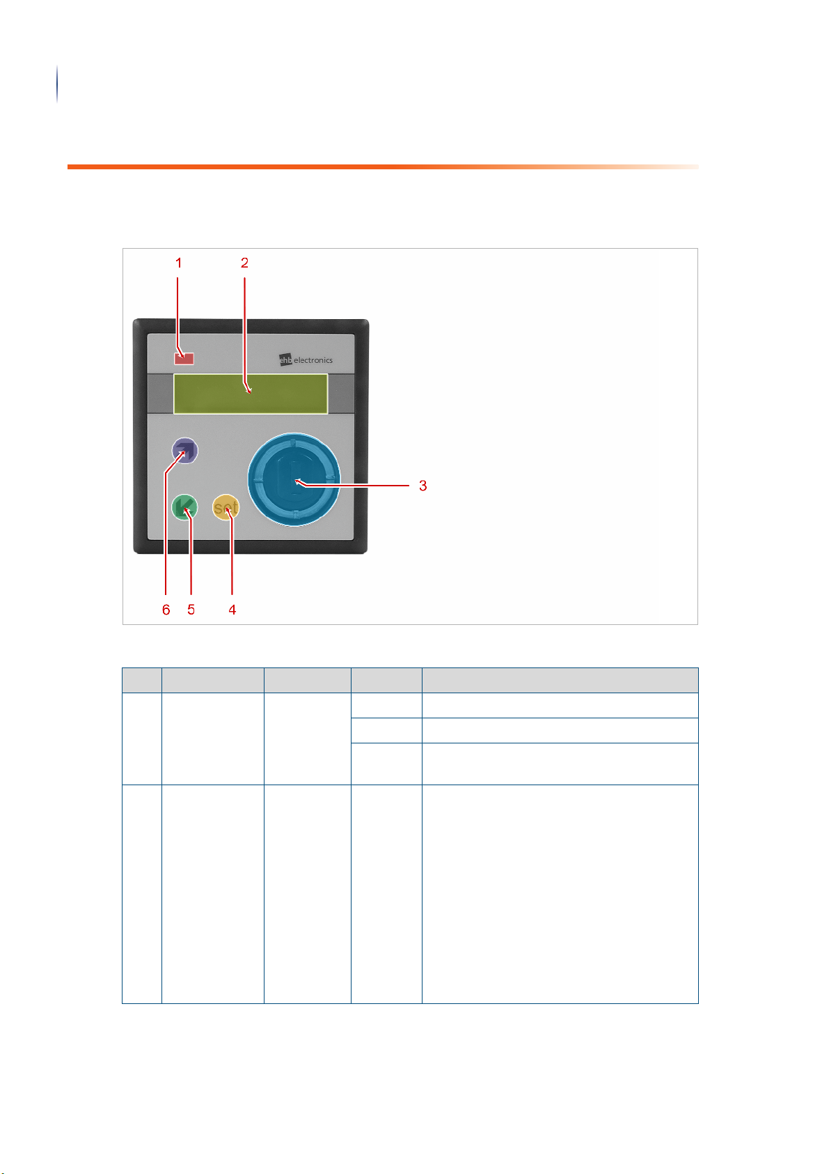
4.1 Front of device
Front of device
Legend
No. Designation Type Setting Function
1 Operation LED LED off shows that the device is switched off.
Green shows that the device is switched on.
Red shows that an error message is present on
the device.
2 Display LCD - The two-line display shows messages and
parameters during operation. Each line has
16 characters.
The following display views can be viewed
during operation:
• Operating parameters
• Daily operating hours counter
• Total operating hours counter
You can find the functions in the parametrizing mode in chapter "Parametrization" > "Design of the display in
parametrization mode" (Page 34).
Translation of the original operating instructions • Engine controller MCflex • 08/05/2018 • 3.0 • GB
Page 23
Legend (cont.)
set
ì
ì
No. Designation Type Setting Function
Display views
Parts of the device
23
3 Ignition lock Ignition
starter
switch
4 Pushbutton press Used to confirm messages.
5 Pushbutton press Used to navigate through the
6 Pushbutton press Used to navigate through the
0 The device is switched off.
1 The device is supplied with power.
The "ignition” is switched on.
A connected diesel engine pre-glows.
2 The connected engine starts.
You can find the functions in the parametrizing mode in chapter "Parametrization" > "Navigating in parametrization
mode" (Page 34).
menus/display views.
The next menu item is displayed.
You can find the functions in the para-
metrizing mode in chapter "Parametrization" > "Navigating in parametrization
mode" (Page 34).
menus/display views.
The previous menu item is displayed.
You can find the functions in the para-
metrizing mode in chapter "Parametrization" > "Navigating in parametrization
mode" (Page 34).
4.2 Display views
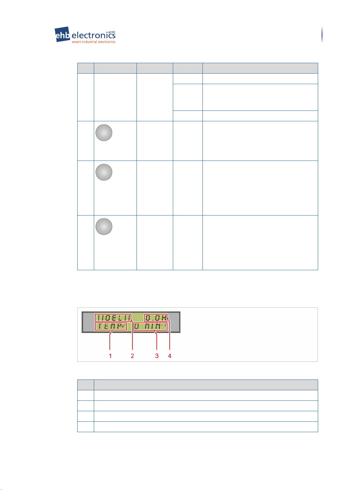
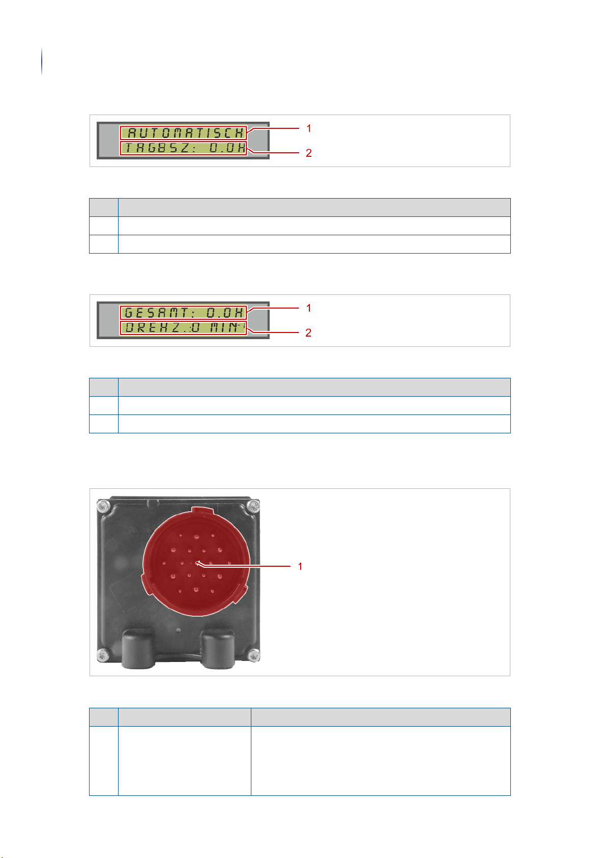
4.2.1 Operating parameters
Operating parameters
Legend
No. Function
1 Displays the current state of the engine temperature.
2 Displays the current state of the oil pressure.
3 Displays the current engine speed. (only when engine is running)
4 Displays the current daily operating duration.
Translation of the original operating instructions • Engine controller MCflex • 08/05/2018 • 3.0 • GB
Page 24
Rear of device
24
Parts of the device
4.2.2 Daily operating duration
Daily operating duration
Legend
No. Function
1 Displays the current set operating mode of the device.
2 Displays the current daily operating duration.
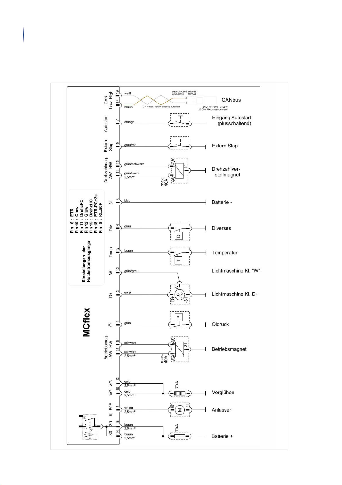
4.2.3 Total operating duration
Total operating duration
Legend
No. Function
1 Displays the total operating duration.
2 Displays the current engine speed. (only when engine is running)
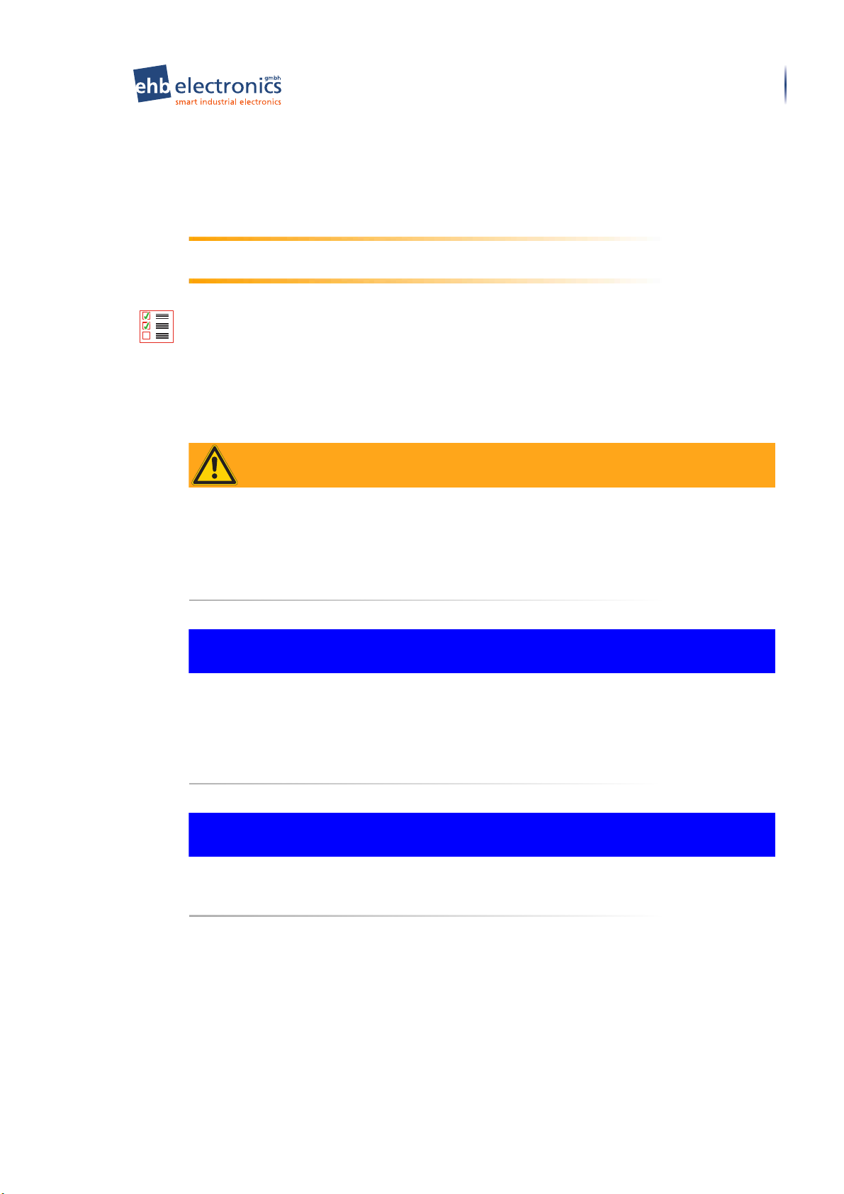
4.3 Rear of device
Rear of device
Legend
No. Designation Function
1 Device connection –
Deutsch connector
Translation of the original operating instructions • Engine controller MCflex • 08/05/2018 • 3.0 • GB
Used as a connection point for a Deutsch connector
socket housing.
You can find an example or the pin assignment in
chapter "Unpacking, connecting and installing" >
"Connection diagram and pin assignment" (Page 27).
Page 25

4.4 Bottom of device
Bottom of device
Bottom of device
Parts of the device
25
No. Designation Function
1 Threaded bushings The three threaded bushings are used to attach the
device with the aid of M6 threaded screws.
Information about installation with fastening screws can
be found in chapter ""Unpacking, connecting and
installing" > "Installation with fastening screws"
(Page 30)".
2 Mounting bracket sockets A total of four mounting bracket sockets (two additional
mounting bracket sockets are on the top of the device)
are used to attach the mounting bracket. For example,
the device can be mounted in a switch cabinet door with
the aid of the mounting brackets.
Information about installation with mounting brackets
can be found in chapter ""Unpacking, connecting and
installing" > "Installation with mounting brackets"
(Page 31)".
Translation of the original operating instructions • Engine controller MCflex • 08/05/2018 • 3.0 • GB
Page 26

Unpacking
26
Unpacking, connecting and installing
5 Unpacking, connecting and installing
5.1 Unpacking
Check the device for the following points after unpacking:
• Has any damage been found?
• Is the delivery complete? Compare the delivered parts with the information on the delivery
note.
If the device is damaged or the delivery is incomplete, inform the supplier immediately.
Carefully store any documents supplied. Enter the serial number of your device at the places
provided in these operating instructions.
Dispose of the packaging material in accordance with local regulations.
Info
Keep the original packaging in case the device needs to be shipped to the manufacturer for
maintenance at a later date.
Translation of the original operating instructions • Engine controller MCflex • 08/05/2018 • 3.0 • GB
Page 27

Connecting
Unpacking, connecting and installing
5.2 Connecting
5.2.1 Connection diagram and pin assignment
The following connection diagram and the associated table show as an example the pin
assignment for the ehb standard connection with a Deutsch connector, type HDP 26-24-19
SE.
27
Connection diagram and pin assignment
Example of the pin assignment
Pin Designation ehb wire code
Low-power contacts
1 Oil pressure green | 1 mm
2 Terminal "D+” (excitation) white | 1 mm
3 Temperature brown | 1 mm
4 Diverse grey | 1 mm
5 Terminal "31”, GND, earth blue | 1 mm
6 Operating magnet, excitation winding black | 1 mm
7 Autostart "(positive-switching)” orange | 1 mm
9 External stop grey/red | 1 mm
11 Speed adjustment pick-up winding green/white | 1 mm
13 Terminal "W” green/grey | 1 mm
15 Speed adjustment excitation winding green/black | 1 mm
2
2
2
2
2
2
2
2
2
2
2
17 CAN Low brown | twisted pair or shielded
19 CAN High white | twisted pair or shielded
High-power contacts
8 50f to starter purple | 2.5 mm
10 19/17 pre-glowing yellow | 2.5 mm
2
2
12 19/17 pre-glowing (or terminal 15 programmable) yellow | 2.5 mm2 or red 2.5 mm
14 Terminal "30”, battery + brown | 2.5 mm
16 Terminal "30”, battery + brown | 2.5 mm
18 Operating magnet, pull-in winding black | 2.5 mm
Translation of the original operating instructions • Engine controller MCflex • 08/05/2018 • 3.0 • GB
2
2
2
2
Page 28
Connecting
28
Unpacking, connecting and installing
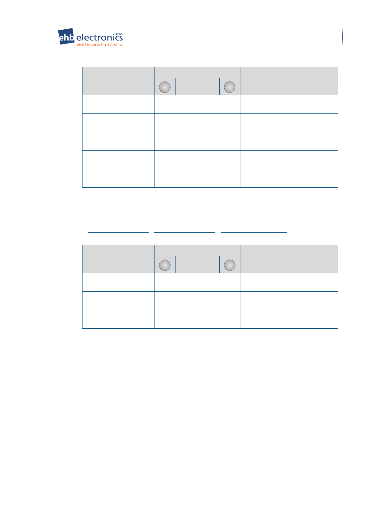
5.2.2 Circuit diagram
The following circuit diagram shows the wiring for the ehb standard connection as an
example.
Circuit diagram
Translation of the original operating instructions • Engine controller MCflex • 08/05/2018 • 3.0 • GB
Page 29
Connecting
WARNING
NOTICE
NOTICE
Unpacking, connecting and installing
5.2.3 Connecting the device
The device can be used for engine monitoring in conventional engines. For this purpose, the
engine parameters to be monitored must be appropriately connected.
Safety information: Observe the information from other manufacturers!
When connecting the device, observe the information from the manufacturer of the plugs and
cable harnesses!
Requirements:
• All switching inductors have been equipped with a free-wheeling diode.
• The connection of the main power supply to the battery terminals must be direct with a suf-
ficient cross-section.
• The connection of the main power supply is fused in accordance with regulations. You can
find additional information in chapter "Device information" > "Technical data" (Page 8).
29
Risk of injury due to misuse of pin 9 (external stop) for the emergency
stop function of the engine!
Misuse of pin 9 (external stop) for the engine emergency stop function may cause serious
injury at parts of the engine. The input is not designed for this purpose. This can result in
delays of up to one second.
► Never use pin 9 (external stop) for the emergency stop function of the engine!
Material damage due to missing protective function of the starter!
The starter of the engine can be damaged due to the missing signal. The signal is required
for the integrated protective function of the starter.
► Make sure that a speed signal is connected to pin 13 (terminal "W”).
► Make sure that the transmission ratio (PPR) and the maximum start speed are set
correctly.
Material damage due to incorrect wiring of the outputs!
If the outputs are connected in parallel, there is a risk that transistors may blow.
► Never connect the outputs in parallel.
Complete the following work steps:
1. Wire the Deutsch connector socket housing for the device according to the connection di-
agram (see page 27: Connection diagram and pin assignment).
! Note that the device must be permanently connected to terminal "30” for subsequent
operation.
2. Connect the Deutsch connector socket housing with the ‹device connection - Deutsch
connector› on the device.
» Done
Translation of the original operating instructions • Engine controller MCflex • 08/05/2018 • 3.0 • GB
Page 30

Mounting
30
Unpacking, connecting and installing
5.3 Mounting
5.3.1 Technical drawing
Technical drawing
5.3.2 Mounting the device
5.3.2.1 Installation with fastening screws
Requirements:
• The installation opening and holes for the fastening screws have been prepared and drilled
at the installation site according to the technical drawing (see page 30: Technical drawing).
• The device is connected (see page 29: Connecting the device).
Complete the following work steps:
1. Remove the Deutsch connector socket housing from the ‹device connection - Deutsch
connector› on the device.
2. Guide the cable harness with the Deutsch connector socket housing through the installation
opening.
3. Connect the Deutsch connector socket housing with the ‹device connection - Deutsch
connector› on the device.
4. Install the device at the desired location.
! For better vibration damping, you should provide a rubber buffer for each of the three
fastening points.
Translation of the original operating instructions • Engine controller MCflex • 08/05/2018 • 3.0 • GB
Page 31

Mounting
NOTICE
Unpacking, connecting and installing
5. Fasten the device from below using three M6 x 10 threaded screws
(maximum 10 mm!).
! Tighten the three M6 threaded screws by hand.
6. Apply the supplied label ‹"Do not clean with high-pressure cleaner”› visibly in the imme-
diate vicinity of the device at the installation site.
! Apply the label so that it is visible to cleaning personnel.
31
» Done
5.3.2.2 Installation with mounting brackets
Requirements:
• The installation opening has been prepared and drilled at the installation site according to
the technical drawing (see page 30: Technical drawing).
• The device is connected (see page 29: Connecting the device).
Material damage due to incorrect type of installation!
Installation with mounting brackets is intended exclusively for locations without the influence
of vibrations. If the device with mounting brackets is mounted at locations subject to vibration,
there is a risk of serious damage to the device!
► Mount the device at locations subject to vibration with rubber-bonded metals (see
page 30: Installation with fastening screws).
► Only carry out installation with mounting brackets if you can ensure that no vibrations can
have an effect! (For example, in a switch cabinet)
Translation of the original operating instructions • Engine controller MCflex • 08/05/2018 • 3.0 • GB
Page 32

Mounting
32
Unpacking, connecting and installing
Complete the following work steps:
1. Remove the Deutsch connector socket housing from the ‹device connection - Deutsch
connector› on the device.
2. Guide the cable harness with the Deutsch connector socket housing through the installation
opening.
3. Connect the Deutsch connector socket housing with the ‹device connection - Deutsch
connector› on the device.
4. Install the device at the desired location.
5. Insert the two ‹mounting brackets› in the four ‹mounting bracket sockets› on the device.
! There are two mounting bracket sockets on the top and bottom of the device.
6. Swivel the two mounting brackets against the inside of the installation opening at the instal-
lation site.
! Make sure that the mounting brackets securely clamp the device at the installation site.
Translation of the original operating instructions • Engine controller MCflex • 08/05/2018 • 3.0 • GB
Page 33

Mounting
Unpacking, connecting and installing
7. Apply the supplied label ‹"Do not clean with high-pressure cleaner”› visibly in the imme-
diate vicinity of the device at the installation site.
! Apply the label so that it is visible to cleaning personnel.
» Done
33
Translation of the original operating instructions • Engine controller MCflex • 08/05/2018 • 3.0 • GB
Page 34

Design of the display in parametrization mode
ì
ì
set
34
Parametrization
6 Parametrization
6.1 Design of the display in parametrization mode
Design of the display in parametrization mode
Legend
No. Designation Function
1 Menu line Generally the name of the relevant menu is shown in the
2 Entry line The parameters of the relevant menu are displayed and
menu line.
entered in the entry line.
6.2 Navigating in parametrization mode
Navigating in parametrization mode
Designation Function
Used to navigate through the menu.
Used to navigate through the available parameters.
Increase or decrease parameter values.
Used to select a menu to open a submenu.
Used to select an available parameter.
Used to confirm a parameter value entered.
6.3 Parametrizing the device
Requirements:
• The device is correctly mounted (see page 30: Unpacking, connecting and installing >
Mounting).
• The engine is switched off.
Complete the following work steps:
1. Press and hold the ‹set› pushbutton.
2. Turn the ‹ignition key› in the ‹ignition lock› to
▼ The device is switched on.
▼ Parametrizing mode is started.
▼ The "MENU SELECTION”* message is shown in the display.
3. Make the required settings.
! You can find a description of the menus in chapter "Menus in parametrization mode"
(Page 35).
» Done
Translation of the original operating instructions • Engine controller MCflex • 08/05/2018 • 3.0 • GB
position 1
.
Page 35

7 Menus in parametrization mode
7.1 Overview
Overview
Level 1 Level 2 Level 3
Main menu
Submenu – Settings
Overview
Menus in parametrization mode
Submenu language
Sensor submenu
High-power output
submenu
Glow times submenu
35
Submenu – Service
Submenu – Safety
Submenu – Daily operating hours counter
Generator.Er submenu
Autostart submenu
Fault event submenu
Fault times menu
Limit values submenu
Inputs/outputs submenu
[1] Service settings
[2] Fault list
[3] F.L. delete
Submenu – PIN numbers
Submenu – Self-test
Submenu – Day counter
Submenu – Operating
hours counter
Submenu – OHC – Menu
Translation of the original operating instructions • Engine controller MCflex • 08/05/2018 • 3.0 • GB
Page 36

Main menu
set
set
set
set
36
Menus in parametrization mode
7.2 Main menu
Main menu
Selection and entry options
Menu name Action Result
[1] Settings Pin No.:
Pin No.:
reset to the factory setting! All
preset values are deleted and
must be parametrized again.)
[2] Service Pin No.:
[3] Safety Pin No.:
[4] Day counter Pin No.:
[5] TOH counter Pin No.:
End! Select Programming mode is terminated.
Info
You have three attempts to enter the correct PIN no. in the prompts of the submenu. The
main menu opens automatically after three incorrect entries. If the PIN number is not known,
you have the option to terminate the query with the ignition starter switch.
1000
(factory-set)
1272
(the device is
2000
(factory-set) "Submenu – Service" (Page 61) is
3000
(factory-set) "Submenu – Safety" (Page 63) is
4000
(factory-set) "Submenu – Daily operating hours
5000
(factory-set) "Submenu – Operating hours
"Submenu – Settings" (Page 36)
is opened.
opened.
opened.
counter" (Page 65) is opened.
counter" (Page 65) is opened.
7.3 Submenu – Settings
7.3.1 [1] Settings
> Main menu (Page 36) > [1] Settings (Page 36)
[1] Settings
Selection and entry options
Menu name Action Result
[1] Language Select "Submenu language" (Page 37) is
opened.
[2] Sensors Select "Sensor submenu" (Page 38) is
opened.
[3] High-power output Select "High-power output submenu"
(Page 40) is opened.
[4] Glow times Select "Glow times submenu" (Page 46)
is opened.
[5] Generator.Er Select "Generator.Er submenu"
(Page 49) is opened.
[6] Autostart Select "Autostart submenu" (Page 49) is
opened.
Translation of the original operating instructions • Engine controller MCflex • 08/05/2018 • 3.0 • GB
Page 37
Submenu – Settings
set
set
set
set
Menus in parametrization mode
[1] Settings (cont.)
Selection and entry options
Menu name Action Result
[7] Fault event Select "Fault event submenu" (Page 51)
is opened.
[8] Fault times Select "Fault times menu" (Page 54) is
opened.
[9] Limit values Select "Limit values submenu" (Page 57)
is opened.
[10] Inputs/Outputs Select "Inputs/outputs submenu"
(Page 59) is opened.
Finish set-up Select The previous upper menu is
opened.
7.3.2 Submenu language
37
7.3.2.1 [1] Language
> Main menu (Page 36) > [1] Settings (Page 36) > [1] Language (Page 37)
[1] Language
Selection and entry options
Menu name Action Result
Language German, English, French,
Russian (optional)
Units C/bar, F/bar, C/psi, F/psi The parameter is selected and
Back Select The previous upper menu is
The parameter is selected and
saved.
saved.
opened.
Translation of the original operating instructions • Engine controller MCflex • 08/05/2018 • 3.0 • GB
Page 38

Submenu – Settings
set
set
38
Menus in parametrization mode
7.3.2.2 Descriptions of the menu entries
Descriptions of the menu entries
Description Parameter information
LANGUAGE
In this menu, the language shown can be
selected in the display.
UNITS
In this menu, the unit for temperature and
the unit for pressure can be selected.
Available languages:
• German
• English
• French
• Russian
Available units for temperature:
• C/bar
• F/bar
Available units for pressure:
• C/psi
• F/psi
7.3.3 Sensor submenu
7.3.3.1 [2] Sensors
> Main menu (Page 36) > [1] Settings (Page 36) > [2] Sensors (Page 38)
[2] Sensors
Selection and entry options
Menu name Action Result
Oil (oil pressure pin1) 0-2bar, 0-3bar, 0-5bar,
0-10bar, 0-16bar, 0-25bar
Temp. (temperature
pin 3)
Imp/rot. 0.1 - 999.9 The parameter value entered is
Terminal W: PNP / (NPN) The parameter is selected and
Back Select The previous upper menu is
KTY, PT100, PT1000,
92-027-004, 92-027-006,
92-027-016, 92-027-022,
92-027-064, 92-027-081,
LDW1603
The parameter is selected and
saved.
The parameter is selected and
saved.
saved.
saved.
opened.
Translation of the original operating instructions • Engine controller MCflex • 08/05/2018 • 3.0 • GB
Page 39

Menus in parametrization mode
7.3.3.2 Descriptions of the menu entries
Descriptions of the menu entries
Description Parameter information
OIL PRESSURE (PIN 1)
Submenu – Settings
39
In this menu, the type of oil pressure
sensor can be selected.
This requires pin 1 being set to sensor
when parametrizing the inputs and
outputs (see page 59: Inputs/outputs
submenu). This menu item is not
displayed when selecting N.C., N.O. or
Without.
TEMPERATURE (PIN 3)
In this menu, the type of temperature
sensor can be selected.
This requires pin 3 being set to sensor
when parametrizing the inputs and
outputs (see page 59: Inputs/outputs
submenu). This menu item is not
displayed when selecting N.C., N.O. or
Without.
IMP/ROT.
In this menu, the number of pulses per
rotation from the pulse generator or the
number of pole pairs of the generator
including the transmission ratio can be
set. You can find information about the
calculation of the correct parameter value
in section "Operation" > "Setting pulses
per rotation" (Page 72).
Available oil pressure ranges:
• 0-2 bar
• 0-3 bar
• 0-5 bar
• 0-10 bar
• 0-16 bar
• 0-25 bar
Available sensor types:
• KTY
• PT100, PT1000,
• 92-027-004, 92-027-006, 92-027-016, 92-
027-022, 92-027-064, 92-027-081
• LDW1603
Available input range of 0.1 to 999.9.
TERMINAL W (PIN 13)
In this menu, the input wiring of terminal
W can be set to pin 13. This value can
only be set for hardware version 8.0 or
higher.
PNP:
• 10 kΩ pull-down resistor
• Operates with a terminal W connection of a
generator, a PNP inductor or other pulse
generators.
NPN:
• connected 2.5 kΩ pull-up resistor
• Operates with a NPN inductor connected to
ground.
Translation of the original operating instructions • Engine controller MCflex • 08/05/2018 • 3.0 • GB
Page 40

Submenu – Settings
set
set
40
Menus in parametrization mode
7.3.4 High-power output submenu
7.3.4.1 [3] High-power output
> Main menu (Page 36) > [1] Settings (Page 36) > [3] High-power output (Page 40)
[3] High-power output
Selection and entry options
Menu name Action Result
Pin 6 Diverse, see section "Selec-
tion options" (Page 42).
Pin 10 Diverse, see section "Selec-
tion options" (Page 42).
Pin 11 Diverse, see section "Selec-
tion options" (Page 42).
Pin 12 Diverse, see section "Selec-
tion options" (Page 42).
Pin 15 Diverse, see section "Selec-
tion options" (Page 42).
Pin 18 Diverse, see section "Selec-
tion options" (Page 42).
Pin 8 Diverse, see section "Selec-
tion options" (Page 42).
DrzMagTime 1-99 seconds The parameter value entered is
CDownTime 0-15 minutes The parameter value entered is
ChokeTime 0-255 seconds The parameter value entered is
The parameter is selected and
saved.
The parameter is selected and
saved.
The parameter is selected and
saved.
The parameter is selected and
saved.
The parameter is selected and
saved.
The parameter is selected and
saved.
The parameter is selected and
saved.
saved.
saved.
saved.
Automatic idle 0-99 seconds The parameter value entered is
Back Select The previous upper menu is
Translation of the original operating instructions • Engine controller MCflex • 08/05/2018 • 3.0 • GB
saved.
opened.
Page 41

Menus in parametrization mode
7.3.4.2 Descriptions of the menu entries
Descriptions of the menu entries
Description Parameter information
PIN 6, PIN 10, PIN 11, PIN 12, PIN 15, PIN 18, PIN 8
Submenu – Settings
41
In this menu, the relevant function of the
selected pin of the high-power output is
adjusted.
DRZMAGTIME
In this menu, the speed magnet time can
be set. After the set time has elapsed, the
high-power outputs ‹DrehzHC› and
‹DrehzPC› are activated (see page 42:
Selection options).
CDOWNTIME
In this menu, the follow-up time and
cooling time of the engine can be set.
CHOKETIME
In this menu, the choke time when starting
the engine can be set in seconds.
All SpeedHC and speedPC functions
support this function.
This means that these functions are activated during the starting process and
remain active for the programmed time in
seconds after the engine has been
successfully started. This means more
fuel is injected when starting and for a
short time afterwards.
Detailed information about the parameters that
can be selected can be found in chapter "Selection options" (Page 42).
Available input range of 1 to 99 seconds.
Available input range of 0 to 15 minutes.
Available input range of 0 to 255 seconds.
If the value 255 is entered, the function is
switched off.
AUTOMATIC IDLE
In this menu, the delay time for deactivating the output when the signal at pin 9
drops can be set. Note that the time is
restarted at pin 9 each time the signal
drops.
Available input range of 0 to 99 seconds.
If the value 0 is entered, the speed parameter
functions. HC pin 9 as described in section
"Selection options" (Page 42).
Translation of the original operating instructions • Engine controller MCflex • 08/05/2018 • 3.0 • GB
Page 42

Submenu – Settings
42
Menus in parametrization mode
7.3.4.3 Selection options
Selection options
OFF The selected output pin of the Deutsch connector is deacti-
ETR-HC The selected output pin of the Deutsch connector has the func-
ETR-PC The selected output pin of the Deutsch connector has the func-
ETR-PC+3s The selected output pin of the Deutsch connector has the func-
vated.
tion of an operating magnet ETR excitation winding.
The operating magnet – Energise To Run (ETR) is a lifting
magnet that enables the fuel feed when live. This must be
switched on during engine operation.
This function is not activated until the start procedure.
tion of an operating magnet ETR pick-up winding.
The operating magnet ETR pick-up winding allows a short-term
activation of approximately 0.5 seconds to engage the operating magnets.
tion of an operating magnet ETR pick-up winding.
The output is activated with the starter and remains active for
another 3 seconds after the starter is switched off. This function is especially for HATZ engines.
ETS-HC The selected output pin of the Deutsch connector has the func-
tion of a stopping solenoid ETS excitation winding.
The stopping solenoid – Energised To Stop (ETS) – is a lifting
magnet requiring voltage to stop the engine.
ETS-PC The selected output pin of the Deutsch connector has the func-
tion of a stopping solenoid ETS pick-up winding.
The stopping solenoid ETS pick-up winding allows a short-term
activation of approximately 0.5 seconds to engage the stopping
solenoids.
KL.15 The selected output pin of the Deutsch connector has the func-
tion of a switched output terminal 15 of the ignition starter
switch.
After an external stop signal at pin 9, it is deactivated.
This is regardless of whether the ignition starter switch is still in
position 1.
Glow The selected output pin of the Deutsch connector has the func-
tion of a pre-glow output.
This output is then active for pre-glowing, by-glowing and after-
glowing.
Alarm The selected output pin of the Deutsch connector has the func-
tion of an alarm output. The output is then active for warnings
or fault events.
SpeedHC The selected output pin of the Deutsch connector has the func-
tion of a speed-adjusting solenoid excitation winding. The
output is automatically activated after the ‹SpeedMagTime›
has elapsed when the engine is running.
SpeedPC The selected output pin of the Deutsch connector has the func-
tion of a speed-adjusting solenoid pick-up winding. The output
is automatically activated for approx. 0.5 seconds after the
‹SpeedMagTime› has elapsed when the engine is running.
Translation of the original operating instructions • Engine controller MCflex • 08/05/2018 • 3.0 • GB
Page 43

Submenu – Settings
Menus in parametrization mode
Selection options (cont.)
Mot.Running The selected output pin of the Deutsch connector has the func-
tion of a signal output. The output is active when the engine is
switched on.
Mot.Stopped The selected output pin of the Deutsch connector has the func-
tion of a signal output. The output is active when the engine is
switched off.
SpeedHC CAN The selected output pin of the Deutsch connector has the func-
tion of a speed-adjusting solenoid excitation winding. The
output is activated and deactivated via a CANbus message
when the engine is switched on.
The CANbus message can be transmitted with the aid of an
ehb CANmodule ehb5002-14.
SpeedPC CAN The selected output pin of the Deutsch connector has the func-
tion of a speed-adjusting solenoid pick-up winding. The output
is active via a CANbus message for approximately 0.5 seconds
when the engine is switched on.
The CANbus message can be transmitted with the aid of an
ehb CANmodule ehb5002-14.
43
KL.50F The selected output pin of the Deutsch connector has the func-
tion of a starter output. The output has a direct connection to
the starter. In addition, the output has built-in starter protection.
The starter protection prevents start-up if the engine is
switched on or still stopping. This prevents damage to the
starter, pinion and engine sprocket.
ALARM_DIV The selected output pin of the Deutsch connector has the func-
tion of a signal output. The output sends the status of pin 4
(diverse).
For example, a low tank level (tank level switch) can be acoustically signalled by a horn.
KL.75 The selected output pin of the Deutsch connector has the func-
tion of a switched output terminal 75 of the MCflex ignition
starter switch.
SpeedHC Key The selected output pin of the Deutsch connector has the func-
tion of a speed-adjusting solenoid excitation winding. The
output is activated when the engine is switched on using the
‹Up arrow key› and deactivated using the ‹Down arrow key›.
SpeedPC Key The selected output pin of the Deutsch connector has the func-
tion of a speed-adjusting solenoid pick-up winding. The output
is active for approximately 0.5 seconds when the engine is
switched on using the ‹Up arrow key›.
SpeedHC Pin9 The selected output pin of the Deutsch connector has the func-
tion of a speed-adjusting solenoid excitation winding. The
output is active when the engine is switched on with a ground
signal of pin 9 (external stop). If the ground signal of pin 9 is
opened again, the output is deactivated.
This requires selecting the parameter ‹without› for pin 9. You
can select this parameter in "Inputs/outputs submenu"
(Page 59).
Translation of the original operating instructions • Engine controller MCflex • 08/05/2018 • 3.0 • GB
Page 44

Submenu – Settings
44
Menus in parametrization mode
Selection options (cont.)
SpeedPC Pin9 The selected output pin of the Deutsch connector has the func-
VG display The selected output pin of the Deutsch connector has the func-
VG Qty/ML The selected output pin of the Deutsch connector has the func-
Terminal 15* The selected output pin of the Deutsch connector has the func-
tion of a speed-adjusting solenoid pick-up winding. The output
is active when the engine is switched on with a ground signal
from pin 9 (external stop) for approximately 0.5 seconds.
This requires selecting the parameter ‹without› for pin 9. You
can select this parameter in "Inputs/outputs submenu"
(Page 59).
tion of a signal output. The output
glowing function.
tion of a signal output. The output flashes to show the preglowing function. When the engine is switched on, the output is
continually activated.
tion of a switched output terminal 15 of the ignition starter
switch. The output also remains active after a signal from pin 9
(external stop).
If the ignition starter switch is in position 0, the output is deactivated. This is also the case if the parameter ‹ON› is selected in
"Autostart submenu" (Page 49).
For example, operation with a remote control supplied by the
terminal_15* output. The function on ‹ON_15› and Autostart
input as a ‹button›.
only
displays the pre-
Fuel Pump The selected output pin of the Deutsch connector has the func-
tion to operate a fuel supply pump. The output is active when
the controller is switched on.
The output is deactivated when the engine is not switched on
after approximately 120 seconds and after an active signal
from pin 9 (external stop).
The output is deactivated if a fault is present.
Terminal 15 Auto The selected output pin of the Deutsch connector has the func-
tion of an external power supply for downstream autostart electronics.
To activate this function, the
be set (see page 74: Operation > Setting the device mode).
If the device mode is set to
vated.
StartAlarm The selected output pin of the Deutsch connector has the func-
tion of a signal output. The output is activated shortly before
the automatic start.
automatic
manual
device mode must
, this function is deacti-
Translation of the original operating instructions • Engine controller MCflex • 08/05/2018 • 3.0 • GB
Page 45

Submenu – Settings
Menus in parametrization mode
Selection options (cont.)
L.Cooler The selected output pin of the Deutsch connector has the func-
tion of a fan controller with two
temperature limit values.
The temperature is measured via pin 3 (temperature).
Factory-set temperature limit values:
• minimum 85 °C
• maximal 95 °C
Parameter 169
of 0-255 °C.
Parameter 170
of 0-255 °C.
The preset temperature limit values can be changed with the
aid of the ‹ehb Tools› software.
Terminal 50F* The selected output pin of the Deutsch connector has the func-
tion of a switched output terminal 50F. The engine can only be
switched on in the
tart).
To activate this function, the
be set (see page 74: Operation > Setting the device mode).
If the device mode is set to
vated.
for the minimum temperature in the range
for the maximum temperature in the range
automatic
device mode via pin 7 (autos-
automatic
manual
device mode must
, this function is deacti-
45
CHOKE The selected output pin of the Deutsch connector has the func-
tion of a choke output. The output becomes active when the
engine is switched on.
After the programmed ‹Choke time› has elapsed, the output is
deactivated.
Safety information: Caution!
All outputs are monitored for wire breaks. For this reason, a test voltage is applied to open
outputs with a high impedance. The functions of the outputs can be checked only when they
are under load with a test lamp, for example.
Translation of the original operating instructions • Engine controller MCflex • 08/05/2018 • 3.0 • GB
Page 46

Submenu – Settings
set
set
46
Menus in parametrization mode
7.3.5 Glow times submenu
7.3.5.1 [4] Glow times
> Main menu (Page 36) > [1] Settings (Page 36) > [4] Glow times (Page 46)
[4] Glow times
Selection and entry options
Menu name Action Result
Temp1 from -40 °C to 99 °C The parameter value entered is
Temp2 from -40 °C to 99 °C The parameter value entered is
Time1 (Temp1) 1-250 seconds The parameter value entered is
Time2 (Temp2) 1-250 seconds The parameter value entered is
After-glowing 0-1.5 times pre-glowing The parameter value entered is
saved.
saved.
saved.
saved.
saved.
Fixed time 0-250 seconds The parameter value entered is
saved.
EGR interv. 0-999 hours The parameter value entered is
saved.
EGR VG 1-120 seconds The parameter value entered is
saved.
VG Fct. OFF, int. sensor, ext. Sensor,
fixed time
Back Select The previous upper menu is
The parameter is selected and
saved.
opened.
Translation of the original operating instructions • Engine controller MCflex • 08/05/2018 • 3.0 • GB
Page 47

Menus in parametrization mode
7.3.5.2 Descriptions of the menu entries
Descriptions of the menu entries
Description Parameter information
TEMP1
Submenu – Settings
47
In this menu, the higher
limit value for temperature-dependent preglowing can be set.
TEMP2
In this menu, the lower
limit value for temperature-dependent preglowing can be set.
TIME1 (TEMP1)
In this menu, the glow time for the higher limit
value of temperature-dependent pre-glowing
of the parameter ‹Temp1› can be set.
TIME2 (TEMP2)
In this menu, the glow time for the lower limit
value of temperature-dependent pre-glowing
of the parameter ‹Temp2› can be set.
AFTER-GLOWING
In this menu, the time in which after-glowing
takes place after the engine is switched on
can be set.
The after-glow time is the result of the determined pre-glow time multiplied by the value
specified here.
Available input range of -40 °C to 99 °C.
Available input range of -40 °C to 99 °C.
Available input range of 1-250 seconds.
Available input range of 1-250 seconds.
Available input range of 0-1.5.
FIXED TIME
In this menu, the fixed glow time can be set.
This glow time is then used for the selection
of the parameter
function.
EGR INTERV.
In this menu, the interval time of the flashing
function of the glow plug can be set.
In this way, deposits can be removed from
the glow plug or helix.
EGR VG
In this menu, the glow time of the flashing
function can be set.
VG FCT.
fixed time
in the VG Fct
Available input range of 0-250 seconds.
Available input range of 0-999 hours.
Available input range of 1-120 seconds.
Translation of the original operating instructions • Engine controller MCflex • 08/05/2018 • 3.0 • GB
Page 48

Submenu – Settings
48
Menus in parametrization mode
Descriptions of the menu entries (cont.)
Description Parameter information
In this menu, the pre-glowing function can be
selected.
Example – Temperature-dependent pre-glowing
Available parameters:
•
OFF
tivated.
•
Ext. Sensor
dependent pre-glowing is activated via an
external sensor at pin 3 (temperature).
•
int. sensor
pre-glowing is activated via the internal
NTC sensor.
•
Fixed time
is activated.
| The pre-glowing function is deac-
| Temperature-
| Temperature-dependent
| A fixed pre-glowing time
Temperature-dependent pre-glowing
Designation Value
t1=Time Temp1 in seconds 10 s
t2=Time Temp2 in seconds 30 s
T1=Temp1 in ° Celsius 10 °C
T2=Temp2 in ° Celsius -30 °C
Translation of the original operating instructions • Engine controller MCflex • 08/05/2018 • 3.0 • GB
Page 49

Submenu – Settings
set
set
set
set
Menus in parametrization mode
7.3.6 Generator.Er submenu
7.3.6.1 [5] Generator.Er
> Main menu (Page 36) > [1] Settings (Page 36) > [5] Generator.Er (Page 49)
[5] Generator.Er
Selection and entry options
Menu name Action Result
Duration 0-10 seconds The parameter value entered is
saved.
Back Select The previous upper menu is
opened.
7.3.6.2 Descriptions of the menu entries
Descriptions of the menu entries
Description Parameter information
49
DURATION
In this menu, the additional time of generator excitation can be set after the engine
is switched on.
Available input range of 0-10 seconds.
If the value 0 is entered, permanent excitation of
the generator is activated.
The function is deactivated for an active signal
from pin 9 (external stop) and errors.
7.3.7 Autostart submenu
7.3.7.1 [6] Autostart
> Main menu (Page 36) > [1] Settings (Page 36) > [6] Autostart (Page 49)
[6] Autostart
Selection and entry options
Menu name Action Result
Function OFF, ON, ON_15, CAN_15 The parameter is selected and
saved.
Attempts 1-5 The parameter value entered is
saved.
Start length 1-45 seconds The parameter value entered is
saved.
Start pause 1-45 seconds The parameter value entered is
saved.
Run-on time 0-99 seconds The parameter value entered is
saved.
Back Select The previous upper menu is
opened.
Translation of the original operating instructions • Engine controller MCflex • 08/05/2018 • 3.0 • GB
Page 50

Submenu – Settings
50
Menus in parametrization mode
7.3.7.2 Descriptions of the menu entries
Descriptions of the menu entries
Description Parameter information
FUNCTION
In this menu, the autostart function can be
selected.
Available parameters:
•
OFF
| The autostart function is deactivated.
A plus signal at pin 7 (autostart) briefly activates the controller with a display message
and switches off.
•
ON
| The autostart function is activated.
With this setting, the controller can be
remotely started and switched off without the
ignition starter switch with the aid of a plus
signal at pin 7 (autostart).
•
ON_15
vated. With this setting, the controller can
only be remotely started and switched off
with the ignition starter switch in
1
and a plus signal at pin 7 (autostart).
When using a remote control, the preglowing function is suppressed when
switching on until a valid start signal is
received via the remote control.
In this case, the ignition starter switch has
the function of a main switch.
The receiver of the remote control must
provide a ‹terminal.15*› output. This
ensures that the engine cannot be switched
on without the ignition starter switch.
•
CAN_15
vated. With this setting, the controller can
only be remotely started and stopped with
the ignition starter switch in
and with a CANbus message.
| The autostart function is acti-
position
| The autostart function is acti-
position 1
ATTEMPTS
In this menu, the number of start attempts
can be set.
START DURATION
In this menu, the duration of the respective start attempt can be set.
START PAUSE
In this menu, the time between two start
attempts can be set.
RUN-ON TIME
In this menu, additional time to protect the
starter preventing a restart after the
system has recognised that the engine is
at standstill can be set.
Translation of the original operating instructions • Engine controller MCflex • 08/05/2018 • 3.0 • GB
Available input range of 1-5.
Available input range of 1-45 seconds.
Available input range of 1-45 seconds.
Available input range of 0-99 seconds.
If the value 0 is entered, the display of the Wait
until
engine stops message is deactivated.
Page 51

Submenu – Settings
set
set
Menus in parametrization mode
Info
The Autostart input is plus switching!
You can change the autostart function between automatic and manual. To change, press and
hold the SET key for at least 5 seconds.
Note that autostart is not possible if manual is selected.
7.3.8 Fault event submenu
7.3.8.1 [7] Fault event
> Main menu (Page 36) > [1] Settings (Page 36) > [7] Fault event (Page 51)
[7] Fault event
Selection and entry options
Menu name Action Result
51
Oil pressure Diverse, see section "Selec-
tion options" (Page 54).
Temperature Diverse, see section "Selec-
tion options" (Page 54).
D+ Ladesp Diverse, see section "Selec-
tion options" (Page 54).
StartSpeed Diverse, see section "Selec-
tion options" (Page 54).
UnderSpeed Diverse, see section "Selec-
tion options" (Page 54).
OverSpeed Diverse, see section "Selec-
tion options" (Page 54).
Diverse Diverse, see section "Selec-
tion options" (Page 54).
Autostart Diverse, see section "Selec-
tion options" (Page 54).
Fuel Without, With, With* The parameter is selected and
Terminal W rupture Diverse, see section "Selec-
tion options" (Page 54).
The parameter is selected and
saved.
The parameter is selected and
saved.
The parameter is selected and
saved.
The parameter is selected and
saved.
The parameter is selected and
saved.
The parameter is selected and
saved.
The parameter is selected and
saved.
The parameter is selected and
saved.
saved.
The parameter is selected and
saved.
Sleep mode Off, idle, PWRdn The parameter is selected and
saved.
Back Select The previous upper menu is
opened.
Translation of the original operating instructions • Engine controller MCflex • 08/05/2018 • 3.0 • GB
Page 52

Submenu – Settings
52
Menus in parametrization mode
7.3.8.2 Descriptions of the menu entries
Descriptions of the menu entries
Description Parameter information
OIL PRESSURE (pin 1)
In this menu, monitoring for the oil pressure can be set in the event of a fault.
TEMPERATURE (pin 3)
In this menu, monitoring for the temperature of the engine, cylinder head or
cooling water can be set in the event of a
fault.
D+ / LADESP (pin 2)
In this menu, monitoring for the charge
voltage can be set in the event of a fault.
STARTSPEED (pin 13)
In this menu, monitoring for the start
speed can be set in the event of a fault.
UNDERSPEED (pin 13)
In this menu, monitoring for the underspeed can be set in the event of a fault.
Detailed information about the parameters that
can be selected can be found in chapter "Selection options" (Page 54).
Detailed information about the parameters that
can be selected can be found in chapter "Selection options" (Page 54).
Detailed information about the parameters that
can be selected can be found in chapter "Selection options" (Page 54).
Detailed information about the parameters that
can be selected can be found in chapter "Selection options" (Page 54).
Detailed information about the parameters that
can be selected can be found in chapter "Selection options" (Page 54).
OVERSPEED (pin 13)
In this menu, monitoring for the overspeed
can be set in the event of a fault.
DIVERSE (pin 4)
In this menu, monitoring for the Diverse
input can be set in the event of a fault.
AUTOSTART (pin 7)
In this menu, monitoring for the autostart
procedure with number of failed start
attempts can be set in the event of a fault.
FUEL (no pin)
Detailed information about the parameters that
can be selected can be found in chapter "Selection options" (Page 54).
Detailed information about the parameters that
can be selected can be found in chapter "Selection options" (Page 54).
Detailed information about the parameters that
can be selected can be found in chapter "Selection options" (Page 54).
Translation of the original operating instructions • Engine controller MCflex • 08/05/2018 • 3.0 • GB
Page 53

Menus in parametrization mode
Descriptions of the menu entries (cont.)
Description Parameter information
Submenu – Settings
53
In this menu, the diagnostic function for
the fuel fault can be set in the event of a
fault.
TERMINAL W RUPTURE (pin 13)
In this menu, monitoring for terminal W
can be set in the event of a cable break.
SLEEP MODE
In this menu, the sleep function for the
battery can be set.
The sleep function protects the battery
from discharging.
Explanation of the fuel fault diagnostic function:
Oil pressure faults and underspeed faults are
detected nearly simultaneously (50% of the set
fault time). Due to an external event, for
example, such as the fuel cock closing caused
the engine to stop.
Available parameters:
•
Without
tivated.
•
With
A display message Fault: KS is displayed.
•
With*
No message is displayed.
Detailed information about the parameters that
can be selected can be found in chapter "Selection options" (Page 54).
Available parameters:
•
OFF
•
IDLE
display is switched off after a time-out and
the pin with the function ‹terminal15*›
remains active.
If the device is switched on but the engine
does not start, the display and the consumer
is switched off after a defined time.
•
PWRdn
The display is switched off after a time-out
and the pin with the function ‹terminal15*› is
deactivated.
If the device is switched on but the engine
does not start, the display and the consumer
is switched off after a defined time.
| The diagnostic function is deac-
| The diagnostic function is activated.
| The diagnostic function is activated.
| The sleep function is deactivated.
| The sleep function is activated. The
| The sleep function is activated.
Translation of the original operating instructions • Engine controller MCflex • 08/05/2018 • 3.0 • GB
Page 54

Submenu – Settings
set
set
54
Menus in parametrization mode
7.3.8.3 Selection options
Selection options
Emergency shutdown An emergency shutdown is carried out in the event of a fault.
Alarm In the event of a fault, a message is displayed or a signal is
Without Monitoring for triggering in the event of a fault of the selected
sent via the parametrized alarm output depending on the
parameter configuration.
Possible messages
• Fault: Oil pressure
• Fault: OverTemp
• Fault: LoadSp.
• Fault: StartSpeed
• Fault: UnderSpeed
• Fault: Overspeed
• Fault: Diverse
• Fault: A.Start
• Fault: Terminal W.Rupture
pin is switched off.
CDown In the event of a fault, a shutdown is performed after a defined
time.
7.3.9 Fault times menu
7.3.9.1 [8] Fault times
> Main menu (Page 36) > [1] Settings (Page 36) > [8] Fault times (Page 54)
[8] Fault times
Selection and entry options
Menu name Action Result
Oil pressure 1-10 seconds The parameter value entered is
saved.
Temp.max 1-30 seconds The parameter value entered is
saved.
LiMa D+ 1-30 seconds The parameter value entered is
saved.
Diverse 1-30 seconds The parameter value entered is
saved.
UnderSpeed 1-30 seconds The parameter value entered is
saved.
OverSpeed 1-30 seconds The parameter value entered is
saved.
DivDelay 1-250 seconds The parameter value entered is
saved.
OverVolt. 0.1-5 seconds The parameter value entered is
saved.
Terminal W.Rupture 1-30 seconds The parameter value entered is
saved.
Translation of the original operating instructions • Engine controller MCflex • 08/05/2018 • 3.0 • GB
Page 55

Submenu – Settings
set
set
Menus in parametrization mode
[8] Fault times (cont.)
Selection and entry options
Menu name Action Result
Sleep time 1-999 seconds The parameter value entered is
saved.
Ext. stop delay 1-999 seconds The parameter value entered is
saved.
Back Select The previous upper menu is
opened.
7.3.9.2 Descriptions of the menu entries
Descriptions of the menu entries
Description Parameter information
OIL PRESSURE (pin 1)
55
In this menu, the time period over which
an active oil pressure fault should be
ignored can be set. When the time has
elapsed, the alarm set in "Fault event
submenu" (Page 51) is triggered.
TEMP.MAX (pin 3)
In this menu, the time period over which
an active temperature fault should be
ignored can be set. When the time has
elapsed, the alarm set in "Fault event
submenu" (Page 51) is triggered.
LIMA D+ (pin 2)
In this menu, the time period over which
an active generator fault should be
ignored can be set. When the time has
elapsed, the alarm set in "Fault event
submenu" (Page 51) is triggered.
DIVERSE (pin 4)
In this menu, the time period over which
an active Diverse pin fault should be
ignored can be set. When the time has
elapsed, the alarm set in "Fault event
submenu" (Page 51) is triggered.
Available input range of 1-10 seconds.
Available input range of 1-30 seconds.
Available input range of 1-30 seconds.
Available input range of 1-30 seconds.
UNDERSPEED (pin 13)
In this menu, the time period over which
an active underspeed fault should be
ignored can be set. When the time has
elapsed, the alarm set in "Fault event
submenu" (Page 51) is triggered.
OVERSPEED (pin 13)
Translation of the original operating instructions • Engine controller MCflex • 08/05/2018 • 3.0 • GB
Available input range of 1-30 seconds.
Page 56

Submenu – Settings
56
Menus in parametrization mode
Descriptions of the menu entries (cont.)
Description Parameter information
In this menu, the time period over which
an active overspeed fault should be
ignored can be set. When the time has
elapsed, the alarm set in "Fault event
submenu" (Page 51) is triggered.
DIVDELAY (pin 4)
In this menu, the time period over which
an active Diverse pin fault after switching
on the engine should be ignored can be
set. When the time has elapsed, the alarm
set in "Fault event submenu" (Page 51)
for ‹pin 4 (diverse)› is triggered.
Example:
A water pressure switch is connected to
‹pin 4 (diverse)›. This is then the time
required by a water pump to draw in
ground water and to build water pressure.
OVERVOLTAGE(pin 14/16)
In this menu, the time period over which
an active overvoltage fault should be
ignored can be set. When the time has
elapsed a Fault: F.Ue.Sp. message is
displayed.
TERMINAL W.RUPTURE (pin 13)
Available input range of 1-30 seconds.
Available input range of 1-250 seconds.
Available input range of 0.1-5 seconds.
In this menu, the time period over which
an active missing speed signal fault
should be ignored can be set. When the
time has elapsed a Fault: Terminal
W.Rupture message is displayed.
SLEEP TIME
In this menu, the time over which the
display or device should be switched on
when inactive can be parametrized. After
the time has elapsed, the device enters
the selected ‹Sleep mode› "Fault event
submenu" (Page 51).
EXT. STOP DELAY
In this menu, the time period over which
an ‹External stop signal› when switching
on the engine should be ignored can be
set.
Available input range of 1-30 seconds.
Available input range of 1-999 seconds.
Available input range of 1-999 seconds.
Translation of the original operating instructions • Engine controller MCflex • 08/05/2018 • 3.0 • GB
Page 57

Submenu – Settings
set
set
Menus in parametrization mode
7.3.10 Limit values submenu
7.3.10.1 [9] Limit values
> Main menu (Page 36) > [1] Settings (Page 36) > [9] Limit values (Page 57)
[9] Limit values
Selection and entry options
Menu name Action Result
57
Oil min 0.1-2.0 bar (for each sensor
type, see [2] Sensors
(Page 38).
Temp. max from 0 °C to 160 °C The parameter value entered is
StartSpeed 100-9,990 rpm The parameter value entered is
UnderSpeed 100-9,990 rpm The parameter value entered is
OverSpeed 100-9,990 rpm The parameter value entered is
Max.BattVolt 10-50 V The parameter value entered is
Back Select The previous upper menu is
The parameter value entered is
saved.
saved.
saved.
saved.
saved.
saved.
opened.
Translation of the original operating instructions • Engine controller MCflex • 08/05/2018 • 3.0 • GB
Page 58

Submenu – Settings
58
Menus in parametrization mode
7.3.10.2 Descriptions of the menu entries
Descriptions of the menu entries
Description Parameter information
OIL MIN
In this menu, the limit value for the
minimum oil pressure can be set.
This requires pin 1 being set to sensor
when parametrizing the inputs and
outputs (see page 59: Inputs/outputs
submenu). This menu item is not
displayed when selecting N.C., N.O. or
Without.
If not reached, the alarm set in "Fault
event submenu" (Page 51) is triggered.
TEMP. MAX
In this menu, the limit value for the
maximum engine temperature can be set.
This requires pin 3 being set to sensor
when parametrizing the inputs and
outputs (see page 59: Inputs/outputs
submenu). This menu item is not
displayed when selecting N.C., N.O. or
Without.
If exceeded, the alarm set in "Fault event
submenu" (Page 51) is triggered.
STARTSPEED
Available input range of 0.1-2.0 bar (for each
sensor type, see [2] Sensors (Page 38).
Available input range from 0 °C to 160 °C.
In this menu, the limit value for the start
speed can be set.
If exceeded, the output terminal 50F (pin
8) is deactivated.
If the start speed is not reached, the alarm
set in "Fault event submenu" (Page 51) is
triggered.
UNDERSPEED
In this menu, the limit value for the
minimum speed can be set.
If not reached, the alarm set in "Fault
event submenu" (Page 51) is triggered.
OVERSPEED
In this menu, the limit value for the
maximum speed can be set.
If exceeded, the alarm set in "Fault event
submenu" (Page 51) is triggered.
MAX.BATTVOLT
Available input range of 100-9,990 rpm.
Available input range of 100-9,990 rpm.
Available input range of 100-9,990 rpm.
Translation of the original operating instructions • Engine controller MCflex • 08/05/2018 • 3.0 • GB
Page 59

Menus in parametrization mode
set
set
Descriptions of the menu entries (cont.)
Description Parameter information
Submenu – Settings
59
In this menu, the limit value for the
maximum overvoltage present can be set.
If this overvoltage is exceeded due to, for
example, a load dump caused by battery
isolation, the controller protects itself by
shutting down and returns a fault.
Available input range of 10-50 V.
7.3.11 Inputs/outputs submenu
7.3.11.1 [10] Inputs/Outputs
> Main menu (Page 36) > [1] Settings (Page 36) > [10] Inputs/Outputs (Page 59)
[10] Inputs/Outputs
Selection and entry options
Menu name Action Result
Ext.Stop Without, N.O., N.C. The parameter is selected and
saved.
Diverse Without, N.O., N.C. The parameter is selected and
saved.
Autostart Switch, tip switch, tip
switch_SS
The parameter is selected and
saved.
Alarm Without, Constant, Interval The parameter is selected and
saved.
Oil Without, N.O., N.C., sensor The parameter is selected and
saved.
Temp Without, N.O., N.C., sensor The parameter is selected and
saved.
D+ Without, With The parameter is selected and
saved.
Cable pull Without, With The parameter is selected and
saved.
CAN address 0-256 The parameter value entered is
saved.
Back Select The previous upper menu is
opened.
Translation of the original operating instructions • Engine controller MCflex • 08/05/2018 • 3.0 • GB
Page 60

Submenu – Settings
60
Menus in parametrization mode
7.3.11.2 Descriptions of the menu entries
Descriptions of the menu entries
Description Parameter information
EXT.STOP
In this menu, the ‹Ext. Stop› input (pin 9)
can be set.
DIVERSE
In this menu, the ‹Diverse› input (pin 4)
can be set.
AUTOSTART
In this menu, the ‹Autostart› input (pin 7)
can be set.
Available parameters:
• Without | Without query
• N.O. | N.O.
• N.C. | N.C.
Available parameters:
• Without | Without query
• N.O. | N.O.
• N.C. | N.C.
Available parameters:
•
Switch
plus signal at the ‹Autostart› input (pin 7).
When the switch opens, the engine switches
off.
•
Button
plus signal at the ‹Autostart› input (pin 7).
When the switch opens, the engine remains
switched on. The engine is switched off by
the ‹Ext.Stop› (pin 9), ‹Ignition starter
switch› or ‹SET key› input.
•
Tip switch_SS
engine is switched on via a plus signal at the
‹Autostart› input (pin 7). The engine is
switched off with an additional plus signal at
the ‹Autostart› input (pin 7).
| The engine is switched on via a
| The engine is switched on via a
(current surge) | The
ALARM
In this menu, the alarm output can be set. Available parameters:
• Without | Without query
• Period | Continual
• Interval | Intermittent
OIL
In this menu, the ‹Oil› input (pin 1) can be
set.
TEMP
In this menu, the ‹Temp› input (pin 3) can
be set.
D+
Available parameters:
• Without | Without query
• N.O. | N.O.
• N.C. | N.C.
• Sensor
Available parameters:
• Without | Without query
• N.O. | N.O.
• N.C. | N.C.
• Sensor
Translation of the original operating instructions • Engine controller MCflex • 08/05/2018 • 3.0 • GB
Page 61

Menus in parametrization mode
set
set
Descriptions of the menu entries (cont.)
Description Parameter information
Submenu – Service
61
In this menu, monitoring of the generator
(pin 2) can be set.
CABLE PULL
In this menu, the cable pull function can
be set.
The changed starting conditions for a start
with cable pull compared to a start with
ignition starter switch is automatically
taken into account by the controller.
CAN ADDRESS
In this menu, the CAN address of the
device can be set.
Available parameters:
• Without | Without query
• With | With query
Available parameters:
• Without | Without query
• With | With query
Available input range of 0-256.
If the value 256 is entered, the function is deacti-
vated.
7.4 Submenu – Service
7.4.1 [2] Service
> Main menu (Page 36) > [2] Service (Page 61)
[2] Service
Selection and entry options
Menu name Action Result
[1] Service settings Select The "[1] Service settings"
(Page 62) submenu is opened.
[2] Fault list Select The "[2] Fault list" (Page 62)
submenu is opened.
[3] F.L. delete Select The "[3] F.L. delete" (Page 63)
submenu is opened.
End Select The previous upper menu is
opened.
Translation of the original operating instructions • Engine controller MCflex • 08/05/2018 • 3.0 • GB
Page 62

Submenu – Service
set
set
set
set
62
Menus in parametrization mode
7.4.2 [1] Service settings
> Main menu (Page 36) > [2] Service (Page 61) > [1] Service settings (Page 62)
[1] Service settings
Selection and entry options
Menu name Action Result
Oil@ 50 The parameter is selected and
saved.
Interval: OFF, 50, 100, …,
1000 (steps of 50 up to 1000)
Service completed The service interval is acknowl-
LUFI@ 50 The parameter is selected and
Interval: OFF, 50, 100, …,
1000 (steps of 50 up to 1000)
Service completed The service interval is acknowl-
KSFI@ 50 The parameter is selected and
Interval: OFF, 50, 100, …,
1000 (steps of 50 up to 1000)
Back Select The previous upper menu is
Service completed The service interval is acknowl-
The parameter is selected and
saved.
edged and reset.
saved.
The parameter is selected and
saved.
edged and reset.
saved.
The parameter is selected and
saved.
edged and reset.
opened.
7.4.3 [2] Fault list
> Main menu (Page 36) > [2] Service (Page 61) > [2] Fault list (Page 62)
[2] Fault list
Selection and entry options
Menu name Action Result
Error log Scroll using the arrow keys. The error messages saved in the
device are displayed.
End Select The previous upper menu is
opened.
Translation of the original operating instructions • Engine controller MCflex • 08/05/2018 • 3.0 • GB
Page 63

Submenu – Safety
set
set
set
set
set
set
Menus in parametrization mode
7.4.4 [3] F.L. delete
> Main menu (Page 36) > [2] Service (Page 61) > [3] F.L. delete (Page 63)
[3] F.L. delete
Selection and entry options
Menu name Action Result
Delete error log Select The error messages saved in the
device are deleted.
End Select The previous upper menu is
opened.
7.5 Submenu – Safety
7.5.1 [3] Safety
> Main menu (Page 36) > [3] Safety (Page 63)
[3] Safety
Selection and entry options
63
Menu name Action Result
[2] PIN numbers Select "Submenu – PIN numbers"
(Page 63) is opened.
[3] Self-test Select "Submenu – Self-test" (Page 64)
is opened.
End Select The previous upper menu is
opened.
7.5.2 Submenu – PIN numbers
7.5.2.1 [2] PIN numbers
> Main menu (Page 36) > [3] Safety (Page 63) > [2] PIN numbers (Page 63)
[2] PIN numbers
Selection and entry options
Menu name Action Result
[1] SETTINGS from 0000 to 9999 The parameter value entered is
saved.
[2] SERVICE from 0000 to 9999 The parameter value entered is
saved.
[3] SAFETY from 0000 to 9999 The parameter value entered is
saved.
[4] DAY COUNTER from 0000 to 9999 The parameter value entered is
saved.
[5] OHC from 0000 to 9999 The parameter value entered is
saved.
Back Select The previous upper menu is
opened.
Translation of the original operating instructions • Engine controller MCflex • 08/05/2018 • 3.0 • GB
Page 64

Submenu – Safety
set
set
64
Menus in parametrization mode
7.5.2.2 Descriptions of the menu entries
Descriptions of the menu entries
Description Parameter information
SETTINGS
In this menu, the PIN number for
Submenu – Settings can be set.
SERVICE
In this menu, the PIN number for
Submenu – Service can be set.
SAFETY
In this menu, the PIN number for
Submenu – Safety can be set.
DAY COUNTER
In this menu, the PIN number for
Submenu – Daily operating hours counter
can be set.
OHC
In this menu, the PIN number for
Submenu – Operating hours counter can
be set.
7.5.3 Submenu – Self-test
A four digit PIN number in the range of 0000 to
9999 must always be assigned.
A four digit PIN number in the range of 0000 to
9999 must always be assigned.
A four digit PIN number in the range of 0000 to
9999 must always be assigned.
A four digit PIN number in the range of 0000 to
9999 must always be assigned.
A four digit PIN number in the range of 0000 to
9999 must always be assigned.
7.5.3.1 [3] Self-test
> Main menu (Page 36) > [3] Safety (Page 63) > [3] Self-test (Page 64)
[3] Self-test
Selection and entry options
Menu name Action Result
Self-test NO, YES The parameter is selected and
saved.
Back Select The previous upper menu is
opened.
7.5.3.2 Descriptions of the menu entries
Descriptions of the menu entries
Description Parameter information
SELF-TEST
In this menu, the self-test function can be set. Available parameters:
•
NO
| The self-test function is activated.
• YES | The self-test function is deacti-
vated.
Translation of the original operating instructions • Engine controller MCflex • 08/05/2018 • 3.0 • GB
Page 65
Submenu – Daily operating hours counter
set
set
set
set
set
set
Menus in parametrization mode
7.6 Submenu – Daily operating hours counter
7.6.1 [4] Day counter
> Main menu (Page 36) > [4] Day counter (Page 65)
[4] Day counter
Selection and entry options
Menu name Action Result
**Day counter** Select The "Submenu – Day counter"
(Page 65) submenu is opened.
7.6.2 Submenu – Day counter
7.6.2.1 **Day counter**
> Main menu (Page 36) > [4] Day counter (Page 65) > **Day counter** (Page 65)
**Day counter**
Selection and entry options
65
Menu name Action Result
Delete YES, NO The parameter is selected and
saved.
7.6.2.2 Descriptions of the menu entries
Descriptions of the menu entries
Description Parameter information
DELETE
In this menu, the daily operating hours
counter can be reset.
Available parameters:
•
NO
| The daily operating hours counter
is not reset.
• YES | The daily operating hours counter
is reset.
7.7 Submenu – Operating hours counter
7.7.1 [5] OHC counter
> Main menu (Page 36) > [5] OHC counter (Page 65)
[5] OHC counter
Selection and entry options
Menu name Action Result
***OHC Menu*** Select The "Submenu – OHC – Menu"
(Page 66) submenu is opened.
Translation of the original operating instructions • Engine controller MCflex • 08/05/2018 • 3.0 • GB
Page 66

Submenu – Operating hours counter
set
set
66
Menus in parametrization mode
7.7.2 Submenu – OHC – Menu
> Main menu (Page 36) > [5] OHC counter (Page 65) > ***OHC Menu*** (Page 66)
7.7.2.1 ***OHC Menu***
***OHC Menu***
Selection and entry options
Menu name Action Result
Delete Select The operating hours counter is
Setting from 00000 to 99999 The parameter value entered is
Back Select The previous upper menu is
7.7.2.2 Descriptions of the menu entries
Descriptions of the menu entries
Description Parameter information
deleted. The system is reset.
saved.
opened.
DELETE
In this menu, the operating hours counter
can be deleted.
SETTING
In this menu, the operating hours counter
can be set.
Select with the SET button to delete the operating hours counter.
Available input range of 00000 to 99999.
Translation of the original operating instructions • Engine controller MCflex • 08/05/2018 • 3.0 • GB
Page 67

8 CANbus functions
8.1 Functions and display devices
All measured values and fault messages of the device are output on the CANbus. The device
behaves similar to an ECU with source address 0. The measured values are thus compatible
with many standard CANbus display devices.
The compatible ehb electronics devices include ehb SMARTdisplay 30, ehb SMARTdisplay
43, ehb SMARTdisplay 70, ehb SMARTdisplay 101, CANarmatur.
8.2 Message on den CANbus
The device supports the following CANbus functions according to the SAE J1939 250 kbit
29 bit identifier of address 00h (standard):
• PGN 61444 Electronic Engine Controller 1 - EEC1 (Page 67)
• PGN 65253 Engine Hours, Revolutions - HOURS (Page 67)
• PGN 65262 Engine Temperature 1 - ET1 (Page 68)
• PGN 65263 Engine Fluid Level/Pressure 1 - EFL/P1 (Page 68)
• PGN 65271 (R) Vehicle Electrical Power 1 - VEP1 (Page 68)
• PGN 65269 Ambient Conditions – AMB (Page 68)
• PGN 65276 Dash Display - DD (Page 68)
• PGN 65278 Aux Water Pump Pressure- AWP (Page 69)
• Active Diagnostic Trouble Codes (DM1) (Page 69)
• PGN 42496 (R) Auxiliary Input/Output Status 3 - AUXIO3 (Page 69)
Functions and display devices
CANbus functions
67
8.2.1 PGN 61444 Electronic Engine Controller 1 - EEC1
SPN 190 Engine Speed
Example:
0CF00400 8 FF FF FF 79 CC FF FF FF every 10ms (speed = 6543.1 RPM )
The measured speed at pin 13 is used here.
8.2.2 PGN 65253 Engine Hours, Revolutions - HOURS
SPN 247 Engine Total Hours of Operation
Example:
18FEE500 8 A6 05 2C 93 00 00 00 00 every 1000ms (operating hours = 123456789, 1 h )
The total operating duration determined for the speed at pin 13 is sent here.
Translation of the original operating instructions • Engine controller MCflex • 08/05/2018 • 3.0 • GB
Page 68

Message on den CANbus
68
CANbus functions
8.2.3 PGN 65262 Engine Temperature 1 - ET1
SPN 110 Engine Coolant Temperature
SPN 175 Engine Oil Temperature 1
Example:
18FEEE00 8 7D FF C0 2C FF FF FF FF every 1000ms (coolant = 85 °C oil temp. = 85 °C )
Both temperatures are determined and sent via the sensor at pin 13.
When using an external temperature switch, they are sent as a N.C or N.O for the OK value
"40 °C” and for the overtemperature value "120 °C” depending on the switch position and
programming.
8.2.4 PGN 65263 Engine Fluid Level/Pressure 1 - EFL/P1
SPN 100 Engine Oil Pressure
Example:
18FEEF00 8 FF FF FF BC FF FF FF FF every 1000ms (oil pressure = 7.5 bar )
When using an oil pressure switch at pin 1, N.O. or N.C. is sent for a lack of oil pressure
0.0 bar and for the existing oil pressure 5.0 bar depending on the switch position and
programming.
8.2.5 PGN 65271 (R) Vehicle Electrical Power 1 - VEP1
SPN 168 Battery Potential / Power Input 1
Example:
18FEF700 8 FF FF FF FF 3A 02 FF FF every 1000ms (battery voltage = 28.5 V)
Here the voltage of the power supply at pin 14 and pin 16 is sent.
8.2.6 PGN 65269 Ambient Conditions – AMB
SPN 171 Ambient Air Temperature
Example:
18FEF500h 8 FF FF FF 00 25 FF FF FF every 1000ms (internal temperature= 23 °C)
Here the temperature value of the internal NTC sensor is used.
8.2.7 PGN 65276 Dash Display - DD
SPN 96 Fuel Level
Example:
18FEFC00h 8 FF 7D FF FF FF FF FF FF every 1000ms (50%)
IMPORTANT: Note concerning CANbus function!
This message is only sent when the "parameter 167” special function is programmed to "1”. In
this case, pin 1 is used as a tank sensor input (0 Ω to 180 Ω) and pin 4 as the oil pressure
switch input. This setting can currently only be made in conjunction with a CANdongle and
ehbTools.
Translation of the original operating instructions • Engine controller MCflex • 08/05/2018 • 3.0 • GB
Page 69

Message on den CANbus
CANbus functions
8.2.8 PGN 65278 Aux Water Pump Pressure- AWP
SPN 73 Auxiliary Pump Pressure
Example:
18FEFE00h 8 7D FF FF FF FF FF FF FF every 1000ms (5 bar)
IMPORTANT: Note concerning CANbus function!
This message is only sent when the "parameter 167” special function is programmed to "2”. In
this case, pin 1 is used as a water sensor input (0 Ohm to 180 Ohm) and pin 4 as an oil pressure switch input. This setting can currently only be made in conjunction with a CANdongle
and ehbTools.
8.2.9 Active Diagnostic Trouble Codes (DM1)
Active faults with SPN and FMI number. In the first data byte, the lamp status byte is transmitted containing the information for the Red Stop Lamp and the Amber Warning Lamp.
The following states of the lamp status byte are possible:
• 00h = All Lamps Off
• 04h = Amber Warning Lamp in warning fault setting
• 10h = Red Stop Lamp in shut-down fault setting
69
Example (no errors):
18FECA00 8 00 00 00 00 00 00 00 00 every 1000ms SPN 0 FMI 0 No Error
Examples (in the event of an error):
18FECA00 8 10 00 64 00 07 01 00 00 oil pressure SPN 100 FMI 7 Engine Oil Pressure
18FECA00 8 10 00 6E 00 07 01 00 00 temperature SPN 110 FMI 7 Eng.Coolant Temperature
18FECA00 8 10 00 A7 00 07 01 00 00 DPlus SPN 167 FMI 7 Charging Sys. Potential
18FECA00 8 10 00 BD 02 07 01 00 00 Diverse SPN 701 FMI 7 Auxiliary I/O 1
18FECA00 8 04 00 BE 00 11 01 00 00 underspeed SPN 190 FMI 17 Engine Speed
18FECA00 8 10 00 BE 00 0F 01 00 00 Overspeed SPN 190 FMI 15 Engine Speed
18FECA00 8 10 00 60 00 07 01 00 00 Fuel SPN 96 FMI 7 Fuel Level
18FECA00 8 10 00 75 06 13 01 00 00 CANbus Info SPN 1653 FMI 19 CANmodule Start/Stop
18FECA00 8 10 00 A8 00 0F 01 00 00 Overvoltage SPN 168 FMI 15 Battery Potential
18FECA00 8 10 00 BE 00 07 01 00 00 KL.W Cable Break SPN 190 FMI 7 Engine Speed
18FECA00 8 04 00 93 03 0E 01 00 00 Service Due SPN 915 FMI 14 Service Delay
18FECA00 8 10 00 60 00 0D 01 00 00 Tank SPN 96 FMI 13 Fuel Level *
18FECA00 8 10 00 49 00 0D 01 00 00 Water Pressure SPN 96 FMI 13 Water Pressure *
*IMPORTANT: Note on CANbus functions!
This message is only sent when the "parameter 167” special function is programmed. This
setting can currently only be made in conjunction with a CANdongle and ehbTools.
8.2.10 PGN 42496 (R) Auxiliary Input/Output Status 3 - AUXIO3
Internal states of the device for the internal evaluation, by a CANmodule for example. Parameter Group Number:
42496 (0xA600) STATUS I/O 00=AUS 01=AN 11=NOT AVAILABLE
Translation of the original operating instructions • Engine controller MCflex • 08/05/2018 • 3.0 • GB
Page 70

Message on den CANbus
70
CANbus functions
Internal states
Pos. Length Param-
1.1 2 bits Auxiliary I/O #52 3875 PIN 1 / OIL
1.3 2 bits Auxiliary I/O #51 3874 PIN 2 / OD+
1.5 2 bits Auxiliary I/O #50 3873 PIN 3 / TEMP
1.7 2 bits Auxiliary I/O #49 3872 PIN 4 / DIV
2.1 2 bits Auxiliary I/O #56 3879 PIN 7 / Autostart
2.3 2 bits Auxiliary I/O #55 3878 Pin 9 / External Stop
2.5 2 bits Auxiliary I/O #54 3877 Internal terminal 15
2.7 2 bits Auxiliary I/O #53 3876 Internal terminal 50
3.1 2 bits Auxiliary I/O #60 3883 Internal Key Up
3.3 2 bits Auxiliary I/O #59 3882 Internal Key Down
3.5 2 bits Auxiliary I/O #58 3881 Internal Key Set
Name SPN
eter/Pin
3.7 2 bits Auxiliary I/O #57 3880 Internal Key Keyless
4.1 2 bits Auxiliary I/O #64 3887 Output PIN 2 (excitation)
4.3 2 bits Auxiliary I/O #63 3886 Output PIN 8 (50F)
4.5 2 bits Auxiliary I/O #62 3885 Output PIN 6
4.7 2 bits Auxiliary I/O #61 3884 Output PIN 10
5.1 2 bits Auxiliary I/O #68 3891 Output PIN 11
5.3 2 bits Auxiliary I/O #67 3890 Output PIN 12
5.5 2 bits Auxiliary I/O #66 3889 Output PIN 15
5.7 2 bits Auxiliary I/O #65 3888 Output PIN 18
6.1 2 bits Auxiliary I/O #72 3895 Output PIN 7 (signal/autostart)
6.3 2 bits Auxiliary I/O #71 3894 Fct. Motor at standstill
6.5 2 bits Auxiliary I/O #70 3893 Fct. Motor running
6.7 2 bits Auxiliary I/O #69 3892 Fct. Start
7.1 2 bits Auxiliary I/O #76 3899 Fct. Excitation
7.3 2 bits Auxiliary I/O #75 3898 Fct. Pre-glow
7.5 2 bits Auxiliary I/O #74 3897 Fct. Magnet HW
7.7 2 bits Auxiliary I/O #73 3896 Fct. Magnet AW
8.1 2 bits Auxiliary I/O #80 3903 Fct. SpeedHW
8.3 2 bits Auxiliary I/O #79 3902 Fct. SpeedAW
8.5 2 bits Auxiliary I/O #78 3901 Fct. SpeedHW CAN
8.7 2 bits Auxiliary I/O #77 3900 Fct. SpeedAW CAN
Translation of the original operating instructions • Engine controller MCflex • 08/05/2018 • 3.0 • GB
Page 71

Message from CANbus
CANbus functions
8.3 Message from CANbus
The device supports the following CANbus functions according to the SAE J1939 250 kbit
29 bit identifier of address 00h (standard):
• PGN 57344 Cab Message 1 - CM1 (Page 71)
8.3.1 PGN 57344 Cab Message 1 - CM1
SPN 1653-1655 Vehicle Limiting Speed Governor byte 5, bit 3-8
SPN 1656 Engine Automatic Start Enable Switch, byte 6, bit 7-8
Example:
0CE00003 8 FF FF FF FF 47 3F FF FF
Byte 5: 0x47=LowSpeed | 0x53=HighSpeed
Byte 6: 0x3F=Stop | 0x7F=Start
71
Translation of the original operating instructions • Engine controller MCflex • 08/05/2018 • 3.0 • GB
Page 72

Setting pulses per rotation
72
Operation
9 Operation
9.1 Setting pulses per rotation
The speed of an engine corresponds to the number of crankshaft rotations per minute. In
combustion engines, the speed can be taken from the "W" terminal of the generator. There is
a potential for inaccuracy due to the V-belt slip.
An initiator (pick up), on the other hand, returns absolute values (comply with the manufacturer's installation instructions). In both cases, the term frequency is used. The frequency
(pulses per second) of these pulses is proportional to the engine speed.
The value determined must then be set in chapter "Menus in parametrization mode" >
"Sensor submenu" (Page 38) for the menu item I
• Speed measurement using an initiator (pick up) (Page 72)
• Speed measurement based on the pulses of the "W” terminal at pin 13 (Page 73)
9.1.1 Speed measurement using an initiator (pick up)
MP/ROT before initial commissioning.
The initiator must be at right angles to a rotating metal part. The metal part must be directly
connected to the crankshaft of the engine (for example: belt pulley or flywheel). In this way,
holes or protrusions, for example, are detected by screw heads. The distance must be the
same and within the detection range of the initiator. When installing the initiator, ensure that
multiple pulses are emitted for each engine revolution per crankshaft revolution. The number
of pulses should not be too low as this would result in a low resolution. This method is suitable
for applications requiring an accurate measurement of the speed or if the generator does not
have a "W” terminal. The optimum values are between 4 and 16 pulses.
Translation of the original operating instructions • Engine controller MCflex • 08/05/2018 • 3.0 • GB
Page 73

Initial commissioning
Diameter of the belt pulley of the crankshaft
Diameter of the belt pulley of the generator
Number of pole fingers of the generator
2
Operation
9.1.2 Speed measurement based on the pulses of the "W” terminal at pin 13
The calculation of the pulses per rotation (PPR) results from the transmission ratio of the
generator to the crankshaft (i) multiplied by the number of pole pairs (NP).
PPR= i x NP
73
Representation of pole fingers on a generator
9.2 Initial commissioning
The device is put into operation for the first time during initial commissioning. Pay attention to
any malfunctions that may occur.
9.2.1 Information about initial commissioning
Pay attention to the following points during initial commissioning:
• Is the device properly connected? - see chapter "Unpacking, connecting and installing" >
"Connecting the device" (Page 29).
• Is the device properly mounted? - see chapter "Unpacking, connecting and installing" >
"Mounting the device" (Page 30).
• Are the fuses at the electrical connection correctly dimensioned? - see chapter "Device
information" > "Technical data" (Page 8).
Translation of the original operating instructions • Engine controller MCflex • 08/05/2018 • 3.0 • GB
Page 74

Operating the device
74
Operation
9.2.2 Carrying out initial commissioning
Requirements:
• All notes about initial commissioning have been checked and performed (see page 73: In-
formation about initial commissioning).
Complete the following work steps:
1. Set the ‹pulses per rotation› (see page 72: Operation > Setting pulses per rotation).
2. Set the other required ‹parameters› (see page 34: Parametrization > Parametrization).
3. Switch on the ‹device› (see page 75: Switching on the device).
4. Check whether the ‹device› functions according to your settings.
? The device doesn’t function?
► Try to rectify the functional faults according to the troubleshooting table (see page 76:
Operational faults).
► If necessary, contact the manufacturer.
5. Switch off the ‹device› (see page 75: Switching off the device).
» Done
9.3 Operating the device
Pay attention to possible malfunctions during operation of the device.
If you notice a malfunction, stop operation immediately. Contact the manufacturer.
9.4 Setting the device mode
The following action describes how to change the device mode from
manual
Requirements:
• The device is switched on (see page 75: Switching on the device).
Complete the following work steps:
. The changeover from
manual
to
automatic
is achieved in the same way.
1. Use the ‹up arrow› pushbutton to navigate to the following menu:
automatic
to
2. Press and hold the ‹set› pushbutton for
▼ The operating mode is changed from
» Done
Translation of the original operating instructions • Engine controller MCflex • 08/05/2018 • 3.0 • GB
5 seconds.
automatic
to
manual
.
Page 75

Commissioning
NOTICE
Operation
9.5 Commissioning
In this chapter you can find information about commissioning the device.
9.5.1 Requirements for commissioning
Before putting the device into operation, you must ensure that you can answer "Yes" to the
following questions:
• Can no one be injured during the operation of the device?
• Do I know what to do in the event of a malfunction?
9.5.2 Switching on the device
Requirements:
• The requirements for commissioning have been met (see page 75: Requirements for com-
missioning).
Material damage due to load on ignition starting switch!
If weight is attached to the ignition key (e.g. heavy keychain,...), there is a risk of damaging
the ignition lock.
► Do not hang any other weight or other objects on the ignition key.
75
Complete the following work steps:
1. Insert the ‹ignition key› in the ‹ignition lock›.
2. Turn the ‹ignition key› clockwise to
▼ Terminal 15 is activated.
3. Turn the ‹ignition key› clockwise and hold it in
▼ The engine is started.
▼ The operating LED lights up green.
position 1
position 2
.
.
? The combustion engine does not start or error messages are displayed?
► Release the ignition key and repeat the step.
► Try to rectify the functional faults according to the troubleshooting table (see page 76:
Operational faults).
► If necessary, contact the manufacturer.
4. Release the ‹ignition key›.
▼ The ignition key is automatically set to
» Done
position 1
.
9.6 Switching off the device
Complete the following work steps:
1. Turn the ‹ignition key› anticlockwise to
position 0
2. Remove the ‹ignition key› from the ‹ignition lock›.
» Done
Translation of the original operating instructions • Engine controller MCflex • 08/05/2018 • 3.0 • GB
.
Page 76

Operational faults
76
Operation
9.7 Operational faults
Possible faults are listed in the following troubleshooting table.
Troubleshooting table
Possible fault Possible cause Remedy
The device does not
switch on.
The engine starts when
switched on but not
when started.
The controller does not
respond to the input
signals.
The engine speed fluctuates widely.
A measurement at the
output shows a transistor turned on
although it should have
a high resistance.
The supply voltage is connected with the
wrong polarity. The reverse polarity
protection prevents damage to the electronics but does not replace the correct
polarity of the connection lines.
The lines for terminal 15 and terminal 50
were reversed during connection.
The inputs are not connected to ground.
The controller cannot detect plus signals.
There is a fault in the wiring for the
generator (the generator is not energised). As a result, no speed is sent by
the generator (terminal "W”).
The cabling on the inductor is faulty.
The installation of the inductor is faulty.
No load is connected to the output. The
Open-Load-Detection behaves like a low
resistance transistor.
Swap the connection
cables of the supply
line.
Swap the lines for
terminal 15 and terminal
50.
Connect the inputs to
ground.
Repair the cables.
Connect a load to the
output.
Translation of the original operating instructions • Engine controller MCflex • 08/05/2018 • 3.0 • GB
Page 77

Information about maintenance and repairs
Maintenance, repair and disposal
10 Maintenance, repair and disposal
10.1 Information about maintenance and repairs
Safety information: Protect against unauthorised opening!
The device has a protective seal to prevent it being opened without authorisation. Note that
any unauthorised opening of the device will lead to it being irreparably damaged.
The device requires no maintenance and no special actions.
Never open the housing of the device. The device does not contain components that can be
serviced, replaced or repaired by the customer or third-party service personnel.
10.2 FAQ
If you have any questions about the device or are looking for solutions to problems, please
look in the FAQs:
77
www.ehb-electronics.de/service/faq
The FAQs are continually updated. If your question cannot be answered in the FAQs, please
contact the manufacturer.
10.3 Repair
Safety information: Invalidation of the guarantee!
Damage arising from improper packaging of the device for shipping and unauthorised intervention will invalidate the guarantee.
Should the device require repair work, please return it to the manufacturer:
ehb electronics gmbh
Hans-Böckler-Straße 20
30851 Langenhagen
GERMANY
Please make sure that you include a written fault description. This ehb electronics gmbhwill
considerably facilitate the fault identification process for the service personnel and thus
ensure a quicker turnaround time for the device.
Alternatively you can use our online service for returning devices: www.ehbservice.de
The device is to be shipped either in its original packaging or in suitable sturdy alternative
packaging. Improper packaging is regarded as negligence and results in any claims for repair
under guarantee being forfeited.
Info
ehb electronics gmbh assumes liability only for the proper execution of services and the
correct characteristics of the materials used. Any further claims such as for loss of profit and
for direct and indirect consequential damages such as loss of data are excluded.
Translation of the original operating instructions • Engine controller MCflex • 08/05/2018 • 3.0 • GB
Page 78

Cleaning
NOTICE
78
Maintenance, repair and disposal
10.4 Cleaning
Requirements:
• The device is switched off (see page 75: Operation > Switching off the device).
You will need:
• Lint-free cloth
• Mild cleaning agent
Material damage due to the ingress of water!
If the device is cleaned with a high-pressure cleaner, there is a risk that water ingresses in
the housing and damages the device.
► Never clean the device with a high-pressure cleaner.
Complete the following work steps:
► Clean the device with a mild cleaning agent and a lint-free cloth.
» Done
10.5 Communication with PC (optional)
You can also communicate with the device with the aid of a PC. However separate accessories are needed for this.
To communicate with the PC, you need the CANdongle with the ehbTools PC software.
These accessories are also available as the MCflex starter kit ehb5378 with cable harness
and power supply unit.
You can find detailed information about communication with the PC in the ehbTools software
description. You can find additional optional accessories in chapter "Device information" >
"Technical data" (Page 8).
10.6 Disposal
10.6.1 Disposal of devices
The return and environmentally-friendly disposal of electrical devices and electronic devices is
regulated by the Electrical and Electronic Appliances Act.
The following principles apply when disposing of the devices:
• Used electrical devices and electronic devices must not be disposed of with
household waste.
• Always dispose of electrical devices and their components through collec-
tion points or disposal companies authorised for this.
• The device contains valuable raw materials that can be reused. For this
reason, take the device to the relevant collection point.
Translation of the original operating instructions • Engine controller MCflex • 08/05/2018 • 3.0 • GB
Page 79

Disposal
Maintenance, repair and disposal
10.6.2 Disposal of batteries and rechargeable batteries
As the final consumer, you are legally obliged to return all used rechargeable batteries and
other batteries (in accordance with the EU Batteries Directive). Disposal as household waste
is not permitted!
The following principles apply when disposing of rechargeable batteries and
other batteries:
• Rechargeable batteries and other batteries must not be disposed of with
household waste.
• Always dispose of rechargeable batteries and other batteries free of charge
through authorised municipal waste collection points and wherever batteries
are sold.
• Always dispose of rechargeable batteries and other batteries in a
discharged state.
Rechargeable batteries and other batteries containing hazardous substances
are identified by the symbol shown here, this symbol indicating that disposal as
household waste is not permitted.
The chemical symbols for the hazardous heavy metals are:
• Cd = Cadmium
• Hg = Mercury
• Pb = Lead
If a rechargeable battery or other battery contains a hazardous heavy metal, the
corresponding symbol will appear on the battery, e.g. beneath the symbol
shown here.
79
Info
By disposing of the rechargeable batteries and other batteries as prescribed, you fulfil the
legal obligations and make a contribution to environmental protection. Your compliance in this
matter is appreciated.
Translation of the original operating instructions • Engine controller MCflex • 08/05/2018 • 3.0 • GB
Page 80

Revision history
Version Description Date Prepared by
3.0 New edition of operating instructions 12/04/2018 ehb Jäk/Hag
ehb electronics gmbh
Hans-Böckler-Straße 20
30851 Langenhagen
GERMANY
Tel.: +49( 0)511 12 32 07 - 0
Fax: +49( 0)511 12 32 07 - 77
E-mail: info@ehb-electronics.de
Internet: www.ehb-electronics.de
www.ehbservice.de
www.ehbshop.de
 Loading...