

Installation & Start-up Guide
EGUANA Commercial AC BATTERY™
Model/Series
ACB15-480/208
For use only with battery model
LG Chem EM048126P3S7

IMPORTANT SAFETY INSTRUCTIONS
SAVE THESE INSTRUCTIONS
This manual contains important instructions for the Eguana Commercial AC Battery™ Energy
Storage System. The Eguana Commercial AC Battery™ components described by this manual
are intended to be used as part of an Energy Storage system and installed per all local building
codes and regulations in addition to the National Electrical Code, ANSI/NFPA 70 (for US) and
Canadian Electrical Code (for Canada).
CAUTION! Hazardous Voltages! This inverter contains hazardous voltage and energy that
may be lethal. It may only be installed by qualified personnel who have read this manual and
are familiar with its operation and hazards. The following safety procedures should be followed:
CAUTION! Equipment powered by two sources of power. Disconnect all power sources and
wait 5 minutes before servicing.
1 Only connect the PCS cabinet to a compatible electrical service as defined in the model
specifications. The PCS must be connected to a dedicated branch circuit in the main
electrical panel.
2 An external disconnect switch shall be provided in the end installation by others for the AC
Grid output circuit.
CAUTION! This equipment contains high energy lithium batteries. Qualified and trained
personnel should wear protective clothing and equipment when working inside the battery cabinet
and/or with battery modules.
3 The PCS is compatible with the LG Chem battery model EM048126P3S7 only.
CAUTION! The batteries provided with this system must be charged only by the PCS
included as part of the energy storage system. Do not attempt to charge batteries with any
other charger device or connect any devices directly to the DC battery bus.
4 Ensure proper electrical grounding in accordance with code requirements.
5 Ensure proper airflow path for active cooling.
6 Never operate system in a manner not described by this manual.
7 Only qualified personnel should service this product.
8 Ensure all covers are securely fastened after installation is complete.
9 This product must be stored indoors in an environmentally conditioned location prior to
installation, protected from rain and exposure to any hazardous chemicals.
10 Do not attempt to operate this product if there is any physical evidence of damage to any of
the cabinets or internal components.
CAUTION! This equipment is heavy. Mechanical lifts are recommended for safe installation.

Table of Contents
1 SAFETY ..................................................................................................................................................................................... 1
1.1 IN CASE OF EMERGENCY ............................................................................................................................................... 1
1.2 BATTERY MODULE SAFETY PRECAUTIONS ........................................................................................................................... 1
1.3 GENERAL SAFETY PRECAUTIONS .................................................................................................................................... 2
1.4 ENVIRONMENTAL PROTECTION ....................................................................................................................................... 2
2 INTRODUCTION ............................................................................................................................................................................... 3
2.1 ABOUT THIS MANUAL – TARGET AUDIENCE ............................................................................................................ 3
2.2 GLOSSARY ........................................................................................................................................................... 3
2.3 INITIAL INSPECTION OF MATERIAL LIST .................................................................................................................. 3
2.4 INSTALLATION MATERIALS NOT INCLUDED .............................................................................................................. 3
2.5 SPECIAL TOOLS ................................................................................................................................................... 3
3 INSTALLATION SITE PREPARATION .......................................................................................................................................... 4
3.1 INSTALLATION PLANNING ..................................................................................................................................... 4
3.2 CABINET PLINTH PAD-MOUNT DIMENSIONS ........................................................................................................... 4
3.3 CABINET LIFT METHOD ......................................................................................................................................... 5
3.4 SLD - AC COUPLED PV SYSTEM WITH BACK-UP POWER OPERATION .................................................................... 6
4 CABINET INSTALLATION INSTRUCTIONS ................................................................................................................................. 7
5 INTERNAL PRODUCT LAYOUT .................................................................................................................................................... 8
6 SYSTEM ELECTRICAL WIRING ................................................................................................................................................... 9
6.1 AC GRID AND AC LOAD WIRING .......................................................................................................................... 9
6.2 CHASSIS GROUNDING ....................................................................................................................................... 10
6.3 EMS TO PCS COMMUNICATION WIRING & RJ45 PIN-OUT .................................................................................. 10
6.4 AUXILIARY ACTUATOR RELAYS .......................................................................................................................... 10
7 START-UP SEQUENCE ................................................................................................................................................................ 11
8 OPERATION .................................................................................................................................................................................. 12
9 PCS DISPLAY PANEL .................................................................................................................................................................. 13
9.1 LED DISPLAY INDICATORS .................................................................................................................................. 13
9.2 PCS DISPLAY PANEL INDICATOR SUMMARY. ......................................................................................................... 13
9.3 SERVICE BUTTON ............................................................................................................................................... 14
10 MAINTENANCE ............................................................................................................................................................................ 14
11 TROUBLESHOOTING .................................................................................................................................................................. 14
12 SPECIFICATIONS ........................................................................................................................................................................ 15
Table 1: PCS Electrical / Mechanical Ratings.......................................................................................................................... 15
Table 2: PCS Field Wiring Ratings – AWG / Torque ............................................................................................................... 16
12.1 UL 1741 SA GRID SUPPORT UTILITY INTERACTIVE INVERTER SPECIFICATIONS.................................................. 17
Table 3: UL1741 SA grid support functions. ............................................................................................................................ 17
Table 4: Low and high voltage ride through settings. .............................................................................................................. 17
Table 5: Low and high frequency ride through settings. .......................................................................................................... 18
12.2 Thermal Performance of PCS and Battery Modules ................................................................................................... 22
APPENDIX A: ACB-15 SERIES ELECTRICAL BLOCK DIAGRAMS .............................................................................................. 24
A.1: THREE PHASE 480 V WYE ................................................................................................................................ 24
A.2: THREE PHASE 208 V DELTA ............................................................................................................................. 25
A.3 COMMUNICATION ................................................................................................................................................ 26
1 Safety
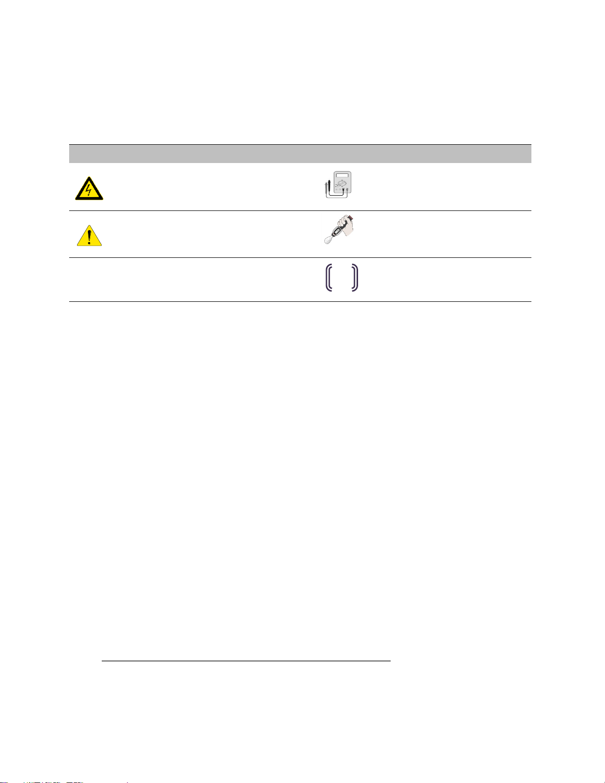
Symbol
Definition
Symbol
Definition
WARNING! A dangerous voltage or other
condition exists. Use extreme caution when
performing these tasks.
Meter measurement required.
CAUTION! This information is critical to the
safe installation and or operation of the inverter.
Follow these instructions closely.
Torque rating critical to operation.
NOTE: This statement is important. Follow
instructions closely.
Login to the remote monitoring system
for operating status
EMS
This manual contains important instructions for the Eguana Commercial AC Battery™ Energy Storage System. The
Eguana Commercial AC Battery™ components described by this manual are intended to be used as part of an Energy
Storage system and installed per all local building codes and regulations in addition to the National Electrical Code,
ANSI/NFPA 70 (for US) and Canadian Electrical Code (for Canada).
Throughout this manual, the following symbols will be used to highlight important information and procedures:
1.1 In case of emergency
In all cases:
If safe to do so, switch off the AC breakers (external to the system) .
Contact the fire department or other required emergency response team.
Evacuate the area, and if applicable, follow your emergency evacuation plan if others are in proximity to the
installed location.
In case of fire:
When safe, use a fire extinguisher suitable for use; including A, B, and C dry chemical fire extinguishers or
carbon dioxide extinguishers.
In case of flooding:
Stay out of water if any part of the system or wiring is submerged.
Do not attempt to operate batteries that have been submerged in water even after they have been dried.
In case of unusual noise, smell or smoke:
If safe to do so, ventilate the area.
1.2 Battery module safety precautions
This product is integrated with LG Chem EM048126P3S7 series battery modules. Refer to the LG Chem product
manual LG Chem P3S series 48V Standalone Battery Module Installation Manual, for complete safety instructions
regarding handling of battery modules.
1
1.3 General safety precautions
Risks of Fire
Do not expose the system to temperatures exceeding 60 degrees Celsius.
Avoid installation in direct sunlight.
Do not store objects on top of the cabinet.
Do not obstruct the airflow paths of the HVAC cooling system.
Do not obstruct the intake or exhaust of the forced airflow system.
Do not store combustible objects and corrosive chemicals directly adjacent to the system.
Risks of Shock
WARNING! Hazardous Voltages. The Inverter contains hazardous voltage and energy that may be lethal.
It may only be installed by qualified personnel who have read this manual and are familiar with its operation and
hazards.
Only connect the PCS cabinet to a compatible electrical service as defined in the model specifications. The PCS
must be connected to a dedicated branch circuit in the main electrical panel.
Ensure proper electrical grounding in accordance with code requirements.
CAUTION! Both AC and DC voltage sources are terminated inside this equipment. Each circuit must be
individually disconnected before servicing
Risks of Damage
The PCS is compatible with the LG Chem battery model EM048126P3S7 only. Do not attempt to connect any
other battery to the system.
Do not connect any other loads directly to the battery power bus.
Do not drop, tip, or puncture the cabinet during transport and installation. Visible damage to the cabinet
and/or internal components should be reported to the manufacturer immediately.
Do not store this system for periods longer than six months without a battery maintenance charge. This may
result in permanent damage to the batteries.
Important! Installation, service, and operating personnel must read this document in its entirety, and observe all
safety and installation procedures as described in this manual. Never operate system in a manner not described by
this manual.
Only qualified personnel should service this product.
Ensure all covers are securely fastened after installation is complete.
Personal Protective Equipment (PPE) in compliance with local work place safety standards must be worn when
working inside the cabinet.
1.4 Environmental Protection
Do not dispose of the system or any of the components within the cabinet. Batteries, electronics, cables, and metal
parts are recyclable. Consult your municipal waste management authority to determine required methods of
component recycling.
2

2 Introduction
Term
Definition
Term
Definition
AC
Alternating Current
NC
Normally Closed
ARC
Auto Recovery Circuit
NEC
National Electrical Code
CPU
Central Processing Unit
NO
Normally Open
DC
Direct Current
PCS
Power Control System (Inverter)
EMS
Energy Management System
PE
Protective Earth
ESD
Electrostatic Discharge
PV
Photo-Voltaic
ESS
Energy Storage System
RF
Radio Frequency
GND
Ground
SOC
State Of Charge (Battery)
LED
Light Emitting Diode
SOH
State of Health (Battery)
2.1 About this Manual – Target Audience
This manual is intended to be used by qualified service and installation personnel for the purposes of product
installation. This manual contains instructions for the installation and start up sequence of the Eguana Commercial AC
Battery energy storage system. This product is permanently wired to the electrical service, and must be installed by a
licensed electrician only.
This system requires an externally supplied energy management system to operate and manage the battery system.
The energy management system must be qualified and approved for use by Eguana Technologies to be compliant with
the manufacturer warranty. Consult the manufacturer for a list of approved energy management systems prior to
installation of this product.
2.2 Glossary
2.3 Initial Inspection of Material List
In addition to the battery system, the following additional components are supplied with your Eguana Commercial AC
Battery™ Energy Storage system. Each component should be inspected visually for any damage that may have been
caused by shipment. If damage is present, please contact your local distributor.
Cabinet canopy
Hardware kit
Installation and Startup Guide
Antenna (optional)
2.4 Installation materials not included
The following materials should be readily available to install the system:
CAT 5e communication cable of appropriate length and gauge (non-integrated EMS)
RJ-45 connectors (EMS communication)
Mounting hardware for pad mounting of cabinet – up to ½” hardware supported.
2.5 Special Tools
In addition to standard tools required for cabinet mounting, the following tools should be readily available to
interconnect the battery and PCS cabinets.
RJ-45 crimp tool (EMS to PCS communication cable).
3
3 Installation Site Preparation
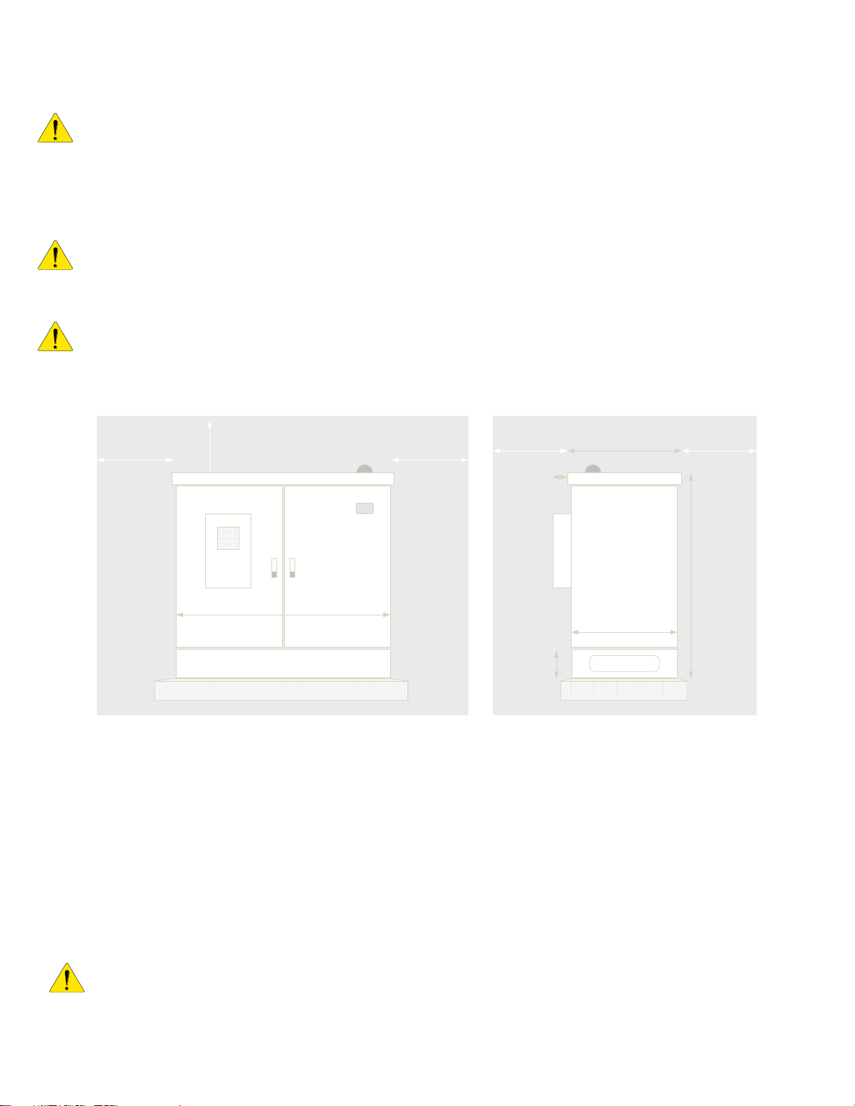
Figure 1: Mounting installation plan – minimum clearances required for installation and service access to the battery system.
1500 lbs
Clearance determined by boom lift
24"
6"
Front View
Canopy
Concrete pad
24"
PCS
Cabinet
Battery
Cabinet
Plinth
36"
Concrete pad
36"
Wiring port
Side (Right) View
31.9"
8"
53.75"
4"
47.6"
33.75"
Before installing the system, read all instructions and warnings in this manual.
CAUTION! All electrical and civil installation work should be performed in accordance with local building and
electrical codes.
3.1 Installation Planning
CAUTION! The cabinet weighs approximately 1500 lbs. Handle with care. All six lift points must be used to lift
the cabinet into its fixed position, and equal tension at all six lift points is required to prevent damage to the
interconnected cabinets. Ensure equipment and lift straps used are rated to safely install the system.
CAUTION! Avoid installation in direct sunlight. Battery performance is dependent upon operating ambient
temperature. Radiant heat absorbed in direct sunlight will greatly reduce the performance of the batteries and will
prematurely cause degradation of the display indicator panel on the front of the cabinet. The HVAC option will be
required where direct sunlight installation is the only option. Refer to Section 12 for more details.
3.2 Cabinet Plinth Pad-mount Dimensions
The following diagram illustrates the pad-mount footprint dimensions for the cabinet plinth, with relative position of the
field wiring ports near the front-right corner of the cabinet plinth. Anchoring of the cabinet is supported by four
mounting holes rated up to ½” (13 mm) anchor bolts.
CAUTION! Concrete pad or floor must be level to ensure proper weight distribution of rack-mount components
within the cabinet. All civil work should be performed in accordance with local building codes.
4
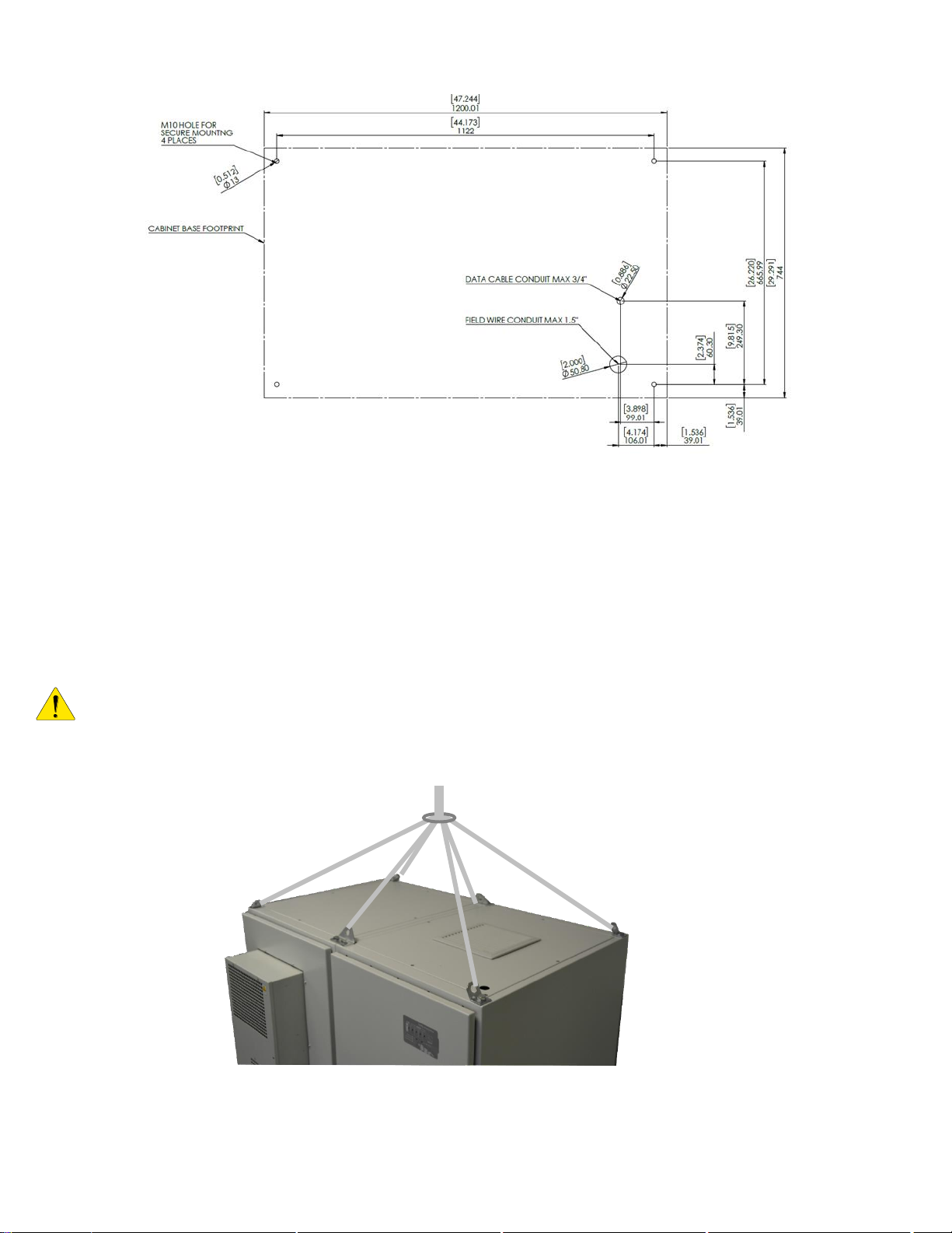
Figure 2: Cabinet Plinth Pad-mount dimensions.
front
3.3 Cabinet lift method
The following diagram illustrates the lift points. The two cabinets are interconnected at the base plinth and the top
center lift hardware. Note that the product is shipped without the canopy installed, such that it is ready for direct lift off
of the shipping pallet.
CAUTION! The cabinet weighs approximately 1500 lbs. Handle with care. All six lift points must be used to lift
the cabinet into its fixed position, and equal tension at all six lift points is required to prevent damage to the
interconnected cabinets. Ensure equipment and lift straps used are rated to safely install the system.
Figure 3: Lift points on the battery system.
5
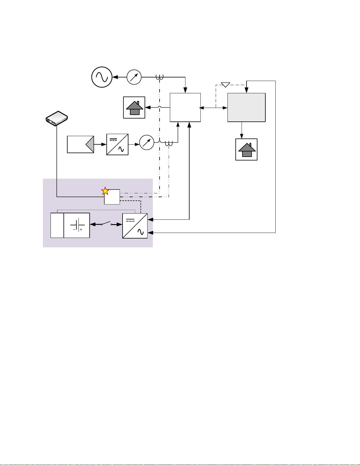
3.4 SLD - AC Coupled PV System with Back-up Power Operation
Eguana ACB15 ESS
Grid
BMS
PV Inverter
1
Main
Electrical
Panel
Sub-Panel
2
Critical loads
Loads
EMS
Loads
CAT-5
3
Grid
Load
ATS or Mechanical
Interlock
4
Home
network
The following block diagram is representative of an AC coupled solar plus storage system with backup power operation
(480V model only).
Important: The above diagram is a single line representation of a utility interactive battery system with AC coupled
PV to a critical load panel, based on the electrical ratings of the Eguana AC battery. Please consult your National and
local electrical codes for full compliance in an actual installation.
1 – PV Inverter should not exceed rating of base load plus battery inverter rating for optimal self-consumption and/or
where PV export to grid is not permitted.
2 – Sub-panel is grounded directly from the main panel.
3 – Refer to EMS/gateway specs for communication cabling requirements.
4 – An Automatic Transfer Relay (ATS) or Mechanical interlock is recommended in case of system service. This will
power critical loads directly from the grid.
Figure 4: Single Line Diagram: Typical AC coupled PV system.
6

4 Cabinet Installation Instructions
Figure 5: Wiring Port and Plinth mounting access.
Figure 6: Lowering canopy onto cabinet - antenna kit option
shown.
Figure 7: Fastening the canopy to the cabinet.
1. Lower the cabinet onto the concrete pad/floor, positioning
the cabinet over the mounting points. Remove the lift straps.
2. Secure the cabinet to the floor at the four corner mounting
points on the base of the plinth.
3. Lower the canopy cover onto the cabinets.
Note: Wi-Fi / Cellular antenna option; if your system was
delivered with an optional antenna kit, mount the antenna to
the canopy by adhering the gasket against the top of the
canopy and tightening the nut against the bottom side of the
canopy. Then lower the canopy onto the cabinets and route
the antenna cables through the cabinet port immediately
below the antenna. Propping the front of the canopy upward
towards the front will make cable routing easier.
4. Terminate the antenna cables at the EMS antenna inputs on
the inside of the PCS cabinet door. See the EMS installation
documentation for installation details.
5. Fasten the canopy to the cabinets using the 20 Phillips
screws and washers in the supplied hardware kit; 10 at the
front, and 10 at the rear of the cabinet.
7

5 Internal Product Layout
Ref
Definition
Ref
Definition
1
Air conditioner
9
Cabinet Plinth
2
Master Battery Module
10
Antenna
3
Battery Disconnect
11
AC Field Wiring Terminals
4
Canopy
12
EMS Control Panel (not included)
5
PCS Cabinet Exhaust Fan + Filter
13
Air Inlet + Filter
6
PCS Master – Phase A
14
(side) AC Wiring Port Access Panel
7
PCS Slave – Phase B
8
PCS Slave – Phase C
1
2
3 4 5 6 7 8 9
11
12
13
10
14
Figure 8: System Internal Layout.
8

6 System Electrical Wiring
Figure 10: PCS AC Grid and Load Wiring Terminals – 480 V
Wye model shown.
Figure 9: PCS AC Grid Wiring Terminals – 208 V Delta
model shown.
G
N
DL1 L2 L3
Grid
Note: This product is capable of providing utility interactive and islanded back up power and can be AC coupled to a
utility interactive photovoltaic inverter through the grid-coupled circuit. Wiring methods must be in accordance with
local electrical codes. The installer is responsible for ensuring that over-current protection is installed and sized
appropriately for the AC grid and off-grid output circuits, in accordance with the National Electrical Code, ANSI/NFPA
70, Canadian Electrical Code and local codes.
6.1 AC Grid and AC Load Wiring
CAUTION! To reduce the risk of fire, connect only to a dedicated circuit provided with appropriate branch circuit overcurrent protection in accordance with local electrical codes.
Refer to Figures 9 and 10 below for connection of AC Grid and AC load circuits. The AC wiring size for the AC grid
and AC Load is to be determined based on the AC over-current protection installed, and not to exceed ratings as
provided in table 2.
1. Route the AC Grid wiring (3 wire) from the main electrical panel to the [AC Grid] terminal block of the AC
Battery.
2. 480V model only: If applicable, route the AC Load wiring (3 wire) from the critical load panel to the [AC Load]
terminal block of the AC Battery.
WARNING! Improper connection of the wiring panel may result in equipment damage and cause personal
injury. Disconnect all AC and DC Sources prior to installation.
9

6.2 Chassis Grounding
EMS
PCS
PCS: RJ-45 Pin
G+shield G 3
A
A 4 B
B
5
EMS
Figure 11: EMS to PCS wiring.
1
In this section, “Chassis Ground” is referred to as “ground” or “grounding” unless otherwise mentioned.
The AC and DC grounding are intended to provide a low impedance signal path at all frequencies.
DC Ground Wiring Installation: The default setting for DC grounding is set for DC negative to ground. This is to indicate
that the DC negative terminal of the inverter is grounded within the PCS system.
AC Ground Wiring Installation: The AC power grounding is achieved through the ground terminal blocks which are
connected to the PE ground terminals on the AC Filter Boards If a neutral connection is present (ACB15-480), it is not
bonded to the AC power grounding within the unit. Refer to table 2 for wire ratings.
Note: The field ground wire rating applies to the AC circuit only. The DC source loop is internal to the battery
cabinet, and is rated accordingly.
Lightning Grounding: The inverter has built-in lightning protection. In order for the lightning protection to be effective,
the grounding for lightning currents must be provided via low impedance path from AC Filter Board to System Ground
and further to the building Ground/Earthing point.
6.3 EMS to PCS Communication Wiring & RJ45 Pin-out
The PCS provides the user with a communications link to an EMS controller via RS-485.
1. Connect the communication cable to the [EMS In] port (RJ-45) of the master PCS module (ref: fig 8, item 6).
Refer to the PCS pinout table below for terminating the PCS end. Refer to the EMS instruction manual for
communication wiring to the EMS. .
6.4 Auxiliary Actuator Relays
The AC Battery contains two actuators which can be used by the EMS to provide external alarm/control based on
different operating states or modes of service, referenced as shown (P10, P11 reference).
Refer to the EMS operator’s manual for implementation details.
10

7 Start-up Sequence
Battery Power Button Operation
Turn Batteries ON: Press and Release the
power button on the module designated as the
Master module (this is the top module within the
battery cabinet)
(PCS connected com cable).
Turn Batteries OFF: Press and hold 5
seconds the power button of any module
designated as a Slave Module. If all modules do
not shut off, repeat individually for each module.
Figure 12: Battery BMS interface.
CAUTION! Powering the energy storage system requires a specific start-up procedure. Please follow the
steps below.
CAUTION! If the battery disconnect has been placed in the OFF position at any time during operation, wait
one minute before returning to the ON position. Rapid cycling (less than one minute) of the battery
disconnect can cause damage to the pre-charge circuits of the PCS modules.
CAUTION! During the first start-up sequence after installation, the battery modules may require a battery
maintenance cycle to balance the SOC. This maintenance cycle requires a grid connection so that the PCS can be
commanded to charge the batteries. The PCS battery SOC alarm light will flash yellow if maintenance and/or other
battery faults are present. This procedure may take from a few minutes to a few hours, depending on the difference in
battery module SOC. Please refer to the PCS Service Manual for more information.
1. Remove the front cover from the battery cabinet adjacent to the
PCS cabinet.
2. Press the [Power] button (see above, label #8) on the master
battery module. The master battery module has communication
wired from the battery BMS port (label #3) to the PCS [BMS in]
port.
WARNING! When the batteries are turned ON, the battery voltage
will be present at the power panel assembly busbar where the
battery modules are terminated.
3. This step may take up to one minute.
Verify that the indicators are as shown in “Normal Operation” as shown below.
11

Figure 13: Battery breaker disconnect
turned ON.
EMS
Green indicator: The left indicator indicates normal operation.
Blue indicators (SOC): In normal operation, the four indicators on the right show the module’s state of charge (SOC).
Each indicator represents 25% of a full charge. If the SOC value is 50%, the three rightmost indicators are on solid
BLUE. The blue indicators of the slave modules look as below.
Whereas, the leftmost blue indicator on the master module flashes.
4. Also, verify that the module with the left-most flashing blue SOC indicator corresponds to the module which
has communication wired from the BMS to the PCS [BMS in] port.
Caution! If the battery module other than the module designated as a master has a flashing SOC light at startup, shut
down all battery modules by holding the [Power] button for 5 seconds. In this state, it may be necessary to shut down
battery modules individually. After all modules are OFF. Repeat steps 2 and 3.
5. Turn ON the Battery disconnect switch inside the battery cabinet (see Figure 13).
6. The PCS module will initialize, indicated by a brief flash of all
LEDs on the display panel, followed by a status of the battery
and PCS. Refer to table 5 for indicator status of the PCS.
7. Turn ON the AC breaker at the main electrical panel to the
PCS.
8 Operation
This product does not operate without a 3rd party supplied energy management system. Please consult the EMS
manual for operation of this system.
12

9 PCS Display Panel
Indicator
Status
Display mode
Display Color
Battery
Status
State of charge
(L-R): 5 LEDs, 20% SOC per LED
Green >20%, Yellow <20%
Initialized
One time blink
Multi
Charging
Flashing pattern - right
Green
Discharging
Flashing pattern - left
Green (Yellow <20%)
PCS
Status
Sleep/Standby
Blinking pattern
Green
Pre grid-connect notification
Flashing pattern
Blue
Grid connected
ON
Blue
Off-grid mode
ON or Blinking pattern
Green/Yellow
Service Status
Service
ON
Orange
Programming mode
ON
Green
Active sleep
Blinking pattern
Green
Pre-charge
Blinking pattern
Green
DC Ground Fault
Blinking pattern
Yellow
Auto-Recovery
All lights rapid blinking – See section 11 for more details.
Figure 14: PCS display panel.
Blink
Flash
Solid
ON
OFF
ON
OFF
ON
9.1 LED Display Indicators
The PCS cabinet is equipped with a display panel that provides
indication of the following:
Battery Operating State
PCS Operating State
(out of) Service Indicator
Refer to section 9.2 for a complete definition of indicator states.
To conserve energy, the LEDs will turn off after 5 minutes from
being activated. They can be re-activated by pressing the
service button.
9.2 PCS display panel indicator summary.
The LEDs on the PCS identify operating states by both display
mode and color.
The display mode patterns (shown right) are defined as:
Blink: short ON, long OFF
Flash: equal ON/OFF
Solid: steady ON
13

9.3 Service Button
PCS indicator status
Definition/Action
Service light ON
System is prevented from normal operation due to an internal fault. Upon first power up of the
system, the PCS can also go into service mode if the PCS is powered by the battery but there is no
valid AC source. Check the AC breaker for the ESS at the main panel. Log into the EMS via web
browser to retrieve the service code before attempting to clear the service code.
All panel lights flashing
The PCS has a valid AC power input, but does not detect a battery voltage, and the system is
attempting battery recovery. Check the battery disconnect. Check the communication cable from the
master battery module to the PCS’s BMS port (Appendix A – ref: A1). Notify service personnel if
this condition persists more than 30 minutes.
All panel lights OFF after service button
wake command
This indicates loss of both AC And DC sources to the PCS. Check AC and DC circuit breakers and
disconnects.
Sleep/standby mode engaged
This is a normal operating mode initiated by the EMS when the battery SOC reaches the maximum
or minimum SOC. Loss of EMS communication will also engage the PCS into sleep/standby mode.
If on initial power up of the system, the PCS does not exit sleep/ standby mode, and one to four
battery SOC lights are ON, inspect the EMS to PCS communication cable , and verify that the EMS
is powered.
Observed state
Action
Service button command
All panel lights off
Wake panel display
Press and release
Service light on
Exit service mode
Press and hold 5 seconds
The service button can be used to wake the LED display, and either place the system into or out of service mode, as
well as cycle through various operating modes. If the system has gone into service mode, the user can attempt to
bring the system back into normal operation using the service button. Note that on the Commercial AC Battery the
service button is only accessible from the inside of the PCS cabinet (on the LED circuit board, mounted on the door).
Refer to section 11 – Troubleshooting if the service button does not perform the action requested.
10 Maintenance
The energy storage system requires very little maintenance; annual inspections of the airflow path, and replacement of
the air intake and exhaust filters are all that is required. For models including the air conditioner, annual maintenance
is also required. Consult the Envicool manual included with the system for more details. There are two filters to
inspect and replace, if necessary (see- section 5, figure 8 for location of filters):
1. Exhaust fan filter – Inside the PCS cabinet, top-center.
2. Air inlet filter – Inside the front door of the PCS cabinet.
11 Troubleshooting
System faults are reported and logged in the monitoring system. All fault logs are also accessible remotely by your
installer.
IMPORTANT! Contact your system installer as recommended below if any of the following conditions are present on
the front display of the inverter panel.
14

12 Specifications
Model
ACB15
AC Grid Specifications
-208
-480
Nominal AC Voltage
208 V (L-L), 3 Phase Delta
480 V (L-L), 3 Phase Wye
AC Voltage Range (default)
-12% to +10% of nominal AC voltage
Nominal AC Frequency
60 Hz
Frequency Range (default)
59.3 to 60.5 Hz
Rated AC Current
41.6 A (Line)
18.1 A (Line)
Continuous AC Power
15000 VA
Power Factor
> 0.99 (fixed) / 0.8 leading to 0.8 lagging (adjustable)
Harmonic Distortion
< 5%
Efficiency (PCS only)
96% Peak
Maximum Output Overcurrent Protection
60 A
Maximum AC Short-circuit Current
99 A
pk-pk
, 2.1 A
rms
(50 ms)
Maximum Synchronization In-rush Current
32 A
pk-pk
, 2.0 A
rms
(50 ms)
Galvanic Isolation
Integrated transformer
Protective Class (I, II, or III)
Class I
Over-Voltage Category (OVC I, II, III, or IV)
OVC III
Pollution Degree
3
Lightning Protection
IEEE 62.41.2, location category C, low exposure
Active Anti-islanding Method
Sandia frequency shift
Grid Monitoring
Active in all states
Configurable Grid Management Functions
Watt Reduction, VAR Control, VRT/FRT Control
Power Ramp Rate
0.1% to 100% / sec, programmable
Energy Storage Specifications
-39
Rated AC Energy
39.1 kWh
Rated Charge / Discharge Current
300 Adc / 375 Adc
Nominal DC Voltage
48 Vdc
Operating DC Range
40 to 65 Vdc
DC Overcurrent Protection
525 Adc
Mechanical
Base Model
-H (HVAC option)
Max Humidity
< 95% (non-condensing)
Enclosure Type
Type 3R outdoor
Cooling - PCS Cabinet
Fans
Fans
Cooling - Battery Cabinet
Natural convection
Air conditioned
Enclosure Dimensions (WxHxD)
1245 x 1365 x 857 mm
1245 x 1365 x 959 mm
(excluding antenna)
49" x 53.75" x 33.75"
49" x 53.75" x 37.75"
Antenna Height
82 mm
3.2”
Enclosure Weight
653 kg
1437 lbs
674 kg
1483 lbs
Operating Temperature
-10 to +45 C
-15 to +50 C
Full Load Operating Temperature
0 to +40 C
-5 to +45 C
Air Conditioner, Base Load Power
-
300 Watt
General Specifications
External Communication
Modbus RTU (RS-485)
Display
LED indication
Self-consumption Power (without HVAC)
< 300 W (operating), 15 W (sleep)
Ground Fault Monitoring
DC grounded system configuration
Auxiliary Dry Contacts (programmable, x2)
240V, 10A rated
Table 1: PCS Electrical / Mechanical Ratings
15

Standards & Certifications
EMC
FCC, part 15-B
Utility Interface and Safety
UL1741 SA, IEEE 1547, CSA C22.2 No. 107.1
Battery System Safety
UL 9540, UL1973
AC Voltage / Frequency Trip Limits: UL1741 (IEEE 1547.1)
Model
-208
-480
Low Volt Trip (adj), AC voltage
Default
183.0 V (L-L)
243.8 V (L-N)
Min/Max
104.0 - 183.0 V (L-L)
138.5 - 243.8 V (L-N)
Low Volt Trip Time (adj.)
Default
117 cycles (1.95 sec)
Min/Max
0 - 3600 cycles (60.0 sec)
High Volt Trip (adj.), AC voltage
Default
228.8 V (L-L)
304.7 V (L-N)
Min/Max
228.8 - 249.6 V (L-L)
304.7 - 332.4 V (L-N)
High Volt Trip Time (adj.),
Default
57 cycles (0.95 sec)
Min/Max
0 - 3600 cycles (60.0 sec)
Undervoltage: (Very Low) Trip Limit, AC voltage
< 104.0 V (L-L)
< 138.5 V (L-N)
Undervoltage: (Very Low) Trip Time
< 10 cycles (0.16 sec)
Overvoltage: (Very High) Trip Limit, AC voltage
> 249.6 V (L-L)
332.4 V (L-N)
Overvoltage: (Very High) Trip Time
< 10 cycles (0.16 sec)
Underfrequency Trip (adj), frequency
Default
59.3 Hz
Min/Max
55.0 - 59.3 Hz
Underfrequency Trip Time (adj)
Default
< 10 cycles (0.16 sec)
Min/Max
0 - 3600 cycles (60.0 sec)
Overfrequency Trip (adj), frequency
Default
60.5 Hz
Min/Max
60.5 - 65.0 Hz
Overfrequency Trip Time (adj)
Default
< 10 cycles (0.16 sec)
Min/Max
0 - 3600 cycles (60.0 sec)
Frequency Trip Limit Accuracy
0.01 Hz
Frequency Trip Time Accuracy
0.05 sec
AC Voltage Trip Limit Accuracy
1% of nominal
AC Voltage Trip Time Accuracy
0.05 sec
Field Wiring
Use Copper Wire Only, 90°C or higher rated
Terminal
Minimum Wire Size mm2
(AWG)
Maximum Wire Size mm2
(AWG)
Tightening Torque, Nm (in.
lbs)
Ground Lug
16 mm2 (6 AWG)
16 mm2 (6 AWG)
1.7 (15.0)
AC Grid Terminals*
6 mm2 (10 AWG)
16 mm2 (6 AWG)
1.7 (15.0)
AC Load Terminals*
6 mm2 (10 AWG)
16 mm2 (6 AWG)
1.7 (15.0)
Table 2: PCS Field Wiring Ratings – AWG / Torque
*Note: See rated AC current in table 1 for nominal phase currents. Wire ratings are based on product terminal ratings.
16

12.1 UL 1741 SA Grid Support Utility Interactive Inverter Specifications
Grid Support Function Tested
Test Standard
Anti-Islanding protection – unintentional islanding with grid support functions enabled
UL 1741 SA 8
Low/high voltage ride through
UL 1741 SA 9
Low/high frequency ride through
UL 1741 SA 10
Ramp rates
UL 1741 SA 11
Reconnect by “Soft Start”
UL 1741 SA 11
Specified power factor
UL 1741 SA 12
Dynamic Volt/VAR operations
UL 1741 SA 13
Frequency-Watt
UL 1741 SA 14
Volt-Watt
UL 1741 SA 15
SA9 Low and High Voltage Ride Through - Rule 21
Region
Voltage Range
[%Vnom]
Ride
Through
Duration [s]
Maximum
Trip Time [s]
Operating Mode During Ride
Through
High Voltage 2 (HV2)
V > 120%
N/A
0.16
N/A
High Voltage 1 (HV1)
110% < V ≤ 120%
12
13
Momentary Cessation (zero power)
Near Nominal (NN)
88% ≤ V ≤ 110%
Indefinite
N/A
Continuous Operation
Low Voltage 1 (LV1)
70% ≤ V < 88%
20
21
Mandatory Operation
Low Voltage 2 (LV2)
50% ≤ V < 70%
10
11
Mandatory Operation
Low Voltage 3 (LV3)
V < 50%
1
1.5
Momentary Cessation (zero power)
SA9 Low and High Voltage Ride Through - Rule 14H
Region
Voltage Range
[%Vnom]
Ride
Through
Duration [s]
Maximum
Trip Time [s]
Operating Mode During Ride
Through
Over Voltage 2 (OV2)
V > 120%
N/A
0.16
Cease to Energize
Over Voltage 1 (OV1)
110% < V ≤ 120%
0.92 1 Mandatory Operation (VW)
Continuous Operation
(CO)
88% ≤ V ≤ 110%
N/A
N/A
Continuous Operation (VW)
Under Voltage 1 (UV1)
70% ≤ V < 88%
20
21
Mandatory Operation
Under Voltage 2 (UV2)
50% ≤ V < 70%
10
11
Mandatory Operation
Under Voltage 3 (UV3)
V < 50%
1
1.5
Momentary Cessation (zero power)
Parameter
Abbreviation
Value for Rule 21
Value for Rule 14H
Nominal AC voltage [V]
Vnom
208 or 277
AC voltage accuracy [%Vnom or V]
MSA-vac
1%
Voltage trip time accuracy [s]
MSA-ttv
0.05
Voltage range of adjustability [%Vnom]
Vvrtmin-Vvrtmax
0.0% - 120.0%
Trip time range of adjustability [s]
Tvrtmin-Tvrtmax
0.0 - 50.0
Default function status
Enabled
Enabled
The PCS within the Commercial AC Battery complies with the UL 1741SA standard for grid support utility interactive
inverters. These functions are intended to be either enabled or disabled in accordance with local utility interconnection
requirements. The UL 1741 SA testing was conducted in accordance with both Rule 21 and Rule 14H (V1.1) as
source requirements documents (SRD), which are applicable in jurisdictions within California and Hawaii, respectively.
The corresponding default settings and specifications are listed below.
Table 3: UL1741 SA grid support functions.
Table 4: Low and high voltage ride through settings.
17

Table 5: Low and high frequency ride through settings.
SA10 Low and High Frequency Ride Through - Rule 21
Region
Frequency
Range [Hz]
Ride
Through
Duration [s]
Maximum
Trip Time [s]
Operating Mode During Ride
Through
High Frequency 2 (HF2)
f > 62.0
N/A
0.16
N/A
High Frequency 1 (HF1)
60.5 < f ≤ 62.0
299
300
Mandatory Operation (FW)
Near Nominal (NN)
58.5 ≤ f ≤ 60.5
Indefinite
Indefinite
Continuous Operation
Low Frequency 1 (LF1)
57.0 ≤ f < 58.5
299
300
Mandatory Operation
Low Frequency 2 (LF2)
f < 57.0
N/A
0.16
N/A
SA10 Low and High Frequency Ride Through - Rule 14H: Oaho, Maui, Hawaii
Region
Frequency
Range [Hz]
Ride
Through
Duration [s]
Maximum
Trip Time [s]
Operating Mode During Ride
Through
Over Frequency 2 (OF2)
f > 64.0
N/A
0.16
N/A
Over Frequency 1 (OF1)
63.0 < f ≤ 64.0
20
21
Mandatory Operation (FW)
Continuous Operation
(CO)
57.0 ≤ f ≤ 63.0
Indefinite
Indefinite
Continuous Operation (FW)
Under Frequency 1 (UF1)
56.0 ≤ f < 57.0
20
21
Mandatory Operation
Under Frequency 2 (UF2)
f < 56.0
N/A
0.16
N/A
SA10 Low and High Frequency Ride Through - Rule 14H: Lanai, Molokai
Region
Frequency
Range [Hz]
Ride
Through
Duration [s]
Maximum
Trip Time [s]
Operating Mode During Ride
Through
Over Frequency 2 (OF2)
f > 65.0
N/A
0.16
N/A
Over Frequency 1 (OF1)
63.0 < f ≤ 65.0
20
21
Mandatory Operation (FW)
Continuous Operation
(CO)
57.0 ≤ f ≤ 63.0
Indefinite
Indefinite
Continuous Operation (FW)
Under Frequency 1 (UF1)
50.0 ≤ f < 57.0
20
21
Mandatory Operation
Under Frequency 2 (UF2)
f < 50.0
N/A
0.16
N/A
Parameter
Abbreviation
Value for Rule 21
Value for Rule 14H
Nominal frequency [V]
fnom
60
AC frequency measurement accuracy [Hz]
MSA-f
0.02
Frequency trip time accuracy [s]
MSA-ttf
0.05
Frequency range of adjustability [Hz]
ffrtmin-ffrtmax
50.0 - 66.0
Trip time range of adjustability [s]
Tfrtmin-Tfrtmax
0.0 - 1000.0
Default function status
Enabled
Enabled
18

Table 6: Ramp rate settings.
SA11 Ramp Rates
Parameter
Abbreviation
Value for Rule 21
Value for Rule 14H
Output current rating [A]
Irated
41.6 A (208 V Delta), 18.1 A (480 V Wye)
Minimum normal ramp up rate [%Irated/sec]
RRnorm_min
1.0%
Maximum normal ramp up rate
[%Irated/sec]
RRnorm_max
100.0%
Minimum output current [A]
Ilow
0
Ramp Rate Accuracy [%Irated/sec]
MSA-rr
N/A
Minimum soft start ramp up rate
[%Irated/sec]
RRss_min
0.1%
Maximum soft start ramp up rate
[%Irated/sec]
RRss_max
100.0%
Default normal ramp up rate [%Irated/sec]
RRnorm
100.0%
100.0%
Default soft start ramp function status
Enabled
Enabled
Default soft start ramp up rate [%Irated/sec]
RRss
2.0%
0.33%
SA12 Specified Power Factor
Parameter
Abbreviation
Value for Rule 21
Value for Rule 14H
Apparent power rating [VA]
Srated
15000
Output power rating [W]
Prated
15000
DC input voltage range with function
enabled [V]
Vdcmin-Vdcmax
40.0 - 80.0
Nominal AC voltage [V]
Vnom
208 (L-L, Delta) or 277 (L-N, Wye)
AC voltage range with function enabled
[%Vnom]
Vmin-Vmax
88.0% - 110.0%
AC voltage accuracy [%Vnom or V]
MSA-vac
1%
DC voltage measurement accuracy [V]
MSA-vdc
0.05
Active power range of function [W]
Plow, Prated
3000 - 15000
750 - 15000
Power Factor Accuracy
MSA-pf
0.01
Power Factor settling time [sec]
Ts-pf
5
Minimum inductive power factor
PF min,ind
-0.8
Minimum capacitive power factor
PF min,cap
0.8
Mid inductive power factor
PF mid,ind
-0.9
Mid capacitive power factor
PF mid,cap
0.9
Default function status
Disabled
Disabled
Power factor default
PF
-0.95
-0.95
SA13 Volt-VAr Mode
Parameter
Abbreviation
Value for Rule 21
Value for Rule 14H
Apparent power rating [VA]
Srated
15000
Output power rating [W]
Prated
15000
EUT input voltage range with function
enabled [V]
Vdcmin-Vdcmax
40.0 - 80.0
Nominal AC EPS voltage [V]
Vnom
208 (L-L, Delta) or 277 (L-N, Wye)
Table 7: Specified power factor settings.
Table 8: Volt- VAr settings.
19

AC EPS voltage range with function
enabled [V]
Vmin-Vmax
96.0 - 144.0
Reactive power accuracy [%Srated, VAr]
MSA-q
5%, 250VAr
Maximum ramp rate [VAr/s]
RRvar
500
Maximum rated reactive power production
(capacitive, overexcited) [VAr]
Qmax,cap
6600
Maximum rated reactive power production
(inducitive. underexcited) [VAr]
Qmax,ind
-6600
Minimum rated reactive power production
(capacitive, overexcited) [VAr]
Qmin,cap
750
Minimum rated reactive power production
(inducitive. underexcited) [VAr]
Qmin,ind
-750
Maximum slope [VAr/V]
KVARmax
1587
Deadband range [%Vnom]
Deadmand_min
0.0 - 20.0
Deadband_max
Time accuracy [s], related Tr-vv
MSA-t
2
Settling time [s]
Ts-vv
3
Default function status
Enabled
Enabled
Default response time, ramp to Qmax,ind
[s]
Tr-vv
10
10
Default power prioritization
P/Q Priority Q Q
Default Voltage at Q1 [%Vnom]
V1
94.3%
94.0%
Default max reactive power production
setting [VAr]
Q1
4500
6600
Default voltage at Q2 [%Vnom]
V2
98.0%
97.0%
Default reactive power setting at lower
voltage deadband limit [VAr]
Q2
0
0
Default voltage at Q3 [%Vnom]
V3
102.0%
103.0%
Default reactive power setting at upper
voltage deadband limit [VAr]
Q3
0
0
Default voltage at Q4 [%Vnom]
V4
105.7%
106.0%
Default max reactive power absorption
setting [VAr]
Q4
-4500
-6600
SA14 Frequency Watt
Parameter
Abbreviation
Value for Rule 21
Value for Rule 14H
Output Power Rating [W]
Prated
15000
AC frequency range with function enabled
[Hz]
fmin, fmax
60.0 - 65.0
AC frequency measurement accuracy [Hz]
MSA-f
0.02
P(f) accuracy [%Prated or W]
MSA-p(f)
2%, 300W
Settling time [sec]
Ts-fw
3
Adjustment range of response time [s]
Tr-fw
0.5 - 3.0
* Volt-VAr mode can function with active or reactive power priority. When an inverter is set in Volt-VAr mode with
reactive power priority and the inverter's apparent power kVA limit is reached, active power is reduced to maintain
reactive power production. When an inverter is set in Volt-VAr mode with active power priority and the inverter's
apparent power kVA limit is reached, the reactive power is reduced to maximize active power production.
Table 9: Frequency-watt Settings
20

Adjustment range of the start of frequency
droop [Hz]
fstart_min,
fstart_max
60.017 - 63.0
Maximum slope of frequency droop
[%Prated/Hz]
Kpower-freq_max
100.0%
Minimum slope of frequency droop
[%Prated/Hz]
Kpower-freq_min
23.8%
Default function status
Enabled
Enabled
Default response time, ramp to 10% Prated
[s]
Tr-fw
0.5
0.5
Default start frequency [Hz]
fstart
60.1
60.036
Default slope of frequency droop
[%Prated/Hz]
Kpower-freq
50.0%
41.7%
Default use of hysteresis (symmetric
recovery)
Enabled
Enabled
SA15 Voltage Watt
Parameter
Abbreviation
Value for Rule 21
Value for Rule 14H
Output power rating [W]
Prated
15000
AC voltage range with function enabled
[%Vnom]
Vmin-Vmax
1.00 - 1.12
Nominal AC voltage [V]
Vnom
208 (L-L, Delta) or 277 (L-N, Wye)
AC voltage accuracy [%Vnom or V]
MSA-vac
1%
Output power accuracy [%Prated or W]
MSA-watts
2%, 300W
Time accuracy [s], related to treturn_min,
treturn_max, Tr-vw
MSA-t
2
Setting time [sec]
Ts-vw
3
Adjustment range of the start of active
power reduction [%Vnom]
Vstart_min,
Vstart_max
102.0% - 106.0%
Adjustment range of the stop of the
curtailment function [V]
Vstop_min.,Vstop_
max
101.0% - 105.0%
Maximum Slope of active power reduction
[%Prated/V]
Kpower-volt_max
36.1%
Minimum slope of active power reduction
[%Prated/V]
Kpower-volt_min
4.5%
Range of adjustment of a delay before
return to normal operation [sec]
treturn_min,
treturn_max
1.0 - 60.0
Adjustment range of the rate of return to
normal operation [%Prated/sec]
Kpower_rate_min.
Kpower_rate_max
10.0 - 100.0%
Default function status
Disabled
Disabled
Power duration reference
Pre-disturbance
Rated
Default response time, ramp to 10% Prated
[s]
Tr-vw 1 10
Default start voltage [%Vnom]
Vstart
106.0%
106.0%
Default stop voltage [%Vnom]
Vstop
105.0%
106.0%
Default active power slope [%Prated/V]
Kpower_volt
20.8%
20.8%
Default use of hysteresis (symmetric
recovery)
Disabled
Enabled
Default delay before return to normal
operation [s]
treturn 1 N/A
Default active power rate of return to normal
operation [%Prated/s]
Kpower_rate
100
N/A
Table 10: Voltage-watt Settings
21

12.2 Thermal Performance of PCS and Battery Modules
0
2000
4000
6000
8000
10000
12000
14000
16000
0 10 20 30 40 50 60 70 80 90 100
AC POWER (VA)
SOC (%)
Commercial AC Battery
AC Power Charge Derating
Charge (VA)
50
15 to 45°C
10°C
-10°C
50°C
The following charts indicate the power performance of the PCS and batteries based on the outside ambient operating
temperature. Note that direct sunlight can significantly raise the internal temperature of the batteries. Avoiding
installation in direct sunlight is critical to the long term performance and operation of the battery.
22

0
2000
4000
6000
8000
10000
12000
14000
16000
0 10 20 30 40 50 60 70 80 90 100
AC POWER (VA)
SOC (%)
Commercial AC Battery
AC Discharge Power Derating
Discharge (VA)
50
5°C
0°C
-5°C
-10°C
15°-45C
50°C
Figure 15: Thermal operating range of PCS and Battery.
23

Appendix A: ACB-15 Series Electrical Block Diagrams
Battery Cabinet
PCS Cabinet
Battery 1
DC+ Busbar
Circuit Breaker
DIN mount
ABB S201-C3
Bidirex, L3
Bidirex, L2
L1
Bidirex, L1 master
G
3-pole breaker
175A / pole
80V
ABB ATA175TW
Cellular
Antenna
N
Battery 2
Battery 3
Battery 4
Battery 5
Battery 6
DC+, DC- Cables
6 AWG
DC Feeder Cables
THHW, 2/0
300V
90C min
1323 x 30
DC+/DC-: Red/Black
L
AC Line/Load Cables
6 AWG
L1/L2/L3/N/G:
Heat shrink color labels
Feed-through
Terminal Blocks
DIN mount
ABB ZS16 (-PE)
Feed-through
Terminal Blocks
DIN mount
ABB ZS4 (-PE)
AC Aux Cables
14 AWG
Red/White/Green
DC- Busbar
N
G
AC
Grid
AC
Load
L
N
G
L
N
L
N
G
L
N
L
N
G
L
N
AC
Grid
AC
Load
AC
Grid
AC
Load
DC+
DC-
DC+
DC-
DC+
DC-
Grid Main
Panel
L2
L3
L
N
N
AK1
N/O
AK2
N/O
AK1 AK2
AK1 AK2
G
G
G
PE
PE
PE
PE
PE
Cabinet/cabinet
ground continuity
DC- PE cable
THHW, 2/0
300V
90C min
1323 x 30
Terminated to chassis
L1
N
L2
L3
N
Aux Load Circuit
230Vac
Max 3A
Int
Load
L
N
N
Energy Management System
Max 30W
L3
AC Backup (optional)
AC Grid
Exhaust Fan
Max 80W
L
L
Backup
Load Panel
Heating/Air Conditioning Unit
Max 500W
A.1: Three Phase 480 V Wye
24

A.2: Three Phase 208 V Delta
Battery Cabinet
PCS Cabinet
Battery 1
DC+ Busbar
Circuit Breaker
DIN mount
ABB S201-C3
Bidirex, L3
Bidirex, L2
L1
Bidirex, L1 master
G
3-pole breaker
175A / pole
80V
ABB ATA175TW
Cellular
Antenna
L1
Battery 2
Battery 3
Battery 4
Battery 5
Battery 6
DC+, DC- Cables
6 AWG
DC Feeder Cables
THHW, 2/0
300V
90C min
1323 x 30
DC+/DC-: Red/Black
AC Line/Load Cables
6 AWG
L1/L2/L3/N/G:
Heat shrink color labels
Feed-through
Terminal Blocks
DIN mount
ABB ZS16 (-PE)
Feed-through
Terminal Blocks
DIN mount
ABB ZS4 (-PE)
AC Aux Cables
14 AWG
Red/White/Green
DC- Busbar
L2
L3
G
AC
Grid
AC
Load
L
N
G
L
N
L
N
G
L
N
L
N
G
L
N
AC
Grid
AC
Load
AC
Grid
AC
Load
DC+
DC-
DC+
DC-
DC+
DC-
Grid Main
Panel
L2
L3
N
N
AK1
N/O
AK2
N/O
AK1 AK2
AK1 AK2
G
G
G
PE
PE
PE
PE
PE
Cabinet/cabinet
ground continuity
DC- PE cable
THHW, 2/0
300V
90C min
1323 x 30
Terminated to chassis
Aux Load Circuit
230Vac
Max 3A
L
Int
Load
L
N
AC Grid
Energy Management System
Max 30W
Exhaust Fan
Max 80W
L
Heating/Air Conditioning Unit
Max 500W
L
L
25

A.3 Communication
Battery 5
Battery 1
Bidirex, L3
Bidirex, L2
PCS Cabinet
Cellular
Antenna
Battery 2
Battery 3
Battery 4
Battery 6
Ext
Int
Int
Ext
Int
Int
Ext
Int
Int
Ext
Int
Int
Ext
Int
Int
Bidirex, L1 master
Comm 1
Comm 1
Comm 1
Comm 2
sync
Comm 2
sync
Comm 2
sync
Energy Management System
Heating/Air Conditioning Unit
Ext
Int
Int
Battery Cabinet
BMS
Exhaust Fan
AUX1
AUX2
BMS
BMS
CAN bus
Modbus
Proprietary
Protocol
Relay
control
Relay
control
Modbus
26

THIS PAGE INTENTIONALLY LEFT BLANK
27
 Loading...