

EGQ GC162035 User Manual
TEST REPORT
FCC ID: 2AMXLGC162035
Product: TPMS
Model No.: FI87
Additional Model: FE87
Trade Mark: EGQ
Report No.: TCT170704E020
Issued Date: Jul. 11, 2017
Issued for:
Shenzhen EGQ cloud technology Co., LTD
1st Floor, Building B, No.2, Minying Road, The 3rd industrial area of
Shilongzai, Shiyan Street, Baoan, Shenzhen, China
Issued By:
Shenzhen TCT Testing Technology Co., Ltd.
1B/F., Building 1, Yibaolai Industrial Park, Qiaotou, Fuyong, Baoan District,
Shenzhen, Guangdong, China
TEL: +86-755-27673339
FAX: +86-755-27673332
Note:
This report shall not be reproduced except in full, without the written approval of Shenzhen Tongce Testing Lab.
This document may be altered or revised by Shenzhen Tongce Testing Lab. personnel only, and shall be noted in
the revision section of the document. The test results in the report only apply to the tested sample.
Hotline: 400-6611-140 Tel: 86-755-27673339 Fax: 86-755-27673332 http://www.tct-lab.com
Report No.: TCT170704E020
TABLE OF CONTENTS
1. Test Certification....................................................................................... 3
2. Test Result Summary ............................................................................... 4
3. EUT Description ........................................................................................ 5
4. Genera Information ................................................................................... 6
4.1. Test Environment and Mode ............................................................................................................ 6
4.2. Description of Support Units ........................................................................................................... 6
5. Facilities and Accreditations ................................................................... 7
5.1. Facilities ............................................................................................................................................. 7
5.2. Location ............................................................................................................................................. 7
5.3. Measurement Uncertainty ................................................................................................................ 7
6. Test Results and Measurement Data ...................................................... 8
6.1. Antenna Requirement ....................................................................................................................... 8
6.2. Conducted Emission ......................................................................................................................... 9
6.3. Radiated Emission Measurement .................................................................................................. 10
6.4. Occupied Bandwidth ....................................................................................................................... 18
6.5. Transmission time and silent time ................................................................................................ 20
Appendix A: Photographs of Test Setup
Appendix B: Photographs of EUT
Hotline: 400-6611-140 Tel: 86-755-27673339 Fax: 86-755-27673332 http://www.tct-lab.com
Page 2 of 28
Report No.: TCT170704E020
1. Test Certification
Product:
Model No.:
Additional
Model No.:
Trade Mark:
Applicant:
Address:
Manufacturer:
Address:
Date of Test:
Applicable
Standards:
TPMS
FI87
FE87
EGQ
Shenzhen EGQ cloud technology Co., LTD
1st Floor, Building B, No.2, Minying Road, The 3rd industrial area of
Shilongzai, Shiyan Street, Baoan, Shenzhen, China
Shenzhen EGQ cloud technology Co., LTD
1st Floor, Building B, No.2, Minying Road, The 3rd industrial area of
Shilongzai, Shiyan Street, Baoan, Shenzhen, China
Jul. 05 –Jul. 10, 2017
FCC CFR Title 47 Part 15 Subpart C Section 15.231
The above equipment has been tested by Shenzhen Tongce Testing Lab. and found
compliance with the requirements set forth in the technical standards mentioned above. The
results of testing in this report apply only to the product/system, which was tested. Other
similar equipment will not necessarily produce the same results due to production tolerance
and measurement uncertaintie
Tested By: Date: Jul. 10, 2017
Reviewed By: Date: Jul. 11, 2017
Joe Zhou
Approved By: Date: Jul. 11, 2017
Tomsin
Hotline: 400-6611-140 Tel: 86-755-27673339 Fax: 86-755-27673332 http://www.tct-lab.com
Jin Wang
Page 3 of 28
Report No.: TCT170704E020
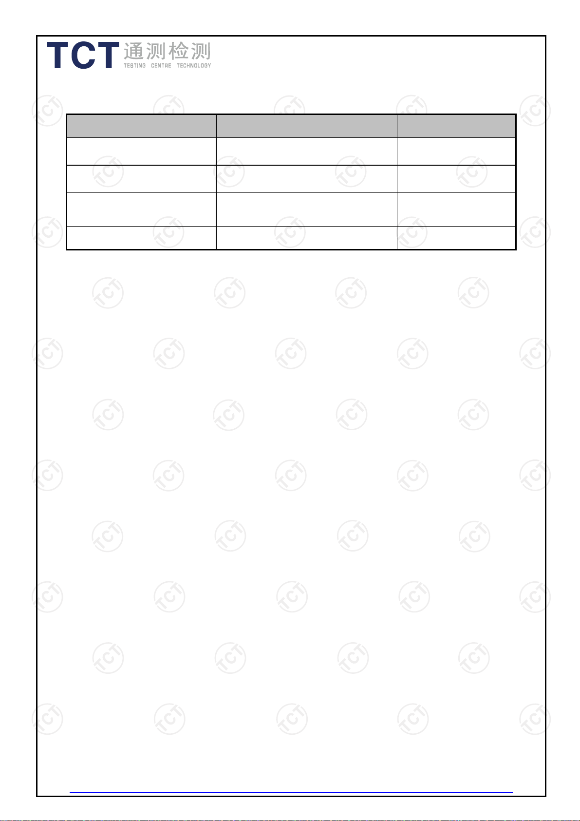
2. Test Result Summary
Requirement CFR 47 Section Result
Conduction Emission,
0.15MHz to 30MHz
Manually Activated
Transmitter
Radiation Emission §15.231(b), §15.205, §15.209,
Occupied Bandwidth
Note:
1. PASS: Test item meets the requiremen t.
2. Fail: Test item does not meet the requi remen t.
3. N/A: Test case does not apply to the test object.
4. The test result judgment is de cided by the limi t of te st st anda rd.
§15.207 N/A
§15.231(a) PASS
§15.35
PASS
§15.231(c) PASS
Hotline: 400-6611-140 Tel: 86-755-27673339 Fax: 86-755-27673332 http://www.tct-lab.com
Page 4 of 28
Report No.: TCT170704E020
3. EUT Description
Product Name:
Model :
Additional Model:
Trade Mark:
Operation Frequency:
Modulation Technology:
Antenna Type:
Antenna Gain:
Power Supply:
Remark:
TPMS
FI87
FE87
EGQ
433.92MHz
FSK
External Antenna
0dBi
DC 3V( The button battery*1)
All models above are identical in interior structure,
electrical circuits and components, just model names and
trademark are different for the marketing requirement.
Hotline: 400-6611-140 Tel: 86-755-27673339 Fax: 86-755-27673332 http://www.tct-lab.com
Page 5 of 28
Report No.: TCT170704E020
4. Genera Information
4.1. Test Environment and Mode
Operating Environment:
Temperature:
24.0 °C
Humidity: 54 % RH
Atmospheric Pressure: 1010 mbar
Test Mode:
Operation mode: Keep the EUT in continuous transmitting
with modulation
The sample was placed (0.8m below 1GHz, 1.5m above 1GHz) above the ground
plane of 3m chamber. Measurements in both horizontal and vertical polarities were
performed. During the test, each emission was maximized by: having the EUT
continuously working, investigated all operating modes, rotated about all 3 axis (X, Y &
Z) and considered typical configuration to obtain worst position, manipulating
interconnecting cables, rotating the turntable, varying antenna height from 1m to 4m in
both horizontal and vertical polarizations. The emissions worst-case are shown in Test
Results of the following pages.
4.2. Description of Support Units
The EUT has been tested as an independent unit together with other necessary
accessories or support units. The following support units or accessories were used to
form a representative test configuration during the tests.
Equipment Model No. Serial No. FCC ID Trade Name
/ / / / /
Note:
1. All the equipment/cables were placed in the worst-case configuration to maximize the emission during the test.
2. Grounding was established in accordance with the manufacturer’s requirements and conditions for the intended
use.
Hotline: 400-6611-140 Tel: 86-755-27673339 Fax: 86-755-27673332 http://www.tct-lab.com
Page 6 of 28
Report No.: TCT170704E020
5. Facilities and Accreditations
5.1. Facilities
The test facility is recognized, certified, or accredited by the following organizations:
● FCC - Registration No.: 572331
Shenzhen Tongce Testing Lab
The 3m Semi-anechoic chamber has been registered and fully described in a report
with the (FCC) Federal Communications Commission. The acceptance letter from the
FCC is maintained in our files.
● IC - Registration No.: 10668A-1
The 3m Semi-anechoic chamber of Shenzhen TCT Testing Technology Co., Ltd. has
been registered by Certification and Engineering Bureau of Industry Canada for radio
equipment testing
5.2. Location
Shenzhen Tongce Testing Lab
Address: 1B/F., Building 1, Yibaolai Industrial Park, Qiaotou, Fuyong, Baoan District,
Shenzhen, Guangdong, China
TEL: +86-755-27673339
5.3. Measurement Uncertainty
The reported uncertainty of measurement y ± U, where expended uncertainty U is based
on a standard uncertainty multiplied by a coverage factor of k=2, providing a level of
confidence of approximately 95 %.
No. Item MU
1 Conducted Emission ±2.56dB
2 RF power, conducted ±0.12dB
3 Spurious emissions, conducted ±0.11dB
4 All emissions, radiated(<1G) ±3.92dB
5 All emissions, radiated(>1G) ±4.28dB
6 Temperature ±0.1°C
7 Humidity ±1.0%
Hotline: 400-6611-140 Tel: 86-755-27673339 Fax: 86-755-27673332 http://www.tct-lab.com
Page 7 of 28
Report No.: TCT170704E020
6. Test Results and Measurement Data
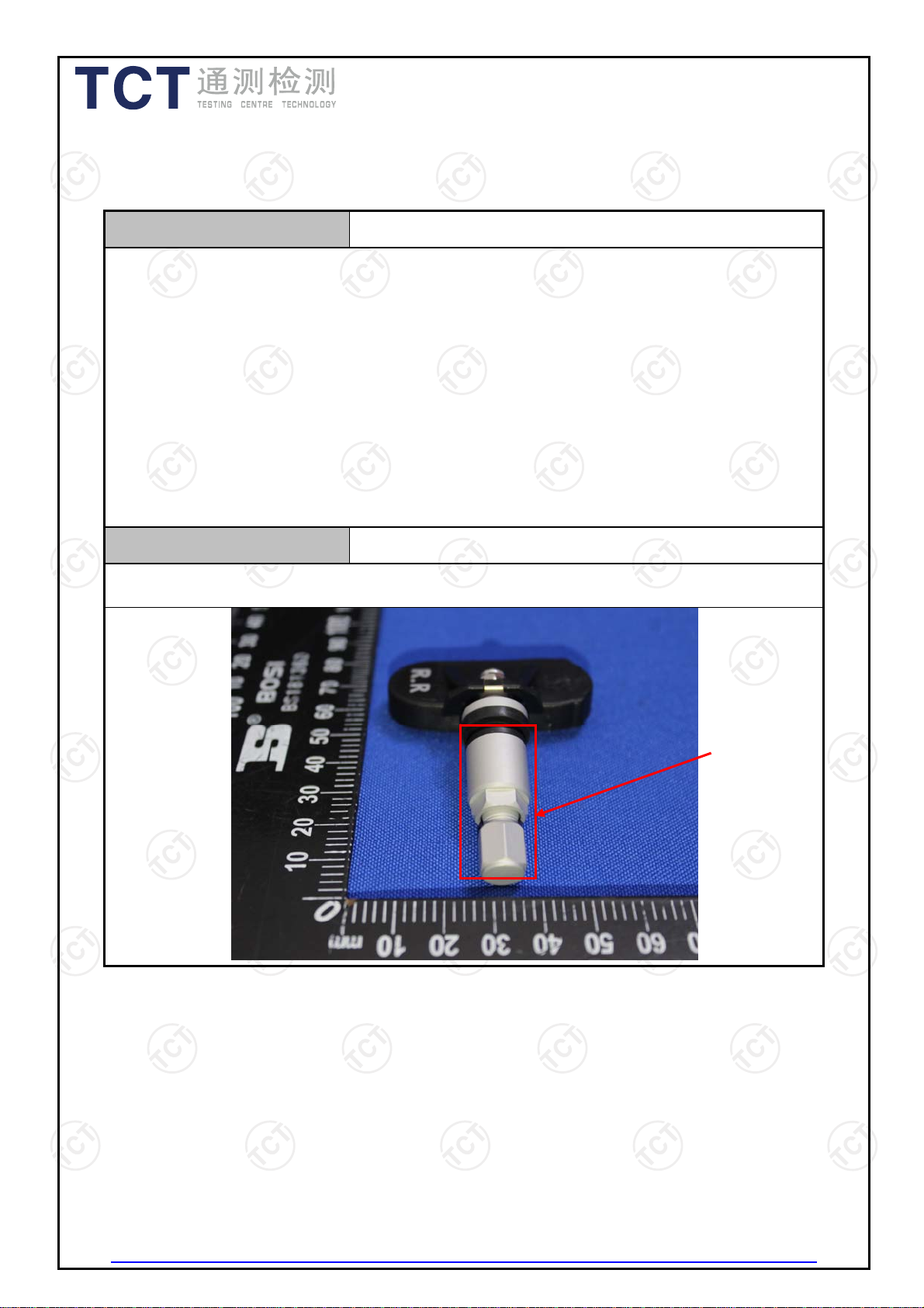
6.1. Antenna Requirement
Standard requirement:
FCC Part15 C Section 15.203 /247(c)
15.203 requirement:
An intentional radiator shall be designed to ensure that no antenna other than that
furnished by the responsible party shall be used with the device. The use of a
permanently attached antenna or of an antenna that uses a unique coupling to the
intentional radiator, the manufacturer may design the unit so that a broken antenna
can be replaced by the user, but the use of a standard antenna jack or electrical
connector is prohibited.
15.247(c) (1)(i) requirement:
(i) Systems operating in the 2400-2483.5 MHz band that is used exclusively for fixed.
Point-to-point operations may employ transmitting antennas with directional gain
greater than 6dBi provided the maximum conducted output power of the intentional
radiator is reduced by 1 dB for every 3 dB that the directional gain of the antenna
exceeds 6dBi.
E.U.T Antenna:
The antenna is an external antenna which is permanently attached, and the best case
gain of the antenna is 0dBi.
Antenna
Hotline: 400-6611-140 Tel: 86-755-27673339 Fax: 86-755-27673332 http://www.tct-lab.com
Page 8 of 28
Report No.: TCT170704E020
6.2. Conducted Emission
6.2.1. Test Specification
Test Requirement:
Test Method:
Frequency Range:
Receiver setup:
Limits:
Test Setup:
FCC Part15 C Section 15.207
ANSI C63.10:2013
150 kHz to 30 MHz
RBW=9 kHz, VBW=30 kHz, Sweep time=auto
Frequency range
(MHz)
Quasi-peak Average
Limit (dBuV)
0.15-0.5 66 to 56* 56 to 46*
0.5-5 56 46
5-30 60 50
Test Mode:
Mode 3
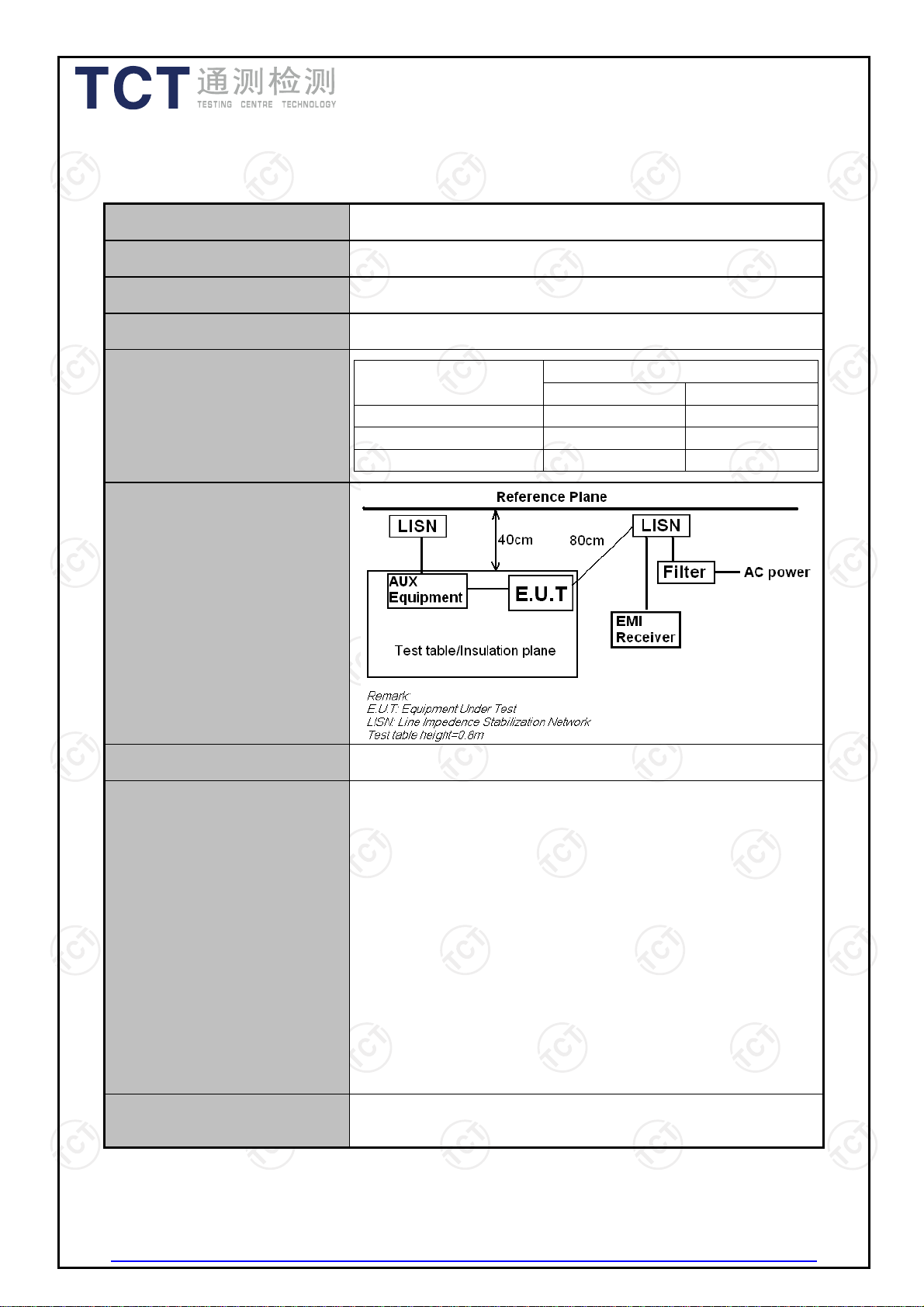
1. The E.U.T is connected to the main power through a
line impedance stabilization network (L.I.S.N.). This
provides a 50ohm/50uH coupling impedance for the
measuring equipment.
2. The peripheral devices are also connected to the main
power through a LISN that provides a 50ohm/50uH
Test Procedure:
coupling impedance with 50ohm termination. (Please
refer to the block diagram of the test setup and
photographs).
3. Both sides of A.C. line are checked for maximum
conducted interference. In order to find the maximum
emission, the relative positions of equipment and all of
the interface cables must be changed according to
ANSI C63.10:2013 on conducted measurement.
N/A; The EUT powered by battery, so this test item is
Test Result:
Hotline: 400-6611-140 Tel: 86-755-27673339 Fax: 86-755-27673332 http://www.tct-lab.com
not applicable
Page 9 of 28
 Loading...