

EGOpro Safe Move 4.0 Use And Installation Manual
EGOpro
Safe Move 4.0 KIT
Use and Installation Manual
(V04)

Table of contents
1 TABLE OF REVISIONS 4
2 COMPLIANCE 5
3 SAFETY INSTRUCTIONS 5
3.1 DISPOSAL 5
3.2 LIMITATIONS FOR USE 5
4 INTRODUCTION 6
4.1 INTENDED USE 6
4.2 SYMBOLS 6
5 BASIC KIT COMPONENTS 7
4 SYSTEM OPERATION 8
4.1 PEDESTRIAN WORKER PRE-WARNING 8
4.2 PEDESTRIAN WORKER WARNING 8
4.3 VEHICLE-VEHICLE WARNING 8
5 PLACING TAGS 9
5.1 HELMET TAG FITTING 9
5.2 WEARABLE TAG ACCESSORIES 9
5.3 PROCEDURE FOR CHANGING THE BATTERY 9
6 INSTALLATION ON THE VEHICLE 10
6.1 SYSTEM ARCHITECTURE 10
6.2 POSITIONING THE DEVICES 10
6.2.1 POSITIONING THE CONTROL UNIT (CPU) 11
6.2.2 POSITIONING THE DISPLAY 12
6.2.3 POSITIONING THE SENSORS 12
6.2.4 POSITIONING THE HUB 13
6.3 CONNECTIONS 14
6.3.1 GENERAL INSTRUCTIONS 14
6.3.2 CPU WIRING 16
6.3.3 CONNECTING SENSORS 17
6.3.4 CONNECTING THE HUB 17
6.4 INSTALLING THE SYSTEM WITH M12 CONNECTORS 19
6.4.1 LENGTH OF CONNECTIONS 20
7 STOPPING DISTANCES AND ACTIVATION DISTANCES 21

TABLE OF REVISIONS
3
The technical materials and informations contained in this document are strictly confidential and exclusive property of Advanced Microwave Engineering s.r.l.
These materials and informations are intended solely for the purpose designated and may not be used otherwise.
It is not permitted to disclose or reproduce in whole or in part without express written permission.
7.1 VEHICLE DECELERATION AND DRIVER RESPONSE DISTANCES 21
7.2 SYSTEM ACTIVATION DISTANCES. SETTING THE POWERS TRANSMITTED 23
7.3 CALCULATING THE DISTANCE IN CASE OF VEHICLE-VEHICLE COLLISION. 24
8 TURNING-ON AND CONFIGURATION 25
8.1 SYSTEM TURNING-ON 25
8.2 CONFIGURATION 26
8.2.1 STEP 1 | CONFIGURATION MENU 26
8.2.2 STEP 2 | ENTERING THE PASSWORD 26
8.2.3 STEP 3 | SENSORS 27
8.2.4 STEP 4 | SENSORS SEARCH 28
8.2.5 STEP 5 | SEARCHING SENSORS BY ID 29
8.2.6 STEP 6 | SEARCHING SENSORS BY POSITION 32
8.2.7 SEARCHING SENSORS WITHOUT ID 33
8.3 TEST 34
8.3.1 SENSOR CHECK 34
8.3.2 TAG DETECTION TEST 35
9 OPERATION MODES 36
9.1 DISPLAY OVERVIEW 36
9.2 PEDESTRIAN WORKER’S TAG DISPLAY ALARM: PRE-WARNING 37
9.3 PEDESTRIAN WORKER’S TAG DISPLAY ALARM: WARNING 38
9.4 SENSORS AND HUB DIAGNOSIS 39
9.5 DRIVER LOGIN 40
9.6 DATA ACCESS 42
10 BASIC CONFIGURATION 43
10.1 ACCESS TO MENU 43
10.2 REBOOT 44
10.3 CONFIGURATION MENU 45
10.4 CLOCK & DATE 46
10.4.1 MANUAL 46
10.4.2 AUTOMATIC 47
10.5 ALARM CONFIGURATION 48
10.6 SENSORS CONFIGURATION 50
10.6.1 SENSORS SEARCH 50
10.6.2 SENSORS POWER 51
10.6.3 LR SENSORS POWER 52
10.6.4 SR SENSORS POWER 53
10.6.5 WI-FI CHANNELS 54
10.6.6 WI-FI CHANNELS: AUTOMATIC SELECTION 55
10.6.7 WI-FI CHANNELS: MANUAL SELECTION 56
10.6.8 TAG SETTINGS 57

TABLE OF REVISIONS
4
The technical materials and informations contained in this document are strictly confidential and exclusive property of Advanced Microwave Engineering s.r.l.
These materials and informations are intended solely for the purpose designated and may not be used otherwise.
It is not permitted to disclose or reproduce in whole or in part without express written permission.
10.7 LANGUAGE 58
10.8 USERS 59
10.8.1 ADDING/EDITING USERS 60
10.8.2 IMPORTING/EXPORTING USERS 61
11 VEHICLE-VEHICLE ANTI-COLLISION MODULE 63
11.1 INSTALLATION 63
11.2 ALARM DISPLAY 63
11.3 SENSORS POWER 64
12 WIRING DIAGRAMS 65
12.1 SENSOR'S CABLE ASSEMBLY 65
12.2 SAFE MOVE CPU CONNECTIONS 66
12.3 SENSOR'S HUB CONNECTIONS 67
12.4 SENSORS CONNECTIONS 67
12.5 SAFE MOVE POWER DISTRIBUTION 68
12.6 SAFE MOVE POWER DISTRIBUTION (HIGH VOLTAGE BATTERY) 69
13 COMPONENTS OF THE SYSTEM DATA SHEET 70
13.1 SENSOR 70
13.2 HUB 71
13.3 WEARABLE TAG 72
13.4 HELMET TAG 73
13.5 CONTROL UNIT 74
13.6 DISPLAY 75
1 TABLE OF REVISIONS
Date
Rev.
Notes
10/12/2018
01
New version draft
15/01/2019
02
Updating figures-tables
14/02/2019
03
Wiring diagrams
15/02/2019
04
Section 6.2.4 update
COMPLIANCE
5
The technical materials and informations contained in this document are strictly confidential and exclusive property of Advanced Microwave Engineering s.r.l.
These materials and informations are intended solely for the purpose designated and may not be used otherwise.
It is not permitted to disclose or reproduce in whole or in part without express written permission.
2 COMPLIANCE
The manufacturer, Advanced Microwave Engineering Srl, hereby declares that the type of radio
equipment P LX HUB SR, PLX TAGSAFETY 3H, PLX TAGSAFETY 3TH, P LX SAFEMOVE DIS, P LX
SAFEMOVE CPU, PLX SAFEMOVE HUB 4, PLX SAFEMOVE HUB 4M, PLX SAFEMOVE SENS 4, PLX
SAFEMOVE SENS 4M complies with the RED directive 2014/53/EC. The full text of the EU
Declaration of Conformity is available on the following Internet address:
http://www.ameol.it/en/declaration-of-conformity/
3 SAFETY INSTRUCTIONS
3.1 DISPOSAL
Treatment of the electrical or electronic device at the end of its service life (applicable in all European Union
countries and in other European Countries with waste sorting system) This symbol indicates that the product
must be taken to a suitable collection point for recycling electrical and electronic equipment.
The EGOpro Safe MOVE 4.0 System is a set of electrical and electronic equipment
By making sure that this product is correctly disposed of, you will contribute to preventing potential negative
consequences for the environment and for health that would otherwise be caused by its improper disposal.
Recycling these materials helps to preserve natural resources. For more detailed information about this product
recycling, you can contact the municipal office, the local waste disposal service. In case of unauthorised
disposal of electrical and/or electronic equipment, the penalties foreseen by the applicable regulations could be
applied (valid only for Italy).
3.2 LIMITATIONS FOR USE
Upon installing the system in industrial vehicles, strictly follow the instructions given by the manufacturer of the vehicle contained in
the manual (electrical and mechanical connection, etc.). Only duly trained personnel must install the system. The forklift truck
should not be modified in such a way as to render the Declaration of Conformity null and void.
If the installation does not comply with the instructions contained in the manufacturer’s manual, AME shall not be held liable for
any damage to the vehicle or its poor performance.
The EGOpro Safe MOVE 4.0 system (the Product) is a safety supporting tool to prevent man-vehicle and vehicle-vehicle collisions.
This is not a personal safety system.
This system has been designed to offer an additional aid for driving. While driving, the driver’s total attention is always required. The
driver must always be read to intervene and put on the brakes and turn the steering-wheel to avoid possible collisions. The EGOpro
Safe MOVE 4.0 system does not replace the driver’s attention and judgement or need to slow down or brake in case of danger, and
it does not exonerate the purchaser and the driver from adopting the usual safety procedures foreseen.
The control of the vehicle is still under the driver’s responsibility, who must always assess the current conditions in which the vehicle
moves, paying attention to the presence of pedestrian workers, other vehicles and obstacles in general.
In no case shall AME be held liable for direct or indirect damage of any kind (personal injuries or damage to objects) suffered for any
reason whatsoever by the Purchaser or by third persons due to the use of the Product.
The EGOpro Safe MOVE 4.0 system is a product for professional use, and it may not be used in places frequented by children.

INTRODUCTION
6
The technical materials and informations contained in this document are strictly confidential and exclusive property of Advanced Microwave Engineering s.r.l.
These materials and informations are intended solely for the purpose designated and may not be used otherwise.
It is not permitted to disclose or reproduce in whole or in part without express written permission.
4 INTRODUCTION
4.1 INTENDED USE
The EGOpro Safe MOVE 4.0 System is a safety supporting system that is used for detecting the presence of pedestrian
workers and vehicles equipped with suitable devices. When any of those are detected, sound and visual signals are
generated, to which the I/O that are present in the system can be associated.
4.2 SYMBOLS
Symbol
Description
DC or AC voltage
DC voltage
symbol no. 5031 of IEC 60417 is used to indicate on the identification plate that the
equipment may only be used with direct current.
BASIC KIT COMPONENTS
7
The technical materials and informations contained in this document are strictly confidential and exclusive property of Advanced Microwave Engineering s.r.l.
These materials and informations are intended solely for the purpose designated and may not be used otherwise.
It is not permitted to disclose or reproduce in whole or in part without express written permission.
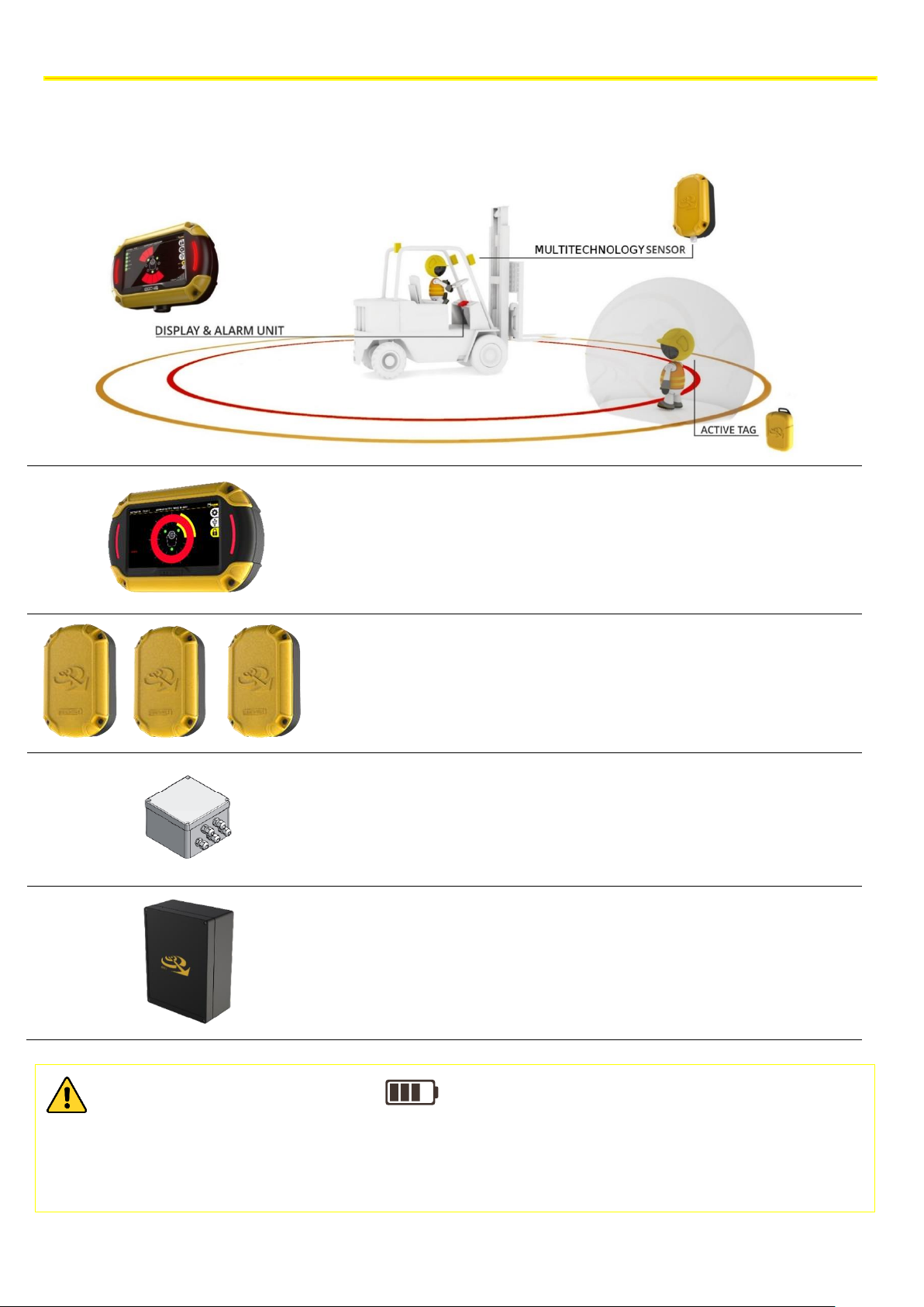
5 BASIC KIT COMPONENTS
The EGOpro Safe MOVE 4.0 basic kit consists of:
✓ 1 P LX SAFEMOVE DIS - Display with cable
(plate and joint included)
✓ 3 P LX SAFEMOVE SENS4 - SAFE MOVE 4.0
multifunction sensor.
✓ 1 P LX SAFEMOVE HUB4 - HUB SAFEMOVE 4.0.
✓ 1 P LX SAFEMOVE CPU - CPU for SAFE MOVE. (plate
and joint included)
GENERAL CONSUMPTION VALUES
• Consumption to the Hub up to 3 sensors 20W
• Consumption of CPU with active display 15W
• Consumption of CPU with display on standby 1W
SYSTEM OPERATION
8
The technical materials and informations contained in this document are strictly confidential and exclusive property of Advanced Microwave Engineering s.r.l.
These materials and informations are intended solely for the purpose designated and may not be used otherwise.
It is not permitted to disclose or reproduce in whole or in part without express written permission.
4 SYSTEM OPERATION
The Proximity Warning & Alert System solution offered by EGOpro Safe MOVE 4.0 minimises the possibilities of
accidents between forklifts and pedestrians in common working areas. By means of visual and sound alarms, the system
warns the driver, in real time, about the presence and position of pedestrian workers wearing an active TAG that enter
the danger areas around a vehicle in motion.
With the system, the driver can promptly take the most appropriate safety measures to avoid hitting other pedestrian
workers or other vehicles.
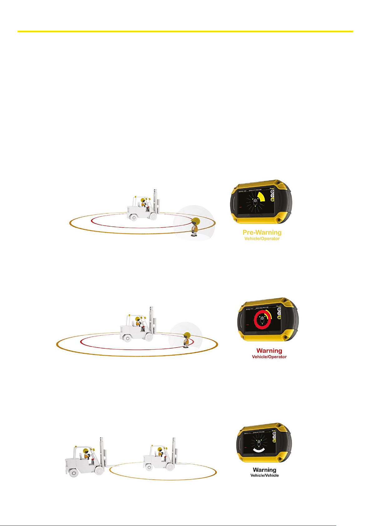
Thanks to a multifunction sensor, the system detects the pedestrian worker, who wears a TAG, in two stages:
4.1 PEDESTRIAN WORKER PRE-WARNING
PRE-WARNING| The activation range can be configured up to 50 m with the control of a relay contact.
By means of a visual and sound alarm, the system warns the driver about the presence and position of the pedestrian
worker.
4.2 PEDESTRIAN WORKER WARNING
WARNING| The activation range can be configured up to 5 m with the control of a relay contact.
By means of a visual and sound alarm, the system warns the driver about the presence of the pedestrian worker with a
red ring and the turning-on of the lateral LEDs.
4.3 VEHICLE-VEHICLE WARNING
VEHICLE-VEHICLE WARNING| When a vehicle equipped with the EGOpro Safe MOVE 4.0 system gets into the sensor
activation area. The activation range can be configured up to 100 m.
By means of a visual and sound alarm, the system warns the driver about the presence and position of the other vehicle.
PLACING TAGS
9
The technical materials and informations contained in this document are strictly confidential and exclusive property of Advanced Microwave Engineering s.r.l.
These materials and informations are intended solely for the purpose designated and may not be used otherwise.
It is not permitted to disclose or reproduce in whole or in part without express written permission.
5 PLACING TAGS
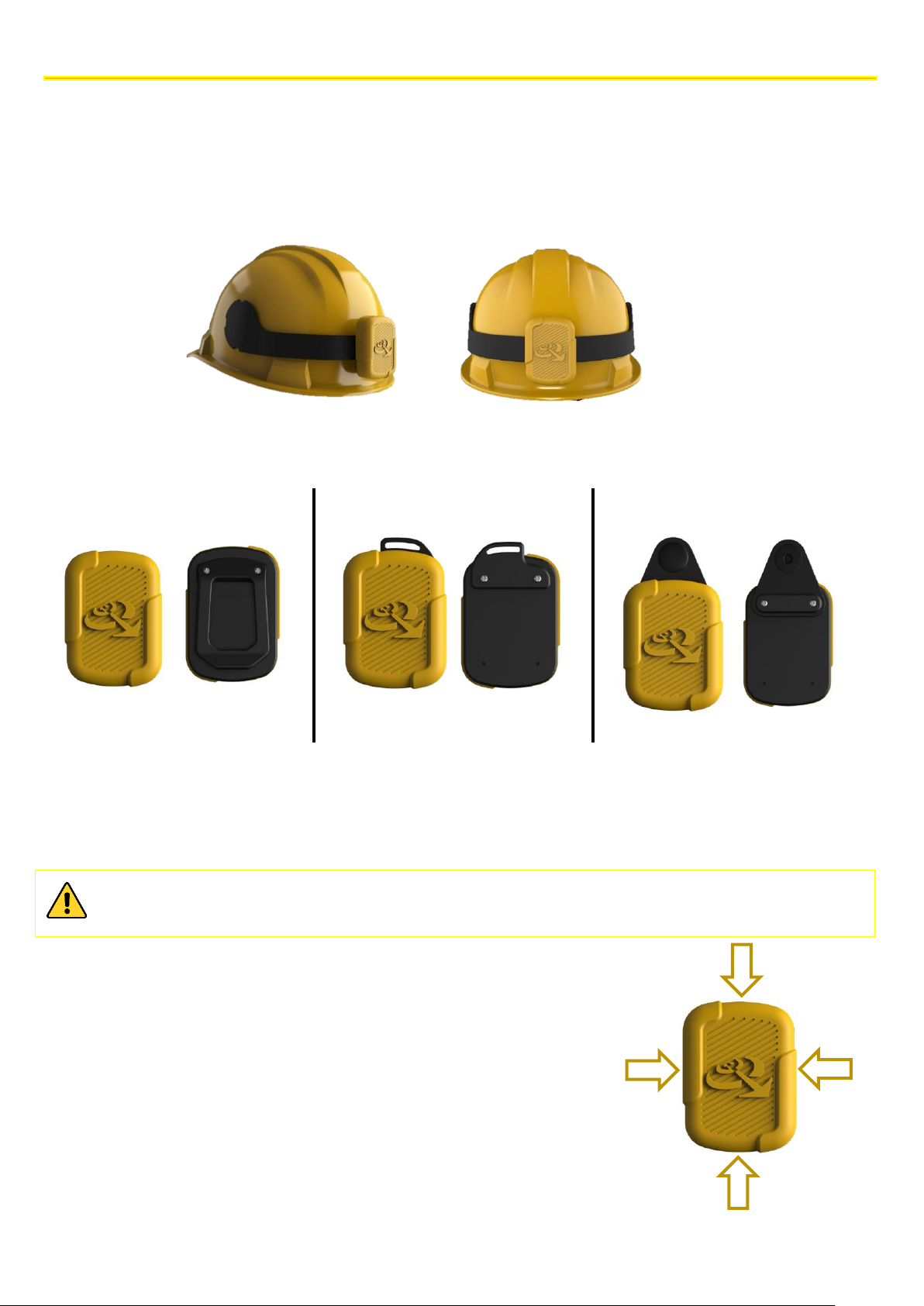
5.1 HELMET TAG FITTING
To fit the PLX TAGSAFETY 03TH Tag, you first need to clean the helmet. Then, you have to suitably remove the grease
from the surface with the napkin supplied. Now you can affix the Tag as shown in the figure.
5.2 WEARABLE TAG ACCESSORIES
The wearable Tag is supplied together with a series of accessories that guarantee a wide range of options for wearing it.
Clip for band
Slot for strap
Snap fastener
Use the screws supplied: 2.2X7
Use the screws supplied: 2.2X6
Use the screws supplied: 2.2X7
5.3 PROCEDURE FOR CHANGING THE BATTERY
The battery inside the Tag is a CR2450 button cell battery. To replace it, remove the yellow rubber part, and then
replace the battery.
While replacing the battery in the helmet tag, pay attention so as not to damage or disconnect the small
coaxial cables connected to the board.
Once the battery has been replaced, make sure that the Tag emits a long
initial sound followed by three short sounds. If this does not happen, the
device has not started correctly; contact the manufacturer.
Put the tag back in its housing, and place the soft rubber part back in its
position.
Then, press it in all directions to make the rubber part correctly adhere to
the rigid part.
INSTALLATION ON THE VEHICLE
10
The technical materials and informations contained in this document are strictly confidential and exclusive property of Advanced Microwave Engineering s.r.l.
These materials and informations are intended solely for the purpose designated and may not be used otherwise.
It is not permitted to disclose or reproduce in whole or in part without express written permission.
6 INSTALLATION ON THE VEHICLE
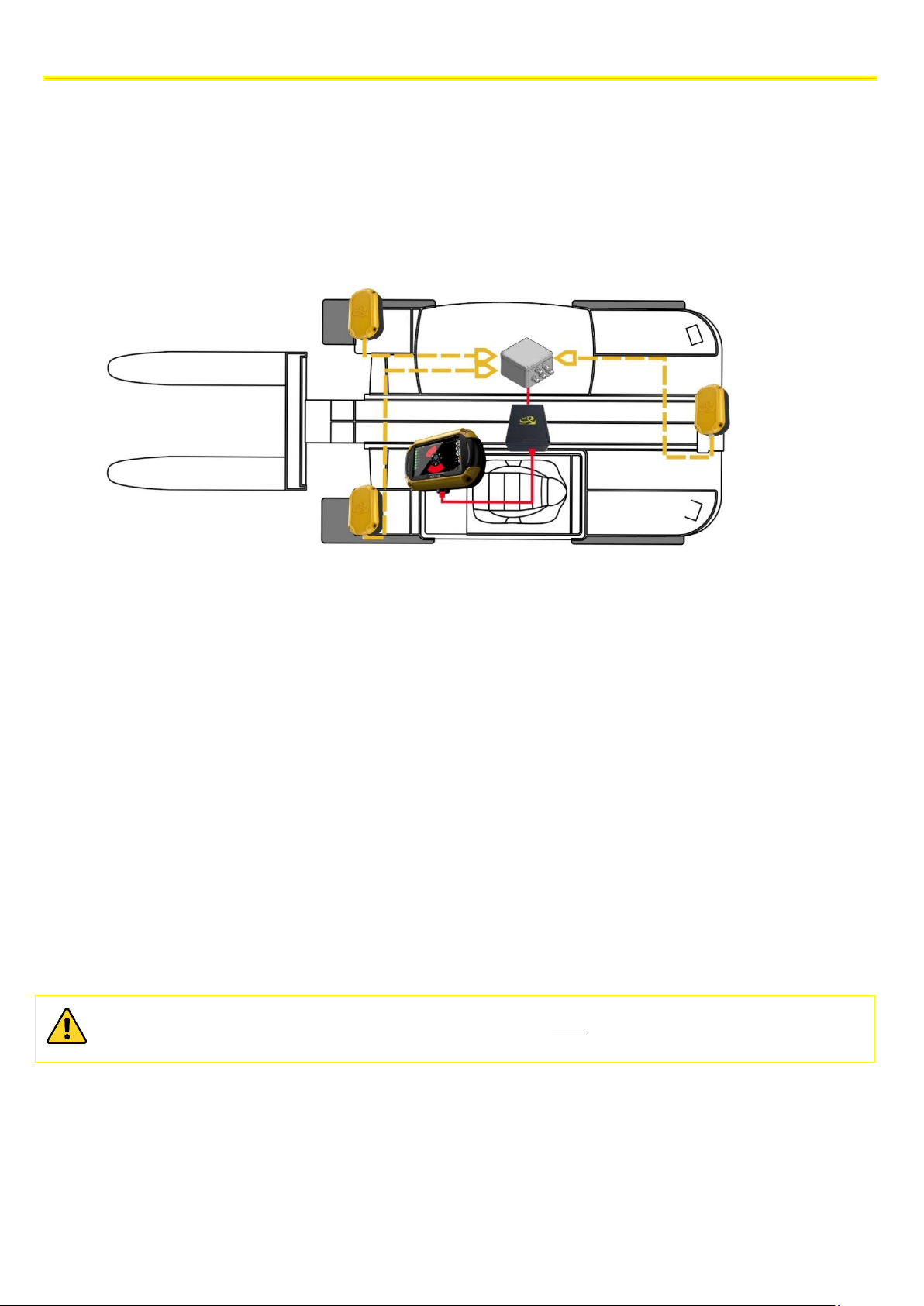
6.1 SYSTEM ARCHITECTURE
The basic KIT of the EGOpro Safe MOVE 4.0 system that is installed on the vehicle consists of the following devices:
➢ 3 Sensors
➢ 1 HUB
➢ 1 CPU
➢ 1 Display
6.2 POSITIONING THE DEVICES
To position the devices, you must take into account the system operation characteristics, the mechanical restrictions
and the IP protection degree of the devices.
For these reasons, two categories are identified:
➢ Devices outside the driver’s cabin
• Sensors are usually positioned outside the driver’s cabin, except for
exceptional cases such as exposure to high temperatures.
➢ Devices inside the driver’s cabin
• CPU and Display, due to their function and the IP protection degree, must
be inside the driver’s cabin or, in any case, in a protected position.
The HUB can be positioned either outside or inside the driver’s cabin due to both its operation and its high degree of
protection.
The 433MHz whip aerial antenna, which is present on the HUB, must be fitted outside
INSTALLATION ON THE VEHICLE
11
The technical materials and informations contained in this document are strictly confidential and exclusive property of Advanced Microwave Engineering s.r.l.
These materials and informations are intended solely for the purpose designated and may not be used otherwise.
It is not permitted to disclose or reproduce in whole or in part without express written permission.
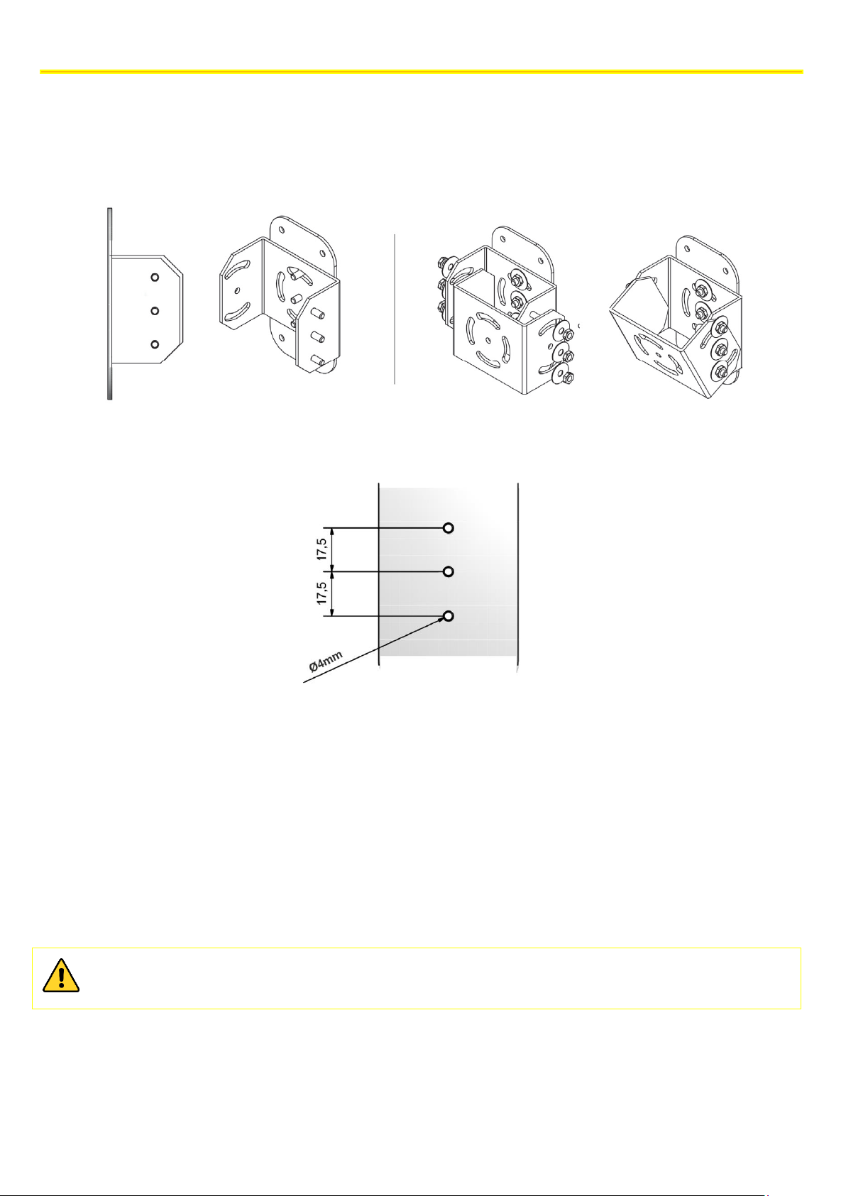
The Display and the Sensors must be correctly oriented: for this reason, they are supplied with a mounting plate and a
mechanical joint onto which the support that is necessary for holding the device must be fitted.
The joint, which is made up of 2 U-shaped mechanical parts, has been designed to be easily connected to the plate that
is present on the devices.
Find below the heights for the possible holes to be used for fixing it to the plate.
6.2.1 Positioning the control unit (CPU)
The CPU is the basic element of the system and it can be positioned at any point inside the driver's cabin. The position
of the CPU must not obstruct the driver’s and the vehicle operability, and it should be handy to connect the HUB and the
Display.
To fix the CPU, you can use the 4 holes on the box that can be accessed by removing the device cover.
When choosing the position, keep in mind that there are usable outputs on the CPU; for example, the USB port can be
used to download data and for assistance; therefore, access to them must be granted.
Remember that the CPU has an IP 20 protection degree, and the connection cable is 2.50 m long.
INSTALLATION ON THE VEHICLE
12
The technical materials and informations contained in this document are strictly confidential and exclusive property of Advanced Microwave Engineering s.r.l.
These materials and informations are intended solely for the purpose designated and may not be used otherwise.
It is not permitted to disclose or reproduce in whole or in part without express written permission.
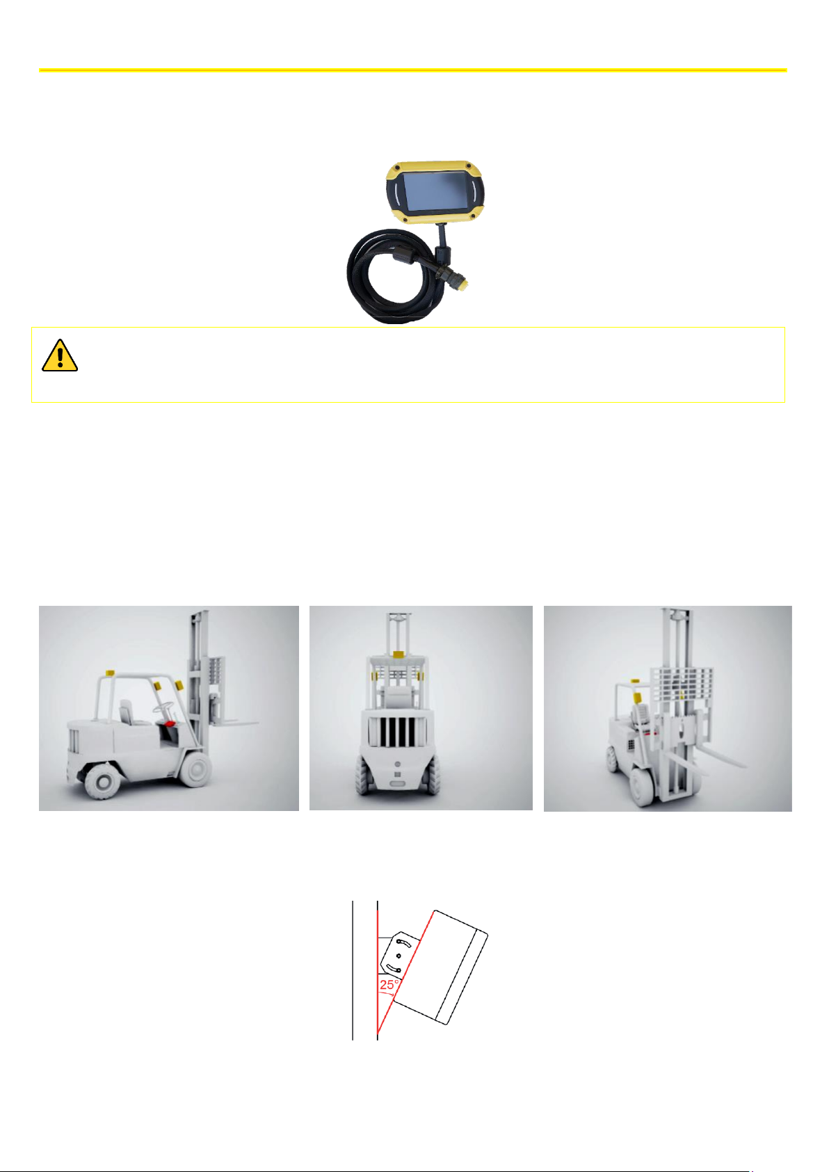
6.2.2 Positioning the Display
The Display must be positioned inside the driver’s cabin in accordance with the driver’s visibility requirements and
taking into account the CPU position: the connection cable between Display and CPU is 2.5 m long.
When installing the Display and passing the connection cable, attention must be paid so that they do not
disturb the driver’s movements and so that the driver’s visibility remains unaffected.
The Display has an IP 20 protection degree. Position it in the cabin, in an area protected from the elements.
6.2.3 Positioning the sensors
The basic Kit is made up of 3 sensors that are sufficient to cover small and medium-sized vehicles. The installation must
optimise coverage around the vehicle taking into account the type of mobility of the vehicle.
The most common installation includes 2 Sensors on the front/loading side, driven forward, and 1 Sensor on the rear
side/driven in reverse.
NOTE: the number of sensors can be extended up to 8 by adding suitable components.
The following pictures show the reference diagram for a counterbalanced forklift truck.
The sensors must be positioned on the perimeter of the vehicle in order to have maximum visibility between Sensors
and TAG. On small/medium-sized vehicles, they are usually positioned on the uprights immediately below the roof and
with a 25 ° downward inclination.
NOTE: the mechanical joint supplied can be used to obtain the desired inclination.
INSTALLATION ON THE VEHICLE
13
The technical materials and informations contained in this document are strictly confidential and exclusive property of Advanced Microwave Engineering s.r.l.
These materials and informations are intended solely for the purpose designated and may not be used otherwise.
It is not permitted to disclose or reproduce in whole or in part without express written permission.
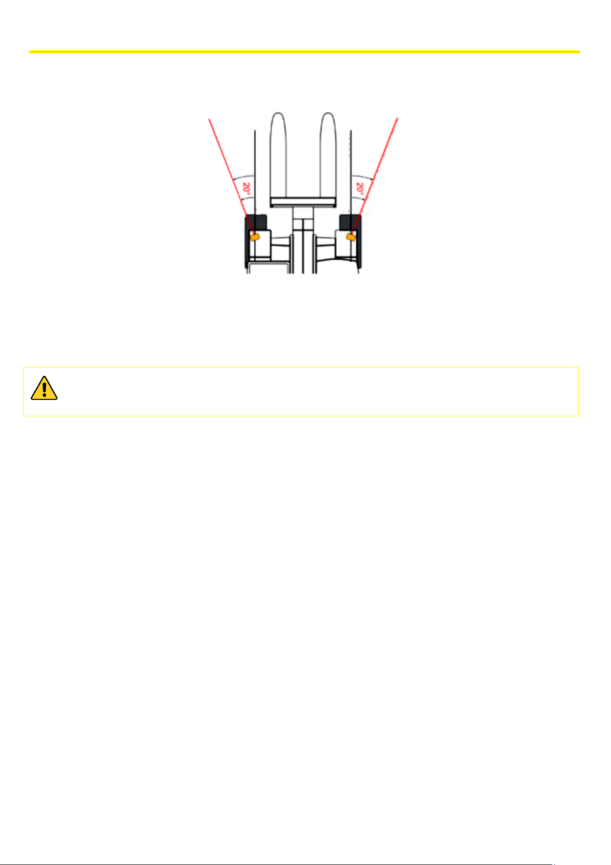
Front sensors must have a small orientation towards the outside. For example, for a counterbalanced vehicle, they must
be positioned outside the shape of the fork/gripper holder mounting, and they must have an orientation angle towards
the outside of around 20°.
6.2.4 Positioning the HUB
The HUB can be positioned at any point inside or outside the driver’s cabin, even in a hidden area, but the external RF
antenna (whip aerial antenna), connected to the HUB by means of a 1.5 m-long cable, must be outside the driver’s cabin
in vertical position.
To position the external antenna, also refer to the HUB connections (see paragraph 6.3.4).
The position of the HUB must not obstruct the driver’s and the vehicle operability, and it should be handy to
connect the Sensors and the CPU.
INSTALLATION ON THE VEHICLE
14
The technical materials and informations contained in this document are strictly confidential and exclusive property of Advanced Microwave Engineering s.r.l.
These materials and informations are intended solely for the purpose designated and may not be used otherwise.
It is not permitted to disclose or reproduce in whole or in part without express written permission.
6.3 CONNECTIONS
6.3.1 General instructions
The necessary connections on the systems can be summarised in two categories:
➢ Data Connections
➢ Power Supply Connections
Data Connections
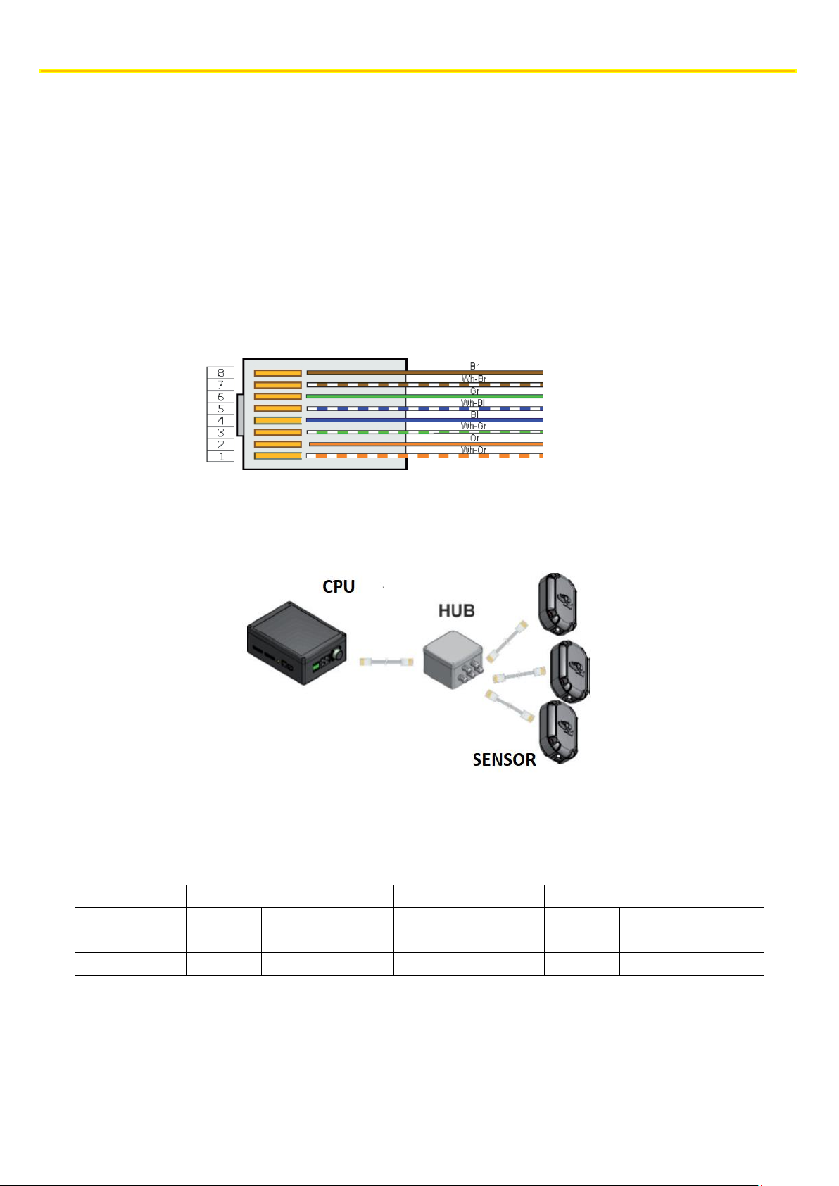
The data connection between the system devices is established with a UTP cable. As a minimum requirement, it is
recommended to use a UTP cable belonging to category 5E or above. In the case of RJ45 connections, the same
sequence of colours must be followed on each cable end, and it is recommended to use the sequence of colours
according to Standard B
The data connection is between Hub-CPU and between Sensors-Hub.
The maximum length of the connection depends on the supply voltage of the system and on the cross section of the
UTP cable (AWG). For convenience, the reference tables of both connections will be provided.
CPU-HUB Connection
HUB-SENSOR Connection
VDC
AWG 26
AWG 24
VDC
AWG 26
AWG 24
12 V
20m
40m
12 V
3m
6m
24 V
50m
100m
24 V
25m
50m
INSTALLATION ON THE VEHICLE
15
The technical materials and informations contained in this document are strictly confidential and exclusive property of Advanced Microwave Engineering s.r.l.
These materials and informations are intended solely for the purpose designated and may not be used otherwise.
It is not permitted to disclose or reproduce in whole or in part without express written permission.
Power Supply Connection
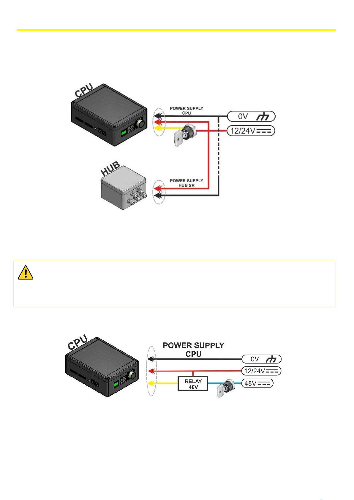
The system must be powered in direct current (VDC) ranging from 12V to 24V (±10%).
The devices to be powered are the CPU and the HUB. A direct positive wire (VIN) and a positive wire under key (VQ) must
arrive to the CPU, whereas only the direct positive wire must arrive to the HUB.
For the power supply connections, it is recommended to use an AWG 18 /0.75mm2 cable or a cable with a higher cross
section.
Within the 12÷24 VDC power supply range, the voltage of the direct positive wire (VIN) and of the line under
key (VQ) do not have to be the same.
In some cases, the voltage present on the wire under key is not within the range foreseen by the system. In
these cases, one solution would be using a relay at the same voltage available for changing over the forward
voltage
INSTALLATION ON THE VEHICLE
16
The technical materials and informations contained in this document are strictly confidential and exclusive property of Advanced Microwave Engineering s.r.l.
These materials and informations are intended solely for the purpose designated and may not be used otherwise.
It is not permitted to disclose or reproduce in whole or in part without express written permission.
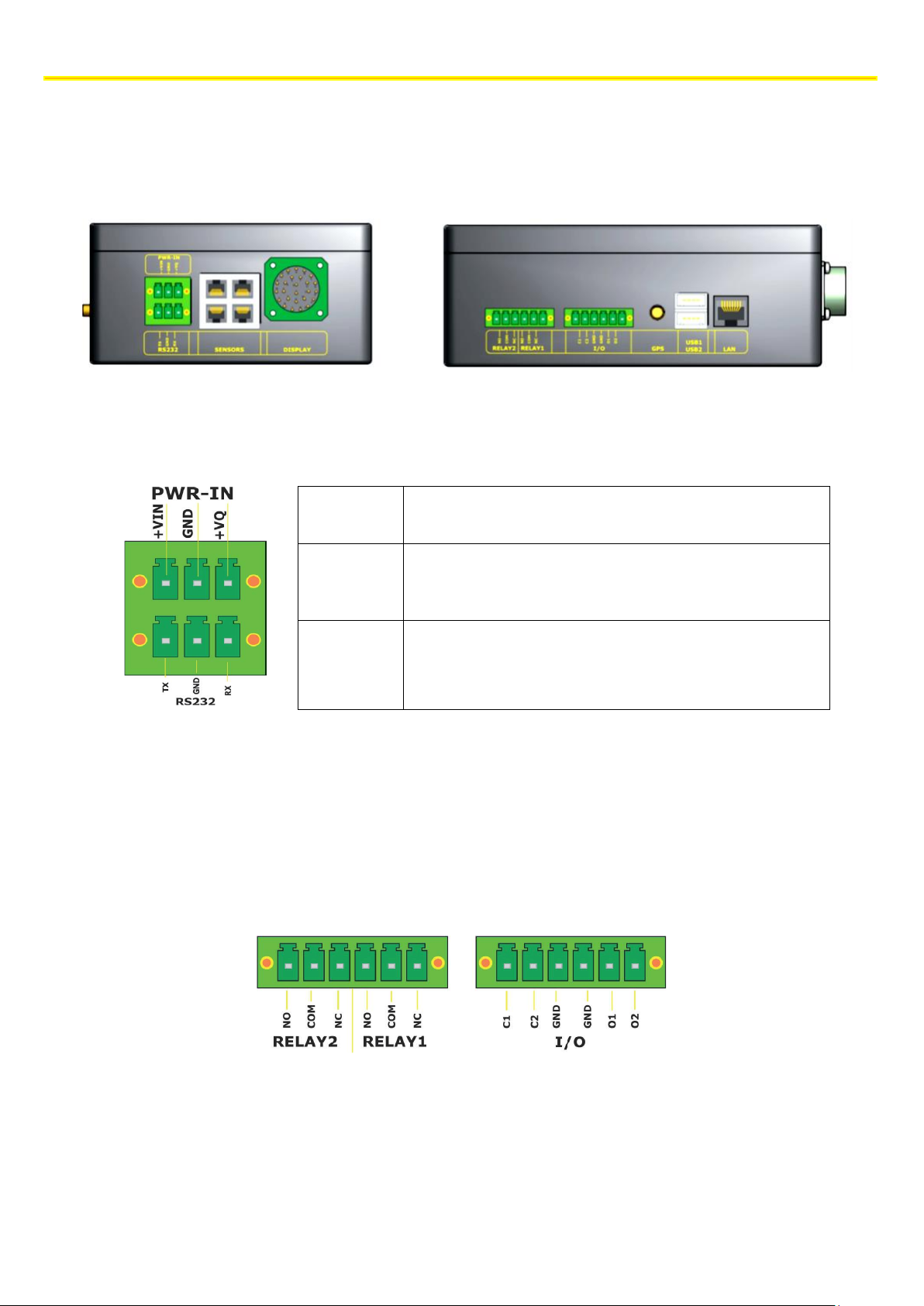
6.3.2 CPU Wiring
The CPU is powered at 12-24V, and it needs a specific +VQ line (under ignition key). The CPU remains turned on even
when the vehicle is off in low consumption regime (stand-by). Activation takes place when voltage is supplied to the VQ
terminal. This enables a quick turning-on of the system.
Power supply
/turning-on
Sensors
HUB
(RJ45)
Display
connector
Relay
I/O
GPS
Antenna
USB
LAN
RS 232
+VIN
12/24 VDC power supply
GND
Negative supply voltage
+VQ
12/24 VDC positive voltage of the turning-on signal of the
board
To connect the HUB, an UTP cable belonging to Cat. 5e or higher and one of the Sensors ports must be connected.
The CPU has 2 relays that can be controlled independently. There are 3 pins for each relay:
- NO | normally open
- C | common
- NC | normally closed.
INSTALLATION ON THE VEHICLE
17
The technical materials and informations contained in this document are strictly confidential and exclusive property of Advanced Microwave Engineering s.r.l.
These materials and informations are intended solely for the purpose designated and may not be used otherwise.
It is not permitted to disclose or reproduce in whole or in part without express written permission.
6.3.3 Connecting sensors
The sensors are connected to the HUB with UTP cables with 8 poles. The maximum connection length is related to the
supply voltage and the type of cable used
AWG 26
AWG 24
12 V
3m
6m
24 V
25m
50m
Figure 1 Maximum length of the HUB sensors connection cables according to the type of cable and the power supply
The UTP cable must be connected to the J1 connector inside the sensor box with an RJ45 connector.
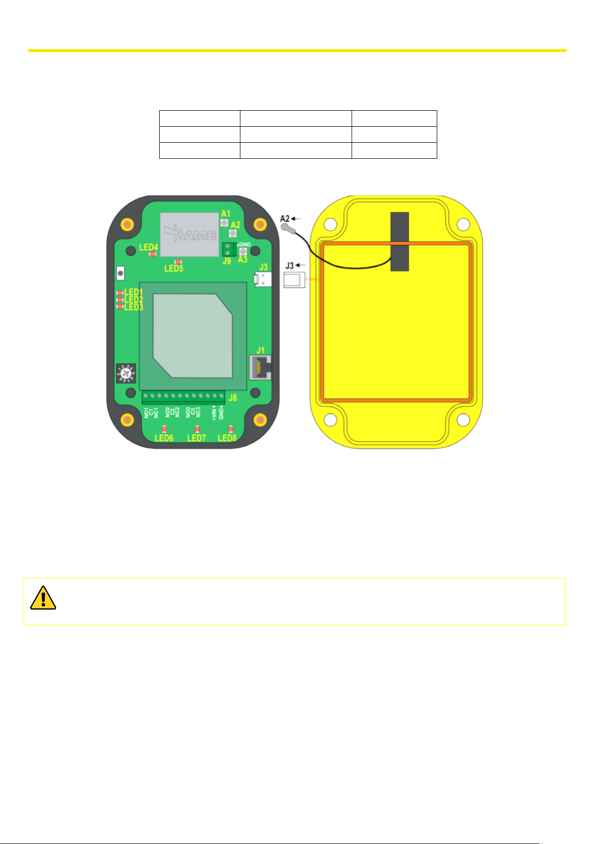
A1 – MW transmission antenna uFL connector (antenna already connected)
LED1 – vehicle-vehicle reception signal (flashing)
A2 – MW reception antenna uFL connector (antenna to be connected)
LED2 – LF transmission (flashing) and diagnostic error (fixed off)
A3 – RF test uFL connector
LED3 – ON status indicator
J9 – RF antenna connector (antenna already connected)
LED4 – MW status indicator (flashing) and diagnostic error (fixed off)
J3 – LF antenna connector (antenna to be connected)
LED5 – RF status indicator (flashing) and diagnostic error (fixed off)
J1 – data BUS and power supply connector
LED6 – Relay 1 active/inactive (ON/OFF)
J8 – relay terminal board and stand-alone power supply
LED7 – Relay 2 active/inactive (ON/OFF)
LED8 – Relay 3 active/inactive (ON/OFF)
While the sensor is closing back, make sure that the A2 and J3 connectors are connected; prevent the cables
from finishing above the patch antenna (central panel of the figure on the left). Make sure that the sealing
O-ring is placed back in its housing.
Immediately after the UTP cable comes out of the box, insert a 74271132S type or equivalent ferrite.
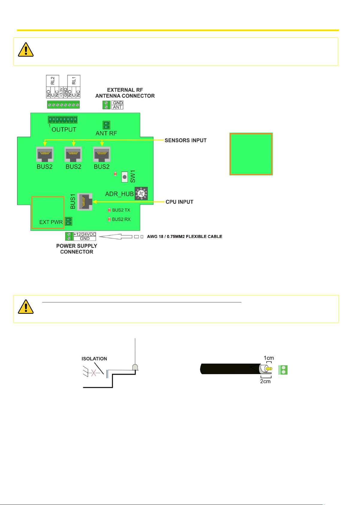
6.3.4 Connecting the HUB
Connect the sensors to BUS 2 by means of UTP cable following the indications given in the sensor connection section.
When crimping the UTP cable, follow the same sequence of colours on each cable end.
Connect the HUB to the CPU by means of the BUS 1 connector using a cable belonging to CAT5e or higher.
Connect the power supply to the EXT POWER connector with an AWG 18 / 0.75mm2 bipolar cable or a cable with a
higher cross section.
Insert the 74271132S type or equivalent ferrite on the power cable
INSTALLATION ON THE VEHICLE
18
The technical materials and informations contained in this document are strictly confidential and exclusive property of Advanced Microwave Engineering s.r.l.
These materials and informations are intended solely for the purpose designated and may not be used otherwise.
It is not permitted to disclose or reproduce in whole or in part without express written permission.
The device is powered in direct current with a voltage between 12/24 V.
The power supply to the device must be limited to a maximum of 3A. Use a
T 3 A 125 V L fuse directly fitted on the positive-pole conductor or a 3A 32V automotive fuse.
Connect the antenna supplied paying attention to the polarity with braiding on GND and the central pole on ‘ANT’
The antenna support must be kept isolated from the ground of the vehicle.
The length of the RG58 cable stripping of the antenna must observe the measurements shown in the figure.
An excessive stripping could deteriorate the RF behaviour of the system
In the case of installation on electric vehicles, it is recommended to add a power supply filter, such as Shaffner code
FN2090-3-06.
If requested, the relays present on the board can be connected following the diagram foreseen
NOTE: The default configuration indicates that:
• Relay 1 (RL1) remains active until the system detects one or more TAGS in the short-range
detection area, i.e. in Warning.
• Relay 2 (RL2) is deactivated.
The configuration of relays may be changed from the advanced menu of the CPU.
We recommend to keep the
coaxial antenna cable far from
the zone marked with the
orange square.
INSTALLATION ON THE VEHICLE
19
The technical materials and informations contained in this document are strictly confidential and exclusive property of Advanced Microwave Engineering s.r.l.
These materials and informations are intended solely for the purpose designated and may not be used otherwise.
It is not permitted to disclose or reproduce in whole or in part without express written permission.
6.4 INSTALLING THE SYSTEM WITH M12 CONNECTORS
The PLX SAFEMOVE SENS 4 and PLX SAFEMOVE HUB 4 devices are available in a version fitted with M12 connectors.
Such version has been designed in order to make the system installation and removal simpler and quicker.
The table below summarises the codes used in the system fitted with connectors.
DEVICE
CODE
HUB
PLX SAFEMOVE HUB 4M
SENSOR
PLX SAFEMOVE SENS 4M
CABLE
POLES
LENGTH (m)
AWG
CODE
RJ45-M12f CPU-HUB CONNECTION CABLE
8 5 24
M12AFRJ45CABLE5M
M12m-M12f HUB SENSOR CONNECTION
CABLE
8 5 24
M12AMFCABLE5M
HUB POWER SUPPLY AND RELAY
CONNECTION CABLE
12 5 24
M12AFPAN12P5M
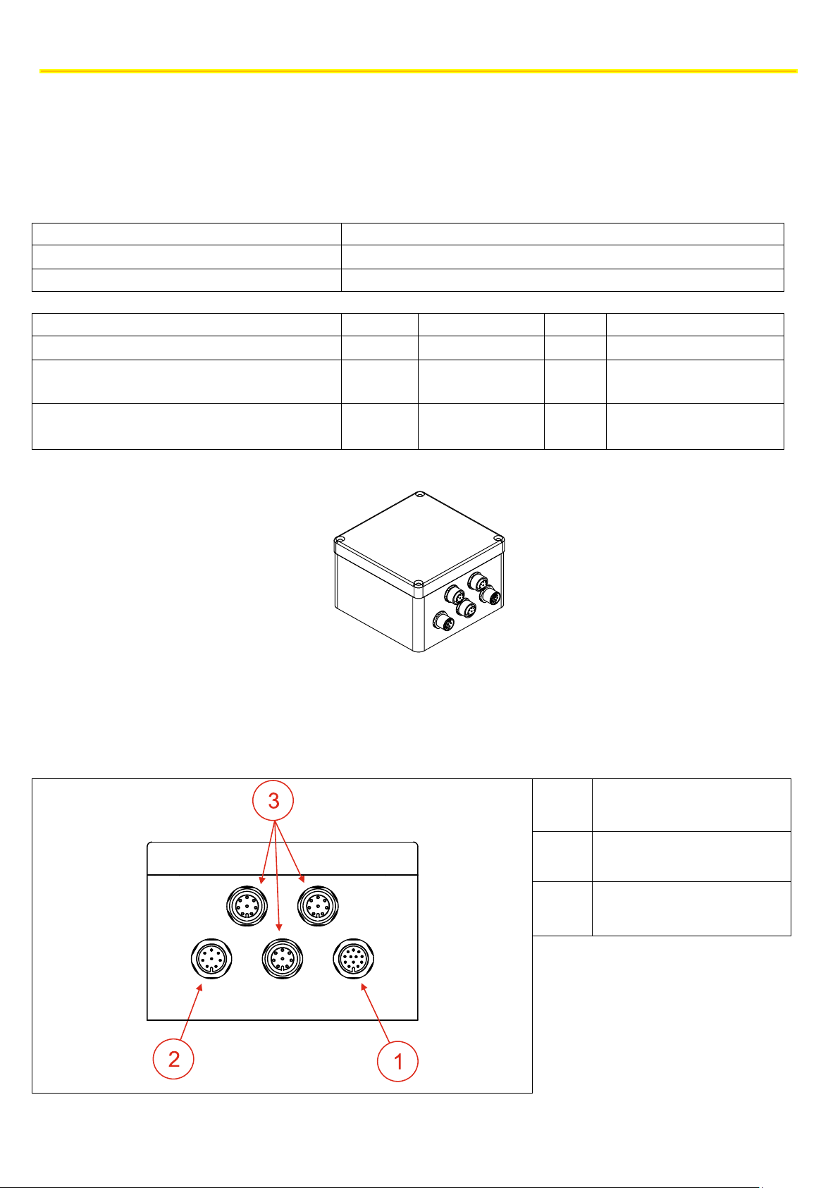
The section below indicates the functions of the different connectors and connections for the HUB power supply and
relay
1
HUB power supply and relay
connector
2
Connector for HUB-CPU
connection cable
3
Connection connectors
towards sensors
INSTALLATION ON THE VEHICLE
20
The technical materials and informations contained in this document are strictly confidential and exclusive property of Advanced Microwave Engineering s.r.l.
These materials and informations are intended solely for the purpose designated and may not be used otherwise.
It is not permitted to disclose or reproduce in whole or in part without express written permission.
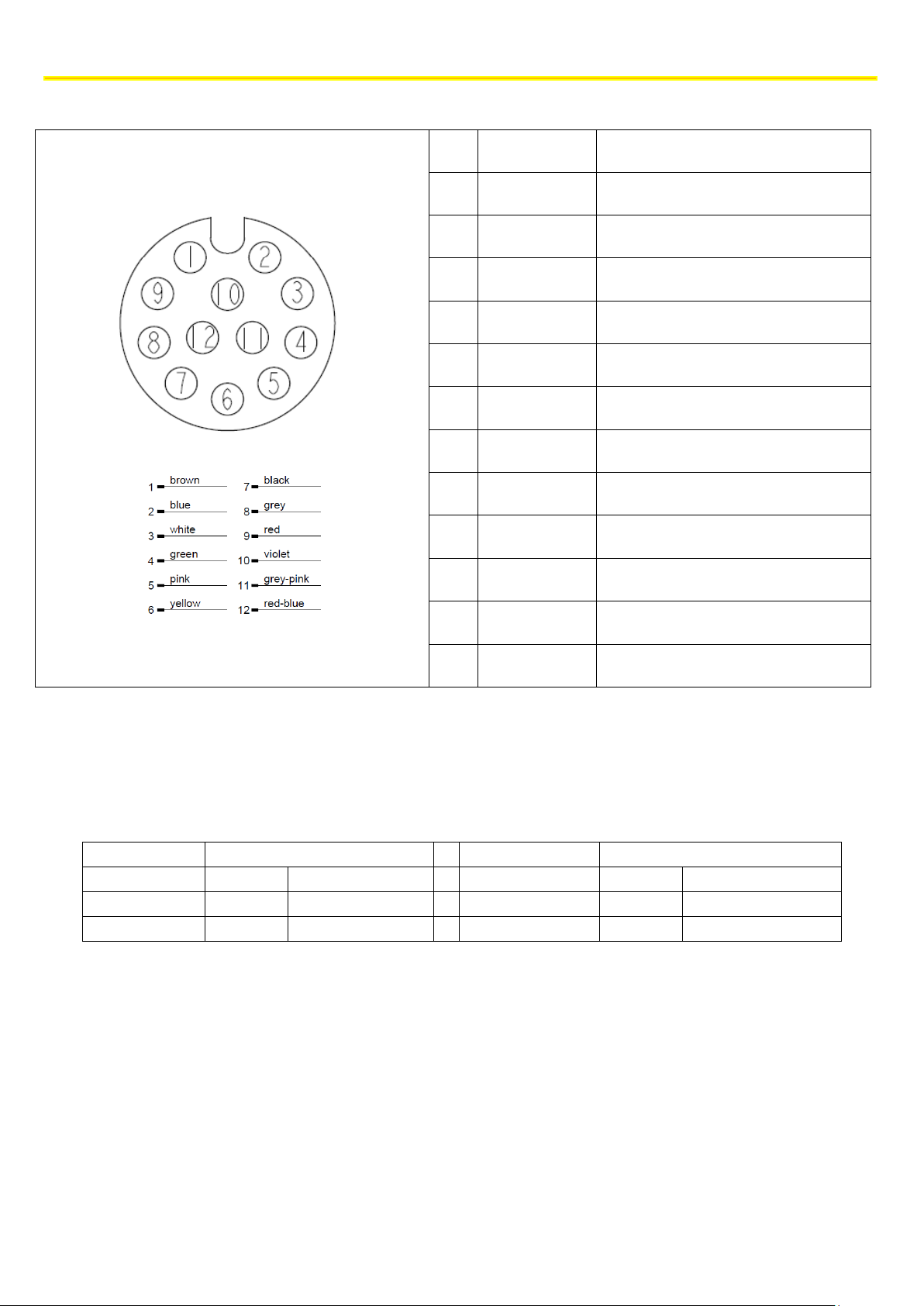
FEMALE (FRONT VIEW)
PIN
Colour
Function
1
Brown
VDC
2
Blue
VDC
3
White
GND
4
Green
GND
5
Pink
Normally Open Relay1
6
Yellow
Common Relay1
7
Black
Normally Closed Relay1
8
Grey
Normally Open Relay2
9
Red
Common Relay2
10
Violet
Normally Closed Relay2
11
Grey Pink
Not Used
12
Red Blue
Not Used
6.4.1 LENGTH OF CONNECTIONS
The cables supplied are 5 m long, and they are AWG 24. If longer connections are to be made between HUB and sensors
and between HUB and CPU, M12AMFCABLE5M cables may be used as extensions.
CPU-HUB Connection
HUB-SENSOR Connection
VDC
AWG 26
AWG 24
VDC
AWG 26
AWG 24
12 V
20m
40m
12 V
3m
6m
24 V
50m
100m
24 V
25m
50m

STOPPING DISTANCES AND ACTIVATION DISTANCES
21
The technical materials and informations contained in this document are strictly confidential and exclusive property of Advanced Microwave Engineering s.r.l.
These materials and informations are intended solely for the purpose designated and may not be used otherwise.
It is not permitted to disclose or reproduce in whole or in part without express written permission.
7 STOPPING DISTANCES AND ACTIVATION DISTANCES
When installing a safety supporting system to be used for reducing the risk of man-vehicle and vehicle-vehicle collisions,
it is necessary to take into account which activation distances have to be considered for the system operation. The
purpose of this is to adjust the system so that a truly helpful signal can be provided to the driver.
As a matter of fact, the distance at which a pedestrian worker wearing a Tag or a vehicle has to be detected in order to
give effective aid for the prevention of collisions depends on many factors such as:
• Shape and dimension of the vehicle.
• Reaction time of the detection system
• Reaction time of the driver
• Deceleration distance
• Conditions of the background
Even though formulating an accurate mathematical model of the vehicle stop physical phenomenon is very complex, the
phenomenon can be schematised following a simplified model in order to draw attention to the main physical
phenomena involved.
7.1 Vehicle deceleration and driver response distances
The space/distance a vehicle needs to stop safely must be clearly assessed. Firstly, evaluate the deceleration distancethe distance the forklift truck needs to reach zero speed starting from a given speed from the instant the braking system
is actuated. In turn, this space depends on the speed of the forklift truck, the maximum deceleration set in the
parameters of the vehicle, and the response time of the systems of the forklift truck.
Deceleration, as well as maximum speed, can be set to different values depending on the type of load, vehicle and
background. The maximum distances for industrial vehicles are standardised by ISO 6292 that sets the maximum
stopping distances from the instant when the braking system is actuated. Such values will be taken as reference. The
driver's reaction distance is to be added to the acceleration distance afterwards. Such distance is associated to the time
between the alert and the driver's action stop the vehicle. As a normal practice, this response time is estimated in 1
second. By way of an example, find below two charts with the values referring to deceleration space and total stopping
space for two types of vehicles defined in the standard.
Chart 1 Stopping distances as per ISO 6292 A1 (<16000 kg)
Speed
[km/h]
Deceleration
distance [m]
(ISO6292 A1)
Driver reaction
distance @1s [m]
Total braking
distance [m]
3
0.8
0.8
1.6 4 1.3
1.1
2.4 5 1.8
1.4
3.2 6 2.2
1.7
3.8 7 2.5
1.9
4.5
8
2.9
2.2
5.1 9 3.3
2.5
5.8
10
3.6
2.8
6.4
11
4.0
3.1
7.0
12
4.4
3.3
7.7
13
4.7
3.6
8.3

STOPPING DISTANCES AND ACTIVATION DISTANCES
22
The technical materials and informations contained in this document are strictly confidential and exclusive property of Advanced Microwave Engineering s.r.l.
These materials and informations are intended solely for the purpose designated and may not be used otherwise.
It is not permitted to disclose or reproduce in whole or in part without express written permission.
14
5.2
3.9
9.1
15
5.8
4.2
10.0
16
6.4
4.4
10.9
17
7.1
4.7
11.8
18
7.8
5.0
12.8
19
8.5
5.3
13.8
20
9.3
5.6
14.8
21
10.1
5.8
15.9
22
10.9
6.1
17.0
23
11.8
6.4
18.2
24
12.7
6.7
19.3
Chart 2 Calculation of stopping distance as per ISO 6292 A2 (<16000 kg)
Speed
[km/h]
Deceleration distance
[m] ISO6292 A2
Driver reaction
distance @1s [m]
Total braking
distance [m]
3
0.9
0.8
1.8 4 1.4
1.1
2.5 5 2.1
1.4
3.4
6
2.5
1.7
4.1
7
2.9
1.9
4.8 8 3.3
2.2
5.5 9 3.7
2.5
6.2
10
4.1
2.8
6.9
11
4.5
3.1
7.6
12
5.0
3.3
8.3
13
5.4
3.6
9.0
14
6.0
3.9
9.8
15
6.7
4.2
10.8
16
7.4
4.4
11.9
17
8.2
4.7
13.0
18
9.1
5.0
14.1
19
9.9
5.3
15.2
20
10.9
5.6
16.4
21
11.8
5.8
17.6
22
12.8
6.1
18.9
23
13.8
6.4
20.2
24
14.9
6.7
21.6

STOPPING DISTANCES AND ACTIVATION DISTANCES
23
The technical materials and informations contained in this document are strictly confidential and exclusive property of Advanced Microwave Engineering s.r.l.
These materials and informations are intended solely for the purpose designated and may not be used otherwise.
It is not permitted to disclose or reproduce in whole or in part without express written permission.
7.2 System activation distances. Setting the powers transmitted
The paragraph above dealt with how to calculate stopping distances for an industrial vehicle. When estimating the
distances at which a tag potentially in danger of collision should be detected, a distance margin should be considered as
well. A zero distance cannot and should not be set. Besides, the detection system has reaction times that have to be
taken into account. To these distances identified, we should add a value that can be calculated according to the chart
below.
Speed [km/h]
operational margin [m]
3
0.6 4 0.8 5 1.0 6 1.2 7 1.4
8
1.6 9 1.8
10
1.9
11
2.1
12
2.3
13
2.5
14
2.7
15
2.9
16
3.1
17
3.3
18
3.5
19
3.7
20
3.9
21
4.1
22
4.3
23
4.5
24
4.7
Now the detection distance we want can be calculated. For instance, if a system is installed in a forklift truck falling
within category A1, with a maximum speed of 12 km/h and manual braking, the total braking distant will be 7.7 m; some
further 2.3 m should be added as margin, to a total distance of 10 meters.
Once the desired distance is defined, adjust the power of the relevant sensors until a safe coverage for the distan ce
calculated is guaranteed. The distance previously identified is that from the interfering worker to the point of contact
that is closest to the forklift truck, which in a scenario of a front impact with a forklift truck is the fork.
Since the distance between the sensors and the first point of contact is not known a priori, and since the position of the
sensors may vary a lot, check the activation distance by applying control tests. Keep in mind that the law governs the
power set and the activation distance is not linear. Find below some graphs that show the trend of the ratio between
these two values for both long range (pre-warning) and short range (warning).
 Loading...