

EGON HARIG flamtron FL (Ex) d 07 Series, flamtron FL (Ex) d 07-T Series, flamtron FL (Ex) d 07-.-RE Series Assembly, Installation And Commissioning Instructions
Seite/Page 1 von/of 26
UV Flame Detector
Type: FL (Ex) d 07-.-..-..
10/21/2016
3
Date
Version
Betriebsanleitung Nr./
Operating Instructions No.
4.09262.9-1
Assembly, Installation and Commissioning Instructions
Maintenance, Repairs and Spare Parts
Table of contents:
1. Explanations about the operating instructions............................................................................ 2
1.1. General symbols used..............................................................................................................2
1.2. Multi-functional LED symbols used (RGB)................................................................................2
1.3. Relay symbols used (K1 - K3) .................................................................................................. 3
1.4. Fieldbus symbols used (FB) .....................................................................................................3
1.5. Structure of the warning messages, general notes ................................................................... 3
2. General safety instructions...........................................................................................................4
2.1. Safety instructions for staff .......................................................................................................4
2.2. Prior to assembly, installation and commissioning, work...........................................................4
2.3. When operating the UV flame detector.....................................................................................4
2.4. Intended scope of application...................................................................................................5
3. Assembly........................................................................................................................................6
3.1. Defining the assembly location.................................................................................................6
3.2. Tools for assembly ................................................................................................................... 7
3.3. Mounting of the UV flame detector ........................................................................................... 7
4. Installation......................................................................................................................................8
4.1. General installation................................................................................................................... 8
4.2. Opening / closing enclosure cover............................................................................................ 9
4.3. Connecting the protective conductor to the UV flame detector................................................10
4.4. Connecting the connector cable to the UV flame detector ......................................................10
5. Commissioning............................................................................................................................12
5.1. Prior to commissioning the UV flame detector type: FL (Ex) d 07-.-RE-..................................12
5.2. Functions test of the UV flame detector type: FL (Ex) d 07-.-RE-............................................ 12
5.3. Prior to commissioning the UV flame detector type: FL (Ex) d 07-.-FB-.. ................................14
5.4. Functions test of the UV flame detector type: FL (Ex) d 07-.-FB-............................................ 15
5.5. Fire alarm test of the UV flame detector type: FL (Ex) d 07-.-RE-...........................................18
5.6. Fire alarm test of the UV flame detector type: FL (Ex) d 07-.-FB-.. .........................................20
6. Maintenance ................................................................................................................................. 22
6.1. Regular maintenance tasks.................................................................................................... 22
6.2. Cleaning tasks........................................................................................................................22
7. Repairs and Spare Parts..............................................................................................................23
7.1. Repairs................................................................................................................................... 23
7.2. Spare parts.............................................................................................................................25
7.3. Threaded versions of housing top and bottom........................................................................26
Seite/Page 2 von/of 26
UV Flame Detector
Type: FL (Ex) d 07-.-..-..
10/21/2016
3
Date
Version
Betriebsanleitung Nr./
Operating Instructions No.
4.09262.9-1
1. Explanations about the operating instructions
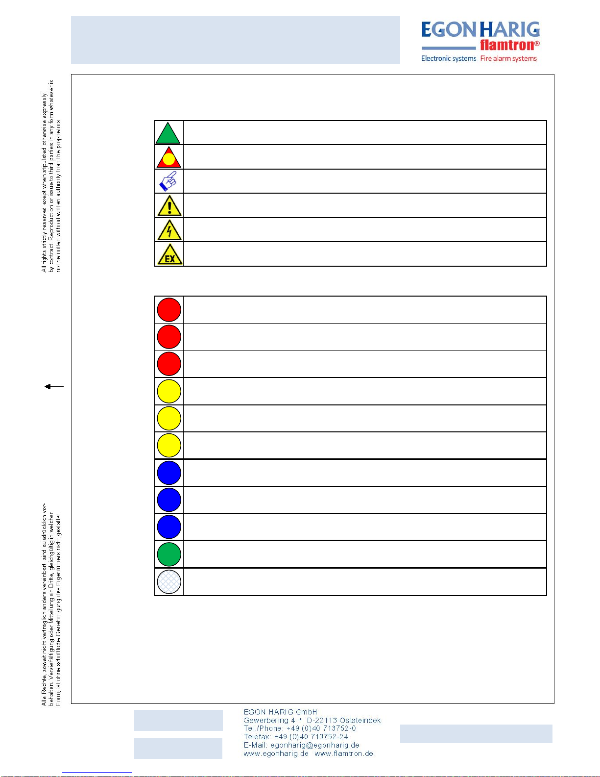
1.1. General symbols used
Tasks to be performed by the staff
Response to tasks
Notes and recommendations
WARNING
Warning of dangerous live voltage
Warning of danger of explosion - protection
1.2. Multi-functional LED symbols used (RGB)
Multi-functional LED (RGB)
Solid light
Multi-functional LED (RGB)
Blinking = clock ratio ON /OFF 1 : 1
Multi-functional LED (RGB)
Flashing = clock ratio ON /OFF 1 : 4
Multi-functional LED (RGB)
Solid light
Multi-functional LED (RGB)
Blinking = clock ratio ON /OFF 1 : 1
Multi-functional LED (RGB)
Flashing = clock ratio ON /OFF 1 : 4
Multi-functional LED (RGB)
Solid light
Multi-functional LED (RGB)
Blinking = clock ratio ON /OFF 1 : 1
Multi-functional LED (RGB)
Flashing = clock ratio ON /OFF 1 : 4
Multi-functional LED (RGB)
Flashing = clock ratio ON /OFF 1 : 4
Multi-functional LED (RGB)
OFF = is not illuminated
LED
OFF
LED
Flash
LED
Flash
LED
Blink
LED
LED
Flash
LED
Blink
LED
LED
Flash
LED
Blink
LED
Seite/Page 3 von/of 26
UV Flame Detector
Type: FL (Ex) d 07-.-..-..
10/21/2016
3
Date
Version
Betriebsanleitung Nr./
Operating Instructions No.
4.09262.9-1
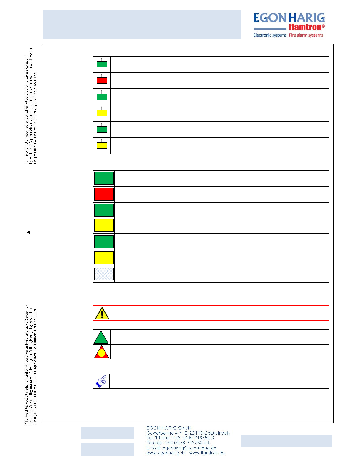
1.3. Relay symbols used (K1 - K3)
Relay – K1 (fire alarm)
Ready
Relay – K1 (fire alarm)
Fire alarm
Relay – K2 (general fault)
Ready
Relay – K2 (general fault)
General fault
Relay – K3 (max. temperature)
Ready
Relay – K2 (max. temperature)
Max. temperature
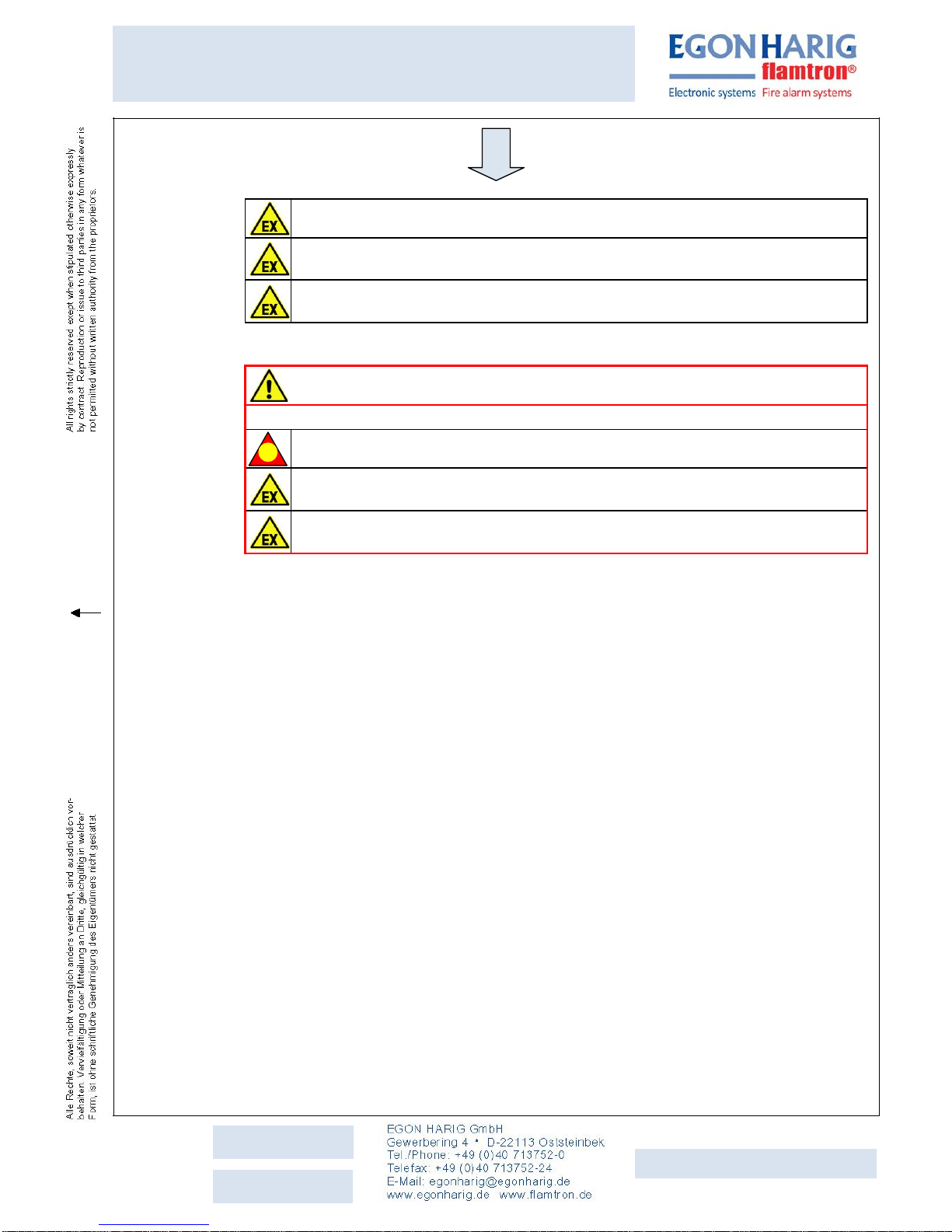
1.4. Fieldbus symbols used (FB)
Data word: Current status UV flame detector (bit 4 deleted = 0)
Ready
Data word: Current status UV flame detector (bit 4 set = 1)
Fire alarm
Data word: Current status UV flame detector (bit 5 deleted = 0) ready
Data word: Current status UV flame detector (bit 5 set = 1)
General fault
Data word: Current status UV flame detector (bit 6 deleted = 0)
Ready
Data word: Current status UV flame detector (bit 6 set = 1)
Max. temperature
DP - Slave
Failed
1.5. Structure of the warning messages, general notes
Warning messages
WARNING
Description of the danger!
Tasks to be performed by the staff
Response to tasks
General notes
Notes and recommendations
FB Master IN
DP – Slave
Failed
FB Master IN
Reg. 0002/Lo
Bit 6 = 1
FB Master IN
Reg. 0002/Lo
Bit 6 = 0
FB Master IN
Reg. 0002/Lo
Bit 5 = 1
FB Master IN
Reg. 0002/Lo
Bit 5 = 0
FB Master IN
Reg. 0002/Lo
Bit 4 = 1
FB Master IN
Reg. 0002/Lo
Bit 4 = 0
K3
K3
K2
K2
K1
K1

Seite/Page 4 von/of 26
UV Flame Detector
Type: FL (Ex) d 07-.-..-..
10/21/2016
3
Date
Version
Betriebsanleitung Nr./
Operating Instructions No.
4.09262.9-1
2. General safety instructions
2.1. Safety instructions for staff
The operating instructions contains basic safety instructions that must be observed for
assembly, commissioning, testing, maintenance, repairs and for trouble.
Failure to observe them may result in injuries or damage.
WARNING
Unauthorized work on UV flame detector!
May result in injuries or damage.
Work such as:
Assembly, installation, commissioning, testing, maintenance, repairs and
troubleshooting must only be performed by trained personnel.
2.2. Prior to assembly, installation and commissioning, work
Read operating instructions completely.
If anything is unclear, please contact Egon Harig GmbH.
The national erection and installation regulations apply.
such as IEC/EN 60079-14
2.3. When operating the UV flame detector
WARNING
Never operate the UV flame detector without a protective grille or if the grille is
damaged!
May result in injuries or damage.
The UV flame detector must not be put into operation or operated without a
protective grille or if the grille is damaged, risk to the explosion protection.
Observe the safety instructions in the operating manual.
Observe all national safety and accident prevention regulations.
Only operate the UV flame detector in accordance with the output data as
shown
on the name plate and in the corresponding datasheets.
Drawing no.: 4.09262.10-1 or 4.09262.13-1 or 4.09262.14-1 or 4.09262.15-1
Any work not described in this operating manual require
our consent in advance.
Seite/Page 5 von/of 26
UV Flame Detector
Type: FL (Ex) d 07-.-..-..
10/21/2016
3
Date
Version
Betriebsanleitung Nr./
Operating Instructions No.
4.09262.9-1
Damage to the UV flame detector may override the explosion protection.
Alterations or changes made to the UV flame detector that impact the explosion
protection are prohibited.
Only assemble and operate the UV flame detector in undamaged, dry and clean
state
2.4. Intended scope of application
WARNING
Only operate the UV flam
e detector as intended!
Failure to do so will void the manufacturer's liability and warranty.
Only use the UV flame detector in compliance with the operating conditions
defined in this operating manual.
The UV flame detector may only be operated in potentially explosive
atmosphere in accordance with these operating instructions.
Seite/Page 6 von/of 26
UV Flame Detector
Type: FL (Ex) d 07-.-..-..
10/21/2016
3
Date
Version
Betriebsanleitung Nr./
Operating Instructions No.
4.09262.9-1
3. Assembly
3.1. Defining the assembly location
If exposed to all weather conditions, we recommend to equip the UV flame
detector with a
Weather protection hood, type: WH d 07, part ID: 80621.
For dimensions and mounting measurements of the UV flame detector, refer to:
Drawing no.: 3.09262.1-1 or 3.09262.10-1
When defining the installation location of the UV flame detector, account for the
visual viewing angle of the device,
vertically / horizontally, it is: α = 90°
However, the response sensitivity reduces towards the sides.
For this reason, face the UV flame detector directly towards the
object to be monitored.
Because the flame detection depends on the intensity of the flame and its
distance to the UV flame detector, it must be installed as close as possible to
the object to be monitored.
For space monitoring, account for the visual viewing angle of the detector.
If the device is to be installed in outside areas or in roof-covered halls (tank
storage monitoring, gas stations or similar),
please be advised that even such gas flaring flames, gas and welding flames as
well as electric arcs of
electric welding devices and electric railway overhead lines that are far away
can trigger the detector. In cases such as these, it is critical to coordinate the
sensitivity setting of the detector with the plant in advance.
In rooms with a high level of dirt content (dusty atmosphere or with high oil
content), install the UV flame detector so that it is
preferably ventilated with fresh
air and so that no oil deposits or dust can form on the viewing pane.
Seite/Page 7 von/of 26
UV Flame Detector
Type: FL (Ex) d 07-.-..-..
10/21/2016
3
Date
Version
Betriebsanleitung Nr./
Operating Instructions No.
4.09262.9-1
S L
Ground screw = M6
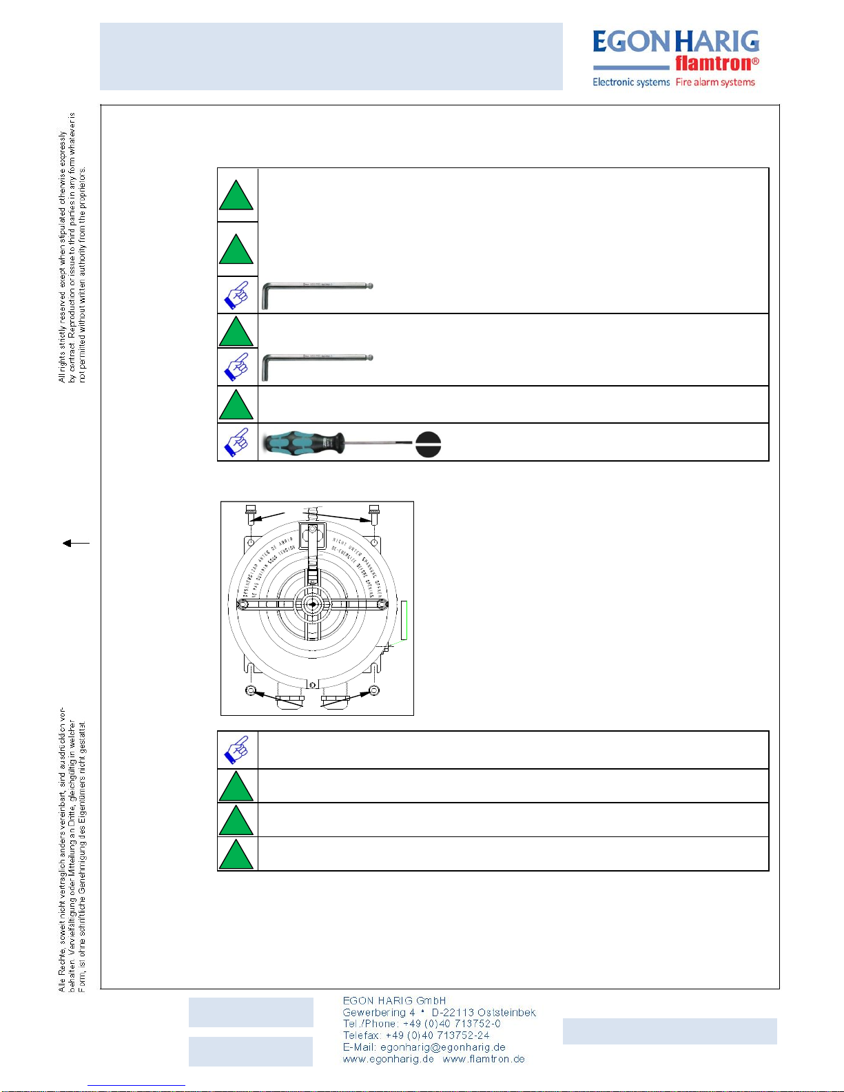
3.2. Tools for assembly
The standard tool set of a mechatronics engineer are sufficient for assembly.
We recommend to also carry the following tools.
For mounting the UV flame detector type:when using
M6 DIN 912 socket head cap screws, DIN 6798 serrated lock washers and DIN
125 plain washers.
For removing and mounting the protective grille to the UV flame detector for the
M6 DIN 912 socket head cap screws, DIN 6798 serrated lock washers and
DIN 125 plain washers. Material: V2A
Allen wrench
(Allen key) with ball head, 5.0 mm
For all other socket head cap screws on and in the UV flame detector.
Allen wrench
(Allen key) with ball head, 2.5 mm
For all M3 threaded studs (slotted) on the UV flame detector and for all
connecting terminals in the push-in direct plug technology.
Screw driver, slotted,
Size: 0,5 x 3,0 x 80 mm
3.3. Mounting of the UV flame detector
(2)
(1)
We recommend the use of M6 DIN 912 socket head cap screws in suitable
length, DIN 6798 serrated lock washers and DIN 125 plain washers.
(1) Set the UV flame detector onto both screws.
(2) Fasten the UV flame detector with two more screws.
Tighten all screws.
Seite/Page 8 von/of 26
UV Flame Detector
Type: FL (Ex) d 07-.-..-..
10/21/2016
3
Date
Version
Betriebsanleitung Nr./
Operating Instructions No.
4.09262.9-1
4. Installation
4.1. General installation
WARNING
Installation work by skilled personnel only!
Installation work must only be performed by authorized personnel with the
relevant training.
Observe any national provisions that apply in the country of operation.
WARNING
Danger as a result of unacceptable screwed cable glands!
If unacceptable screwed cable glands are used,
EX protection is no longer guaranteed.
Only use screwed cable glands that are approved for the ignition
protection type and the type of cable routing.
Observe the package insert with technical information for the installed
screwed cable glands.
WARNING
Danger as a result of open drill holes or unused screwed cable glands!
The
EX protection
can no longer be guaranteed if there are any open
drill holes or unused screwed cable glands on the UV flame detector.
Close any open drill holes or unused screwed cable glands using blind
plugs certified according to Directive 94/9/EC. Do not forget to install a
Seal between the enclosure and the blind
plug. Observe the temperature resistance of the Seal
of -40°C to +125°C.
WARNING
Danger as a result of damaged threads that lead into the pressure tight interior
of the UV flame detector!
If threads are damaged, the ignition transmission resistant gap is no
longer guaranteed.
Carefully set down the enclosure cover or rather carefully set it onto the
enclosure.
Replace any enclosure cover or enclosure with damaged threads
immediately!
 Loading...