

Page 1
WARNING: To reduce the risk of injury, the user must read and understand the
Operator’s Manual before using this product. Save these instructions for future reference.
Español p. 53
Français p. 26
OPERATOR'S MANUAL
EDGER
ATTACHMENT
MODEL NUMBER EA0800/EA0800-FC
EXCLUSIVELY FOR USE WITH
EGO POWER+ POWER HEAD
PH1400/PH1400-FC
Page 2

EDGER ATTACHMENT — EA0800/EA0800-FC2
TABLE OF CONTENTS
Safety Symbols ..........................................4
Safety Instructions ......................................5-8
Introduction .............................................8
Specifications ...........................................9
Packing List .............................................9
Description .........................................10-11
Assembly ...........................................12-13
Operation ...........................................14-16
Maintenance ........................................17-22
Troubleshooting .........................................23
Warranty ...........................................24-25
Page 3

EDGER ATTACHMENT — EA0800/EA0800-FC 3
READ ALL INSTRUCTIONS!
READ & UNDERSTAND
OPERATOR'S MANUAL
WARNING:
Some dust created by power sanding, sawing, grinding, drilling
and other construction activities contains chemicals known to the state of California
to cause cancer, birth defects or other reproductive harm. Some examples of these
chemicals are:
◾
Lead from lead-based paints
◾
Crystalline silica from bricks and cement and other masonry products, and
◾
Arsenic and chromium from chemically-treated lumber.
Your risk from these exposures varies, depending on how often you do this type of
work. To reduce your exposure to these chemicals: work in a well ventilated area, and
work with approved safety equipment, such as those dust masks that are specially
designed to filter out microscopic particles.
Page 4
EDGER ATTACHMENT — EA0800/EA0800-FC4
SAFETY SYMBOLS
The purpose of safety symbols is to attract your attention to possible dangers. The
safety symbols and the explanations with them deserve your careful attention and
understanding. The symbol warnings do not, by themselves, eliminate any danger.
The instructions and warnings they give are no substitutes for proper accident
prevention measures.
WARNING:
Be sure to read and understand all safety instructions in this
Operator’s Manual, including all safety alert symbols such as “DANGER,” “WARNING,”
and “CAUTION” before using this tool. Failure to following all instructions listed below
may result in electric shock, fire, and/or serious personal injury.
SYMBOL MEANING
SAFETY ALERT SYMBOL:
Indicates DANGER, WARNING, OR CAUTION.
May be used in conjunction with other symbols or pictographs.
WARNING!
The operation of any power tools can result in foreign
objects being thrown into your eyes, which can result in severe eye
damage. Before beginning power tool operation, always wear safety
goggles or safety glasses with side shield and a full face shield when
needed. We recommend a Wide Vision Safety Mask for use over
eyeglasses or standard safety glasses with side shields. Always use eye protection
which is marked to comply with ANSI Z87.1.
Page 5
EDGER ATTACHMENT — EA0800/EA0800-FC 5
SAFETY INSTRUCTIONS
This page depicts and describes safety symbols that may appear on this product. Read,
understand, and follow all instructions on the machine before attempting to assemble
and operate it.
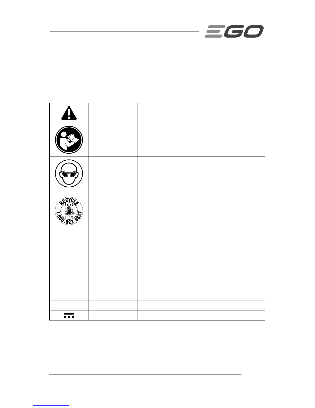
Safety Alert Indicates a potential personal injury hazard.
Read &
Understand
Operator's
Manual
To reduce the risk of injury, user must read and
understand the operator’s manual before using
this product.
Eye Protection
Always wear safety goggles or safety glasses
with side shields and a full face shield when
operating this product.
Recycle Symbols
This product uses lithium-ion (Li-ion) batteries.
Local, state, or federal laws may prohibit disposal
of batteries in ordinary trash. Consult your
local waste authority for information regarding
available recycling and/or disposal options.
IPX4
Ingress Protection
Degree
Protection from splashing water
V Volt Voltage
mm Millimeter Length or size
cm Centimeter Length or size
in. Inch Length or size
kg Kilogram Weight
lb Pound Weight
Direct Current Type or a characteristic of current
Page 6

EDGER ATTACHMENT — EA0800/EA0800-FC6
IMPORTANT SAFETY INSTRUCTIONS
WARNING!
When using electric gardening appliances, basic safety precautions
should always be followed to reduce the risk of fire, electric shock, and personal injury,
including the following:
READ ALL INSTRUCTIONS
DANGER!
Do not rely on the tool’s insulation against electric shock. To reduce
the risk of electrocution, never operate the tool in the vicinity of any wires or cables
which may carry electric current.
CAUTION!
Wear appropriate personal hearing protection during use. Under some
conditions and durations of use, noise from this product may contribute to hearing loss.
◾
Avoid Dangerous Environment – Don’t use appliances in damp or wet
locations.
◾
Keep Children Away - All visitors should be kept at a distance away from work
area.
◾
Dress Properly - Do not wear loose clothing or jewelry. They can be caught in
moving parts. Use of rubber gloves and substantial footwear is recommended
when working outdoors. Wear protective hair covering to contain long hair.
◾
Use Safety Glasses - Always use face or dust mask if operation is dusty.
◾
Use Right Appliance - Do not use appliance for any job except that for which it
is intended.
◾
Don’t Force Appliance - It will do the job better and with less likelihood of a risk
of injury at the rate for which it was designed.
◾
Don’t Overreach - Keep proper footing and balance at all times.
◾
Stay Alert - Watch what you are doing. Use common sense. Do not operate the
edger when you are tired.
◾
Do not operate the edger while under the influence of alcohol or drugs.
◾
Keep guards in place and in working order.
◾
Keep blades sharp. Replace dull or worn blade; do not attempt to sharpen.
◾
Keep hands and feet away from the cutting area.
◾
Never stand or have any part of your body in line with the path of the
edger blade.
Page 7

EDGER ATTACHMENT — EA0800/EA0800-FC 7
◾
Store Idle Appliances Indoors - When not in use, appliances should be stored
indoors in a dry and high or locked-up place with the battery pack removed- out
of reach of children.
◾
Maintain Appliance with Care - Keep cutting edge sharp and clean for best
performance and to reduce the risk of injury. Follow instructions for lubricating
and changing accessories. Keep handles dry, clean, and free from oil and grease.
◾
Check Damaged Parts - Before further use of the product, a guard or other part
that is damaged should be carefully checked to determine that it will operate
properly and perform its intended function. Check for alignment of moving parts,
binding of moving parts, breakage of parts, mounting, and any other condition
that may affect its operation. A guard or other part that is damaged should be
properly repaired or replaced by an authorized service center unless indicated
elsewhere in this manual.
◾
Clear the area to be cut before each use. Remove all objects such as rocks,
broken glass, nails, wire, or string that can be thrown or become entangled in the
cutting attachment.
◾
Always hold the edger firmly, with both hands on the handles, while
operating. Wrap your fingers and thumbs around the handles.
◾
Avoid Accidentally Starting - Don’t carry the edger with your finger on the
trigger.
◾
Do not operate the edger in gaseous or explosive atmospheres. Motors in
these appliances normally spark, and the sparks might ignite fumes.
◾
Do not use the edger on or near graveled surfaces.
◾
Damage to Edger - If you strike a foreign object with the edger, stop the tool
immediately, check for damage and have any damage repaired before further
operation is attempted. Do not operate with a broken guard or blade.
◾
Replace a cracked, damaged or worn-out blade immediately, even if
damage is limited to superficial cracks. Such attachments may shatter at
high speed and cause serious or fatal injury.
◾
Do not charge the battery pack in rain, or in wet locations.
◾
Use only with the battery packs and chargers listed below:
BATTERY PACK CHARGER
BA1120, BA1120-FC, BA1400, BA1400-FC,
BA2240, BA2240-FC, BA2800, BA2800-FC,
BA4200, BA4200-FC
CH2100, CH2100-FC,
CH5500, CH5500-FC
◾
Use Only With The 56V Lithium-Ion Power Head PH1400/PH1400-FC.
Page 8

EDGER ATTACHMENT — EA0800/EA0800-FC8
◾
Do not dispose of the battery in a fire. The cells may explode. Check with
local codes for possible special disposal instructions.
◾
Do not open or mutilate the battery. Released electrolyte is corrosive and
may cause damage to the eyes or skin. It may be toxic if swallowed.
◾
Exercise care in handling batteries in order not to short the battery with
conducting materials such as rings, bracelets, and keys. The battery or
conductor may overheat and cause burns.
◾
Replacement Parts - When servicing, use only identical EGO replacement parts.
Use of any other accessory or attachment may increase the risk of injury.
◾
Battery tools do not have to be plugged into an electrical outlet;
therefore, they are always in operating condition. Be aware of possible
hazards even when the tool is not operating. Take care when performing
maintenance or service.
◾
Remove or disconnect the battery pack before servicing, cleaning or
removing material from the product.
◾
Do not incinerate the appliance even if it is severely damaged. The
batteries can explode in a fire.
◾
Do not expose a battery pack or tool to fire or excessive temperature.
Exposure to fire or temperature above 212 °F (100°C) may cause explosion.
◾
Do not wash with a hose; avoid getting water in motor and electrical
connections.
◾
If situations occur that are not covered in this manual, use care and
good judgment. Contact the EGO Customer Service Center for assistance.
◾
Save these instructions. Refer to them frequently and use them to instruct
others who may use this tool. If you lend this tool to someone else, also lend
these instructions to them to prevent misuse of the product and possible injury.
SAVE THESE INSTRUCTIONS!
NOTE: SEE YOUR POWER HEAD OPERATOR’S MANUAL FOR
ADDITIONAL SPECIFIC SAFETY RULES.
INTRODUCTION
Congratulations on your selection of the EGO EDGER ATTACHMENT. It has been
designed, engineered and manufactured to give you the best possible dependability
and performance.
Should you experience any problem you cannot easily remedy, please contact EGO
customer service center 1-855-EGO-5656.
Page 9

EDGER ATTACHMENT — EA0800/EA0800-FC 9
This manual contains important information on to the safe assembly, operation and
maintenance of your product. Read it carefully before using the product. Keep this
manual handy so you can refer to it at any time.
SERIAL NUMBER _____________________ DATE OF PURCHASE _________________
YOU SHOULD RECORD BOTH SERIAL NUMBER AND DATE OF PURCHASE AND KEEP THEM IN A
SAFE PLACE FOR FUTURE REFERENCE
SPECIFICATIONS
Blade Length 8”
Edging Depth Up to 3”
Recommended Operating Temperature 32°F-104°F(0°C-40°C)
Recommended Storage Temperature -4°F-158°F(-20°C-70°C)
Weight 4.99 lb. (2.26 kg)
PACKING LIST
PART NAME QUANTITY
Edger Attachment 1
Hex Wrench 1
Multi-function Wrench 1
Cotter Pin 2
Operator's Manual 1
Recommended Blade
PART NAME MODEL NUMBER
Edger Blade AEB0800
Page 10
EDGER ATTACHMENT — EA0800/EA0800-FC10
DESCRIPTION
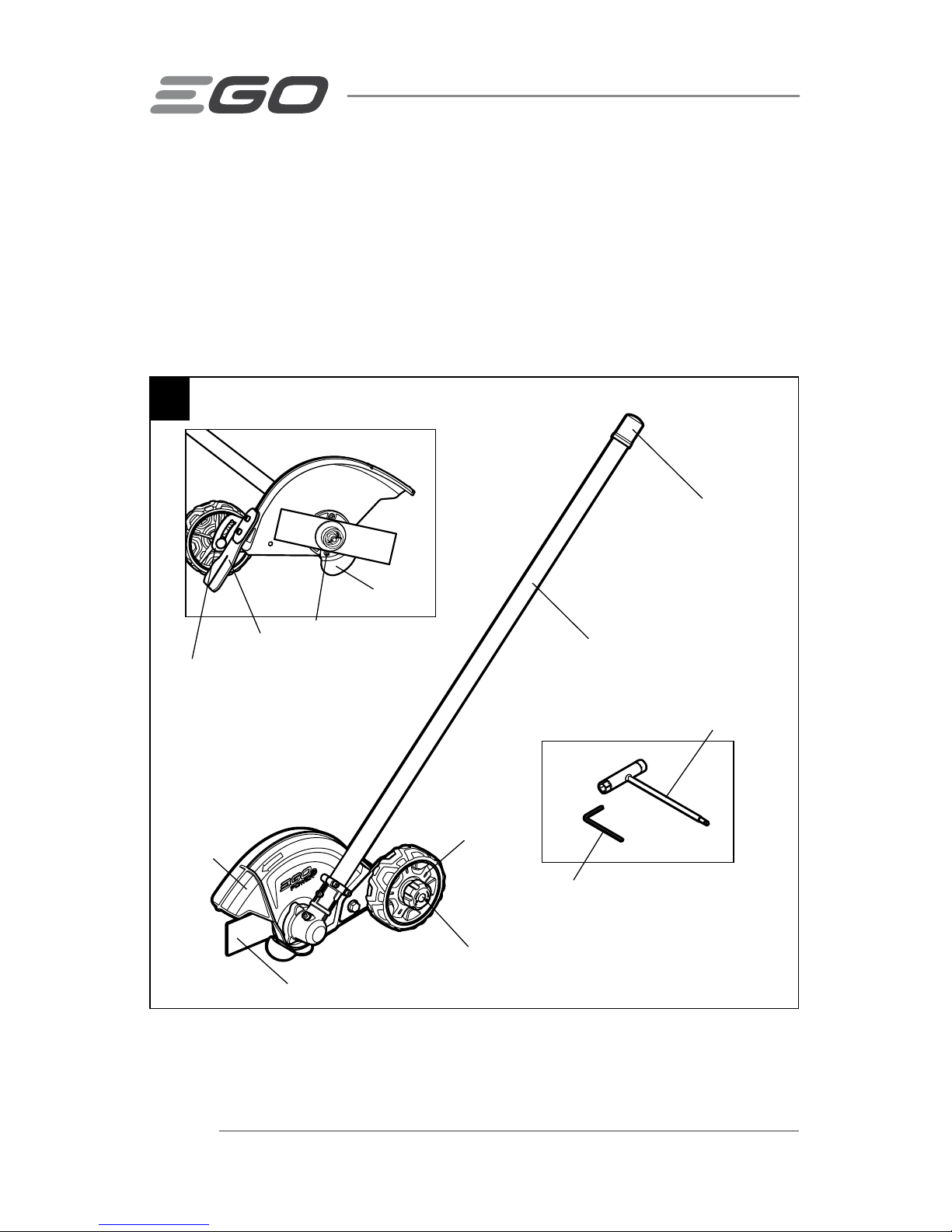
KNOW YOUR EDGER ATTACHMENT (Fig.1)
The safe use of this product requires an understanding of the information on the tool and
in this operator’s manual, as well as knowledge of the project you are attempting. Before
using this product, familiarize yourself with all operating features and safety rules.
1
Multi-function Wrench
Hex Wrench
Edger Shaft
Depth-adjusting Guide Bar
Debris Flap
Screw to lock guide plate in place
Guide Plate
End Cap
Blade
Blade Guard
Guide Wheel
Depth-adjusting Knob
Page 11

EDGER ATTACHMENT — EA0800/EA0800-FC 11
BLADE
Metal cutting blade for cutting weeds and soft green plants.
BLADE GUARD
Reduces the risk of injury from foreign objects flung backwards toward the operator by
the cutting attachment and from contact with the cutting attachment.
DEBRIS FLAP
Reduces the risk of injury from foreign objects flung back towards the operator by the
cutting blade.
DEPTH-ADJUSTING KNOB & DEPTH-ADJUSTING GUIDE BAR
Adjusts the depth of cut.
GUIDE WHEEL
Rolls on ground and keeps edger blade at preset height for required depth of cut.
GUIDE PLATE
Optional guide for cutting against pavement. (See "REMOVING THE GUIDE PLATE" if the
guide plate is not needed.)
Page 12

EDGER ATTACHMENT — EA0800/EA0800-FC12
ASSEMBLY
WARNING:
If any parts are damaged or missing, do not operate this product
until the parts are replaced. Use of this product with damaged or missing parts could
result in serious personal injury.
WARNING:
Do not attempt to modify this product or create accessories not
recommended for use with this edger. Any such alteration or modification is misuse and
could result in a hazardous condition leading to possibly serious personal injury.
WARNING:
Do not adjust the blade guard. The blade guard has been set at
the factory so that the arrow on the blade guard and the open side point away from the
operator. This ensures that cuttings and other debris are directed away from the power
tool and the operator.
UNPACKING
◾
This product requires assembly.
◾
Carefully remove the product and any accessories from the box. Make sure that
all items listed in the packing list are included.
◾
Inspect the tool carefully to make sure that no breakage or damage occurred
during shipping
◾
Do not discard the packing material until you have carefully inspected and
satisfactorily operated the tool.
◾
If any parts are damaged or missing, please return the product to the place of
purchase.
CONNECTING THE EDGER ATTACHMENT TO THE POWER HEAD
WARNING:
Never attach or adjust any attachment while the power head is
running or with the battery installed. Failure to stop the motor and remove the battery
may cause serious personal injury.
This edger attachment is designed for use with EGO Power Head PH1400/PH1400-FC.
The edger attachment connects to the power head by means of a coupler device.
1. Stop the motor and remove the battery pack.
Page 13
EDGER ATTACHMENT — EA0800/EA0800-FC 13
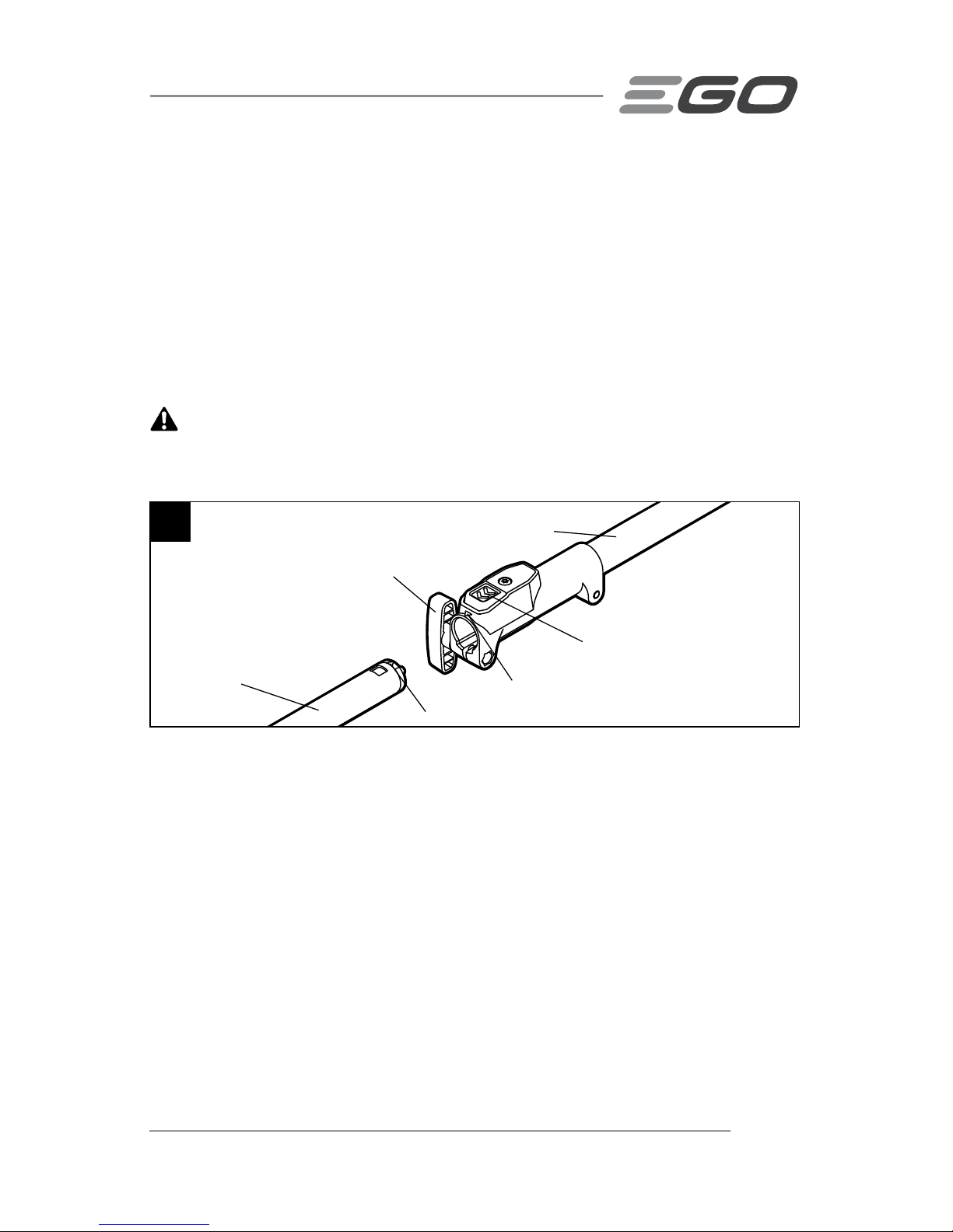
2. Loosen the wing knob.
3. Remove the end cap from the edger attachment. Align the arrow on the edger
shaft with the arrow on the coupler and push the edger shaft into the coupler until
you hear a clear “click” sound which indicates the edger shaft is mounted into
place (Fig. 2).
4. Pull the shaft of the attachment to verify it is securely locked into the coupler. If
not, rotate the edger shaft from side to side in the coupler until it snaps into place.
5. Tighten the wing knob securely.
WARNING:
Be certain the wing knob is fully tightened before operating
equipment; check it periodically for tightness during use to avoid serious personal
injury.
REMOVING THE ATTACHMENT FROM THE POWER HEAD
1. Stop the motor and remove the battery pack.
2. Loosen the wing knob.
3. Press the shaft-release button and with the button depressed, pull or twist the
attachment shaft out of the coupler.
2
Arrow on the Coupler
Arrow on the Attachment Shaft
Edger Shaft
Shaft-Release Button
Power Head Shaft
Wing Knob
Page 14

EDGER ATTACHMENT — EA0800/EA0800-FC14
OPERATION
WARNING:
Do not allow familiarity with this product to make you careless.
Remember that a careless fraction of a second is sufficient to inflict serious injury.
WARNING:
Always wear safety goggles or safety glasses with side shield
marked to comply with ANSI Z87.1. Failure to do so could result in objects being thrown
into your eyes and other possible serious injuries.
WARNING:
Do not use any attachments or accessories not recommended by the
manufacturer of this product. The use of attachments or accessories not recommended
can result in serious personal injury.
APPLICATIONS
You may use this product for the purpose listed below:
◾
Edging around walkways, curbing, flower beds and other similar areas.
Before each use check for damaged/worn parts
Check the blade, guard and front-assist handle and replace any parts that are cracked,
warped, bent, or damaged in any way.
WARNING:
To prevent serious personal injury, remove the battery pack from the
tool before servicing, cleaning, changing attachments or removing material from the
unit.
USING THE EDGER ATTACHMENT WITH POWER HEAD
WARNING:
Dress properly to reduce the risk of injury when operating this tool.
Do not wear loose clothing or jewelry. Wear eye and ear/hearing protection. Wear heavy,
long pants, boots and gloves. Do not wear short pants or sandals or go barefoot. Wear a
face mask or dust mask in dusty locations.
Page 15
EDGER ATTACHMENT — EA0800/EA0800-FC 15
WARNING:
Clear away all
obstacles and solid objects from the work
area.
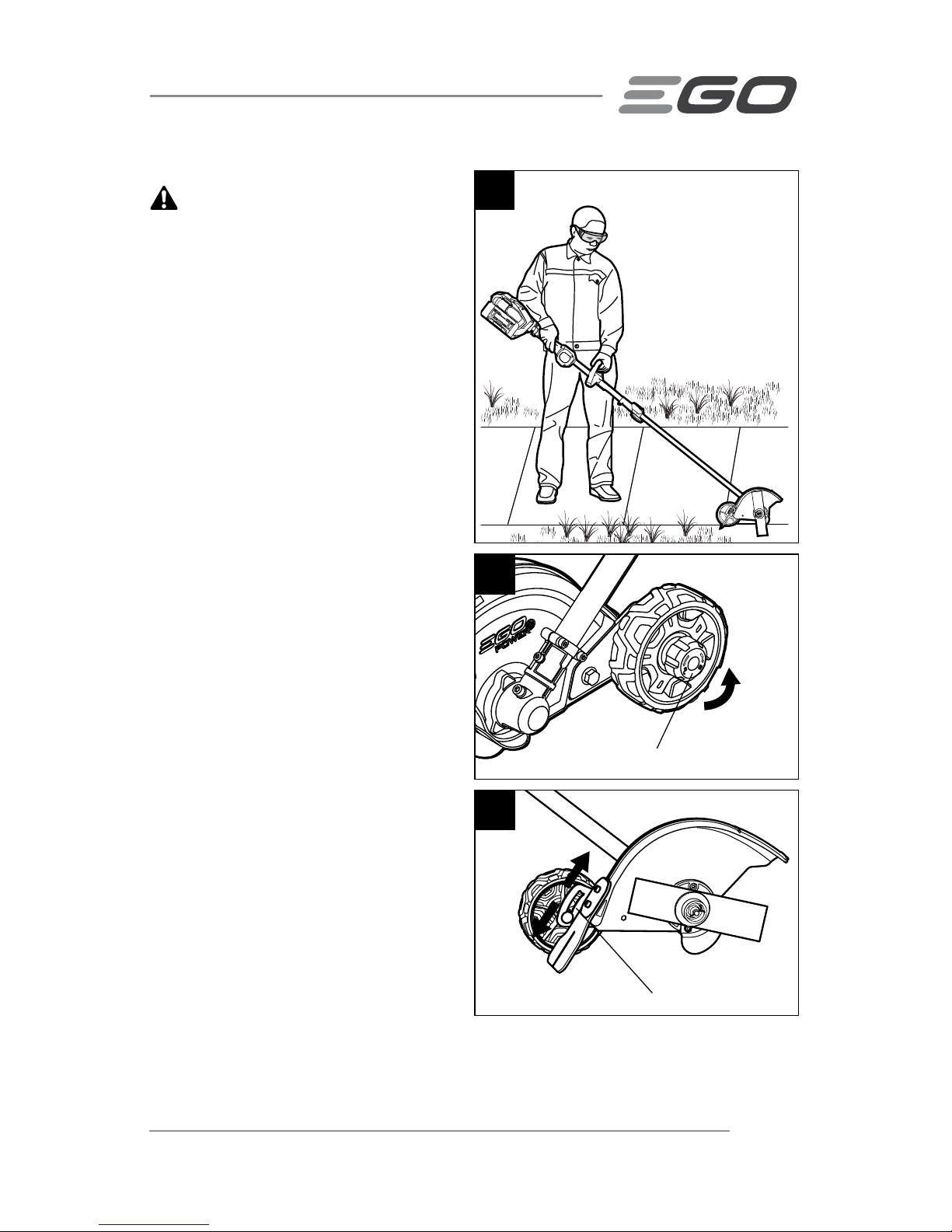
Hold the edger with your right hand on the
rear handle and your left hand on the frontassist handle. Keep a firm grip with both
hands while operating the tool. The edger
should be held at a comfortable position
with the rear handle at about hip height
(Fig. 3).
ADJUSTING DEPTH OF CUT
1. Stop the motor and remove the
battery pack.
2. Loosen the depth-adjusting knob in
the direction of the unlocking arrow
marked on the knob (Fig.4).
3. Move the guide wheel, along the
depth-adjusting guide bar, up to
increase the depth of cut or down to
decrease the depth (Fig. 5).
The depth of cut depends on the
unevenness of the ground, your height
and the way you hold the edger. Use the
following procedures:
4
Depth-adjusting Knob
5
Depth-adjusting Guide Bar
To Decrease Depth
To Increase Depth
3
Page 16
EDGER ATTACHMENT — EA0800/EA0800-FC16
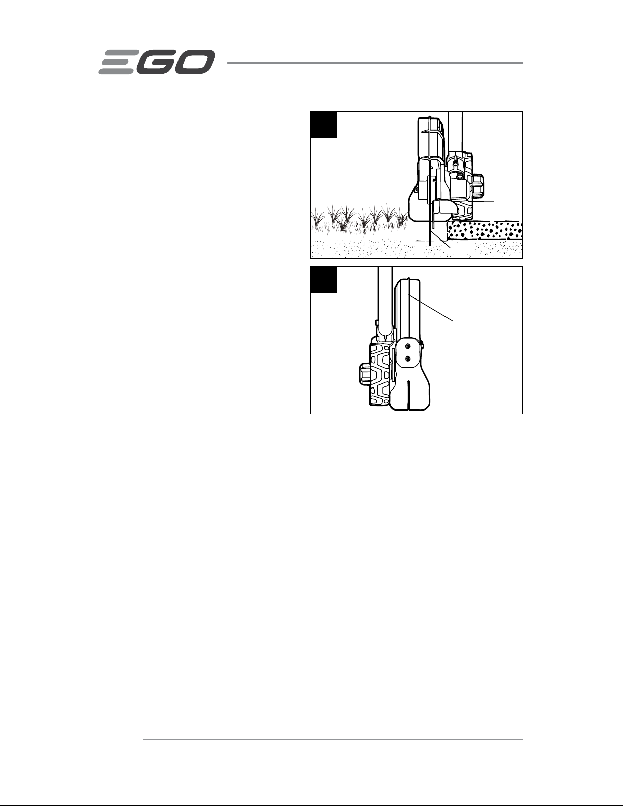
4. Adjust the guide wheel so that the
blade just touches the ground or
breaks the surface of the soil (Fig.6).
5. Tighten the depth-adjusting knob
clockwise securely, in the direction
of the locking arrow marked on the
knob
6. Standing in the normal working
position, check the depth of cut
again and correct it if necessary.
TO START/STOP THE TOOL
See "STARTING/STOPPING THE POWER
HEAD" section in the power head
PH1400/PH1400-FC operator's manual.
OPERATING TIPS
◾
Hold and guide the power head so
that the blade is vertical.
◾
Operate at no more than a normal walking pace.
◾
Cut at a steady pace. If the blade begins to bog down, you are edging too fast;
slow your pace.
◾
Do not force the blade into the ground. Light contact of the blade against the
sidewalk edge, curb, etc., is acceptable and will not damage the edger.
◾
Always walk forwards when cutting and move the edger forward. Do not pull the
edger towards you.
◾
Use the sight line to line the blade up with the edge of the bed (Fig. 7).
◾
Best appearance is obtained when grass is dry. Avoid edging in wet soil or wet
grass areas or the blade guard might clog and result in an uneven edge. If the
blade guard becomes clogged, stop the motor, remove the battery pack, and
remove debris from the blade guard.
7
Sight Line
6
Guide
Wheel
Blade
Page 17

EDGER ATTACHMENT — EA0800/EA0800-FC 17
MAINTENANCE
WARNING: When servicing, use only identical replacement parts. Use of any
other parts may create a hazard or cause product damage. To ensure safety and
reliability, all repairs should be performed by a qualified service technician.
WARNING: Battery tools do not have to be plugged into an electrical outlet;
therefore, they are always in operating condition. To prevent serious personal injury,
take extra precautions and care when performing maintenance, service or for changing
the cutting attachment or other attachments.
WARNING: To prevent serious personal injury, remove the battery pack from
the power head before servicing, cleaning, changing add-on attachments or when the
product is not in use.
GENERAL MAINTENANCE
Avoid using solvents when cleaning plastic parts. Most plastics are susceptible to
damage from various types of commercial solvents and may be damaged by their use.
Use clean cloths to remove dirt, dust, oil, grease, etc.
WARNING: Do not at any time let brake fluids, gasoline, petroleum-based
products, penetrating oils, etc., come in contact with plastic parts. Chemicals can
damage, weaken, or destroy plastic, which may result in serious personal injury.
WARNING: When cleaning the edger attachment, DO NOT immerse in water or
other liquids.
CLEAN THE UNIT
◾
After each use, remove the battery and clean the debris, clogged soils or grass on
the blade and guard with a soft brush. Wipe the edger surface with a clean cloth
moistened with a mild soap solution.
◾
Use a small brush or a small vacuum cleaner to clean the air vents on the rear
housing.
◾
Keep the air vents free of obstructions.
Page 18
EDGER ATTACHMENT — EA0800/EA0800-FC18
All edger service, other than the items listed in these maintenance instructions, should
be performed by competent edger service personnel.
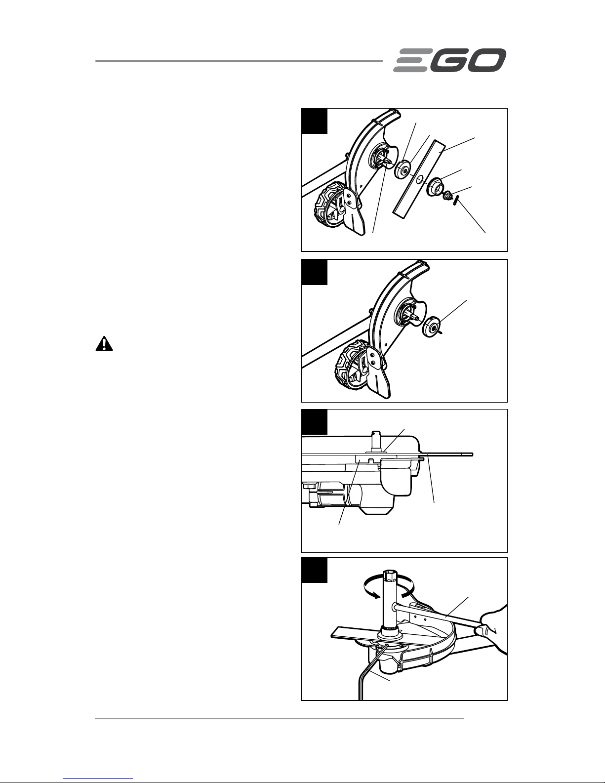
REPLACING THE BLADE
WARNING: Do not attempt to straighten or weld a bent or cracked blade. Such
a blade may break and it must be replaced. Recommend replace only with EGO edger
blade, see “Recommended Blade” section.
NOTICE: Replace the blade if its length
is no longer sufficient to maintain the
necessary ground clearance and obtain
the required depth of cut.
WARNING: Always protect
your hands by wearing heavy gloves
or wrapping the blade with rags or
other materials when performing any
maintenance on the edger blade.
Removing the blade
1. Stop the motor and remove the
battery pack.
2. Lay the edger on its back so that the
blade is facing upwards.
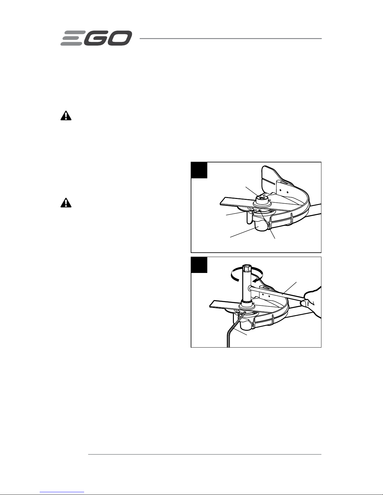
3. Wear protective gloves. Use a
needle nose pliers (not included)
to remove the cotter pin from the
motor shaft (Fig.8).
4. Rotate the blade to align the slot in the flange with the hole in the gear case
(Fig. 8).
5. Insert the hex wrench provided into the aligned holes to act as a stabilizer. Use
the multi-function wrench provided to loosen the nut CLOCKWISE (Fig.9).
8
Aligned Shaft-locking Holes
Gear Case
Inner Flange
9
Stabilizer
Multi-function
Wrench Provided
Cotter Pin
Page 19
EDGER ATTACHMENT — EA0800/EA0800-FC 19
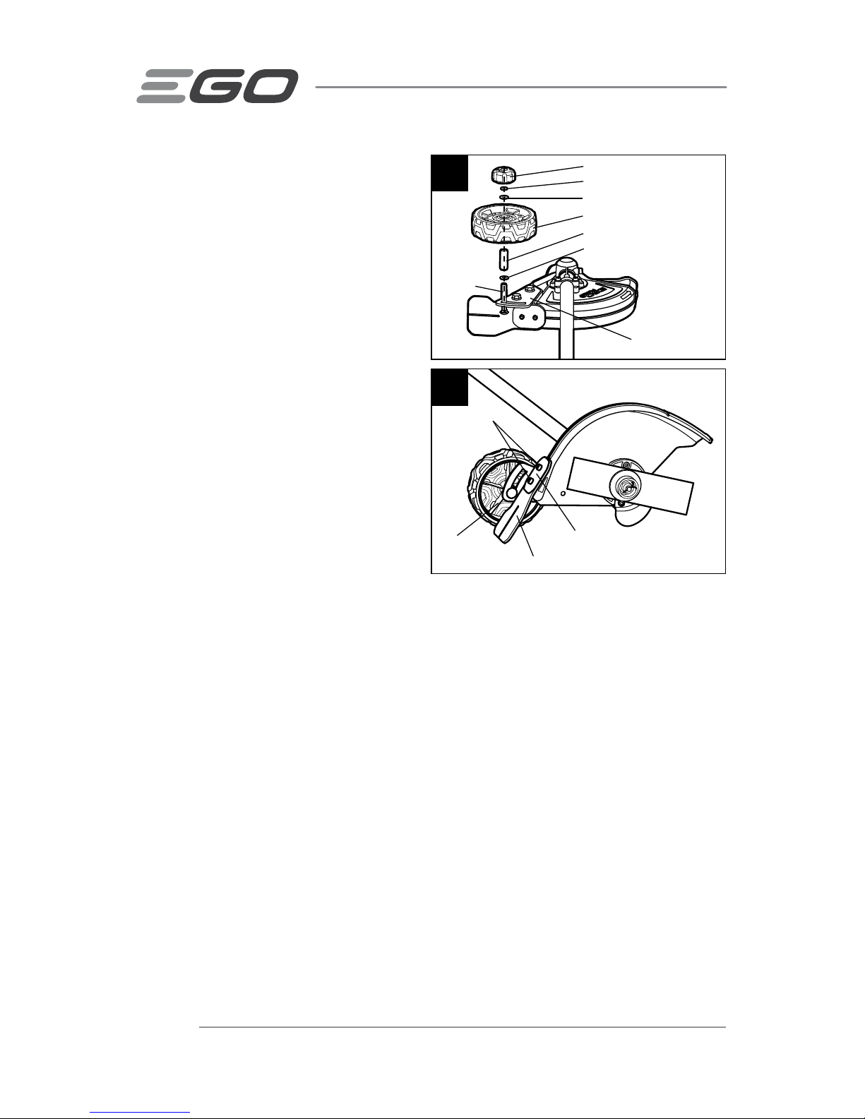
6. Remove the nut, outer flange, blade
and the inner flange from the motor
shaft (Fig. 10). Check and replace
them if they are worn.
Installing the blade
1. Position the inner flange removed in
step 6 of the “Removing the blade”
section onto the motor shaft with
the bulge of the inner flange facing
outwards (Fig.11).
2. Install the new blade onto the inner
flange.
WARNING: The bulge of the inner
flange must engage the blade’s mounting
hole (Fig.12). There should not be any
clearance between the blade and the
inner flange flat surface.
3. Mount the outer flange and the nut
onto the shaft, and pre-tighten the
nut COUNTERCLOCKWISE by hand.
4. Rotate the blade to align the slot in
the flange with the hole in the gear
case (Fig. 8).
5. Insert the hex wrench provided
into the aligned holes to act as a
stabilizer. Use the multi-function
wrench provided to tighten the nut
COUNTERCLOCKWISE securely onto
the shaft (Fig.13).
6. Insert a new cotter pin into the hole
in the motor shaft. Bent the two feet
of the pin in opposite directions with
a needle nose pliers (not included)
(Fig. 8).
13
Stabilizer
Multi-function
Wrench Provided
10
Slot in the Inner Flange
Outer Flange
Nut
Cotter Pin
Inner Flange
Blade
Motor Shaft
11
Bulge Outwards
12
Inner Flange
Blade
Bulge of the inner flange
engaging the blade
Page 20
EDGER ATTACHMENT — EA0800/EA0800-FC20
REPLACING THE GUIDE WHEEL
1. Stop the motor and remove the
battery pack.
2. Lay the edger on its back so that the
guide wheel is facing upwards.
3. Loosen the depth-adjusting knob in
the direction of the unlocking arrow
marked on the knob and removing
it.
4. Remove the spring washer, plain
washer 1, guide wheel, bushing and
plain washer 2 from the screw pole
(Fig. 14). Check and replace them if
they are worn.
5. Mount the screw pole through the
depth-adjusting guide bar first, and
then mount the plain washer 2,
bushing and new wheel, then mount
the plain washer 1, spring washer and depth-adjusting knob onto the screw pole
in the sequence shown in Fig. 14.
NOTICE: The guide wheel should be mounted with its flat ribs facing inwards (Fig. 15).
6. Lock the depth-adjusting knob in the direction of the locking arrow marked on the
knob.
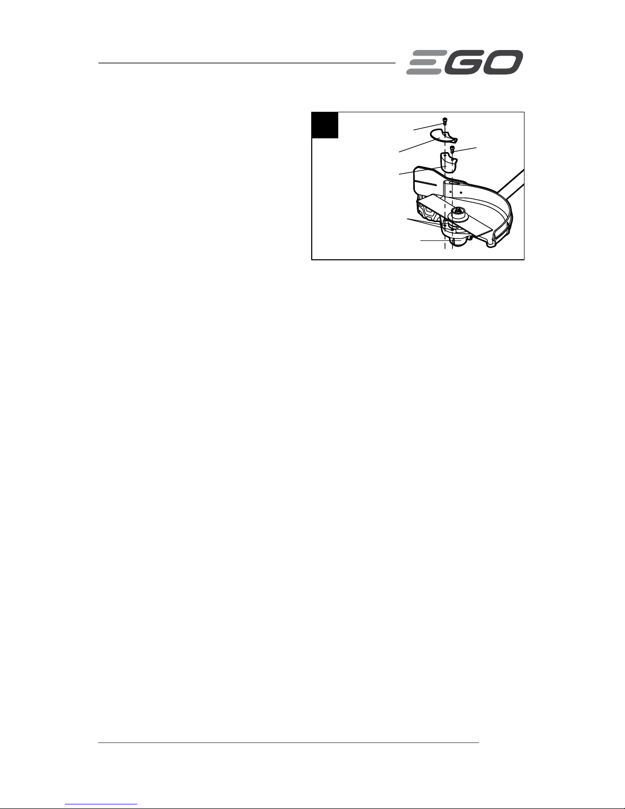
REPLACING THE DEBRIS FLAP
1. Stop the motor and remove the battery pack.
2. Use the hex wrench provided to loosen the two screws.
3. Remove the screws, fixing board and worn debris flap (Fig.15).
4. Replace with a new debris flap and lock it with the fixing board and the two
screws.
14
Depth-adjusting Knob
Spring Washer
Plain Washer 1
Guide Wheel
Bushing
Plain Washer 2
Depth-adjusting
Guide Bar
Screw Pole
15
Fixing Board
Debris Flap
Flat Rib
Screws
Page 21
EDGER ATTACHMENT — EA0800/EA0800-FC 21
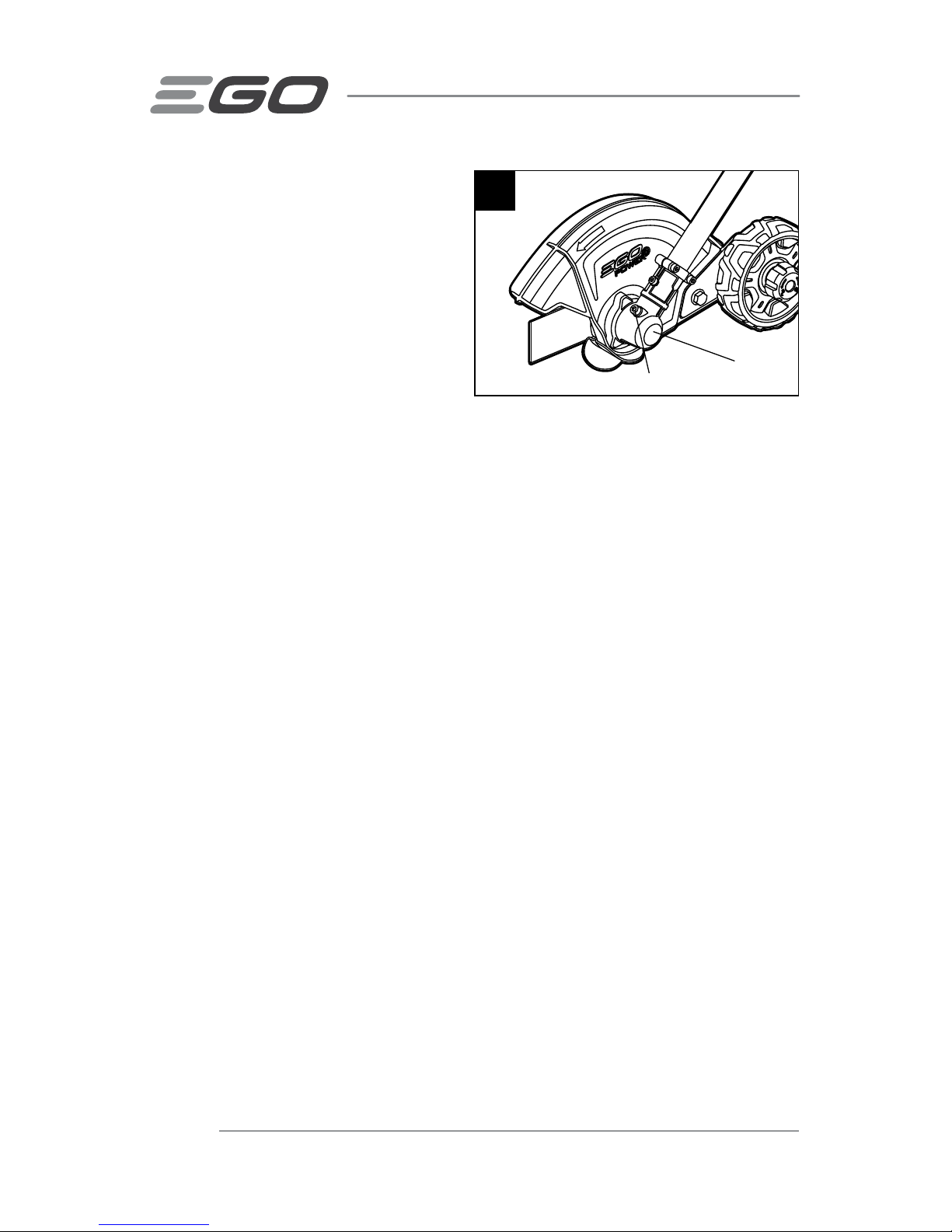
CHECKING AND REPLACING THE
ANTI-WEAR PROTECTIVE GUARD/
GUIDE PLATE (Fig. 16)
Check the anti-wear protective guard and
the guide plate for damage before starting
the power tool. The anti-wear protective
guard must be replaced as soon as the
gear case becomes visible.
NOTICE: The gear case may be seriously
damaged if you do not replace the anti-wear protective guard as soon as the gear case
is visible.
1. Stop the motor and remove the battery pack.
2. Wear protective gloves. Rotate the blade as necessary to expose the two screws.
3. Use the hex wrench provided to loosen the two screws and remove them.
NOTICE: If you just need to replace the guide plate, loosen and remove screw 1.
4. Replace the deformed or worn anti-wear protective guard and guide plate.
5. Assemble the new anti-wear protective guard and guide plate onto the gear case
and lock them with the two screws.
REMOVING THE GUIDE PLATE
If you are experienced with this type of edger, or if you find that the guide plate is a
hindrance in your edging operation, you may remove the guide plate.
1. Loosen and remove screw 1.
2. Remove the guide plate.
3. Replace and tighten screw 1.
16
Screw 1
Guide Plate
Screw 2
Anti-wear Protective
Guard
Mounting Holes
Gear Case
Page 22
EDGER ATTACHMENT — EA0800/EA0800-FC22
TRANSMISSION GEARS
LUBRICATION
The transmission gears in the gear case
need be lubricated periodically with gear
grease. Check the gear case grease level
about every 50 hours of operation by
removing the sealing screw on the side of
the case.
If no grease can be seen on the sides of
the gear, follow the steps below to fill with gear grease up to 3/4 capacity.
Do not completely fill the transmission gear case.
1. Position the edger upright so that the sealing screw is facing upwards (Fig. 17).
2. Use the multi-function wrench provided to loosen and remove the sealing screw.
3. Use a grease syringe (not included) to inject some grease into the screw hole; do
not exceed 3/4 capacity.
4. Tighten the sealing screw after injection.
STORING THE UNIT
◾
Remove the battery pack from the edger
◾
Clean the tool thoroughly before storing it.
◾
If the edger attachment is removed from the power head and stored separately:
Fit the end cap on the attachment shaft to avoid dirt getting into the coupler.
◾
Store the unit in a dry, well-ventilated area, locked-up or up high, out of the reach
of children. Do not store the unit on or adjacent to fertilizers, gasoline, or other
chemicals.
17
Sealing Screw
Gear Case
Page 23

EDGER ATTACHMENT — EA0800/EA0800-FC 23
TROUBLESHOOTING
PROBLEM CAUSE SOLUTION
Motor fails to start.
◾
The battery pack is not
attached to the power
head.
◾
Attach the battery pack to the power
head.
◾
No electrical contact
between the power head
and the battery pack.
◾
Remove the battery, check contacts
and reinstall the battery pack until it
snaps into place.
◾
The battery pack is
depleted.
◾
Charge the battery pack with EGO
chargers listed in this manual.
◾
The lock-off lever and
trigger are not depressed
simultaneously.
◾
Press down the lock-off button and
hold it, then depress the trigger to
turn on the edger.
Power head stops
during operation.
◾
The motor is overloaded.
◾
The motor will recover when the
load is removed. For continuous
working, decrease the load on the
power head.
◾
The battery pack or the
power head is too hot.
◾
Allow the battery pack or power
head to cool until the temperature
drops below 152°F (67°C).
◾
The battery pack is
disconnected from the tool.
◾
Re-install the battery pack.
◾
The battery pack is
depleted.
◾
Charge the battery pack with EGO
chargers listed in this manual.
Uneven edge.
◾
Grass or soil edged is
too wet.
◾
Avoid edging in wet soil or wet
grass.
◾
Blade guard is clogged.
◾
Stop the motor, remove the
battery pack, and remove debris
from the blade guard.
Page 24

EDGER ATTACHMENT — EA0800/EA0800-FC24
WARRANTY
EGO WARRANTY POLICY
5 year limited warranty on EGO outdoor power equipment and 3 year limited warranty
on EGO POWER+ System battery packs and chargers.
Please contact EGO Customer Service Toll-Free at 1-855-EGO-5656 any time you
have questions or warranty claims.
LIMITED SERVICE WARRANTY
FOR FIVE YEARS from the date of original retail purchase, this EGO product is warranted
against defects in material or workmanship. Defective product will receive free repair.
FOR THREE YEARS from the date of original retail purchase, the EGO POWER+ System
battery pack and charger are warranted against defects in material or workmanship.
Defective product will receive free repair.
a) This warranty applies only to the original purchaser from an authorized EGO retailer
and may not be transferred. Authorized EGO retailers are identified online at http://
egopowerplus.com/pages/warranty-policy.
b) The warranty period for any EGO product, battery pack and charger used for industrial,
professional or commercial purpose is one year.
c) The warranty period for reconditioned or refurbished products used for residential
purpose is 1 year, for industrial, professional or commercial purpose is 90 days.
d) The warranty period for routine maintenance parts, such as, but not limited to, blades,
trimmer heads, chain bars, saw chains, belts, scraper bars, blower nozzles, and
all other EGO accessories is 90 days for residential purpose, 30 days for industrial,
professional or commercial purpose. These parts are covered for 90/30 days from
manufacture defects in normal working conditions.
e) This warranty is void if the product has been used for rental purpose.
f) This warranty does not cover the damage resulting from modification, alteration or
unauthorized repair.
Page 25

EDGER ATTACHMENT — EA0800/EA0800-FC 25
g) This warranty only covers defects arising under normal usage and does not cover
any malfunction, failure or defect resulting from misuse, abuse (including overloading
of the product beyond capacity and immersion in water or other liquid), accidents,
neglect or lack of proper installation, and improper maintenance or storage.
h) This warranty does not cover normal deterioration of the exterior finish, including but
not limited to scratches, dents, paint chips, or to any corrosion or discoloring by heat,
abrasive and chemical cleaners.
HOW TO OBTAIN SERVICE
For warranty service, please contact EGO customer service toll-free at 1-855-EGO-
5656. When requesting warranty service, you must present the original dated sales
receipt. An authorized service center will be selected to repair the product according to
the stated warranty terms. When bringing your product to the authorized service center,
there may be a small deposit that will be required when dropping off your tool. This
deposit is refundable when the repair service is deemed to be covered under warranty.
ADDITIONAL LIMITATIONS
To the extent permitted by applicable law, all implied warranties, including warranties
of MERCHANTABILITY or FITNESS FOR A PARTICULAR PURPOSE, are disclaimed. Any
implied warranties, including warranties of merchantability or fitness for a particular
purpose, that cannot be disclaimed under state law are limited to five years from the
date of purchase for outdoor power equipment and three years from date of purchase
for battery pack and charger.
Chervon North America is not responsible for direct, indirect, incidental or consequential
damages.
Some states do not allow limitations on how long an implied warranty lasts and/or do
not allow the exclusion or limitation of incidental or consequential damages, so the
above limitations may not apply to you.
This warranty gives you specific legal rights, and you may also have other rights which
vary from state to state.
For customer service contact us toll-free at: 1-855-EGO-5656 or EGOPOWERPLUS.COM
EGO Customer Service, 120 Ionia Street SW / Suite 102 Grand Rapids, MI 49503
Page 26

GUIDE D'UTILISATION
COUPE-BORDURE
AMOVIBLE
NUMÉRO DE MODÈLE EA0800/EA0800-FC
EXCLUSIVEMENT POUR UTILISATION
AVEC LA TÊTE D’ALIMENTATION EGO
POWER+ PH1400/PH1400-FC
AVERTISSEMENT : Afin de réduire les risques de blessure, l’utilisateur doit lire et
comprendre le guide d’utilisation avant d’utiliser ce produit. Conservez le présent guide
afin de pouvoir le consulter ultérieurement.
Page 27

COUPE-BORDURE AMOVIBLE — EA0800/EA0800-FC 27
TABLE DES MATIÈRES
Symboles de sécurité ....................................29
Consignes de sécurité .................................30-34
Introduction ............................................34
Caractéristiques techniques ...............................35
Liste des pièces contenues dans l’emballage ..................35
Description .........................................36-37
Assemblage ......................................... 38-39
Fonctionnement ...................................... 40-42
Entretien ...........................................43-49
Dépannage ............................................50
Garantie ............................................51-52
Page 28

COUPE-BORDURE AMOVIBLE — EA0800/EA0800-FC28
LISEZ TOUTES LES INSTRUCTIONS!
LIRE ET COMPRENDRE
LE GUIDE D’UTILISATION
AVERTISSEMENT
:
La poussière créée pendant le ponçage, le sciage,
le polissage, le perçage et d’autres activités liées à la construction peut contenir
des produits chimiques reconnus par l’État de la Californie comme étant la cause
de cancers, d’anomalies congénitales et d’autres problèmes liés aux fonctions
reproductrices. Voici des exemples de ces produits chimiques :
◾
Le plomb provenant de peintures à base de plomb;
◾
La silice cristallisée contenue dans les briques, le ciment et d’autres produits de
maçonnerie;
◾
L’arsenic et le chrome contenus dans le bois d’œuvre traité avec des produits
chimiques.
Les risques liés à l’exposition à ces produits varient en fonction de la fréquence à
laquelle vous effectuez ce type de travaux. Pour réduire votre exposition à ces produits
chimiques, travaillez dans une zone bien ventilée et portez l’équipement de sécurité
approuvé, comme les masques antipoussières conçus pour ne pas laisser passer les
particules microscopiques.
Page 29

COUPE-BORDURE AMOVIBLE — EA0800/EA0800-FC 29
SYMBOLES DE SÉCURITÉ
L’objectif des symboles de sécurité est d’attirer votre attention sur les dangers
potentiels. Vous devez examiner attentivement et bien comprendre les symboles de
sécurité et les explications qui les accompagnent. Les symboles d’avertissement en
tant que tels n’éliminent pas le danger. Les consignes et les avertissements qui y sont
associés ne remplacent en aucun cas les mesures préventives adéquates.
AVERTISSEMENT
:
Avant d’utiliser cet outil, assurez-vous de lire et de
comprendre toutes les consignes de sécurité présentées dans le présent guide
d’utilisation, notamment toutes les consignes de sécurité indiquées par « DANGER »,
« AVERTISSEMENT » et « MISE EN GARDE ». Le non-respect des consignes de
sécurité ci-dessous peut occasionner une décharge électrique, un incendie ou des
blessures graves.
SIGNIFICATION DES SYMBOLES
SYMBOLE D’ALERTE DE SÉCURITÉ
:
Indique un DANGER, un
AVERTISSEMENT ou une MISE EN GARDE. Il peut être associé à d’autres symboles ou
pictogrammes.
AVERTISSEMENT
!
L’utilisation de tout outil électrique peut
entraîner la projection de corps étrangers dans les yeux et ainsi causer
des lésions oculaires graves. Avant d’utiliser un outil électrique, veillez à
toujours porter des lunettes de sécurité couvrantes ou à écrans latéraux,
ou un masque complet au besoin. Nous recommandons le port d’un
masque de sécurité panoramique par-dessus les lunettes ou de lunettes de sécurité
standard avec écrans latéraux. Portez toujours des lunettes de sécurité conformes à la
norme ANSI Z87.1.
Page 30

COUPE-BORDURE AMOVIBLE — EA0800/EA0800-FC30
CONSIGNES DE SÉCURITÉ
Vous trouverez ci-dessous les symboles de sécurité qui peuvent être présents sur
le produit, accompagnés de leur description. Vous devez lire, comprendre et suivre
toutes les instructions présentes sur l’appareil avant d’entamer son assemblage ou sa
manipulation.
Alerte de sécurité Indique un risque de blessure.
Assurez-vous
de lire et de
comprendre le
guide d’utilisation
Afin de réduire les risques de blessure,
l’utilisateur doit lire et comprendre le guide
d’utilisation avant d’utiliser ce produit.
Lunettes de
sécurité
Lorsque vous utilisez ce produit, portez toujours
des lunettes de sécurité couvrantes ou à écrans
latéraux, ou un masque complet.
Symboles de
recyclage
Le produit fonctionne à l’aide d’une pile au
lithium-ion (Li-ion). La législation locale,
provinciale ou fédérale peut interdire la mise
au rebut des piles dans les ordures ménagères.
Consultez l’organisme local de gestion des
déchets au sujet des possibilités offertes en ce
qui concerne la mise au rebut ou le recyclage.
IPX4
Indice de
protection
Protection contre les éclaboussures d’eau
V Volt Tension
mm Millimètre Longueur ou taille
cm Centimètre Longueur ou taille
in. Pouce Longueur ou taille
kg Kilogramme Poids
lb Livre Poids
Courant continu Type de courant ou caractéristique de courant
Page 31

COUPE-BORDURE AMOVIBLE — EA0800/EA0800-FC 31
CONSIGNES DE SÉCURITÉ IMPORTANTES
AVERTISSEMENT
!
Lorsque vous utilisez des appareils électriques de
jardinage, vous devez toujours suivre les consignes de sécurité élémentaires cidessous afin de réduire le risque d’incendie, de décharge électrique et de blessure.
LISEZ TOUTES LES INSTRUCTIONS
DANGER
!
Ne comptez pas sur l’isolation de l’outil pour vous protéger des
décharges électriques. Afin de réduire les risques d’électrocution, n’utilisez jamais
l’outil à proximité de fils ou de câbles susceptibles d’être sous tension.
MISE EN GARDE
!
Portez des protecteurs d’oreilles appropriés lorsque vous
utilisez l’outil. Dans certaines conditions et selon la durée d’utilisation, le bruit produit
par l’outil peut entraîner une perte auditive.
◾
Évitez les environnements dangereux. N’utilisez pas l’outil dans un endroit
mouillé ou humide.
◾
Maintenez les enfants à l’écart. Tous les visiteurs doivent se tenir à distance
de la zone de travail.
◾
Habillez-vous convenablement. Ne portez pas de vêtements amples ni
de bijoux qui peuvent s’accrocher. Ils pourraient se coincer dans les pièces
mobiles de l’outil. Le port de gants de caoutchouc et de chaussures adaptées est
recommandé lorsque vous travaillez à l’extérieur. Portez une coiffe de protection
pour retenir les cheveux longs.
◾
Portez des lunettes de sécurité. Portez toujours un masque de protection ou
un masque antipoussières lorsque l’endroit est poussiéreux.
◾
Utilisez l’outil adapté à la tâche. N’utilisez pas l’outil à des fins autres que
celles pour lesquelles il a été conçu.
◾
Ne forcez pas l’outil. Si vous l’utilisez au rythme approprié, il vous permettra de
mieux accomplir le travail avec moins de risques de blessure.
◾
Ne tendez pas les bras trop loin. Gardez une position stable et un équilibre
approprié en tout temps.
◾
Soyez vigilant. Concentrez-vous sur votre travail. Faites preuve de bon sens.
N’utilisez pas l’outil lorsque vous êtes fatigué.
◾
N’utilisez pas le coupe-bordure sous l’influence d’alcool ou de drogues.
◾
Assurez-vous que les protecteurs sont bien en place et en état de
fonctionnement.
Page 32

COUPE-BORDURE AMOVIBLE — EA0800/EA0800-FC32
◾
Gardez la lame affûtée. Remplacez une lame émoussée ou usée; ne tentez pas
de l’affûter.
◾
Gardez les mains et les pieds à distance de la zone de coupe.
◾
Ne placez aucune partie de votre corps sur la trajectoire de la lame du
coupe-bordure.
◾
Rangez les outils inutilisés à l’intérieur. Lorsque vous n’utilisez pas les outils,
rangez-les à l’intérieur, hors de portée des enfants, dans un endroit sec et en
hauteur ou dans un endroit verrouillé, et retirez le bloc-pile.
◾
Entretenez soigneusement l’outil. Gardez l’outil propre pour obtenir un
meilleur rendement et pour réduire les risques de blessure. Suivez les instructions
de graissage et de changement d’accessoires. Les poignées doivent toujours être
sèches, propres et exemptes d’huile ou de graisse.
◾
Vérifiez si des pièces sont endommagées. Avant d’utiliser l’outil, inspectez
soigneusement les protecteurs ou les autres pièces endommagés pour
déterminer s’ils peuvent fonctionner correctement et être utilisés normalement.
Vérifiez l’alignement des pièces mobiles et leur fixation ainsi que l’état et
l’assemblage des pièces, et recherchez tout autre problème pouvant nuire au
fonctionnement de l’outil. Si un protecteur ou une autre pièce est endommagé,
il doit être réparé correctement ou remplacé par un centre de service autorisé, à
moins d’indications contraires dans le présent guide.
◾
Avant chaque utilisation, dégagez l’aire de travail. Enlevez tous les objets,
comme les cailloux, les éclats de verre, les clous, les câbles ou les fils, qui
pourraient être projetés par le coupe-bordure ou qui pourraient rester coincés
dans le dispositif de coupe.
◾
Lorsque vous utilisez le coupe-bordure, tenez-le fermement par les
poignées, avec les deux mains. Refermez les doigts et les pouces autour
des poignées.
◾
Pour éviter de mettre en marche le coupe-bordure accidentellement - ne
le transportez pas en ayant le doigt sur la gâchette.
◾
Ne faites pas fonctionner le coupe-bordure dans un endroit présentant
un risque d’explosion ni en présence de gaz. Le moteur du coupe-bordure
produit habituellement des étincelles qui pourraient enflammer les vapeurs.
◾
N’utilisez pas le coupe-bordure sur des surfaces couvertes de gravier ou
à proximité de celles-ci.
Page 33

COUPE-BORDURE AMOVIBLE — EA0800/EA0800-FC 33
◾
Coupe-bordure endommagé. Si vous heurtez un objet quelconque avec le
coupe-bordure, arrêtez ce dernier immédiatement. Vérifiez s’il est endommagé et,
le cas échéant, faites-le réparer avant de le réutiliser. N’utilisez pas le coupebordure si le protecteur ou la lame est brisé.
◾
Remplacez immédiatement la lame si elle est fissurée, endommagée ou
usée, même si elle ne présente que des fissures superficielles. Ces pièces
peuvent se briser à haute vitesse et causer des blessures graves, voire mortelles.
◾
Ne rechargez pas le bloc-pile sous la pluie ni dans un endroit humide.
◾
Utilisez le produit uniquement avec les blocs-piles et les chargeurs indiqués cidessous :
BLOC-PILE CHARGEUR
BA1120, BA1120-FC, BA1400, BA1400-FC,
BA2240, BA2240-FC, BA2800, BA2800-FC,
BA4200, BA4200-FC
CH2100, CH2100-FC,
CH5500, CH5500-FC
◾
Utilisez seulement le produit avec la tête d’alimentation PH1400/PH1400-FC au
lithium-ion de 56 V.
◾
Ne jetez pas le bloc-pile au feu. Les cellules pourraient exploser. Consultez la
réglementation locale pour connaître les instructions de mise au rebut.
◾
N’ouvrez pas et n’abîmez pas le bloc-pile. L’électrolyte qu’il contient est corrosif et
peut causer des lésions oculaires ou cutanées. Il peut être toxique s’il est ingéré.
◾
Manipulez le bloc-pile avec soin pour ne pas créer un court-circuit avec
des matériaux conducteurs comme des bagues, des bracelets ou des
clés. Le bloc-pile ou le conducteur peut surchauffer et causer des brûlures.
◾
Pièces de rechange. Lorsque vous procédez à l’entretien, utilisez uniquement
des pièces de remplacement EGO identiques aux pièces d’origine. L’utilisation de
tout autre accessoire peut augmenter le risque de blessure.
◾
Les outils munis d’un bloc-pile n’ont pas besoin d’être branchés sur
une prise de courant. Par conséquent, ils sont toujours prêts à l’emploi.
Gardez à l’esprit qu’il existe des dangers potentiels même lorsque l’outil ne
fonctionne pas. Soyez prudents lorsque vous effectuez l’entretien ou des
réparations.
◾
Enlevez ou débranchez le bloc-pile avant de procéder à l’entretien ou au
nettoyage de l’outil ou d’en retirer du matériel.
◾
N’incinérez pas l’appareil, même s’il est sérieusement endommagé. Les
piles risquent d’exploser si elles sont en contact avec le feu.
Page 34

COUPE-BORDURE AMOVIBLE — EA0800/EA0800-FC34
◾
N’exposez pas un bloc-piles ou un appareil à un feu ou à une
température excessive. L’exposition au feu ou à une température supérieure à
100 °C (212 °F) peut provoquer une explosion.
◾
Ne nettoyez pas l’outil avec un jet d’eau, car de l’eau pourrait s’infiltrer
dans le moteur et les connexions électriques.
◾
S’il se produit une situation qui ne figure pas dans le présent guide,
faites preuve de prudence et de jugement. Communiquez avec le centre
de service à la clientèle d’EGO pour obtenir de l’aide.
◾
Conservez ces instructions. Consultez-les régulièrement et utilisez-les pour
expliquer le fonctionnement de l’outil à d’autres personnes qui l’utiliseraient. Si
vous prêtez cet outil à une personne, prêtez-lui également ces instructions afin de
prévenir un usage inapproprié et des blessures potentielles.
CONSERVEZ CES INSTRUCTIONS!
VOUS TROUVEREZ DES RÈGLES DE SÉCURITÉ SUPPLÉMENTAIRES
DANS LE GUIDE D’UTILISATION DE L’ACCESSOIRE APPLICABLE
INTRODUCTION
Nous vous félicitons d’avoir choisi la tête d’alimentation EGO au lithium-ion de 56 volts.
Elle a été conçue et fabriquée afin de vous offrir la meilleure fiabilité et le meilleur
rendement possible.
Si vous éprouvez un problème que vous n’arrivez pas à régler facilement, veuillez
communiquer avec le centre de service à la clientèle d’EGO au 1 855 EGO-5656.
Le présent guide contient des renseignements importants pour assembler, utiliser
et entretenir en toute sécurité votre produit. Lisez-le soigneusement avant d’utiliser
le produit. Conservez ce guide à portée de main afin de pouvoir le consulter à tout
moment.
NUMÉRO DE SÉRIE ____________________ DATE D’ACHAT _____________________
NOUS VOUS RECOMMANDONS DE NOTER LE NUMÉRO DE SÉRIE ET LA DATE D’ACHAT ET DE
LES CONSERVER EN LIEU SÛR AFIN DE POUVOIR LES CONSULTER ULTÉRIEUREMENT.
Page 35

COUPE-BORDURE AMOVIBLE — EA0800/EA0800-FC 35
CARACTÉRISTIQUES TECHNIQUES
Longueur de la lame 20,32 cm
Profondeur de coupe Jusqu’à 7,62 cm
Température de fonctionnement recommandée 0°C-40°C(32°F-104°F)
Température de stockage recommandée -20°C-70°C(-4°F-158°F)
Poids 2,26 kg (4,99 lb)
LISTE DES PIÈCES CONTENUES DANS
L’EMBALLAGE
NOM DE LA PIÈCE QUANTITÉ
Coupe-bordure amovible 1
Clé hexagonale 1
Clé multifonction 1
Goupille fendue 2
Guide d’utilisation 1
Lame recommandée
NOM DE LA PIÈCE NUMÉRO DE MODÈLE
Lame de coupe-bordure AEB0800
Page 36

COUPE-BORDURE AMOVIBLE — EA0800/EA0800-FC36
DESCRIPTION
FAMILIARISEZ-VOUS AVEC VOTRE TÊTE D’ALIMENTATION (Fig. 1)
Pour utiliser ce produit en toute sécurité, vous devez comprendre les renseignements
figurant sur le produit et dans le présent guide d’utilisation et connaître le projet que vous
entreprenez. Avant d’utiliser ce produit, familiarisez-vous avec toutes les caractéristiques
de fonctionnement et consignes de sécurité.
1
Clé multifonction
Clé hexagonale
Manche du coupe-bordure
Barre de guidage pour
réglage de la profondeur
Pare-débris
Vis servant à garder la plaque
de guidage en place
Plaque de guidage
Embout
Lame
Protège-lame
Roue de guidage
Bouton de réglage de la profondeur
Page 37

COUPE-BORDURE AMOVIBLE — EA0800/EA0800-FC 37
LAME
Lame en métal pour couper les mauvaises herbes et les plantes vertes.
PROTÈGE-LAME
Réduit les risques de blessure causée par la projection d’objets quelconques vers
l’utilisateur par le dispositif de coupe et empêche tout contact avec le dispositif de
coupe.
PARE-DÉBRIS
Réduit les risques de blessure causée par la projection d’objets quelconques vers
l’utilisateur par la lame de coupe.
BOUTON DE RÉGLAGE DE LA PROFONDEUR ET BARRE DE GUIDAGE
POUR RÉGLAGE DE LA PROFONDEUR
Permettent de régler la profondeur de coupe.
ROUE DE GUIDAGE
Roule sur le sol et maintient la lame à la hauteur préréglée pour offrir la profondeur de
coupe voulue.
PLAQUE DE GUIDAGE
Guide en option pour la coupe contre le pavé. (Consultez la section « RETRAIT DE LA
PLAQUE DE GUIDAGE » si la plaque de guidage n’est pas nécessaire.)
Page 38

COUPE-BORDURE AMOVIBLE — EA0800/EA0800-FC38
ASSEMBLAGE
AVERTISSEMENT
:
S’il y a des pièces manquantes ou endommagées, ne
tentez pas d’utiliser ce produit tant que ces pièces n’auront pas été remplacées.
L’utilisation de ce produit avec des pièces endommagées ou manquantes peut causer
des blessures graves.
AVERTISSEMENT
:
Ne tentez pas de modifier ce produit ni de créer des
accessoires dont l’utilisation n’est pas recommandée avec ce produit. Toute altération
ou modification de ce type constitue un usage inapproprié et peut engendrer une
situation dangereuse susceptible de causer des blessures graves.
AVERTISSEMENT
:
N’ajustez pas le protège-lame. Il a été réglé en usine
de façon à ce que la flèche située sur le protège-lame et le côté ouvert ne soient pas
orientés vers l’utilisateur. Les résidus de coupe et autres débris sont ainsi dirigés loin
de l’outil électrique et de l’utilisateur.
DÉBALLAGE
◾
Cet outil doit être assemblé.
◾
Retirez soigneusement l’outil et toutes les pièces de l’emballage. Assurez-vous
que toutes les pièces mentionnées sur la liste des pièces sont présentes.
◾
Inspectez soigneusement l’outil pour vérifier qu’il n’a pas été endommagé
pendant l’expédition.
◾
Ne jetez pas le matériel d’emballage avant d’avoir inspecté soigneusement l’outil
et de l’avoir fait fonctionner de manière satisfaisante.
◾
S’il y a des pièces manquantes ou endommagées, veuillez retourner l’outil à
l’endroit où vous l’avez acheté.
FIXATION DU COUPE-BORDURE SUR LA TÊTE D’ALIMENTATION
AVERTISSEMENT
:
Ne fixez ou n’ajustez jamais un accessoire pendant que
la tête d’alimentation est en marche ou que le bloc-pile est en place. Laisser le moteur
fonctionner et garder le bloc-pile en place peut entraîner de graves blessures.
Ce coupe-bordure amovible est conçu pour la tête d’alimentation EGO PH1400/
PH1400-FC.
Le coupe-bordure se fixe sur la tête d’alimentation grâce à un dispositif de raccord.
1. Arrêtez le moteur et enlevez le bloc-pile.
Page 39

COUPE-BORDURE AMOVIBLE — EA0800/EA0800-FC 39
2. Desserrez la poignée en « T ».
3. Retirez l’embout du coupe-bordure amovible. Alignez la flèche sur le manche du
coupe-bordure et la flèche sur le dispositif de raccord, puis rentrez le manche
dans le dispositif. Vous devriez entendre un « clic » qui indique que le manche du
coupe-bordure est bien en place (Fig. 2).
4. Tirez sur le manche de l’accessoire pour vous assurer qu’il est bien verrouillé
dans le dispositif de raccord. Si ce n’est pas le cas, faites tourner le manche de
gauche à droite jusqu’à ce qu’il se verrouille dans le dispositif de raccord.
5. Serrez fermement la poignée en « T ».
AVERTISSEMENT
:
Assurez-vous que la poignée en « T » est serrée
fermement avant de manipuler l’outil. Inspectez-la régulièrement pendant l’utilisation
pour vous assurer qu’elle reste serrée et pour prévenir des blessures graves.
RETRAIT DE L’ACCESSOIRE DE LA TÊTE D’ALIMENTATION
1. Arrêtez le moteur et enlevez le bloc-pile.
2. Desserrez la poignée en « T ».
3. Appuyez sur le bouton d’éjection du manche et, en le gardant enfoncé, tirez ou
tournez le manche de l’accessoire pour le dégager du dispositif de raccord.
2
Flèche sur le dispositif de raccord
Flèche sur le manche de l’accessoire
Manche du coupe-bordure
Bouton d’éjection du manche
Manche de la tête d’alimentation
Poignée en « T »
Page 40

COUPE-BORDURE AMOVIBLE — EA0800/EA0800-FC40
FONCTIONNEMENT
AVERTISSEMENT
:
Ne laissez pas votre bonne connaissance du produit vous
rendre négligent. N’oubliez pas qu’une fraction de seconde d’inattention suffit à se
blesser grièvement.
AVERTISSEMENT
:
Portez toujours des lunettes de sécurité couvrantes ou à
écrans latéraux conformes à la norme ANSI Z87.1. Sinon, vous pourriez recevoir des
débris dans les yeux et vous blesser grièvement.
AVERTISSEMENT
:
N’utilisez pas de pièces ni d’accessoires qui ne sont pas
recommandés par le fabricant de ce produit. L’utilisation de pièces ou d’accessoires
non recommandés peut causer des blessures graves.
UTILISATIONS
Vous pouvez utiliser ce produit pour les types de travaux indiqués ci-dessous :
◾
Coupe le long des allées, des bordures, des plates-bandes et autres endroits
semblables.
Avant chaque utilisation, vérifiez si des pièces sont endommagées
ou usées.
Vérifiez la lame, le protecteur et la poignée de manœuvre avant, puis remplacez toute
pièce fissurée, déformée, tordue ou endommagée.
AVERTISSEMENT
:
Pour prévenir les blessures graves, retirez le bloc-pile de
l’outil avant d’en effectuer l’entretien, de le nettoyer, de changer des accessoires ou
d’en retirer du matériel.
UTILISATION DU COUPE-BORDURE AVEC LA TÊTE D’ALIMENTATION
AVERTISSEMENT
:
Lorsque vous utilisez cet outil, habillez-vous
convenablement pour réduire les risques de blessures. Ne portez pas de vêtements ni
de bijoux qui peuvent s’accrocher. Portez des protections pour les yeux et les oreilles.
Portez un pantalon long et épais, des bottes et des gants. Ne portez pas de pantalon
court ni de sandales. N’utilisez pas l’outil lorsque vous êtes pieds nus. Portez un
masque de protection ou un masque antipoussières lorsque l’endroit est poussiéreux.
Page 41

COUPE-BORDURE AMOVIBLE — EA0800/EA0800-FC 41
4
Bouton de réglage de la profondeur
5
Barre de guidage pour
réglage de la profondeur
Pour diminuer la profondeur
Pour augmenter
la profondeur
3
AVERTISSEMENT
:
Enlevez tous
les obstacles et objets solides de l’aire de
travail.
Tenez le coupe-bordure avec la main
droite sur la poignée arrière et la main
gauche sur la poignée de manœuvre
avant. Tenez toujours fermement l’outil
avec les deux mains lorsque vous
l’utilisez. Tenez le coupe-bordure dans
une position confortable en ayant la
poignée arrière à la hauteur de votre
hanche (Fig. 3).
RÉGLAGE DE LA PROFONDEUR
DE COUPE
1. Arrêtez le moteur et enlevez le blocpile.
2. Desserrez le bouton de réglage de
la profondeur dans le sens de la
flèche de déverrouillage illustrée sur
le bouton (Fig. 4).
3. Déplacez la roue de guidage le long
de la barre de guidage. Montez-la
pour augmenter la profondeur de
coupe ou abaissez-la pour diminuer
la profondeur (Fig. 5).
La profondeur de coupe dépend de
l’inégalité du sol, de votre taille et de la
façon dont vous tenez le coupe-bordure.
Utilisez les procédures suivantes :
Page 42

COUPE-BORDURE AMOVIBLE — EA0800/EA0800-FC42
4. Ajustez la roue de guidage de façon à ce que la lame touche tout juste le sol ou
écorche la surface (Fig. 6).
5. Serrez fermement le bouton de réglage de la profondeur dans le sens de la flèche
de verrouillage illustrée sur le bouton.
6. En vous tenant debout dans la position de travail normale, vérifiez de nouveau la
profondeur de coupe et corrigez-la au besoin.
POUR DÉMARRER ET ARRÊTER L’OUTIL
Consultez la section « MISE EN MARCHE ET ARRÊT DE LA TÊTE D’ALIMENTATION »
du guide d’utilisation de la tête d’alimentation PH1400/PH1400-FC.
CONSEILS D’UTILISATION
◾
Tenez la tête d’alimentation de
façon à ce que la lame soit en
position verticale.
◾
Ne marchez pas trop vite lorsque
vous utilisez l’outil.
◾
Coupez à un rythme constant. Si la
lame commence à s’enliser, vous
coupez trop rapidement; ralentissez.
◾
Ne forcez pas pour que la lame
pénètre dans le sol. Un léger
contact de la lame avec un rebord
de trottoir, une bordure, etc., est
acceptable et n’endommagera pas
le coupe-bordure.
◾
Lorsque vous coupez, marchez
toujours vers l’avant en suivant
le coupe-bordure. Ne tirez pas le
coupe-bordure vers vous.
◾
Utilisez la ligne de visée pour aligner la lame sur le rebord de la plate-bande
(Fig. 7).
◾
Une apparence optimale est obtenue lorsque l’herbe est sèche. Évitez de couper
dans un sol mouillé ou dans l’herbe mouillée, sinon le protège-lame risque de
s’obstruer et de produire un rebord inégal. Si le protège-lame est obstrué, arrêtez
le moteur, retirez le bloc-pile, puis enlevez les débris du protège-lame.
7
Ligne de visée
6
Roue de
guidage
Lame
Page 43

COUPE-BORDURE AMOVIBLE — EA0800/EA0800-FC 43
ENTRETIEN
AVERTISSEMENT : Lorsque vous procédez à l’entretien de l’outil, utilisez
uniquement des pièces de remplacement identiques à celles d’origine. L’utilisation de
toute autre pièce peut constituer un danger ou endommager l’outil. Pour assurer la
sécurité et la fiabilité de l’outil, toutes les réparations doivent être effectuées par un
technicien qualifié.
AVERTISSEMENT : Les outils munis d’un bloc-pile n’ont pas besoin d’être
branchés sur une prise de courant. Par conséquent, ils sont toujours prêts à l’emploi.
Pour prévenir les blessures graves, prenez des précautions particulières lorsque vous
effectuez l’entretien ou des réparations, ou lorsque vous remplacez le dispositif de
coupe ou d’autres accessoires.
AVERTISSEMENT : Pour prévenir les blessures graves, retirez le bloc-pile
de la tête d’alimentation avant d’effectuer l’entretien de l’outil, de le nettoyer ou de
remplacer des accessoires, ou lorsque l’outil n’est pas utilisé.
ENTRETIEN GÉNÉRAL
Évitez d’utiliser des solvants sur les pièces en plastique. La plupart des plastiques sont
susceptibles d’être endommagés par divers types de solvants commerciaux. Utilisez un
linge propre pour enlever la saleté, la poussière, l’huile, la graisse, etc.
AVERTISSEMENT : Ne laissez en aucun temps du liquide pour freins, de
l’essence, des produits à base de pétrole, des huiles dégrippantes et autres produits
de ce genre entrer en contact avec les pièces en plastique. Les produits chimiques
peuvent endommager, affaiblir ou détruire le plastique et engendrer ainsi des risques
de blessures graves.
AVERTISSEMENT : Lors du nettoyage du coupe-bordure amovible, NE
l’immergez PAS dans l’eau ni dans un autre liquide.
NETTOYAGE DE L’APPAREIL
◾
Après chaque utilisation, retirez le bloc-pile, puis enlevez les débris, la terre
ou l’herbe de la lame et du protecteur à l’aide d’une brosse douce. Essuyez la
surface du coupe-bordure au moyen d’un linge propre et d’une solution de savon
doux.
◾
Utilisez une petite brosse ou un petit aspirateur pour nettoyer les évents
d’aération situés sur le boîtier arrière.
Page 44

COUPE-BORDURE AMOVIBLE — EA0800/EA0800-FC44
◾
Assurez-vous que les évents d’aération ne sont jamais obstrués.
Les tâches d’entretien devraient être effectuées par des réparateurs qualifiés de
coupe-bordures, à l’exception des tâches qui se retrouvent dans les présentes
instructions d’entretien.
REMPLACEMENT DE LA LAME
AVERTISSEMENT : Ne tentez pas de redresser ni de souder une lame tordue
ou fissurée. Une telle lame doit être remplacée, car elle pourrait se briser. Il est
recommandé de remplacer la lame uniquement par une lame de coupe-bordure EGO;
consultez la section « Lame recommandée ».
AVIS : Remplacez la lame si sa longueur n’est plus suffisante pour maintenir le
dégagement nécessaire au-dessus du sol et obtenir la profondeur de coupe voulue.
AVERTISSEMENT : Protégez-vous toujours les mains en portant des gants
épais ou en recouvrant la lame de chiffons ou d’autres matériaux lorsque vous
entretenez celle-ci.
Retrait de la lame
1. Arrêtez le moteur et enlevez le blocpile.
2. Déposez le coupe-bordure sur le
dos de façon à ce que la lame soit
orientée vers le haut.
3. Portez des gants de protection.
Utilisez une pince à bec effilé (non
incluse) pour retirer la goupille
d’arrêt de l’arbre du moteur (Fig. 8).
4. Tournez la lame pour aligner la fente dans le collet sur le trou du boîtier
d’engrenage (Fig. 8).
8
Trous de verrouillage alignés
Boîtier
d’engrenage
Collet intérieur
Goupille d’arrêt
Page 45

COUPE-BORDURE AMOVIBLE — EA0800/EA0800-FC 45
5. Insérez la clé hexagonale fournie
dans les trous alignés pour qu’elle
agisse comme stabilisateur. Utilisez
la clé multifonction fournie pour
desserrer l’écrou DANS LE SENS
DES AIGUILLES D’UNE MONTRE
(Fig. 9).
6. Retirez l’écrou, le collet extérieur, la
lame et le collet intérieur de l’arbre
du moteur (Fig. 10). Inspectez-les et
remplacez-les s’ils sont usés.
Installation de la lame
1. Placez le collet intérieur retiré à
l’étape 6 de la section « Retrait de
la lame » sur l’arbre du moteur,
surface bombée vers l’extérieur
(Fig. 11).
2. Installez la nouvelle lame sur le
collet intérieur.
AVERTISSEMENT :
La surface bombée du collet intérieur doit
s’enclencher dans le trou de montage de
la lame (Fig. 12). Il ne devrait pas y avoir
d’espace entre la lame et la surface plane
du collet intérieur.
3. Fixez le collet extérieur et l’écrou
sur l’arbre, puis serrez partiellement
l’écrou à la main DANS LE SENS
CONTRAIRE DES AIGUILLES D’UNE
MONTRE.
4. Faites tourner la lame pour aligner
la fente dans le collet avec le trou
du boîtier d’engrenage (Fig. 8).
9
Stabilisateur
Clé multifonction
fournie
10
Fente dans le collet intérieur
Collet extérieur
Écrou
Goupille d’arrêt
Collet intérieur
Lame
Arbre du moteur
11
Surface bombée
vers l’extérieur
12
Collet intérieur
Lame
Surface bombée du collet
intérieur enclenché dans la lame
Page 46

COUPE-BORDURE AMOVIBLE — EA0800/EA0800-FC46
5. Insérez la clé hexagonale fournie
dans les trous alignés pour qu’elle
agisse comme stabilisateur. Utilisez
la clé multifonction fournie pour
serrer fermement l’écrou sur l’arbre
DANS LE SENS CONTRAIRE DES
AIGUILLES D’UNE MONTRE (Fig. 13).
6. Insérez une nouvelle goupille d’arrêt
dans le trou de l’arbre du moteur.
Pliez les deux pieds de la goupille
dans des directions opposées avec une pince à bec effilé (non incluse) (Fig. 8).
REMPLACEMENT DE LA ROUE DE GUIDAGE
1. Arrêtez le moteur et enlevez le bloc-pile.
2. Déposez le coupe-bordure sur le dos de façon à ce que la roue de guidage soit
orientée vers le haut.
3. Desserrez le bouton de réglage de la profondeur dans le sens de la flèche de
déverrouillage illustrée sur le bouton, puis enlevez-le.
4. Retirez la rondelle à ressort, la rondelle ordinaire 1, la roue de guidage, la bague
et la rondelle ordinaire 2 de la tige de la vis (Fig. 14). Inspectez-les et remplacezles s’ils sont usés.
5. Insérez d’abord la tige de la vis dans
la barre de guidage pour réglage
de la profondeur, puis insérez la
rondelle ordinaire 2, la bague et la
nouvelle roue. Installez ensuite la
rondelle ordinaire 1, la rondelle à
ressort et le bouton de réglage de la
profondeur sur la tige de la vis dans
la séquence illustrée à la Fig. 14.
13
Stabilisateur
Clé multifonction
fournie
14
Bouton de réglage de la profondeur
Rondelle à ressort
Rondelle ordinaire
Roue de guidage
Bague
Plain WRondelle ordinaire
asher 2
Barre de
guidage pour
réglage de la
profondeur
Tige de
la vis
Page 47

COUPE-BORDURE AMOVIBLE — EA0800/EA0800-FC 47
AVIS : La roue de guidage doit être
installée avec ses nervures plates
orientées vers l’intérieur (Fig. 15).
6. Serrez le bouton de réglage de
la profondeur dans le sens de la
flèche de verrouillage illustrée sur le
bouton.
REMPLACEMENT DU PAREDÉBRIS
1. Arrêtez le moteur et enlevez le bloc-pile.
2. Utilisez la clé hexagonale fournie pour desserrer les deux vis.
3. Retirez les vis, le panneau de fixation et le pare-débris usé (Fig. 15).
4. Installez un nouveau pare-débris, puis verrouillez-le en place avec le panneau de
fixation et les deux vis.
VÉRIFICATION ET REMPLACEMENT DU PROTECTEUR ANTI-USURE ET
DE LA PLAQUE DE GUIDAGE (Fig. 16)
Vérifiez si le protecteur anti-usure et la
plaque de guidage sont endommagés
avant de mettre l’outil électrique en
marche. Le protecteur anti-usure doit être
remplacé dès que le boîtier d’engrenage
devient visible.
AVIS : Le boîtier d’engrenage peut être
gravement endommagé si vous ne
remplacez pas le protecteur anti-usure
dès que le boîtier d’engrenage est visible.
1. Arrêtez le moteur et enlevez le bloc-pile.
2. Portez des gants de protection. Faites tourner la lame au besoin pour exposer les
deux vis.
3. Utilisez la clé hexagonale fournie pour desserrer les deux vis, puis enlevez-les.
15
Panneau de fixation
Pare-débris
Nervure
plate
Vis
16
Vis 1
Plaque de guidage
Vis 2
Protecteur anti-usure
Trous de montage
Boîtier d’engrenage
Page 48

COUPE-BORDURE AMOVIBLE — EA0800/EA0800-FC48
AVIS : Si vous n’avez qu’à remplacer la plaque de guidage, desserrez et retirez la vis 1.
4. Remplacez le protecteur anti-usure et la plaque de guidage déformés ou usés.
5. Installez le nouveau protecteur anti-usure et la nouvelle plaque de guidage sur le
boîtier d’engrenage, puis fixez-les à l’aide des deux vis.
RETRAIT DE LA PLAQUE DE GUIDAGE
Si vous avez de l’expérience avec ce type de coupe-bordure, ou si vous trouvez que la
plaque de guidage nuit à votre coupe, vous pouvez enlever la plaque de guidage.
1. Desserrez et retirez la vis 1.
2. Retirez la plaque de guidage.
3. Remettez en place et serrez la vis 1.
LUBRIFICATION DES
ENGRENAGES DE TRANSMISSION
Les engrenages de transmission dans le
boîtier d’engrenage doivent être lubrifiés
périodiquement avec de la graisse
d’engrenage. Vérifiez le niveau de graisse
dans le boîtier d’engrenage toutes les 50
heures de fonctionnement en retirant la
vis d’étanchéité sur le côté du boîtier.
Si aucune graisse ne peut être vue sur les côtés de l’engrenage, suivez les étapes cidessous afin de remplir le boîtier de graisse d’engrenage aux 3/4 de sa capacité.
Ne remplissez pas complètement le boîtier d’engrenage de transmission.
1. Placez le coupe-bordure debout de façon à ce que la vis d’étanchéité soit orientée
vers le haut (Fig. 17).
2. Utilisez la clé multifonction fournie pour desserrer et retirer la vis d’étanchéité.
3. Utilisez une seringue contenant de la graisse (non incluse) pour injecter de la
graisse dans le trou de la vis; ne dépassez pas les 3/4 de la capacité du boîtier.
4. Serrez la vis d’étanchéité après l’injection.
17
Sealing Screw
Gear Case
Page 49

COUPE-BORDURE AMOVIBLE — EA0800/EA0800-FC 49
RANGEMENT DE L’APPAREIL
◾
Retirez le bloc-pile du coupe-bordure.
◾
Nettoyez complètement l’outil avant de le ranger.
◾
Si le coupe-bordure amovible est retiré de la tête d’alimentation et rangé
séparément : Placez l’embout sur le manche de l’accessoire pour éviter que de la
saleté s’introduise dans le dispositif de raccord.
◾
Rangez l’appareil dans un endroit sec, bien aéré et surélevé ou verrouillé, hors
de portée des enfants. Ne rangez pas l’appareil sur des engrais, de l’essence ou
d’autres produits chimiques, ni à proximité de ces produits.
Page 50

COUPE-BORDURE AMOVIBLE — EA0800/EA0800-FC50
DÉPANNAGE
PROBLÈME CAUSE SOLUTION
Le moteur ne
démarre pas.
◾
Le bloc-pile n’est pas
installé dans la tête
d’alimentation.
◾
Installez le bloc-pile dans la tête
d’alimentation.
◾
Il n’y a pas de contact
électrique entre la tête
d’alimentation et le blocpile.
◾
Retirez le bloc-pile, vérifiez les
contacts électriques, puis réinstallez
le bloc-pile jusqu’à ce qu’il
s’enclenche.
◾
Le bloc-pile est déchargé.
◾
Chargez le bloc-pile avec les
chargeurs EGO indiqués dans le
présent guide.
◾
Le levier de blocage et
la gâchette ne sont pas
enclenchés simultanément.
◾
Pour mettre en marche le
coupe-bordure, maintenez le bouton
de blocage enfoncé lorsque vous
appuyez sur la gâchette.
La tête
d’alimentation
s’arrête pendant
l’utilisation.
◾
Le moteur est surchargé.
◾
Le moteur fonctionnera de nouveau
sans problème lorsque la cause de
la surcharge sera éliminée. Pour
assurer un fonctionnement continu,
réduisez la charge sur la tête
d’alimentation.
◾
Le bloc-pile ou la tête
d’alimentation est trop
chaud.
◾
Laissez le bloc-pile ou la tête
d’alimentation refroidir jusqu’à une
température inférieure à 67 °C
(152 °F).
◾
Le bloc-pile est débranché
de l’outil.
◾
Réinstallez le bloc-pile.
◾
Le bloc-pile est déchargé.
◾
Chargez le bloc-pile avec les
chargeurs EGO indiqués dans le
présent guide.
Le rebord est
inégal.
◾
L’herbe ou la terre est
trop mouillée.
◾
Évitez de couper dans un sol
mouillé ou dans l’herbe mouillée.
◾
Le protège-lame est
obstrué.
◾
Arrêtez le moteur, retirez le
bloc-pile, puis enlevez les débris
du protège-lame.
Page 51

COUPE-BORDURE AMOVIBLE — EA0800/EA0800-FC 51
GARANTIE
POLITIQUE D’EGO EN MATIÈRE DE GARANTIE
Une garantie limitée de 5 ans est offerte pour l’équipement électrique d’extérieur EGO
et une garantie limitée de 3 ans est offerte pour les chargeurs et les blocs-piles EGO
POWER+.
Veuillez communiquer avec le service à la clientèle d’EGO au 1 855 EGO-5656
(numéro sans frais) pour toute question sur les réclamations au titre de la garantie.
GARANTIE LIMITÉE
À compter de la date d’achat originale, ce produit EGO est garanti PENDANT CINQ
ANS contre les défauts de matériaux et de fabrication. Les produits défectueux seront
réparés gratuitement.
À compter de la date d’achat originale, le chargeur et le bloc-pile EGO POWER+ sont
garantis PENDANT TROIS ANS contre les défauts de matériaux et de fabrication. Les
produits défectueux seront réparés gratuitement.
a) Cette garantie s’applique uniquement à l’acheteur initial s’étant procuré le produit
chez un détaillant EGO autorisé et est non transférable. La liste des détaillants EGO
autorisés est publiée en ligne sur le site http://egopowerplus.com/pages/warrantypolicy.
b) La période de garantie pour le bloc-pile, le chargeur ou tout produit EGO utilisés à des
fins industrielles, professionnelles ou commerciales est de un an.
c) La période de garantie pour les produits remis en état ou remis à neuf utilisés à
des fins résidentielles est de 1 an, et de 90 jours lorsqu’ils sont utilisés à des fins
industrielles, professionnelles ou commerciales.
d) La période de garantie pour les pièces d’entretien régulier, y compris, mais sans s’y
limiter, les lames, les têtes de coupe-bordure, les guides-chaînes, les chaînes de scie,
les courroies, les barres de raclage, les buses de souffleur, ainsi que tous les autres
accessoires EGO, est de 90 jours lorsqu’elles sont utilisées à des fins résidentielles
et de 30 jours lorsqu’elles sont utilisées à des fins industrielles, professionnelles ou
commerciales. Ces pièces sont couvertes contre les défauts de fabrication pour une
période de 90 jours ou de 30 jours si elles sont utilisées dans des conditions de travail
normales.
e) Cette garantie n’est pas valide si le produit a été utilisé à des fins de location.
Page 52

COUPE-BORDURE AMOVIBLE — EA0800/EA0800-FC52
f) La présente garantie ne couvre pas les dommages résultant d’une modification, d’une
altération ou d’une réparation non autorisée.
g) Cette garantie couvre uniquement les défauts survenant dans des conditions normales
d’utilisation et ne couvre aucun dysfonctionnement ou défaut ni aucune défaillance
découlant d’un usage inapproprié ou abusif (notamment la surcharge du produit et
son immersion dans l’eau ou dans tout autre liquide), d’un accident, d’une négligence,
d’une installation inadéquate et de tout entretien ou entreposage inadéquat.
h) Cette garantie ne couvre pas la détérioration normale du fini extérieur, notamment les
rayures, les bosses, les craquelures de la peinture, ni toute corrosion ou décoloration
résultant de la chaleur, de produits abrasifs et de nettoyants chimiques.
RÉCLAMATION AU TITRE DE LA GARANTIE
Pour faire une réclamation au titre de la garantie, veuillez communiquer avec le service
à la clientèle d’EGO au 1 855 EGO-5656 (numéro sans frais). Lorsque vous faites une
réclamation au titre de la garantie, vous devez présenter le reçu de vente original. Un
centre de service autorisé sera sélectionné pour la réparation du produit conformément
aux conditions de garantie prescrites. Il se peut qu’un petit dépôt soit exigé lorsque
vous laissez votre outil dans un centre de service autorisé. Ce dépôt est remboursable
lorsque le service de réparation est considéré comme étant couvert par la garantie.
RESTRICTIONS SUPPLÉMENTAIRES
Dans les limites prescrites par la législation locale, toutes les garanties implicites,
notamment les garanties de QUALITÉ MARCHANDE ou d’ADÉQUATION POUR UN USAGE
PARTICULIER, sont non valides. Toute garantie implicite, notamment les garanties de
qualité marchande ou d’adéquation pour un usage particulier, qui ne peut être déclinée
en vertu de la législation provinciale est limitée à cinq (5) ans à compter de la date
d’achat pour l’équipement électrique d’extérieur et à trois (3) ans à compter de la date
d’achat pour les chargeurs et blocs-piles.
Chervon North America n’est pas responsable des dommages accessoires, consécutifs,
indirects ou directs.
Certaines provinces et certains États n’autorisent pas les restrictions de durée de
garantie implicite, ou l’exclusion ou la restriction des dommages accessoires ou
consécutifs; c’est pourquoi les restrictions ci-dessus peuvent ne pas s’appliquer à votre
cas.
Page 53

MANUAL DEL USUARIO
ACCESORIO
PARA BORDEADORA
MODELO NÚMERO EA0800/EA0800-FC
EXCLUSIVAMENTE PARA USO CON EL
CABEZAL MOTOR POWER+ PH1400/PH1400-FC
ADVERTENCIA: para reducir el riesgo de lesiones, el usuario debe leer y comprender
el Manual del usuario antes de usar este producto. Guarde estas instrucciones para
consultarlas en el futuro.
Page 54

ACCESORIO PARA BORDEADORA — EA0800/EA0800-FC
54
ÍNDICE
Símbolos de seguridad ...................................56
Instrucciones de seguridad .............................57-61
Introducción ............................................61
Especificaciones ........................................61
Lista de empaque .......................................62
Descripción ......................................... 63-64
Ensamblaje .........................................65-66
Funcionamiento ...................................... 67-69
Mantenimiento .......................................70-75
Solución de problemas ...................................76
Garantía ............................................77-78
Page 55

ACCESORIO PARA BORDEADORA — EA0800/EA0800-FC
55
¡LEA TODAS LAS INSTRUCCIONES!
LEA Y COMPRENDA EL
MANUAL DEL USUARIO
ADVERTENCIA
:
Parte del polvo producto del lijado, aserrado, esmerilado,
taladrado y otras actividades de construcción, contiene sustancias químicas que el
estado de California reconoce como causantes de cáncer, defectos congénitos u otros
daños al sistema reproductor. Algunos ejemplos de estas sustancias químicas son los
siguientes:
◾
Plomo de pinturas a base de plomo;
◾
Sílice cristalina de ladrillos, cemento y otros productos de mampostería; y
◾
Arsénico y cromo de madera tratada químicamente.
El riesgo de sufrir estas exposiciones varía según la frecuencia con que realice este
tipo de trabajo. Medidas para reducir la exposición a estos químicos: trabaje en un
lugar bien ventilado y con equipos de seguridad aprobados, como las mascarillas
antipolvo que están diseñadas especialmente para filtrar partículas microscópicas.
Page 56

ACCESORIO PARA BORDEADORA — EA0800/EA0800-FC
56
SÍMBOLOS DE SEGURIDAD
El propósito de los símbolos de seguridad es alertarlo sobre posibles peligros. Los
símbolos de seguridad y sus explicaciones merecen una atención y comprensión
minuciosas. Las advertencias de los símbolos, por sí mismas, no eliminan los peligros.
Las instrucciones y las advertencias no sustituyen las medidas de prevención de
accidentes que correspondan.
ADVERTENCIA
:
Antes de utilizar esta herramienta, asegúrese de leer y
comprender todas las instrucciones de seguridad en este Manual del usuario, incluidos
todos los símbolos de alerta de seguridad como “PELIGRO”, “ADVERTENCIA” y
“PRECAUCIÓN”. No seguir todas las instrucciones que se indican a continuación podría
resultar en descargas eléctricas, incendios y/o lesiones personales graves.
SIGNIFICADO DE LOS SÍMBOLOS
SÍMBOLO DE ALERTA DE SEGURIDAD
:
Indica PELIGRO, ADVERTENCIA O
PRECAUCIÓN. Puede aparecer junto con otros símbolos o pictografías.
¡ADVERTENCIA
!
La utilización de herramientas eléctricas puede
hacer que algunos objetos extraños golpeen los ojos y cause heridas
graves. Antes de comenzar a operar una herramienta eléctrica, use
siempre gafas protectoras o gafas de seguridad con blindaje lateral y un
protector facial si es necesario. Le recomendamos usar una máscara de
seguridad de visión amplia sobre anteojos o gafas de seguridad estándar con
protección lateral. Use siempre lentes de protección con la marca de cumplimiento de
la norma ANSI Z87.1.
Page 57

ACCESORIO PARA BORDEADORA — EA0800/EA0800-FC
57
INSTRUCCIONES DE SEGURIDAD
Esta página muestra y describe los símbolos de seguridad que pueden aparecer en
este producto. Lea, comprenda y siga todas las instrucciones de la máquina antes de
ensamblarla y utilizarla.
Alerta de
seguridad
Indica un peligro potencial de producir lesiones.
Lea y comprenda
el Manual del
usuario
Para reducir el riesgo de lesiones, el usuario debe
leer y comprender el Manual del usuario antes de
usar este producto.
Lentes de
protección
Use siempre gafas de seguridad o anteojos con
protección lateral y un protector facial al operar
este producto.
Símbolos de
reciclaje
Este producto usa baterías de iones de litio. Es
posible que las leyes municipales, provinciales
o nacionales prohíban desechar las baterías con
los residuos comunes. Consulte a la autoridad
local en materia de residuos sobre las opciones
de eliminación y reciclaje disponibles.
IPX4
Grado de
protección de
admisión
Protección contra salpicaduras de agua
V Voltio Voltaje
mm Milímetro Longitud o tamaño
cm Centímetro Longitud o tamaño
in. Pulgada Longitud o tamaño
kg Kilogramo Peso
lb Libra Peso
Corriente
continua
Tipo o característica de la corriente
Page 58

ACCESORIO PARA BORDEADORA — EA0800/EA0800-FC
58
INSTRUCCIONES IMPORTANTES DE SEGURIDAD
ADVERTENCIA
:
Al usar artefactos eléctricos de jardinería, las precauciones
básicas de seguridad deberán respetarse para reducir el riesgo de incendios,
descargas eléctricas y lesiones personales; entre ellas se incluyen:
LEA TODAS LAS INSTRUCCIONES
¡PELIGRO!
No dependa del aislamiento de la herramienta para evitar las
descargas eléctricas. Para reducir el riesgo de electrocución, nunca opere la
herramienta en las cercanías de cables que conducen corriente eléctrica.
¡PRECAUCIÓN!
Use protección auditiva personal adecuada durante la
manipulación. Bajo algunas condiciones y periodos de uso, el ruido de este producto
podría contribuir a la pérdida de la audición.
◾
Evite entornos peligrosos – no use la herramienta en lugares húmedos o
mojados.
◾
Mantenga a los niños alejados – todos los visitantes deben mantenerse
alejados del área de trabajo.
◾
Vístase de manera adecuada – no use ropa holgada ni joyas. Estas pueden
quedar atascadas en las piezas móviles. Se recomienda usar guantes y calzado
de goma para trabajar en exteriores. Use protección para el cabello a fin de
contener el cabello largo.
◾
Use gafas de seguridad – use siempre una máscara o mascarilla antipolvo si
trabajará en una zona con mucho polvo.
◾
Use la herramienta adecuada – no use la herramienta para ninguna otra tarea
que no sea la prevista.
◾
No fuerce el aparato – esta máquina funcionará mejor y con menos
probabilidades de producir lesiones si se usa al ritmo para el cual se diseñó.
◾
No se extralimite – mantenga el punto de apoyo y el equilibrio adecuado en
todo momento.
◾
Manténgase alerta – concéntrese en lo que hace. Use el sentido común. No
opere el aparato si está cansado.
◾
No opere la bordeadora bajo la influencia de drogas o alcohol.
◾
Mantenga las protecciones en su lugar y en buen estado.
◾
Mantenga las cuchillas afiladas. Reemplace la cuchilla si no tiene filo o está
desgastada; no intente afilarla.
Page 59

ACCESORIO PARA BORDEADORA — EA0800/EA0800-FC
59
◾
Mantenga las manos y los pies alejados del área de corte.
◾
Nunca se pare ni exponga ninguna parte de su cuerpo en línea con la
trayectoria de la cuchilla de la bordeadora.
◾
Guarde los aparatos en el interior - cuando no esté en uso, los aparatos
deben guardarse en interiores, en un lugar seco y alto o bajo llave, sin el paquete
de baterías y fuera del alcance de los niños.
◾
Cuide su aparato - mantenga el aparato limpio para obtener mejores resultados
y reducir el riesgo de lesiones. Siga las instrucciones para lubricar y cambiar los
accesorios. Mantenga las manijas limpias, secas y libres de aceite y grasa.
◾
Revise las piezas dañadas - antes de continuar con la operación del producto,
se deben revisar con cuidado las protecciones u otras piezas dañadas a fin
de determinar si funcionan correctamente y cumplen su función específica.
Compruebe la alineación de las piezas móviles, que las piezas no estén dobladas
o rotas, que el montaje sea el correcto y cualquier otra condición que pueda
afectar el funcionamiento. Las protecciones u otras piezas dañadas deben
repararse de manera adecuada o cambiarse en un centro de servicio autorizado,
a menos que se indique lo contrario en este manual.
◾
Limpie el área que cortará antes de cada uso. Retire todos los objetos como
piedras, vidrios rotos, clavos, alambres o cordeles que puedan salir despedidos o
atascarse en los accesorios de corte.
◾
Sostenga la bordeadora con firmeza y mantenga ambas manos en las
manijas durante la operación. Coloque sus dedos y pulgares alrededor de
las empuñadoras.
◾
Evite los arranques accidentales - no transporte la bordeadora con el dedo en
la perilla de encendido.
◾
No opere la bordeadora en entornos gaseosos o explosivos. Los motores
de estos aparatos comúnmente producen chispas, las que pueden encender los
vapores.
◾
No utilice la bordeadora en o cerca de superficies con gravilla.
◾
Daños a la bordeadora - si golpea un objeto extraño con la bordeadora o si
esta se atasca, detenga la herramienta de inmediato, revise si hay daños y,
de haberlos, repárelos antes volver a operar la herramienta. No la opere si las
protecciones o la cuchilla están dañadas.
◾
Reemplace la cuchilla si está agrietada, dañada o gastada de inmediato,
aunque solo se trate de grietas superficiales. Dichos accesorios podrían
desprenderse a alta velocidad y provocar lesiones graves o fatales.
Page 60

ACCESORIO PARA BORDEADORA — EA0800/EA0800-FC
60
◾
No cargue el paquete de baterías bajo la lluvia o en lugares húmedos.
◾
Use solamente con el paquete de baterías y el cargador que se indican a
continuación:
PAQUETES DE BATERÍAS CARGADOR
BA1120, BA1120-FC, BA1400, BA1400-FC,
BA2240, BA2240-FC, BA2800, BA2800-FC,
BA4200, BA4200-FC
CH2100, CH2100-FC,
CH5500, CH5500-FC
◾
Use solo con el cabezal motor PH1400/PH1400-FC de iones de litio de 56 V.
◾
No arroje las baterías al fuego. Las células pueden explotar. Consulte los
códigos locales para conocer las posibles instrucciones de desecho especiales.
◾
No abra ni rompa la batería. Los electrolitos liberados son corrosivos y pueden
causar daños en los ojos o la piel. Si se tragan pueden ser tóxicos.
◾
Manipule las baterías con cuidado para no acortar su vida útil con
materiales conductores como anillos, brazaletes y llaves. La batería o el
conductor podrían sobrecalentarse y producir quemaduras.
◾
Piezas de repuesto - al realizar mantenimiento, utilice solo piezas de repuesto
EGO idénticas. El uso de cualquier otro accesorio puede aumentar el riesgo de
lesiones.
◾
Las herramientas a batería no necesitan estar conectadas a un enchufe,
por lo tanto siempre se encuentran en condiciones de funcionar.
Conozca los peligros posibles que existen aun cuando la herramienta no esté en
funcionamiento. Tenga cuidado al realizarle mantenimiento o repararla.
◾
Retire o desconecte el paquete de baterías antes de hacer el
mantenimiento, limpiar o retirar material del producto.
◾
No incinere el electrodoméstico incluso si está muy dañado. Las baterías
pueden explotar en un incendio.
◾
No lave el producto con una manguera; evite que el motor y las
conexiones eléctricas se mojen.
◾
No exponga el paquete de baterías ni el electrodoméstico al fuego o
a una temperatura excesiva. La exposición al fuego o a temperaturas por
encima de los 100 °C (212°F) podría causar una explosión.
◾
Si se presentan situaciones que no están previstas en este manual,
tenga cuidado y use el sentido común. Póngase en contacto con el
Centro de Servicio al Cliente de EGO para recibir ayuda.
Page 61

ACCESORIO PARA BORDEADORA — EA0800/EA0800-FC
61
◾
Guarde estas instrucciones. Consúltelas con frecuencia y úselas para dar
instrucciones a otras personas que puedan usar esta herramienta. Si le presta
esta herramienta a alguien, préstele también estas instrucciones para evitar el
mal uso del producto y posibles lesiones.
GUARDE ESTAS INSTRUCCIONES.
EN EL MANUAL DEL USUARIO CORRESPONDIENTE AL ACCESORIO
SE PUEDEN ENCONTRAR NORMAS ESPECÍFICAS DE SEGURIDAD
ADICIONALES.
INTRODUCCIÓN
Felicitaciones por elegir el cabezal motor EGO de iones de litio de 56 voltios. Este
está pensado, diseñado y fabricado para brindarle el mejor rendimiento y la mejor
confiabilidad posibles.
En caso de que tuviera algún problema que no pudiera resolver fácilmente, póngase en
contacto con el Centro de Servicio al Cliente de EGO al 1-855-EGO-5656.
NÚMERO DE SERIE ____________________ FECHA DE COMPRA __________________
DEBE ANOTAR EL NÚMERO DE SERIE Y LA FECHA DE COMPRA Y CONSERVARLOS EN UN
LUGAR SEGURO PARA CONSULTARLOS EN EL FUTURO.
ESPECIFICACIONES
Largo de la cuchilla 8" (20,32 cm)
Profundidad de corte hasta 3" (7,62 cm)
Temperatura de funcionamiento recomendada 0°C-40°C(32°F-104°F)
Temperatura de almacenamiento recomendada -20°C-70°C(-4°F-158°F)
Peso 4,99 lb (2,26 kg)
Page 62

ACCESORIO PARA BORDEADORA — EA0800/EA0800-FC
62
LISTA DE EMPAQUE
NOMBRE DE LA PIEZA CANTIDAD
Accesorio para bordeadora 1
Llave hexagonal 1
Llave multiuso 1
Chaveta 2
Manual del usuario 1
Cuchilla recomendada
NOMBRE DE LA PIEZA NÚMERO DE MODELO
Cuchilla para bordeadora AEB0800
Page 63

ACCESORIO PARA BORDEADORA — EA0800/EA0800-FC
63
DESCRIPCIÓN
CONOZCA EL CABEZAL MOTOR (Fig. 1)
El uso seguro de este producto requiere que se comprenda la información que figura
en la herramienta y en este manual del usuario, además del conocimiento del proyecto
que desea llevar a cabo. Antes de usar este producto, familiarícese con todas las
características operativas y reglas de seguridad.
1
Llave multiuso
Llave hexagonal
Mango de la bordeadora
Barra guía
para ajuste de
profundidad
Cubierta de
desechos
Atornille para asegurar
la placa guía en su lugar.
Placa guía
Tapa del extremo
Cuchilla
Protector de
la cuchilla
Rueda guía
Perilla para ajuste
de profundidad
Page 64

ACCESORIO PARA BORDEADORA — EA0800/EA0800-FC
64
CUCHILLA
Cuchilla de corte de metal para cortar maleza y plantas blandas.
PROTECTOR DE LA CUCHILLA
Reduce el riesgo de lesiones provocadas por objetos extraños que se disparan hacia el
operador desde el accesorio de corte y por el contacto con el accesorio de corte.
CUBIERTA DE DESECHOS
Reduce el riesgo de lesiones por objetos extraños expulsados en dirección al operador
por la cuchilla de corte.
PERILLA PARA AJUSTE DE PROFUNDIDAD Y BARRA GUÍA PARA
AJUSTE DE PROFUNDIDAD
Ajusta la profundidad de corte.
RUEDA GUÍA
Rueda por el suelo y mantiene la cuchilla de la bodeadora a la altura programada para
la profundidad de corte necesaria.
PLACA GUÍA
Guía opcional para corte contra la acera. (Consulte “CÓMO RETIRAR LA PLACA GUÍA” si
la placa guía no es necesaria).
Page 65

ACCESORIO PARA BORDEADORA — EA0800/EA0800-FC
65
ENSAMBLAJE
ADVERTENCIA
:
Si faltan piezas o estas están dañadas, no opere este producto
hasta reemplazar dichas piezas. El uso de este producto con piezas dañadas o faltantes
podría provocar lesiones graves.
ADVERTENCIA
:
No intente modificar este producto ni crear accesorios que
no estén recomendados para usarse con esta orilladora de hilo. Cualquier alteración o
modificación de ese tipo representa un mal uso y puede generar condiciones peligrosas
que causen posibles lesiones personales graves.
ADVERTENCIA
:
No ajuste el protector de la cuchilla. El protector de la
cuchilla está configurado de fábrica de manera que la flecha de este y el lado abierto
apunten hacia el lado opuesto al operador. Esto asegura que el césped y otros
desechos no se disparen hacia la herramienta eléctrica o hacia el operador.
DESEMBALAJE
◾
Este producto requiere ensamble.
◾
Retire con cuidado el producto y cualquier accesorio de la caja. Asegúrese de que
todos los elementos que aparecen en la lista de empaque estén incluidos.
◾
Inspeccione la herramienta con cuidado para asegurarse de que no se haya roto
ni se hayan dañado piezas durante el envío.
◾
No deseche el embalaje hasta que no haya inspeccionado cuidadosamente la
herramienta y sepa que funciona correctamente.
◾
Si hay alguna pieza dañada o faltante, devuelva el producto al lugar donde lo
compró.
CÓMO CONECTAR EL ACCESORIO PARA BORDEADORA AL CABEZAL
MOTOR
ADVERTENCIA
:
Nunca fije ni ajuste ningún accesorio mientras el cabezal
motor está en funcionamiento o con la batería instalada. El no detener el motor y retirar
la batería puede causar lesiones personales graves.
Este accesorio para bordeadora está diseñado para usarse con el cabezal motor EGO
PH1400/PH1400-FC.
El accesorio para bordeadora se conecta al cabezal motor mediante un dispositivo
acoplador.
Page 66

ACCESORIO PARA BORDEADORA — EA0800/EA0800-FC
66
1. Detenga el motor y retire el paquete de baterías.
2. Afloje la perilla mariposa.
3. Retire la tapa del extremo del accesorio para bordeadora. Alinee la flecha en el
mango de la bordeadora con la flecha en el acoplador y empuje el mango de la
bordeadora en el acoplador hasta escuchar un sonido de “clic” claro que indica
que el mango de la bordeadora está instalado en su lugar (Fig. 2).
4. Extraiga el mango del accesorio para verificar que esté firmemente asegurado en
el acoplador. De no ser así, rote el mango de la bordeadora de un lado a otro en el
acoplador hasta que encaje en su lugar.
5. Apriete firmemente la perilla mariposa.
ADVERTENCIA
:
Asegúrese de que la perilla mariposa está bien apretada antes
de operar el equipo; inspecciónela periódicamente para comprobar que esté ajustada
durante el uso para evitar lesiones personales graves.
CÓMO RETIRAR EL ACCESORIO DEL CABEZAL MOTOR
1. Detenga el motor y retire el paquete de baterías.
2. Afloje la perilla mariposa.
3. Presione el botón de liberación del mango y, con el botón pulsado, jale y gire el
mango del accesorio para retirarlo del acoplador.
2
Flecha en el acoplador
Flecha en el eje del accesorio
Mango de la bordeadora
Botón de liberación del mango
Mango del cabezal motor
Perilla mariposa
Page 67

ACCESORIO PARA BORDEADORA — EA0800/EA0800-FC
67
FUNCIONAMIENTO
ADVERTENCIA
:
No permita que la experiencia con este producto lo vuelva
imprudente. Recuerde que un descuido de una fracción de segundo es suficiente para
ocasionar lesiones graves.
ADVERTENCIA
:
Use siempre gafas protectoras o gafas de seguridad con
blindaje lateral con marcas que indiquen que cumplen con la norma ANSI Z87.1. De
lo contrario, podría provocar que se disparen objetos hacia sus ojos y otras posibles
lesiones graves.
ADVERTENCIA
:
No use ningún aditamento o accesorio que no haya sido
recomendado por el fabricante de este producto. El uso de aditamentos o accesorios
diferentes a los recomendados podría provocar lesiones graves.
APLICACIONES
Puede usar este producto para el fin que se indica a continuación:
◾
Cortar césped en los bordes de senderos, bordillos, macizos de flores y otras
áreas similares.
Revise si hay piezas dañadas o desgastadas antes de cada uso
Revise la cuchilla, el protector y la manija de ayuda frontal y reemplace todas las
piezas agrietadas, torcidas, dobladas o dañadas.
ADVERTENCIA
:
Para evitar lesiones personales graves, retire el paquete de
baterías de la herramienta antes de realizarle mantenimiento, limpiarla, cambiar los
accesorios o retirar materiales de la unidad.
CÓMO USAR EL ACCESORIO PARA BORDEADORA CON CABEZAL
MOTOR
ADVERTENCIA
:
Utilice la ropa adecuada para reducir el riesgo de lesiones
cuando opere la herramienta. No use ropa holgada ni joyas. Use protección para los
ojos y los oídos/la audición. Use pantalones largos, mangas largas, botas y guantes
gruesos. No use pantalones cortos, sandalias ni ande descalzo. Use una máscara o
mascarilla antipolvo en lugares donde hay polvo.
Page 68

ACCESORIO PARA BORDEADORA — EA0800/EA0800-FC
68
ADVERTENCIA
:
Retire todos los
obstáculos y los objetos sólidos del área
de trabajo.
Sostenga la bordeadora con la mano
derecha en la manija posterior y la
mano izquierda en la manija de ayuda
frontal. Mantenga el aparato firme con
ambas manos al operar la herramienta.
La bordeadora debe sostenerse en una
posición cómoda, con la manija posterior
a aproximadamente la altura de la cadera
(Fig. 3).
CÓMO AJUSTAR LA
PROFUNDIDAD DE CORTE
1. Detenga el motor y retire el paquete
de baterías.
2. Afloje la perilla para ajuste de
profundidad en la dirección de la
flecha marcada en la perilla (Fig. 4).
3. Mueva la rueda guía a lo largo
de la barra guía para ajuste de
profundidad: hacia arriba para
aumentar la profundidad de corte o
hacia abajo para disminuirla (Fig. 5).
La profundidad de corte depende del
desnivel del suelo, su altura y la forma
en que sostiene la bordeadora. Use los
siguientes procedimientos:
4
Perilla para ajuste de profundidad
5
Barra guía para ajuste de profundidad
Para disminuir
la profundidad
Para aumentar
la profundidad
3
Page 69

ACCESORIO PARA BORDEADORA — EA0800/EA0800-FC
69
7
Línea de visión
6
Rueda
guía
Cuchilla
4. Ajuste la rueda guía de modo que
la cuchilla toque apenas el suelo o
rompa la superficie de la tierra
(Fig. 6).
5. Apriete la perilla para ajuste de
profundidad en dirección de las
manecillas del reloj, en la dirección
de la flecha marcada en la perilla.
6. De pie en la posición de trabajo
normal, vuelva a revisar la
profundidad de corte y corríjala si es
necesario.
PARA ENCENDER / APAGAR LA
HERRAMIENTA
Consulte la sección “CÓMO ENCENDER/
APAGAR EL CABEZAL MOTOR” en el
Manual del usuario del cabezal motor
PH1400/PH1400-FC.
CONSEJOS PARA LA OPERACIÓN
◾
Sostenga y guíe el cabezal motor para que la cuchilla quede en posición vertical.
◾
Trabaje a un ritmo de caminata normal, no acelere el paso.
◾
Corte a un ritmo constante. Si la cuchilla comienza a trabarse, quiere decir que
está cortando demasiado rápido: disminuya la velocidad.
◾
No fuerce la cuchilla para que penetre en el suelo. El contacto suave de la
cuchilla contra el borde de la acera, bordillo, etc. es aceptable y no dañará la
bordeadora.
◾
Siempre camine hacia delante al cortar y mueva la bordeadora hacia delante. No
jale la bordeadora hacia usted.
◾
Use la línea de visión para alinear la cuchilla con el borde del cantero (Fig. 7).
◾
La mejor apariencia se logra cuando el césped está seco. Evite cortar césped
en suelos húmedos, cuando el césped está húmedo o donde el protector de
la cuchilla pueda obstruir y provocar un borde disparejo. Si el protector de la
cuchilla se obstruye, detenga el motor, retire el paquete de baterías y elimine los
desechos de la protección de cuchilla.
Page 70

ACCESORIO PARA BORDEADORA — EA0800/EA0800-FC
70
MANTENIMIENTO
ADVERTENCIA: Cuando realice el mantenimiento, solo use piezas de repuesto
idénticas. El uso de otras piezas puede generar un peligro o dañar el producto. Para
garantizar la seguridad y la confiabilidad, todas las reparaciones deben estar a cargo
de un técnico calificado.
ADVERTENCIA: Las herramientas a batería no necesitan estar conectadas a un
enchufe, por lo tanto siempre se encuentran en condiciones de funcionar. Para evitar
lesiones personales graves, tome precauciones adicionales y tenga cuidado al realizar
mantenimiento, reparar o cambiar el accesorio de corte u otros accesorios.
ADVERTENCIA: Para evitar lesiones personales graves, retire siempre el
paquete de baterías del cabezal motor antes de realizarle mantenimiento, limpiarlo,
cambiar los accesorios adicionales o cuando el producto no esté en uso.
MANTENIMIENTO GENERAL
Evite el uso de solventes para limpiar las piezas de plástico. La mayoría de los plásticos
son susceptibles a diferentes tipos de solventes comerciales y pueden resultar dañados
por el uso de dichos solventes. Utilice paños limpios para eliminar la suciedad, el polvo,
el aceite, la grasa, etc.
ADVERTENCIA: No permita en ningún momento que las piezas plásticas entren
en contacto con líquidos de freno, gasolina, productos a base de petróleo, aceites
penetrantes, etc. Los productos químicos pueden dañar, debilitar o destruir el plástico,
lo que puede resultar en lesiones graves.
ADVERTENCIA: Al limpiar el accesorio para bordeadora, NO lo sumerja en agua
ni en ningún otro líquido.
LIMPIEZA DE LA UNIDAD
◾
Después de cada uso, retire la batería y limpie los desechos, la suciedad
obstruida o el césped de la cuchilla y el protector con un cepillo suave. Limpie
la superficie de la bordeadora con un paño limpio humedecido con una solución
detergente suave.
◾
Use un cepillo pequeño o una aspiradora pequeña para limpiar los orificios de
ventilación de la carcasa posterior.
Page 71

ACCESORIO PARA BORDEADORA — EA0800/EA0800-FC
71
◾
Mantenga los orificios de ventilación libres de obstrucciones.
Todos los servicios de la bordeadora, que no estén enumerados en estas instrucciones
de mantenimiento, deben estar a cargo de personal competente en servicios de la
bordeadora.
CÓMO REEMPLAZAR LA CUCHILLA
ADVERTENCIA: No intente enderezar o soldar la cuchilla si está doblada
o agrietada. Puede romperse y será necesario reemplazarla. Recomendamos que
reemplace solo con la cuchilla para bordeadora EGO, consulte la sección “cuchilla
recomendada”.
AVISO: Reemplace la cuchilla si su largo ya no es suficiente para mantener el espacio
libre con la tierra y obtener la profundidad requerida de corte.
ADVERTENCIA: Protéjase siempre
las manos con guantes resistentes o
envuelva la cuchilla con paños u otro
material al realizar el mantenimiento de la
cuchilla de la bordeadora.
CÓMO RETIRAR LA CUCHILLA
1. Detenga el motor y retire el paquete
de baterías.
2. Coloque la bordeadora sobre su
parte posterior de modo que la
cuchilla esté orientada hacia arriba.
3. Use guantes de protección. Use unas
pinzas de punta fina (no se incluyen)
para retirar el pasador de bloqueo del
mango del motor (Fig. 8).
4. Rote la cuchilla para alinear la
ranura en la brida con el orificio en
la caja de engranajes (Fig. 8).
5. Inserte la llave hexagonal provista en los orificios alineados para que actúe como
estabilizador. Utilice la llave multiuso provista para aflojar la tuerca en dirección
de las manecillas del reloj (Fig. 9).
9
Estabilizador
Llave multiuso
provista
8
Orificios alineados de
bloqueo del mango
Caja de
engranajes
Brida interna
Pasador de bloqueo
Page 72

ACCESORIO PARA BORDEADORA — EA0800/EA0800-FC
72
6. Retire la tuerca, la brida externa,
la cuchilla y la brida interna del
eje del motor (Fig. 10). Revíselas y
reemplácelas si están desgastadas.
Cómo instalar la cuchilla
1. Coloque la brida interna que retiró en
el paso 6 de la sección “Cómo retirar
la cuchilla” sobre el eje del motor con
el bombeo de la brida interna mirando
hacia afuera (Fig. 11).
2. Instale la cuchilla nueva en la brida
interna.
ADVERTENCIA: el bulto de la
brida interna debe encajar en orificio de
montaje de la cuchilla (Fig. 12). No debe
quedar ningún espacio entre la cuchilla y
la superficie plana de la brida interna.
3. Instale la brida externa y la tuerca
en el eje y apriete la tuerca EN
DIRECCIÓN CONTRARIA A LAS
MANECILLAS DEL RELOJ a mano.
4. Rote la cuchilla para alinear la
ranura de la brida con el orificio en
la caja de engranajes (Fig. 8).
5. Inserte la llave hexagonal provista
en los orificios alineados para que
actúe como estabilizador. Use la
llave multiuso provista para apretar
la tuerca firmemente EN DIRECCIÓN
CONTRARIA A LAS MANECILLAS DEL
RELOJ sobre el eje (Fig. 13).
13
Estabilizador
Llave multiuso
provista
10
Ranura en la brida interna
brida externa
Tuerca
Pasador de bloqueo
Brida interna
Cuchilla
Eje del motor
11
Bulto hacia el exterior
12
Brida interna
Cuchilla
Bulto de la brida interna
que encaja con la cuchilla
Page 73

ACCESORIO PARA BORDEADORA — EA0800/EA0800-FC
73
6. Inserte un pasador de fijación nuevo
en el orificio en el eje del motor.
Doble las dos patas del pasador
en direcciones opuestas con unas
pinzas de punta fina (no se incluyen)
(Fig. 8).
CÓMO REEMPLAZAR LA RUEDA
GUÍA
1. Detenga el motor y retire el paquete
de baterías.
2. Coloque la bordeadora sobre su
parte posterior de modo que la
rueda guía esté orientada hacia
arriba.
3. Afloje la perilla para ajuste de
profundidad en la dirección de
la flecha marcada en la perilla y
retírela.
4. Retire la arandela de resorte, la arandela plana 1, la rueda guía, el buje y
la arandela plana 2 del tornillo (Fig. 14). Revíselas y reemplácelas si están
desgastadas.
5. Primero coloque el tornillo a través de la barra guía para ajuste de profundidad
y luego coloque la arandela plana 2, el buje y la rueda nueva; luego monte la
arandela plana 1, la arandela de resorte y la perilla para ajuste de profundidad en
el tornillo en la secuencia que se muestra en la Fig. 14.
AVISO: La rueda guía se debe montar con el lado plano hacia dentro (Fig. 15).
6. Bloquee la perilla para ajuste de profundidad en la dirección de la flecha marcada
en la perilla (Fig. 4).
CÓMO REEMPLAZAR LA CUBIERTA DE LOS DESECHOS
1. Detenga el motor y retire el paquete de baterías.
2. Use la llave hexagonal provista para aflojar los dos tornillos.
14
Perilla para ajuste de profundidad
Arandela de resorte
Arandela plana
Rueda guía
Buje
Arandela plana
Barra guía
para ajuste de
profundidad
Tornillo
15
Placa de fijación
Cubierta de desechos
Sección
plana
Tornillos
Page 74

ACCESORIO PARA BORDEADORA — EA0800/EA0800-FC
74
3. Retire los tornillos, la placa de fijación y la tapa de los desechos desgastadas
(Fig. 15).
4. Reemplácela con una nueva tapa de desechos y asegúrela con la placa de
fijación y los dos tornillos.
CÓMO REVISAR Y REEMPLAZAR
EL PROTECTOR CONTRA EL
DESGASTE O LA PLACA GUÍA
(Fig. 16)
Revise el protector contra el desgaste y
la placa guía para detectar daños antes
de encender la herramienta eléctrica.
El protector contra el desgaste se debe
reemplazar apenas se comience a ver la
caja de engranajes.
AVISO: La caja de engranajes puede sufrir daños graves si no reemplaza el protector
contra el desgaste apenas se comienza a ver aquella.
1. Detenga el motor y retire el paquete de baterías.
2. Use guantes de protección. Gire la cuchilla según sea necesario para ver los dos
tornillos.
3. Use la llave hexagonal provista para aflojar los dos tornillos y retirarlos.
AVISO: Si desea colocar la placa guía, afloje y retire el tornillo 1.
4. Reemplace el protector contra el desgaste y la placa guía deformados o gastados.
5. Ensamble el protector contra el desgaste y la placa guía nuevos en la caja de
engranajes y asegúrelos con los dos tornillos.
CÓMO RETIRAR LA PLACA GUÍA
Si usted tiene experiencia con este tipo de bordeadoras, o si encuentra que la placa
guía es un obstáculo en el funcionamiento de su bordeadora, puede retirar la placa
guía.
16
Tornillo 1
Placa guía
Tornillo 2
Protector contra el
desgaste
Orificios de montaje
Caja de engranajes
Page 75

ACCESORIO PARA BORDEADORA — EA0800/EA0800-FC
75
1. Afloje y retire el tornillo 1.
2. Retire la placa guía.
3. Vuelva a colocar y apriete el tornillo 1.
LUBRICACIÓN DE LOS
ENGRANAJES DE LA
TRANSMISIÓN
Los engranajes de la transmisión en la
caja de engranajes deben lubricarse
periódicamente con grasa para
engranajes. Verifique el nivel de grasa de
la caja de engranajes aproximadamente
cada 50 horas de funcionamiento
retirando el tornillo de cierre que se encuentra en la parte lateral de la carcasa.
Si no se puede ver grasa en los costados de los engranajes, siga los pasos a
continuación para llenar con grasa para engranajes hasta 3/4 de la capacidad.
No llene por completo la caja de engranajes de la transmisión.
1. Coloque la bordeadora de modo que el tornillo del sello esté hacia arriba (Fig. 17).
2. Use la llave multiuso provista para aflojar y retirar el tornillo de sello.
3. Use una jeringa para grasa (no incluida) para inyectar un poco de grasa en el
orificio del tornillo; no supere los 3/4 de la capacidad.
4. Apriete el tornillo de sello después de la inyección.
ALMACENAMIENTO DE LA UNIDAD
◾
Retire el paquete de baterías de la bordeadora.
◾
Limpie bien la herramienta antes de guardarla.
◾
Si el accesorio para bordeadora se retira del cabezal motor y se guarda por
separado: coloque la tapa del extremo en el mango del accesorio para evitar que
entre suciedad en el acoplador.
◾
Guarde la unidad en un área bien ventilada, cerrada o en altura, alejada del
alcance de los niños. No guarde la unidad con fertilizantes, gasolina u otros
químicos o en cercanía de estos.
17
Tornillo de sello
Caja de
engranajes
Page 76

ACCESORIO PARA BORDEADORA — EA0800/EA0800-FC
76
SOLUCIÓN DE PROBLEMAS
PROBLEMA CAUSA SOLUCIÓN
El motor no arranca.
◾
La batería no está bien
colocada en el cabezal
motor.
◾
Coloque el paquete de baterías en el
cabezal motor.
◾
No hay contacto eléctrico
entre el cabezal motor y el
paquete de baterías.
◾
Retire la batería, revise los contactos
y vuelva a instalar el paquete de
batería hasta que encaje en su lugar.
◾
El paquete de baterías está
agotado.
◾
Cargue el paquete de baterías
con los cargadores EGO que se
enumeran en este manual.
◾
La palanca de desbloqueo
y el interruptor no
se presionaron
simultáneamente.
◾
Presione y mantenga presionado el
botón de desbloqueo, luego pulse
el interruptor para encender la
bordeadora.
El cabezal motor se
detiene durante el
funcionamiento.
◾
El motor está
sobrecargado.
◾
El motor se recuperará cuando
se retire la carga. Para un
funcionamiento continuo, reduzca la
carga del cabezal motor.
◾
El paquete de baterías o el
cabezal motor están muy
calientes.
◾
Deje enfriar el paquete de baterías
o el cabezal motor hasta que la
temperatura descienda por debajo
de los 152 °F (67 °C).
◾
El paquete de baterías
está desconectado de la
herramienta.
◾
Vuelva a instalar el paquete de
baterías.
◾
El paquete de baterías está
agotado.
◾
Cargue el paquete de baterías
con los cargadores EGO que se
enumeran en este manual.
Borde disparejo
◾
Césped o suelo
demasiado húmedos.
◾
Evite cortar si el suelo o el
césped están húmedos.
◾
El protector de la
cuchilla está obstruido.
◾
Detenga el motor, retire la llave
de seguridad y retire la suciedad
del protector de la cuchilla.
Page 77

ACCESORIO PARA BORDEADORA — EA0800/EA0800-FC
77
GARANTÍA
POLÍTICA DE GARANTÍA EGO
Garantía limitada de 5 años para el equipo electromecánico para exteriores EGO
y garantía limitada de 3 años para los cargadores y las baterías del Sistema EGO
POWER+.
Póngase en contacto con el Servicio al Cliente de EGO de manera gratuita
llamando al 1-855-EGO-5656 en caso de preguntas o reclamaciones de garantía.
GARANTÍA LIMITADA DE SERVICIO
Este producto EGO está garantizado contra defectos en los materiales y la mano de
obra POR CINCO AÑOS desde la fecha de compra original. El producto defectuoso será
reparado gratuitamente.
El cargador y las baterías del Sistema EGO POWER+ están garantizados contra
defectos en los materiales y la mano de obra POR TRES AÑOS desde la fecha de
compra original. El producto defectuoso será reparado gratuitamente.
a) Esta garantía se aplica solo al comprador original de una tienda minorista autorizada
por EGO y no puede transferirse. Las tiendas minoristas autorizadas por EGO pueden
identificarse en línea en http:// egopowerplus.com/pages/warranty-policy.
b) El período de garantía para cualquier producto, cargador y batería EGO para propósitos
industriales, profesionales o comerciales es de un año.
c) El período de garantía para productos reacondicionados o reparados utilizados
con fines residenciales es de 1 año, y para propósitos industriales, profesionales o
comerciales es de 90 días.
d) El período de garantía para piezas del mantenimiento de rutina, incluidas, entre otras,
cuchillas, cabezales de orilladoras, listones de cadenas, cadenas de motosierras,
correas, barras raspadoras, boquillas de sopladores y todos los demás accesorios
EGO, es de 90 días con fines residenciales y de 30 días para propósitos industriales,
profesionales o comerciales. Estas piezas tienen cobertura durante 90/30 días por
defectos de fabricación en condiciones normales de trabajo.
e) Esta garantía es nula si el producto se ha usado para propósitos de alquiler.
f) Esta garantía no cubre defectos daños que resulten de la modificación, cambio o
reparación no autorizada.
Page 78

ACCESORIO PARA BORDEADORA — EA0800/EA0800-FC
78
g) Esta garantía solo cubre defectos que surjan del uso normal y no cubre el mal
funcionamiento, las fallas o los defectos que resulten del mal uso, el abuso (que
incluye la sobrecarga del producto más allá de su capacidad y sumergirlo en agua o
en cualquier otro líquido), accidentes, negligencia o falta de instalación adecuada y
mantenimiento o almacenamiento inadecuados.
h) Esta garantía no cubre el deterioro normal del acabado exterior, lo que incluye pero
no se limita a rayones, abolladuras, trozos de pintura o a cualquier corrosión o
decoloración producida por el calor y por los limpiadores químicos y abrasivos.
CÓMO OBTENER EL SERVICIO
Para obtener el servicio de garantía, póngase en contacto con el Departamento de
Servicio al Cliente de EGO de manera gratuita al 1-855-EGO-5656. Cuando pida un
servicio cubierto por la garantía, debe presentar el recibo con la fecha original de venta.
Un centro de servicio autorizado será seleccionado para reparar el producto de acuerdo
con los términos establecidos en la garantía. Cuando lleve el producto al centro de
servicio autorizado, es posible que deba hacer un pequeño depósito cuando deje la
herramienta. Este depósito se reembolsará cuando se considere que el servicio de
reparación se haya cubierto con la garantía.
LIMITACIONES ADICIONALES
En la medida en que lo permita la ley aplicable, se rechazan todas las garantías
implícitas, incluidas las garantías de COMERCIABILIDAD o IDONEIDAD PARA UN FIN EN
PARTICULAR. Cualquier garantía implícita, incluidas las garantías de comerciabilidad
o idoneidad para cualquier fin en particular, que no pueda ser rechazada según
la ley estatal, está limitada a cinco años desde la fecha de compra para el equipo
electromecánico para exteriores y tres años desde la fecha de compra para el cargador
y el paquete de baterías.
Chervon North America no será responsable de los daños directos, indirectos,
accidentales o resultantes.
Algunos estados no permiten las limitaciones sobre cuánto dura una garantía implícita
o no permiten la exclusión de daños accidentales o resultantes ni las limitaciones, de
modo que las limitaciones anteriores pueden no aplicarse a usted.
Esta garantía le otorga derechos legales específicos, pero podría tener también otros
derechos que varían según el estado.
Page 79

ACCESORIO PARA BORDEADORA — EA0800/EA0800-FC
79
Si desea servicio al cliente, póngase en contacto con nosotros al número gratuito:
1-855-EGO-5656 o EGOPOWERPLUS.COM
EGO Customer Service, 120 Ionia Street SW / Suite 102 Grand Rapids, MI 49503
Page 80

 Loading...