

Page 1
- 1 -
Eggtimer Proton
User’s Guide
Board RevA9
Software Rev. 1.01A
© 2018 Eggtimer Rocketry
All Rights Reserved
Page 2

- 2 -
Eggtimer Proton Features
WiFi-Enabled, SIX-Output logging flight computer with 120G Accelerometer
Flexible deployment and arming modes, to handle virtually any flight scenario
Any channel can perform any function… no dedicated "Drogue" or "Main" channels
First three channels can be set for standard servos during deployments, variable servo travel
Programming, arming, and downloading can all be done with any WiFi/browser-enabled device
No apps required on your device, just a browser
Size: 3.25” x 1.3”, fits easily in a 38mm coupler tube, weighs about 20 grams
Altimeter records data up to 60,000’
Detailed flight data for 14 flights is saved, and can be downloaded using your browser
Summary data can be downloaded or viewed on your browser, immediately after the flight
Fully “mach immune”, deployments are inhibited until the rocket is moving slowly near apogee
Battery input is fully polarity protected
Works with a 2S/7.4V LiPo battery, 300 mAH or more recommended
Optional separate battery input for deployment channels protects against “brownouts”
Works with almost all common deployment devices, will even light an Estes® igniter with a 2S LiPo
Each output channel can handle up to 10A/40V, system capacity 30A
Test mode so you can do an actual pyro test remotely up to 200’ away from your rocket
Dual-ended deployment outputs, igniters are essentially “dead” until well into the flight
No switch needed, since it’s disarmed and the igniters are dead until YOU arm it
“Fail-Safe” mode can fire main chute (in deployment mode) if a drogue failure is detected, preventing a
potential high-speed chute deployment or crash
Page 3

- 3 -
Disclaimers, Legal Stuff, Etc.
The Eggtimer Proton is meant to be used for hobby and experimental rocketry purposes.
Although hobby rocketry has an admirable safety record, largely due to the efforts of the good
people at the National Association of Rocketry (NAR) and the Tripoli Rocketry Association
(TRA), rocketry can be dangerous if proper safety precautions are not observed. This is
particularly true with some of the advanced techniques like pyrotechnic parachute deployment
and airstarting motors. People can and have been seriously injured by not following recognized
and accepted safety practices. We cannot be responsible for your actions.
We strongly recommend that if you are not a member of either the NAR or the TRA, you join
one of them, join a local rocketry club, and pick the brains of experienced members before you
try any kind of electronic deployment or airstart flight. The safety information included in these
instructions is by no means comprehensive or complete, and is no substitute for the supervision
and advice of experienced rocketeers.
Limited Warranty
Eggtimer Rocketry warrants that all of the parts on the packing list of this Eggtimer Rocketry kit
have been included, and that they are all in working condition. If you are missing something,
contact us immediately at support@EggtimerRocketry.com and we will send you whatever it is
that you are missing. If you are missing something really egregious (like the PC board or the
processor, for example), we may ask you to return the entire kit unbuilt, we will send you a
prepaid shipping label for this purpose. We’d especially like to see the packing list so we can
figure out what went wrong so it doesn’t happen again…
If your Eggtimer Proton does not work properly after assembly, take a deep breath, get out the
magnifying glass and a good light, and see if you have inadvertently created a solder bridge
somewhere. Chances are pretty good that you have, or that you have installed a part incorrectly.
We are a very small company and we just don’t have the resources to repair your board, but we
will be more than happy to give you advice and we might be able to help you find your error if
you send us some high resolution pictures, to support@EggtimerRocketry.com . We cannot take
responsibility for your assembly techniques; if you do not have experience building kits of this
nature, we recommend that you enlist some help. (Another reason for joining a rocketry club,
there is usually at least one electronically-inclined member who can be bribed with a beverage or
two to give you a hand. Engineering types love a challenge, especially it it’s easy for them but
hard for you.)
Eggtimer Rocketry warrants that when properly assembled this Eggtimer Rocketry product will
perform substantially according to the published documentation. This means that we spent a lot
of time trying to ensure that it’s going to work the way that we say it does, and we try to fix
things that don’t quite work right in a reasonable time. Nevertheless, we can not and do not
warrant that this product is perfect and will meet every rocketry purpose, for the simple reason
that we can’t test every possible rocket/motor/environmental combination. It is the buyer’s
responsibility to determine the suitability of the Eggtimer Proton for their particular purpose. If
you have a problem with this, please contact us and we will be happy to send you a prepaid
return label for your unbuilt kit and we will refund the purchase price on receipt of your kit.
Page 4

- 4 -
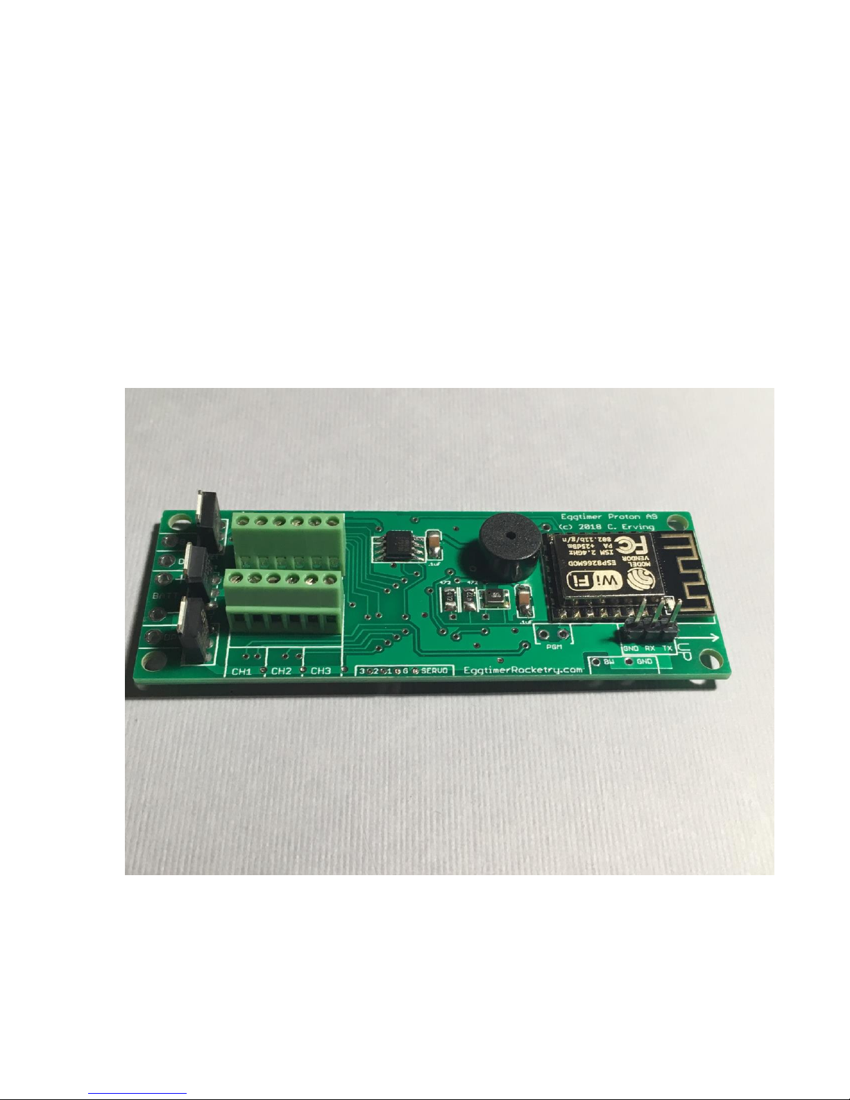
Meet the Eggtimer Proton
The Eggtimer Proton is an advanced hobby rocketry flight computer with a barometric pressure
sensor, 120G accelerometer, and six high-current output channels. Its job is to properly deploy
your parachutes and bring your high-powered rocket safely to the ground, and to record flight
information for later analysis. In addition, it can handle other events such as airstarting motors
or just about any other event that you can come up with. Each channel can be programmed
independently for whatever function you need. In addition, channels can be "clustered" so that a
single event triggers multiple channels, perfect for cluster airstarts. Channels can be triggered by
a number of different events for an almost unlimited combination of scenarios.
It’s nice to get your rocket down in one piece, but it’s also nice to know how the flight went.
The Proton can record your last 14 flights, and you can easily view and/or download both
summary statistical information and detailed time vs. event information. The detail output
format is a standard .csv file, which can be imported into virtually any data analysis program.
What makes the Proton different from most other flight computers is that it has a WiFi interface.
Instead of using switches, jumpers, or a data cable to your laptop to program it, you simply
connect to it with your phone, tablet, or computer using WiFi and a browser like Safari, Firefox,
Internet Explorer, or Chrome. You remotely arm it at the pad using your handheld device too, so
for many applications you do not need a mechanical switch… it won’t turn on until you tell it to.
Flight data is downloaded to your handheld device using WiFi, and with the installation of an
appropriate spreadsheet or other data analysis program you can actually get a flight graph within
seconds of recovering your rocket.
Since one of the tenants of successful electronic deployment is ground testing, the Proton
incorporates a ground-test feature so that you can check YOUR battery with YOUR igniters to
make sure that they are compatible and will work in flight. This is done remotely over WiFi, so
you can even test with “live” pyro charges, standing up to 100’ away from your rocket.
The output channels are capable of triggering just about any load that you’re likely to encounter,
we’ve even fired a medium-current Estes igniter with it using a 2S/7.4V LiPo. You can set the
output on-time from 1-9 seconds, so it’s ideal for use with a hot-wire non-pyro deployment.
There’s a separate battery input for the deployment circuitry, so you can optionally use a second
battery on the deployment outputs that 100% guarantees that a deployment glitch will not cause
your Proton to “brownout” due to low voltage. Each channel is overload protected so they can't
be blown out with an accidental short.
You can also use standard PWM hobby servos with the Proton, for non-pyro deployments. This
makes it ideal for use by TARC teams that want to experiment with electronic deployment but
can’t use pyrotechnics, or for flights over 30,000’ in which pyro charges may not be effective.
In addition to deployment functions, the Proton can also be used to “airstart” additional motors in
flight, either for “strap on” boosters or for starting a second stage motor. It works as a timer that
starts at launch, and is qualified by breakwire support, velocity-at-time, and/or altitude at time.
There is also a Barometric-Altitude-Deviation calculation that won't fire your airstart motor if
the rocket is moving off-axis. This helps ensure that your second stage won’t light unless your
rocket is going “up”.
Page 5

- 5 -
Getting to know your Proton
Although the Proton seems relatively simple, you will want to familiarize yourself with it
BEFORE you install it in a rocket, and certainly before you try flying it.
Battery (BATT) – Two solder pads for connecting the Proton’s battery. It's polarity protected,
so if you hook up the battery backwards it won't damage anything. We recommend a 2S/7.4V
LiPo battery, 300 mAH or higher… more on that later.
Buzzer - “Beeps” out status, warnings, apogee at landing, and other important notifications.
Output Channels (CH1-CH6) - Six sets of deployment output terminals, each with a 10A/40V
capacity.
Battery Output (B+) – Used for the single-battery option when jumpered to the DP+ pad.
Deployment Power (DP+/DP-) – Two solder pads for connecting a separate deployment
battery. If you choose to use the Proton with a single battery for both the computer and the
deployment side, you simply jumper the DP+ pad to the B+ pad, which provides the power for
the deployment channels.
Servo Outputs - Three pads marked "1" through "3", and one labeled "G", for connecting logiclevel servos. These are mirrored to the CH1-CH3 output channels.
Programming Cable Header – 3-pin header that’s used with an Eggtimer USB-Serial cable for
updating the software or for viewing the WiFi passkey (in case you lose it).
Programming Jumper Pads (PGM) – Two pads used to put the Proton into programming
mode at boot-up, for uploading software updates. Normally you won’t do anything with these
pads.
Page 6

- 6 -
Mounting Your Eggtimer Proton
IMPORTANT: Your Proton must be mounted so that the "UP" labels on the board are
pointed towards the nose cone of your rocket!
The Proton is relatively small and light, and can be mounted several ways. The most common
way of mounting it is using four #4 screws, either self-tapping screws for wood sleds (put a drop
of CA glue in the hole first to prevent the screws from loosening in flight) or machine screws
(we recommend using Nylon-insert nuts so they don’t come loose). We recommend that you use
Nylon washers between the board and the screw heads to prevent any possibility of shorts.
You’ll also need to put some kind of spacer between the bottom of the board and the sled, about
3/16” high. There’s a mounting template on the Eggtimer Rocketry web site to help you plan
your installation.
We do NOT recommend using double-sided foam “servo” tape to mount the Proton to your AV
sled. There are parts on both sides of the board, so the bottom isn’t flat. You won’t get 100%
coverage with the servo tape, so there’s a potential for it coming loose in flight, which is bad.
Also, when you pull it off, you might lift a part off the PC board… that would be bad too.
However you mount it, be careful not to overtighten the screws and possibly bend the circuit
board. The parts on the bottom of the board can break if you force them against the bottom of
your sled… don’t ask us how we know. We recommend that you leave a little space between the
board and the sled… about the thickness of a credit card.
The Proton should be mounted so that the "UP" markings near the WiFi module face the nose of
your rocket. You also want to make sure that the holes are drilled properly so that it faces as
vertically as possible. If you get it a tiny bit crooked it's not going to matter much, but the more
care that you put into the mounting the better your results will be.
Since the Proton primarily uses a barometric pressure sensor to determine altitude, you’ll need to
drill a few holes in your AV bay to vent it to the outside air. There’s a lot of debate about what
the right size for the holes is, how many, etc., but the most accepted rule of thumb is: One ¼”
diameter hole for every 100 square inches of AV bay volume. For most average AV bays that's
going to be three 3/32" to 3/16" holes.
Now the tricky part is that you don’t want ONE vent hole… the optimum number is THREE,
equally spaced along the AV bay perimeter. This works out to about three 5/32” holes for every
100 square inches of volume. That’s just about the size of a 4” diameter AV bay that’s 8” long,
so you can work up or down based on that. We also recommend that you don’t mount it so that
the pressure sensor is directly across from the vent holes in your AV bay. You can get funny
currents during flight, which may compromise the accuracy of the altitude readings.
Wiring Your Eggtimer Proton
The Proton is designed to have the power connector wires directly soldered to the board, and
outputs connected using the screw terminal blocks. You can also omit the terminal blocks for
the outputs and solder pigtails to the output pads on the board, so you can use whatever method
Page 7

- 7 -
of terminating the connections you want: barrier strips, solder directly to pigtails, throughbulkhead terminals, etc. Soldering connections to the board prevents the connections from
coming loose in flight due to vibrations and G-forces.
We’ve found that simply wire-wrapping the igniters to a “pigtail” wire soldered to the board
works very well for smaller rockets. By soldering the pigtails to the board rather than having
screw terminal blocks, you eliminate the possibility that the wire may work loose from the
terminal in flight. It saves space too, which is usually at a premium with 38mm and skinnier
rockets. We also like the wiring kits sold by Binder Design Rocketry, the wire they supply is
Teflon-jacketed and lends itself well to solder-type wiring. Their charge wells with integral
through-bulkhead terminals als work great for 39mm-54mm rockets.
We recommend using #22-#26 gauge wire for wiring to the Proton board, we like to use the #24
gauge stranded wire that’s found in Cat-5 network cables. It’s cheap, easy to find, and just the
right size. It’s also twisted together in nice solid-striped pairs, so it’s easy to tell the “+” from
the “-“ wire. If you can, get the “plenum” cable, since it has a Teflon jacket and doesn’t melt as
easily when you solder to it as the standard “riser” cable. You can also use solid wire, but solid
wire is harder to work with and has a tendency to break after being bent a few times. These
breaks can be a pain to find, because they are typically inside the insulator jacket where you
can’t see them.
If you use stranded wire, you MUST TIN THE WIRES BEFORE SOLDERING TO THE
BOARD. This is to prevent stray “whiskers” of wire strands from coming loose and bridging
pads, or breaking off and landing on the board in some random place. We’ve seen the results of
this happening, it’s not pretty, and they can be very hard to find if the lodge underneath the
processor chip or in some other hidden spot on the board.
If you build the board with the terminal block option, be sure to tin whatever wires you are using
for your igniters before you insert them into the terminal block. Loose strands here can prevent
deployments, if a strand comes loose and lodges in the wrong place it could cause an immediate
deployment when you connect the battery. That would be bad…
Last, but not least, we strongly recommend that all wiring on your sled be zip-tied to the sled so
that there’s no chance of any wires coming loose in flight. We’ve seen it happen, and the results
are not pretty.
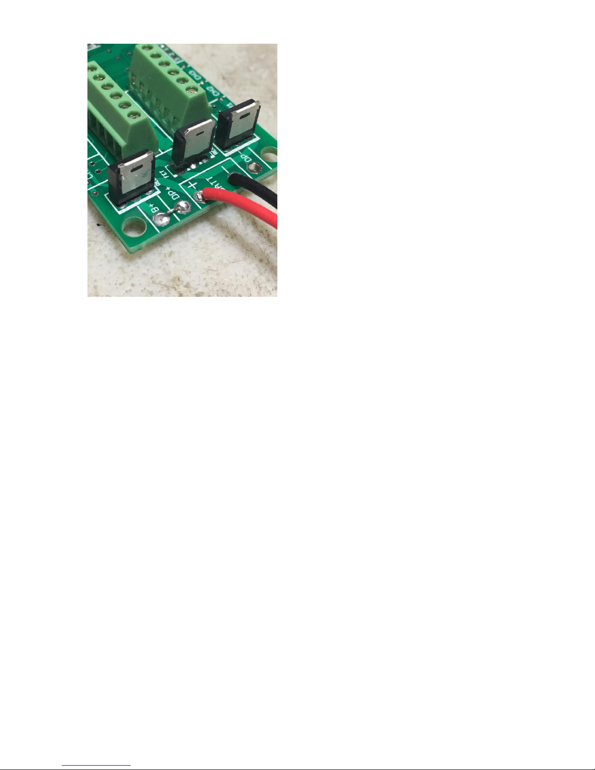
The Single-Battery Option
For a single battery, you only need to solder a jumper (or switch, see below) between the B+ and
DP+ pads that are located next to the two BATT pads. This will provide power to the
deployment circuitry directly from the battery. Nothing else is necessary... see the picture below.
Page 8
- 8 -
The Dual-Battery Option
Using separate batteries for the Proton’s computer and deployment side has some advantages,
and one disadvantage. The disadvantage is that it’s going to take more stuff… one more battery,
one more connector, and possibly, one more switch. The advantages that: 1) You can use a
different voltage battery than the computer side, which you may want to do for servos; and (the
big one) 2) No matter what happens on the deployment side, including a complete loss of battery
power, it’s not going to affect the computer side. This is the same philosophy behind the dualbattery architecture on other Eggtimer Rocketry flight computers such as the Eggtimer Classic
and the Eggtimer TRS.
Some other flight computers use a big capacitor on the power output, with a single battery to
prevent brownouts. This protects against momentary disconnects such as a glitch due to Gforces when your drogue deploys, but it won’t protect against a longer-term brownout such as a
shorted ematch after firing. Once that capacitor drains, your altimeter is done. With the dual-
battery setup, if you have a short on the drogue it’s going to cause a high current drain for a few
seconds until either the processor shuts the output transistor off, or until the transistor blows (not
likely, by the way). Either way, that high current draw is going to stop. Unless your battery gets
totally fried during these few seconds (also not very likely…), when the command is sent to the
main to fire it’s going to work.
To wire up your Proton for dual-batteries, wire the +/positive side of the battery connector to the
DP+ pad (next to the BATT pads), and the -/negative side of the battery to the DP- pad (located
between the deployment output pads). Leave the B+ pad unconnected. If you are going to be
using a separate disconnect switch for the deployment battery you will generally wire it in series
with the +/positive side, so that it goes between the DP+ pad and the +/positive lead of your
battery connector.
Page 9

- 9 -
If you use a separate deployment battery, remember that you will not see continuity on either
channel until you power on the deployment battery. If you use a switch, we recommend that
you turn it on to test igniter continuity at your work table BEFORE you add the pyro powder to
your charge wells, then shut it off until you’re safely on the pad. Turning on the deployment
power does NOT power on the deployment FET; it only allows the trickle current to go through
the circuitry to test continuity.
About Switches…
The Proton is designed so that it will not self-arm itself. If you power it up, it will sit there on
the Status page forever, changing the validation code every 60 seconds… you have to actually
arm it using the validation code in order to start a flight. In addition, the unique dual-ended
deployment output prevents any significant current from getting to the igniter until it’s armed
and actually in-flight.
Because of this, for most flights using electronic deployments up through NAR/TRA Level 2
you do not necessarily need a separate power switch if you’re using the single-battery option.
You can simply connect the battery to a locking connector such as a JST connector and you’re
ready to go until you arm it on the pad. This makes your AV bay build easier and smaller, and of
course it makes your pre-flight procedure a lot simpler.
The Proton is different than most other altimeters because it has dual-ended switching on the
deployment outputs: BOTH the “+” and the “-“ side are switched off, leaving the igniter
essentially dead until it's actually in flight (except for a tiny trickle current that’s used to test
continuity). For the igniter to fire, both sides have to be activated independently, and this can’t
happen until you’re in the air and the deployment enabling logic has been triggered.
This meets the NFPA and Tripoli/NAR requirement that pyrotechnics be de-energized until
ready for flight. However, FOR LEVEL 3 CERTIFICATION FLIGHTS ONLY you may need
to add a switch to the pyro outputs. As of the date of publication (Sept. 2018) Tripoli allows
electronic switches for L3 certification projects, subject to the approval of the TAP's. NAR
requires a mechanical disconnect for L3 certification flights.
In the event that you do decide to add a switch, you have a few options, since the Proton can use
a separate power supply for the deployment devices.
If you are using a single battery for both the computer and the deployment side and you need to
use a deployment disconnect switch, you can simply put a switch between the B+ and DP+ pads
instead of a jumper. Turn on the switch when you’re on the pad to power up the igniters,
confirm that everything is OK, then arm your Proton and go.
If you are using a separate battery for the deployment side, you can put the switch in series with
the deployment power that goes on the DP+ pad. This is our recommended configuration for
Level 3 rockets because having the separate deployment battery 100% prevents any kind of
deployment glitch from affecting the flight computer side. Doing it this way allows you to
make whatever changes you may need to make (for example, lowering the Main deployment
altitude if the wind picks up a bit) while leaving the deployment side powered off.
Whatever switch you use, make sure that it can handle the expected G forces that you expect the
rocket to experience during flight. In general, we recommend that if you use a slide switch that it
Page 10

- 10 -
is mounted so that it slides sideways, not up and down. This will prevent G forces from possibly
causing the switch to “bounce”, interrupting the power to the Proton, which is not a good thing.
Any slide switch that you use must be rated to at least twice the G forces that you are likely to
see… a $1 Radio Shack special isn’t going to cut it, spend a few bucks and get a high-quality
switch.
You can also use a “push-on, push-off” type switch. Many users have had good success with
them, also mounted laterally. You can put the switch just behind one of the air ports, and actuate
it by pushing a small pin/wire through the hole. Just like with slide switches, spend the money to
get a good quality switch.
A better option would be a more positive switch, such as a rotary switch or a screw-type switch
that locks down positively. Since the major forces on rockets are almost entirely along the
longitudinal axis of the rocket, the contacts on a rotary switch are unlikely to be interrupted by G
forces. A popular choice is the Schurter 033.4501 rotary switch, they cost about $5. This is a
special-purpose rotary switch originally designed to be a 120v/220v power supply selector
switch, but it works very well for our purposes. You can get them from a number of online
rocketry suppliers, or you can order one directly from Allied Electronics, a direct distributor for
Schurter products. They’re actually about a buck cheaper from Allied, but you’ll have to pay
shipping, so chances are pretty good that you’re gonna come out ahead if you buy it from one of
the rocketry suppliers because you’re probably buying a bunch of stuff from them anyway.
Featherweight Rocketry and Missile Works also make good small screw-type switches, they use
a screw to positively lock down the contacts and completely eliminate any possibility of the
switch being jarred open. You can also make your own screw switch, Google around and you
can probably find some good examples.
Finally, if you want to avoid moving contacts altogether, check out our Eggtimer WiFi Switch
(www.EggtimerRocketry.com). You can turn it on or off using your mobile device too,
independently of your Proton. It may be a bit larger than other switch options but the
convenience of not having to fumble around looking for the switch inside the AV bay more than
makes up for the minor weight and size penalty, and you can safely arm your deployment
electronics from up to 200’ away from your rocket. And yes, the WiFi Switch will not interfere
with the WiFi signal from your Proton.
Proton Battery Options
For most installations, we recommend using a 2S 7.4V LiPo battery. You’ll need one that’s at
least 300 mAH, since the Proton draws 85 mA (it’s WiFi… that’s the nature of the beast). You
CAN get away with smaller batteries, IF (and ONLY IF) you connect the fully-charged battery
up right before flying. We’ve used batteries as small as 180 mAH in testing, but we have several
fully-charged batteries on-hand and we change them with a fresh one after each flight. With a
larger battery, you can take your time… a 500 mAH 2S LiPo is about the same size and weight
as a 9V alkaline battery, and will last all day. That’s what we use for all but the skinniest of
rockets. For 3" or larger diameter rockets, we like the skinny packs used for Airsoft guns…
Page 11

- 11 -
they’re about 100mm x 18mm x 12mm, so it’s easy to fit them on the back of the sled, and they
have a lot of capacity… about 1200 mAH. You can run all weekend on one charge.
While we’re on the subject of 9V alkaline batteries, DO NOT, repeat, DO NOT use a 9V battery
to power the Proton. At all. They don’t source much current, especially compared to a 2S LiPo.
While it will appear to work fine once it’s new, it will quickly drain, and you will find that the
range starts to rapidly decrease, and the Proton will appear to become unresponsive. If you’re
using the single-battery option, the chance of a low-voltage “brownout” is much higher than it
would be with a 2S LiPo. WiFi takes a lot of power, so make sure you feed it well.
In addition, if you are using a single battery we recommend that the current-sourcing capacity of
the battery should be at least 5x the all-fire current of the igniter (or the sum of the igniters, if
you're firing a cluster), to prevent any chance of the voltage dipping. To get that number,
multiply the capacity in mAH by the “C” number of the battery. For example, a 300 mAH
battery rated at 20C will easily put out 6,000 mA, or 6A. If you igniter is rated for 750 mA allfire, 5 x 750 = 3750 mA, so that 300 mAH/20C battery would be just fine.
If you’re using a separate battery for the deployment side, whatever battery will fire your igniter
or operate your other deployment device (hot wire, servo, etc.) is fine. Little 1S 3.7V 150 mAH
LiPo batteries work great with most ematches, and are so small that you can easily mount them
with a little servo tape just about anywhere you want in your AV bay. The output drivers will
each handle up to 10A and 40V, so if you have something really power-hungry (like a solenoid,
for example), you can simply use a bigger battery. You don't have to worry about "burning out"
the drivers, because they're internally current-limited and thermally-protected; if you try to push
too much current through them, they'll simply shut off until they cool off (kind of like a thermal
circtuit breaker).
You can use a 9V alkaline battery too for the deployment side only with a dual-battery setup
if that’s what you like, just be aware that they’re pretty big and heavy by contemporary
standards. If you do use a 9V battery, one more thing you need to be careful about is that some
brands of 9V batteries simply have cells pressed together in a metal case, so high G forces can
cause the battery to fail. If you absolutely HAVE to use a 9V battery, we recommend Duracell
9V batteries, because they use welded cells internally and are less likely to come apart than some
other brands. If you do decide to use an alkaline 9V battery, we recommend that you replace it
after EVERY flight. Yes, that can get expensive. And yes, you don’t have to worry about your
battery having been drained too much by a previous flight… enough said.
Regardless of what kind of batteries you choose, charge or swap out your batteries before
every session, and check the voltage with a digital voltmeter before every flight. The
voltage check on the Proton is only on the processor battery, it does not test the deployment
battery (assuming it’s separate). You don’t want to spend all the time to find the “perfect”
battery combination for your 54mm minimum-diameter mach-buster only to realize after you dig
it out of the ground after lawn-staking it that you forgot to charge the deployment battery.
Although you probably won't hurt the Proton itself by dead-shorting the outputs, the voltage drop
due to the short may cause the battery voltage to drop low enough to cause the processor to reset,
although the drivers have a low-voltage cutoff at about 4V that's designed to prevent this from
happening. This is why we recommend having a battery current capacity of at least 5x the allfire current of your igniter; if you get a short, chances are that the battery is going to simply
generate a little heat in the drivers and wires for the few seconds that it’s on, then it will be
Page 12

- 12 -
turned off and everything will be OK. If you battery only has a marginal current capability, the
same short may cause the Proton to reset if the voltage drops below the processor threshold
(about 2.8V). The deployment drivers are designed to shut down if the source voltage drops
below 4V, so that theoretically shouldn't happen, but it's better not to chance it. Depending on
when this happens, the effect could range from not getting your peak altitude reading (annoying),
to deploying only the drogue chute (if this happens when you fire the drogue), to a lawn stake if
you’re only using the drogue function and it fails to fire. Ouch. So, choose your battery wisely
if you're using a single battery.
If you’re using an ematch, you only need to set the deployment on-time to one second… if they
don’t fire in a few dozen milliseconds they probably won’t fire at all. If you’re using a hot-wire
(for example, to cut a cable tie or nylon fishing line) you’ll need to experiment with the on-time.
You’re going to want to do this on the ground, of course… flight-time is NOT for experimenting
with your deployment parameters!
Page 13

- 13 -
Using your Proton
What sets the Proton apart from other hobby rocketry flight computers is that it doesn’t use any
switches, jumpers, or cables to configure or download flight data. It’s all done over a WiFi
connection to your handheld device, using a common Internet browser. The pages have been
written very simply so that they do not require Java, Javascript, .NET, or any other scripting
language to operate… they’re all just simple HTML 1.1. The pages are simple text with minimal
formatting, and while they may not be particularly pretty they are very easy to read, and they
render virtually the same on every browser and platform we’ve tested.
About Browsers and OS’s…
All of the Proton’s functions will work almost identically with just about any browser that you
use. Because of the differences in the way that browsers display things and handle downloaded
files, however, you may find that one browser works better than another with your particular
platform. Interestingly enough, some browsers are much faster than others… generally the ones
that are provided by the vendor. Go figure…
In general, our recommendations are as follows, in order of preference:
Apple iOS: Safari, Firefox
Android: Firefox, Safari (yes, it’s an old version…), Chrome
Windows: Internet Explorer, Edge, Firefox, Safari, Chrome
Note that Chrome comes out last on all of these lists. The reason is that Chrome does not handle
the flight detail download function very well. In particular on an Android it can’t tell what to do
with the .CSV file that’s generated from the flight detail download, so it either hangs for awhile
or comes right back and does nothing. It’s a shame, because we really like Chrome, but for this
application it doesn’t work very well. If you have an Android, use Firefox instead, it will display
the .CSV file and launch your viewer if you have one installed.
Individual notes regarding browser compatibility and issues are in Appendix D.
Connecting to Your Proton
Each Proton has its own WiFi SSID network name, which is going to looks something like
Proton_2abcd
The last 5 or 6 characters are derived from the unique MAC address of the Proton’s WiFi
module, so they’re pretty much unique. The Proton uses the WPA2-PSK WiFi connection
protocol, so you need to enter an 8-digit passkey to connect. The passkey for your Proton is on a
label on the WiFi module that you got when you built it. It’s also on a label on the package. If
you accidentally lose it, you can also get it by connecting an Eggtimer USB-TTL data cable to
the programming header. See the Appendix for instructions on how to do this. We recommend
that you put a label on top of the WiFi module with the passkey… you’ll be glad you did at some
point.
Page 14

- 14 -
To connect to your Proton, hook up the battery and wait about 10 seconds for it to initialize.
You’ll hear some beeping as it goes through its self-test, and at the end of the long 3-second beep
it should be discoverable over WiFi. Go to the WiFi Settings on your handheld device, and
browse the wireless networks. You should see your Proton listed as something like
“Proton_1a2b3c”. Choose that network, and enter the passkey when prompted. Hint: When
asked, be sure to check “save the password” and/or “connect automatically when in range”. This
will keep you from having to do this every time. Note that if you have multiple Proton’s you
might NOT want to save the passkey… keep it handy by using a memo pad app on your device.
Open up your browser. If your home page is something on the Internet, you’re gonna get a
“Page can not be displayed” message because you’re connected to your Proton, not the Internet.
That’s OK and normal. Set your browser to the Proton’s home page:
192.168.4.1
and you should see the Status Page. At this point, you should Bookmark this page so you don’t
have to re-enter the address every time… you’re going to be going here a lot.
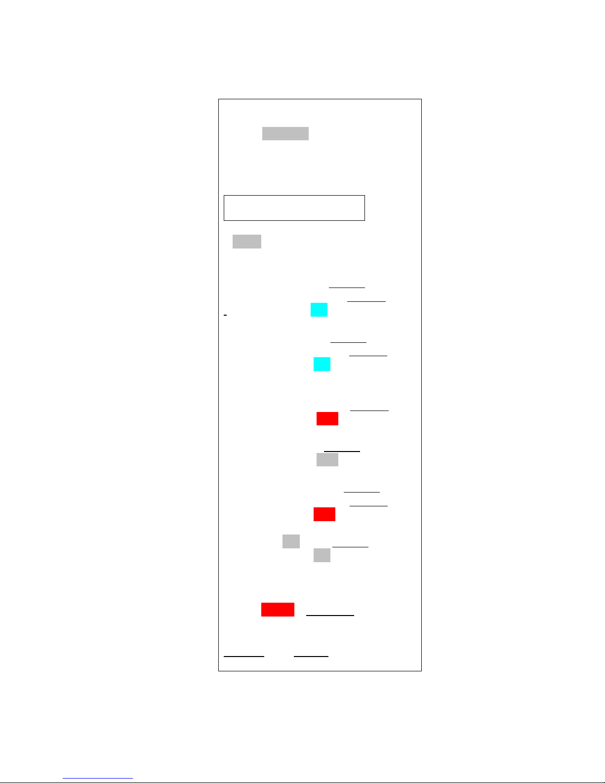
The Status Page
The first thing you will see is the Status Page. It tells you what your Proton is doing, and gives
you some other important information:
◦ Device Name (important if you have more than one of them in your rocket!)
◦ Flight Status: Armed or Disarmed
◦ Deployment channel status, settings, and link to change the settings (see below)
◦ Computer-side battery voltage
◦ Above-Sea-Level (ASL) altitude
◦ G's from the accelerometer (should be about 1.0 for vertical and 0.0 for horizontal)
◦ Temperature (it may read low for awhile… it takes 10-15 minutes to stabilize)
For arming:
◦ The current validation code (it changes every 60 seconds that you’re idle)
◦ A text box to enter the validation code into for arming
◦ An “ARM” button for arming (once you type in the validation code)
Links:
◦ Deployment channel “Change” links – for changing deployment channel in-flight settings
◦ Settings – takes you to the Global Settings page
◦ Flights – takes you to the Flight Select page, for displaying saved flight info
Page 15
- 15 -
Proton_2abcd 1.01a
Status: Disarmed
Validation Code:
4567
…………………………
ARM
Channel 1: Drogue Change
Delay: 0.0 Settings
Channel Status: ON
Channel 2: Main Change
Altitude: 500 Settings
Channel Status: ON
Channel 3: Airstart
Delay: 2.2 Settings
Channel Status: OFF
Channel 4: OFF Change
Channel Status: OFF
Channel 5: Clustered Change
Channel: 3 Settings
Channel Status: OFF
Channel 6: Off Change
Channel Status: ON
Battery: 8.0v
ASL Alt: 1050 ft
Accel: 0.03 G Calibrate
Temp: 74.2
Settings Flights
Page 16

- 16 -
Depending on what you have hooked up to the deployment channels and how it’s powered, you
may see the deployment channel status displayed in different colors. The colors are:
◦ Silver – Status does not affect arming (channel turned off, for example)
◦ Aqua - Good deployment status, i.e. channel is enabled and you have continuity
◦ Red – No continuity on enabled channel, arming not possible
The Proton updates the deployment status every time that the page refreshes. If you leave the
page alone, it will refresh every 60 seconds. When it refreshes, you’ll hear a little beep from the
speaker... this also lets you know that you’ve got power and are connected to your Proton. In
addition, every time the page refreshes a new validation code is created. You can force a page
refresh by hitting the refresh icon on your browser, or by clicking on the ARM button without
entering a validation code or entering an invalid validation code.
Calibrating the Accelerometer
You will notice that no matter which position you hold the Proton at after power-on, the Accel
number will be in RED. This is because the accelerometer has to "warm up" after power is
applied before the readings become stable; up until that point, the readings may drift from the
"actual" value. Once the accelerometer stabilizes, it can be used for flight, but first it needs to
be calibrated to compensate for whatever drift may have accumulated during the five minute
warm-up period. You CAN NOT arm the Proton for flight until the accelerometer has been
calibrated...
YOU NEED TO CALIBRATE THE ACCELEROMETER BEFORE EVERY FLIGHT
To calibrate the accelerometer, set the Proton horizontally; assuming that it's mounted in your
AV bay, just lay your AV bay on the table. Click on the "Calibrate" link next to the Accel
reading on the Status Page. If you do not see a "Calibrate" link, that means that the warm-up
period hasn't been reached yet... just be a little more patient. The warm-up period is five
minutes, so it shouldn't be long. Once you click on the Calibrate link, you'll see this screen:
Page 17

- 17 -
Proton_2abcd 1.01a
Accel Calibration
Lay your Proton
HORIZONTALLY
then click on the button below
Current Accel: 0.03 G
Auto-Adjust v
Calibrate
The default Option is to auto-adjust the calibration, which will take a reading and subtract it from
zero (since you're horizontal...). This is what you should choose if you are going to fly. When
you click on "Calibrate", the accelerometer offset will be calculated and it will be used from that
point on until you reset the power; you will be then be returned to the Status Page.
You can also click the down tick next to Option and select "Zero Offset"; that will zero the
offset, allowing you to see what the uncorrected Accel value will be on the Status Page. If you
do that, you will need to go back to the Calibrate link and select Auto-Adjust; the Proton WILL
NOT ALLOW YOU TO ARM if you select Zero Offset. It's strictly for your edification...
sometimes it's interesting to see how far the accelerometer has drifted.
Arming Your Proton
In order to start a flight, you need to arm the Proton. For safety reasons, the Proton will not selfarm; that is, you must go to the Status page and arm it by entering the current Validation Code in
the text box and clicking on the Arm button for the flight sequence to begin. This is different
than most other flight computers, which will automatically go into an arming sequence a short
time after powering up, assuming that the continuity is OK. The Proton is a little bit different
because it’s assumed that you’re not using a power switch so you are basically using the arming
sequence as a remote switch. This is the reason why we have the dual-ended switching
architecture; it ensures that your ematch/igniter is essentially “dead” until the Proton has been
armed AND you have a flight in progress. This virtually guarantees that you cannot fire a
deployment charge (or an airstarted motor...) on the ground.
Before you can arm the Proton, any enabled deployment channels must be in a flyable status.
This means that if a channel is enabled there must be continuity; if a channel fails the continuity
test then you will not be able to arm your Proton. You can tell very easily from the Status page if
it’s ready to fly, because any failed channels with have the continuity status highlighted in RED.
Note that if you've selected a servo deployment option the status will always be in GREY; there's
really no way to tell if a servo is connected or not, because they're an output-only connection.
It's assumed that they are always in a flyable state.
Page 18
- 18 -
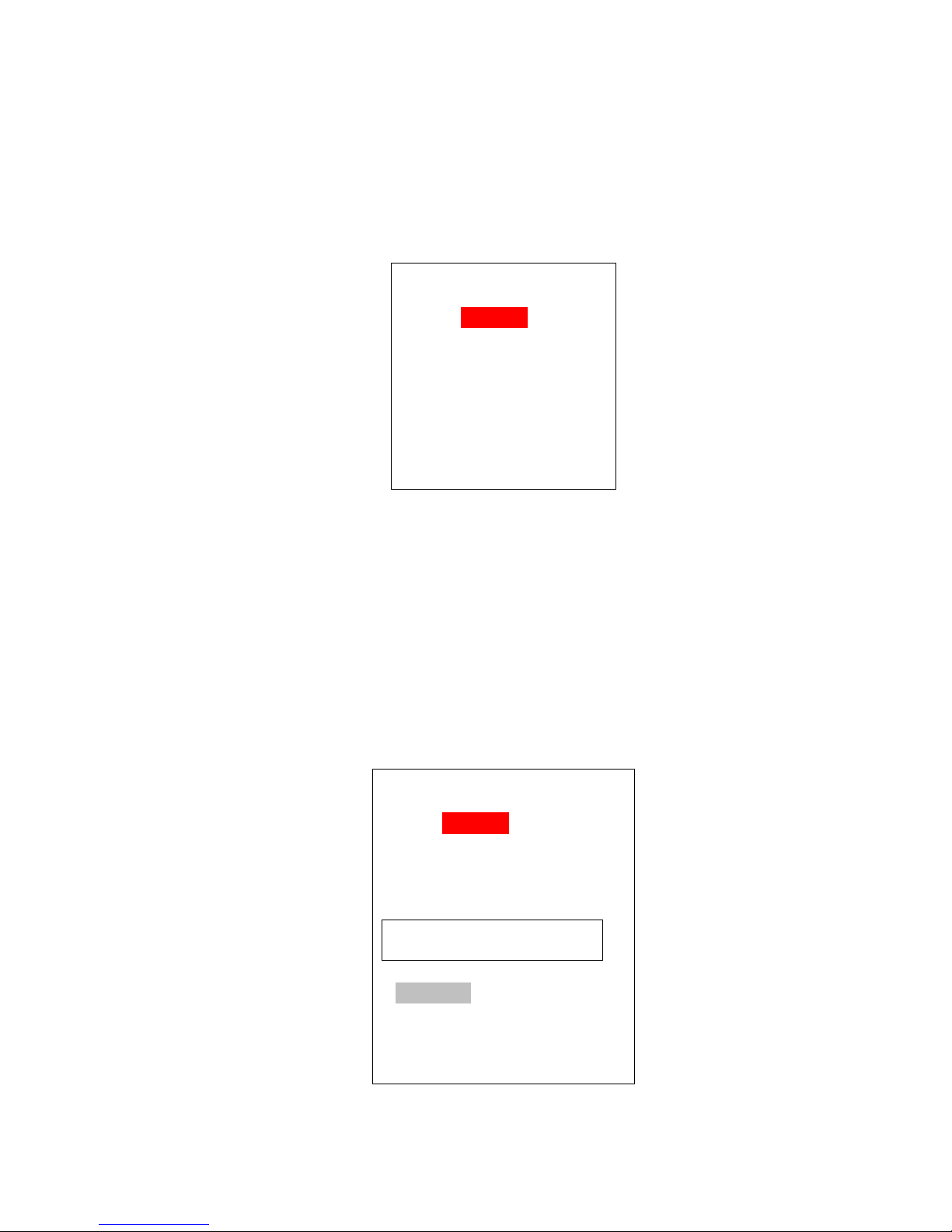
In addition, your rocket must be in a vertical state, i.e. it must be pointing "UP" to arm it. If the
Proton_2abcd 1.01a
Status: ARMED
Please CLOSE
this Page!
Battery: 8.0v
Proton_2abcd 1.01a
Status: ARMED
Validation Code: 8509
…………………………
DISARM
Battery: 8.0v
Proton sees that the G's are under 0.80G or over 1.20G it will not arm. Note that the
accelerometer will drift over time, so you need to perform a calibration before you fly it in order
to compensate for this. See the previous section regarding accelerometer calibration.
To arm the Proton, enter the 4-digit validation code into the text box then click on the ARM
button. After about 5-10 seconds you should see an arming confirmation page:
This page looks a lot like the status page, but the status is changed to “ARMED”, it doesn’t
initially have the validation code/box, and only the battery voltage is displayed. A few seconds
later you should start hearing the buzzer beep about once per second. This is an audible
confirmation that the Proton is now in flight sequence mode, and you’re ready for launch. At
this point you should CLOSE the browser window on your handheld.
Until the flight actually starts, the Proton will be listening for activity from your handheld. If
you refresh this page or re-connect you will see the same page, but with a validation code, text
box, and “DISARM” button, as shown below:
Page 19

- 19 -
This allows you to end the flight sequence in case you have an issue, i.e. you burn an igniter and
the rocket doesn’t launch. In that case, you’d perform a disarm prior to approaching the rocket
to insert a new igniter, then re-arm it afterwards. Note that refreshing this page will halt the
flight sequence for about 5 seconds while it performs processing and updates the statuses, which
is why you should close the browser on your handheld after arming. Closing the browser
window after arming helps to prevent potential interruptions to the flight sequence. Note that if
you refresh the Disarm page without entering a validation code it will force a deployment status
and battery check; this is OK if you intentionally want to do this, but remember that it also halts
the flight sequence for about 5 seconds, so don’t do it right before launching, and remember to
close the browser when you’re done.
See the section titled “Flying With Your Proton” for a further discussion of flight events.
Page 20

- 20 -
The Deployment Flight Settings Pages
Each of the six channels can be programmed to perform in any of several different modes. Some
of them are "traditional" in the sense that if you've flown with other flight computers
(particularly an Eggtimer Quantum) you'll be familiar with their function. The modes are:
OFF - Just what it says… turns the channel off because you're not using it.
Drogue - Emulates a traditional drogue chute, firing the channel at some time past apogee. Also
supports servo deployments on CH1-CH3.
Main - Emulates a traditional main chute, firing the channel at some pre-programmed altitude
during descent. Also supports servo deployments on CH1-CH3.
Airstart - Fires the channel at some pre-programmed time after launch detect has been reached
on the way up. Designed for airstarting motors, you can qualify the channel with altitude,
velocity, and Barometic-Accelerometer-Deviation, as well as breakwire support.
Clustered - The channel is "clustered" with another channel, so when the other channel fires this
channel fires too. Designed for airstarting multiple motors, it adds some additional safety
options that you would not get by simply hooking up the igniters together. It also allows you to
devote a full 10A of current to each igniter, instead of divying it up among them. (Obviously,
your deployment battery has to be able to support the extra current!)
When you change a channel from one mode to another, it automatically clears the settings for
that channel and sets up some commonly-used defaults. For example, if you change a channel
from OFF to MAIN, it will set the channel to fire at 500' AGL, using igniter mode with a 1
second pulse width.
Changing a Channel's Mode
To change the mode, you click the Mode description link for that channel from the Status page.
You'll get a Mode Change screen for that channel:
Page 21

- 21 -
Proton_2abcd 1.01a
Mode Setting
Channel 1:
Mode: Main v
Off
Drogue
Main
Airstart
Clustered
Submit
Proton_2abcd 1.01a
Drogue Settings
Channel 1:
Delay: 0 secs v
Deploy Mode: Igniter v
Pulse Width: 2 secs v
Submit
Select the mode that you want to assign to that channel (you may have to click on "Done" or
"OK" depending on your browser), and click the Submit button. After you do that, you will get
the setting screen appropriate for the mode that you selected. Also, when you change modes
that channel's settings will reset to the default values for that mode.
Drogue Settings
The Drogue Settings page is accessed by clicking on the “Change” link next to the Drogue status
on the Status page. When you click on the link, you’ll see this page:
The purpose of this page is to set the delay from nose-over for firing the drogue, and other
related settings. For most dual-deployment flights, you’ll probably want the drogue to fire as
close to apogee as possible, in the Proton this would be approximately one second after apogee.
Page 22

- 22 -
That’s what we call “nose-over”, since it’s pretty much guaranteed that your rocket is pointing
downward. There’s also a low-velocity check, your rocket has to be going relatively slowly
before the deployment channels are enabled. For most flights that will be a second or two
before apogee.
In general, if you’re using dual-deployment then you should set this to ZERO. The other settings
are designed for delaying the drogue using the Proton as a backup deployment controller in a
dual-controller redundant setup, or for special-purpose uses (i.e. the 5-second setting is designed
for ejecting ARLISS CanSats... if you're not familiar with them, check out www.arliss.org, it's
very cool). Typically, the backup controller will have the drogue setting delayed slightly from
the primary controller, so that if the primary controller fails the backup will fire and deploy the
drogue. You should model your flight with a program such as OpenRocket or Rocsim in order to
determine the best delay setting, you want to make sure that the rocket won’t be going too fast
before the backup controller deploys the drogue. Typically, 1.0 to 3.0 seconds is adequate.
The fields are:
Delay (0-9 secs, default is 0):
Set the time delay from nose-over to deployment.
Deploy Mode (Igniter/Servo, default is Igniter):
Selects Igniter mode (on-off) or servo mode (CH1-3 only).
Pulse Width (Igniter mode only): (1-9 secs, default is 1):
Controls how long the output will fire in Igniter mode.
Servo Skew (Servo mode only): (CCW 100%-CW100%, CH1-3 only, def. is 100% CCW):
Controls how far the servo will move when triggered. When the servo is Reset, it will go in the
opposite direction the same amount, i.e. if you have it set to CCW 75% it will go to CW 75%
when reset.
About Servo Mode…
Servo mode assumes that the servo is going rotate to the selected position relative to the zero-
degree center position when actuated, and it’s going to rotate in the opposite position by the
same amount when reset. Typically, you’re going to use some kind of trap-door or pull-pin
mechanism, and there needs to be some way to close the door or reset the pin before you fly.
That’s done with the Test Menu… more on that in the Appendixes.
The servo pulses are sent for 2 seconds, which is plenty long enough for any servo. Once the
two seconds are up, no more servo pulses are sent, so the servo basically stays where it is, at the
end of its selected travel.
Direction/Skews are in relation to the center point of the servo’s travel. Ideally, a servo would
have 180 degrees of travel, so full counter-clockwise (CCW) would go 90 degrees to the left of
center, and full clockwise (CW) would go 90 degrees to the right of center. The reality is that
many servos do not have 180 degrees of travel, so we label them by percent of travel which is
ALWAYS related directly to the standard pulse-width of the servos (1.0 to 2.0 ms in a 20 ms
window).
Page 23

- 23 -
This label is the “Set” direction of the servo, i.e. the direction/skew that it will rotate when
triggered during deployment. The opposite direction/skew is the “Reset” direction, that’s what
you will normally use in the Test Menu.
Values are:
100% counter clockwise (CCW)
75% CCW
50% CCW
25% CCW
0% - Center (you can't select this, we just show it for reference here)
25% clockwise (CW)
50% CW
75% CW
100% CW
Important Note: If you change a channel from Igniter to Servo deploy mode (or back), the
servo direction/skew or igniter on-time settings will NOT be changed. These settings are
dependent on the mode that you choose. You MUST click on the Submit button to change the
mode, THEN you need to go back into the channel's settings menu and select the proper on-time
or direction/skew. This is because web pages are written when the page is first loaded, so any
change you make to that page that’s dependent on another setting requires the page to be
reloaded.
Main Settings
This page allows you to set the descent altitude at which the Main chute deploys, or to turn it off
if you’re not going to be using it. You can set it from 100’ to 500’ in 50’ increments, and 600’ to
2,000’ in 100’ increments.
The Main altitude that you use depends on a lot of things: the size and layout of your flying
field, how much wind is present, how many trees there are around you, the size of your rocket,
and not the least, how far you’re willing to walk to retrieve your rocket. 500’ is the default
setting when you first power up your Proton, it’s adequate for probably 80% of all flights. If you
field is smaller or if there's a fair amount of wind, you’re going to want to take that down a bit,
so your rocket doesn’t drift as far when the Main is deployed. If you have a big project, you may
want to turn that up a bit, since you may not want a larger rocket deploying that close to the
ground and the larger chute may take more time to open. If you’re not sure what setting to use,
ask your buddies at the field… it’s guaranteed that they will have an opinion on the subject!
To change this setting, click on the drop-down list and scroll to the setting that you wish to set.
Depending on your browser/OS, you will either click on it or click a “Done” button to select it.
Click on the Submit button to save it, and you will be returned to the Status page. An example of
the page is shown below.
Page 24

- 24 -
Proton_2abcd 1.01a
Main Settings
Channel 2:
Altitude: 500 v
Deploy Mode: Igniter v
Pulse Width: 2 secs v
Failsafe: Time 1.0 v
Vel. 100 v
Submit
Altitude (100'-2000', default is 500') :
Deployment altitude for the event. When your rocket descends from nose-over to this altitude or
below, the channel will fire.
Deploy Mode (Igniter/Servo, default is Igniter):
Selects Igniter mode (on-off) or servo mode (CH1-3 only).
Pulse Width (Igniter only, 1-9 secs, default is 1 sec):
Controls how long the output will fire in Igniter mode.
Servo Skew: (Servo Only, CCW 100%-CW100%, CH1-3 only, default is 100% CCW)
Controls how far the servo will move when triggered. When the servo is Reset, it will go in the
opposite direction the same amount, i.e. if you have it set to CCW 75% it will go to CW 75%
when reset.
Failsafe Time (OFF, 0.3-3.0 sec, default is OFF):
Controls the time for the failsafe check (see below).
Failsafe Vel. (50-300 fps, default is 100 fps):
Controls the velocity for the failsafe check (see below).
The Failsafe mechanism is designed to help prevent your rocket from coming in ballistic due to
drogue parachute failure. Your descent velocity is monitored from the time that nose-over
occurs. If the descent velocity exceeds the Failsafe Velocity parameter for the Failsafe Time
period, the channel will fire as programmed. The idea is that if your drogue chute doesn't
deploy, your main will be deployed at a relatively low velocity somewhat near apogee,
preventing your rocket from coming in at very high speed. Yes, it's going to cause your rocket
Page 25

- 25 -
to drift a lot more than a normal drogue-main deployment would, but that's better than having
your rocket impact the ground at high speed, and/or having the main chute shred because the
deployment velocity is several hundred feet per second, and still having a high speed ground hit.
The proper values of the Failsafe parameters will depend on the size of your drogue chute (or
lack thereof if you're going drogueless), the size of your Main chute (if it's large you may want to
deploy it a little slower to avoid damaging it), the size/weight of your rocket (smaller lighter
paper rockets will fall slower), and how your other channels are set. If you are going to use it,
100 fps for 1.0 sec is a good starting point assuming a standard dual-deploy rocket with a drogue
chute with a 50-70 fps descent rate. Note that if you have multiple channels set to Main Mode,
you can enable Failsafe for more than one of them, we recommend that they're separated by at
least 0.5 secs to prevent overpressurizing your main chute payload pay (assuming you're using
multiple charge wells).
Airstart and Clustered Settings
Airstart and Clustered modes are typically used for firing motors or separation charges while the
rocket is moving "up". There's a lot of complexity that goes along with this, so see Appendix B
for a thorough discussion of Airstarts and the Clustered mode.
Page 26

- 26 -
The Global Settings Page
The Global Settings page is used to change settings that are either hardware-specific or are not
generally changed from flight to flight. You get into this page by clicking on the “Settings”
link on the Status Page:
Launch Detect Altitude (LDA) (100’-500’ by 50’, default 200’)
This setting allows you to select at what altitude the Proton decides that a valid flight has started.
The 200’ default is good for most flights. However, there may be some cases in which you may
want to turn it up, and some very special cases in which you may want to turn it down.
If your flying site is subject to wind gusts, you may want to turn it up a bit so that when the wind
gust subsides the decrease in pressure isn’t viewed as the rocket ascending. That’s not likely to
happen, however, because we filter the readings to prevent this (and other similar occurrances).
You may also want to turn it up if you increase the Launch Samples per Second.
If you have a very low flight you may want to turn it down, although generally we don’t
recommend it.
Ascent Samples per Second (10,15, 20, 25, 30, 33 samples/sec. , default 20 samples/sec.)
This setting allows you to select the number of samples per second that are taken from the time
that you arm the Proton until it detects nose-over. The default setting (20 samples per second) is
adequate for most flights. However, there may be reasons why you want to turn it up or down.
For example, if you have a very short-burn motor (like a CTI V-Max) you may want to turn it up
to 33 samples per second to make the velocity and acceleration figures more accurate. If you
have a very long-burn motor you may want to turn it down to 15 samples per second, although
20 should be fine. Note that increasing the sample rate decreases the amount of memory at the
expense of flight data accuracy... more on that later.
Descent Samples per Second (1, 2, 4, 5, 8, 10 samples/sec, default 2 samples/sec.)
The setting allows you to select the number of samples per second that are taken after nose-over
is detected. When you’re coming down, you’re generally not going to be going very fast relative
to your velocity going up, even if you freefall for a few seconds and the FailSafe kicks in.
Consequently, there’s really no reason to have the same high rate of sampling that you use for
the ascent part of the flight. Reducing the sampling rate after nose-over saves a lot of memory,
and allows you to record longer flights. For most flights, the default 2 samples/sec. rate is fine.
If you are going over 20,000' you may want to take this down to 1 sample/sec... the reduction in
data accuracy by reducing the sampling rate is minimal.
Page 27

- 27 -
Accelerometer Launch Detect (ALD)
Accel G's: (OFF, 3-20, default 3G)
Accel Time: (0.2 - 2.0 sec, default 0.5 sec)
These settings control the accelerometer launch detect. When the G threshold has been
reached/exceeded for at least the programmed time, a launch detect is triggered and the launch
mechanisms begin. Note that launch detect occurs when EITHER the barometric LDA altitude
OR the ALD is triggered; the first one to trigger a launch detect starts the flight process. If
you're at 50' AGL and you hit the 3G/0.5s threshold, your launch detect altitude will be 50'.
For most flights, the default of 3G for 0.5 sec will be fine. This is high enough that it's unlikely
to be accidentally triggered, and low enough that almost any motor is going to trigger it. There
are a few exceptions of note, however. First are motors like the CTI VMax motors, which
produce a very high amount of thrust for a very short period of time. For those motors, we
recommend setting the time to the minimum (0.2 sec) and setting the G's to a higher than normal
value… 10 G's should work in most cases. For relatively low thrust motors, we recommend that
you turn it OFF, and let the barometric launch detect trigger the launch. We've seen some very
underpowered rockets that never made it to the 3G threshold.
Note that events triggered from the Start of Flight are NOT triggered directly from these points.
Rather, they're back-dated to either the last sample under 10' AGL, or the last sample under 1G
acceleration. It is assumed that whichever one of these came later is an accurate start of flight.
About Sampling Rates and Memory Usage
At this point you may be wondering about how long a flight the Proton can record before
running out of memory, and what happens if that occurs. The Proton saves about 2,000 samples
for each flight. When you’re sitting on the pad or launched and have not yet reached LDA, the
sampling rotates through those memory locations, saving the last altitude reading < 10’ AGL as
the barometric “start of flight”, and the last accelerometer reading under 1G as the accelerometer
start of flight. Once you get a launch detect, the recording continues until either 1) the End of
Flight benchmark (< 30’ AGL for at least 5 seconds) is reached, or 2) the memory wraps around
to the start of flight location. In either case, recording stops there (it won’t overwrite valid ascent
data), but this does NOT affect any pending deployment events… if you run out of memory
before the main chute is deployed, it will still be deployed, but you won’t see it in the data
downloads because it can’t be recorded.
Now, you may be wondering how long a flight you can have with “only” 2,000 memory
locations. Quite a long one, actually. Let’s say that you want to fly to 30,000’ and your motor
will get you there in 30 seconds. At 20 samples per second, that’s 600 samples. That leaves
about 1,400 samples left for the “down” part of the flight. At 2 samples per second, that’s 700
seconds, or over 11 minutes. You’d have to be coming down at a rate of about 40 ft/sec under
drogue to exhaust the memory, there’s no way you’re gonna be coming down that slow from
30,000’ (unless you really like walking a lot). More likely, it’s going to be 50-70 feet/sec. Let’s
say that we come down at 60 ft/sec from 30,000’, that’s about 500 seconds, or 1,000 memory
locations at 2 samples/sec. You’d still have over 400 samples left when you land, nearly 20% of
your memory.
Page 28

- 28 -
If you have an extreme flight, say 50,000’, it may take a bit longer to get up there, let’s say 45
seconds. That’s 900 samples, leaving 1100. If you take the rate down to 1 sample per second
(reasonable since the events are happening relatively slowly and the air is pretty thin at 50K),
you still have 1100 seconds, or over 18 minutes. No way it’s gonna take that long to come
down, unless for some reason the main comes out near apogee. At a conservative 50 ft/sec
average speed under drogue, it’s going to take 1,000 seconds, leaving you with at least 100
samples. Remember that at that altitude the air is very thin, so you’re going to be coming down
faster near apogee than you will be when the air thickens as you descend. It’s very likely that
you’re going to be using a lot less memory than that.
So, as you see, there’s plenty of memory for just about any flight scenario if you manage it
wisely. For just about any flight under 30,000’, just leave it at 20 samples per second for the
Launch rate and 2 samples per second for the Descent rate, and you’ll be fine.
The Flights Page
Clicking on the Flights link takes you to a page that allows you to select a flight for flight
milestone display, and download a detailed .csv file that you can use with Excel or other data
analysis programs to extract graphs and do other fun things. We’ll go into that a bit later…
Page 29

- 29 -
Flying with Your Proton
The Proton is very simple to operate. In general, a dual-deployment flight with the Proton will look
something like this:
At your Work Table
• Charge or swap out your battery/batteries and check it with a DVM to check the voltage
DON’T SKIP THIS STEP!
• Install your igniters with the deployment power switch off (if used), with NO powder.
• Connect your battery to the Proton.
• Turn on your deployment power switch (if used).
• Connect to the Proton and confirm that you have continuity on all selected outputs (unless they're
set for servos). If you don’t, disconnect the batteries and figure out why.
• With your AV bay horizontally on the work table, give it about five minutes to warm up. Check
the Accel reading on the Status Page; if it's near 1.0 then power cycle it (it should be near zero) and
start again. Adjust the Accel Offset from the Settings menu (we recommend using Auto Adjust).
• Check your settings, especially the deployment channel settings
• Close up the AV bay
• Turn OFF the deployment power switch (if used)
• Add powder to the charge wells, and finish prepping your rocket
• CALIBRATE THE ACCELEROMETER
At the RSO Table
• Get your rocket safety-checked, get your pad assignment, and swagger out to the pad. Note that
your Proton will beep shortly once every 60 seconds that it’s powered on, as the web page refreshes.
You may need to show your RSO the Status Page on your phone to show him that it’s disarmed if
he’s not familiar with the Proton, since most Altimeters only beep when they’re armed.
At the Pad
Put the rocket up on the rail/rod, raise it, then go to the Proton’s status page. You should see that the
Accel value is close to 1.00, and it should be AQUA, indicating that it thinks it's pointed "up". If it
is RED, lower the rocket to a horizontal position, go into the Settings menu, select the Calibrate link,
and select Auto Adjust. The Accel value on the Status Page should be near zero, at this point you
can raise the rocket to vertical, if you refresh the Status Page your Accel value should be near 1.00
and the value should be displayed in AQUA.
If you’re using a deployment power switch, turn it on. Make sure that you have continuity on
whatever channels you’re using… if you do not, it’s going to be easy to tell because the status will
be highlighted in RED. If it’s OK, it will be either AQUA or GRAY.
Assuming that all settings are AQUA or GRAY and none of them are RED, enter the validation code
into the box and click on the SUBMIT box, after a second or two you should see the armed page.
Once that happens, CLOSE THE WEB PAGE. Closing the page prevents any data from interfering
with the flight sequence.
Page 30

- 30 -
After a few seconds, you’ll hear a few beeps, then after about 10 seconds of silence (as it takes
baseline measurements) you’ll hear the “I’m ready” beeping, approximately once per second.
Connect your igniter, test the continuity, then go back to the safety zone to await your flight.
If you’re new to dual-deployments, you can see that it’s a lot more involved than just stuffing some
wadding and the parachute into the tube, popping in the motor, and hooking up the igniter. Multiple
deployments require discipline in order to make them work reliably; we’ve seen way more than our
share of failed deployments, on everything from a small mid-power E-size rocket all the way up to
an M-sized 200 pound beast. We’ve seen deployments fail with the top-end flight computers and
with the low-cost units, even with redundancy. The reality is that most deployment failures are not
the fault of the electronics; it’s usually something mechanical like a bad connection, a nose cone
that’s too tight, a chute that gets stuck in the tube, etc. Having your blood, sweat, and tears free-fall
from 10,000’ bury itself in six feet of dirt is going to ruin your whole day.
We STRONGLY recommend that you use a checklist every flight so that you don’t forget anything.
We also recommend that you get a copy of the book Modern High Power Rocketry , it’s full of good
information too, and subscribing to a forum like The Rocket Forum (www.rocketryforum.com) is a
really good idea, too.
In the Air…
Once your rocket is launched, barometric altitude and accelerometer samples are taken at whatever
ascent rate you’ve selected, typically 20 samples per second. These samples are run through a filter
to eliminate “noise” that may be caused by a number of different factors, primarily aerodynamic but
also some external factors such as wind and temperature.
Velocity readings are computed based on the difference between successive accelerometer samples
over time, as well as the difference between successive barometer altitude readings over time. In a
perfect world, this would give you a precise and 100% accurate velocity reading. The reality is
somewhat different, however. There are several things that can introduce errors into the velocity
reading: angle of attack, wind, errors in the pressure readings due to aerodynamic influences, and
time differences. If the pressure ports in your payload bay aren’t sized properly, this can introduce
an error, particularly if they’re too big and you have two of them opposite each other (you’ll get a
crossflow through the payload bay which makes the pressure readings very noisy). Finally,
differences in the processor’s timing may introduce errors, although the readings are taking at
relatively precise intervals so it’s going to be very small.
The good news is that the magnitude of these errors tend to be proportionate to velocity as the rocket
ascends, so they respond well to being filtered with mathematical noise filters. Velocity-related
events are run through a digital filter to smooth out any sharp peaks or valleys that may develop due
to pressure-induced noise.
Mach Transition…
As your motor continues to burn and the velocity increases, if the velocity exceeds 800 ft/sec
aerodynamic shock wave buildup can fool the pressure sensor into thinking that the rocket is
descending when in fact it is actually ascending at a rather rapid speed. If this were not taken into
account, the flight computer might deploy the main parachute at near-mach speed, which would
Page 31

- 31 -
undoubtedly break something and ruin your day, not to mention what an object falling from the sky
at these speeds could do.
To prevent this from happening, the Proton uses a predictive mechanism to hold off deployments
until it’s safely out of the mach “danger zone”. Deployments are initially disabled when the Proton
is armed. When the noise-filtered barometric velocity drops below 100 ft/sec for at least 1 second
after the Launch Detect Altitude has been reached, deployments are enabled. Typically, this will be
a second or two before apogee, although it may be a little later in some cases (i.e. a very draggy
rocket). In any case, it guarantees that your rocket isn’t going very fast when the drogue deployment
occurs, which is the ultimate goal. This is the same logic that we’ve used for several years with all
Eggtimer Rocketry altimeters, and in several thousand flights we’ve never heard of a zipper due to
an early/late deployment that wasn’t due to the rocket going horizontal (or a motor-eject backup
charge firing early).
Apogee and Nose-Over
Assuming that your rocket is moving more or less straight up, it will continue to slow down during
the coast phase until it gets as high as it’s going to go. If the rocket was going absolutely straight up,
the velocity at this point would be zero; it would simply start falling to the ground. In reality, this
almost never happens, because for safety you usually angle the rod/rail at a slight angle so that the
rocket takes off away from the flight line. This results in the velocity disparity that we’ve previously
mentioned. The rocket usually has some forward velocity at apogee; hopefully it’s relatively small
so your parachute deployment happens at a low velocity and won’t cause any mechanical problems
like a broken shock cord or a zippered tube. It also means that you really don’t know that you’ve
reached apogee until after you’ve been there.
Accordingly, the Proton fires the drogue parachute at Nose-Over, which we define as one second
past apogee (highest recorded altitude). If the rocket is still going up, chances are that its altitude is
going to keep increasing before a one second interval elapses, so you’re unlikely to get a false
apogee detection. If the rocket hasn’t gained any more altitude after one second then you must be
starting on your way down, so the Proton fires the drogue at that point, for one second.
When Nose-Over is detected, the Proton begins using the Descent Samples value for altitude
sampling. This setting is very low, typically 2 samples/sec. As the rocket descends, when the
altitude drops below the Main deployment altitude the Main channel is triggered, for one second.
At this point your Main chute should pop out, to thundering applause and a hearty round of highfives all around.
On the Ground
The Proton detects that your rocket is on the ground when the barometrically-detected AGL altitude
varies by less than 30 feet for over 5 seconds. Once on the ground, the Proton will start beeping out
the maximum altitude continuously for anyone within earshot to hear. The beeps work like this:
Page 32

- 32 -
1 Beep = 1
2 Beeps = 2
…..
9 Beeps = 9
10 Beeps = 0
So, if you fly to 12, 360’ you will hear:
Long Pause…
Long Beep… (“I’m going to give you’re the apogee reading…”)
Short Pause…
1 Beep (10,000’)
Short Pause
2 Beeps (2 x 1000’)
Short Pause
3 Beeps (3 x 100’)
Short Pause
6 Beeps (6 x 10’)
Short Pause
10 Beeps (zero 1’ reading)
<sequence repeats>
The beeps continue until you turn off the power, and also act as a verification that you had a
successful flight, but getting your rocket back in one piece pretty much told you that, didn’t it?
In addition, the WiFi interface will start back up again, and will take you directly to the Flight
Summary page for the flight that you just completed. Note that it may take 10-15 seconds to bring
up the Flight Summary page after you connect to the Proton, because it sends out the page after it’s
done beeping out the altitude, so you have to wait until it goes quiet for a few seconds. Once you the
connection, you'll get the Flight Summary page that you see below. Note that this is a "dead end"
page… you cannot go back to the normal Status Page or any other Proton page. This is because
once your flight has ended, it's assumed that you're going to take it back to your work table to open
up the AV bay and recharge the batteries, replace the deployment charges, etc.
Page 33

- 33 -
Proton_2abcd 1.01a
Flight Select
Idx: 01 Flt: 1 No LDA More
Idx: 02 Flt: 2 Apogee: 1827 More
Iex: 03 Flt: 3 Apogee: 3875 More
Idx: 04 Flt: 4 Apogee: 5202 More
Idx: 05 Flt: 5
Idx: 06 Flt: 6
Idx: 07 Flt: 7
Idx: 08 Flt: 8
Idx: 09 Flt: 9
Idx: 10 Flt: 10
Idx: 11 Flt: 11
Idx: 12 Flt: 12
Idx: 13 Flt: 13
Idx: 14 Flt: 14
Exit
Post-Flight Analysis
The Proton saves your last 14 flights: settings, summary data, and detail data. Clicking on the
‘Flights’ link in the Proton’s Status page takes you to an index page that allows you to select the
flight that you want to review. Note that each flight has an index number from 1-14, this is the
memory location that it’s in, and each flight has a Flight number that is sequential from 1 to however
many flights you’ve had with your Proton. If you fly it enough, you’ll probably get to the point at
which flights drop off, and the flight numbers won’t start with 1 anymore, but the indexes will
always be from 1 to 14. Your Proton will roll the flights over to the oldest memory location as
necessary.
Each entry in the Flight Select page shows the Flight Index, the Flight Number, the Apogee, and a
‘More’ link that takes you to the Flight Summary page. Note that after you land and while it’s
beeping out the altitude, it will take you directly to the Flight Summary page for that flight only.
The Flight Select Page
You can view the last 14 flights by selecting them from the Flight Select page, you get there by
clicking on the “Flights” link from the Status Page. It shows you the Flight Index (the location in
memory, 1-14, “Idx”), the Flight Number (which increments every time you start a flight, “Flt”), the
Apogee of the flight (“60335” means that there was no flight), and a link to display the Flight
Summary/Detail for that flight (“More”).
Page 34

- 34 -
Proton_2abcd 1.01a
Flight Summary
Flight No.: 2
Flight Status: Landed
Apogee:.......................1827
Time to Apogee.........2.85
Max Velocity................2060
Time to Max Velocity.......0.25
Max Accel....................10.2
Time to Max Accel........0.25
LD Alt..........................334
Time to LD.................0.05
LowV Alt....................1778
Time to LowV...........4.05
Nose_Over Alt............1778
Time to Nose-Over.... 4.05
CH1: Drogue
Status: Fired OK
Altitude: 1778
Time to Firing: 4.05
CH2: Main
Status: Fired OK
Altitude: 496
Time to Firing: 11.55
Flight Time:...........14.55
ASL Alt................1041
Temp F.................68.1
Exit Detail Settings
The Flight Summary Page
The Flight Summary page gives you a lot of information about what happened during your flight.
You get there by clicking the Flights link from the Status Page. After you land, you can also connect
to it… the Proton will show you only the status for the current flight, plus the detail, until you
power-cycle it. Here, we'll click on Flight #2, the one with 1827 as the apogee...
Page 35

- 35 -
Flight Status – What the last major event was. Typically it will be “Landed”, but it may be
something else if there was an anomaly in your flight.
Apogee – What the apogee of your flight was, and the time-to-apogee from launch detect (LD).
(About the elapsed times: To detect start-of-flight, the Proton uses the first reading above the Accel
Launch Detect G's threshold, before the LDA has been reached. While it’s technically possible that
this figure may be a little off, our experience has shown that it’s only off by one or two samples at
most… typically under 100 ms.)
Max Velocity – The maximum velocity that was reached, and the time from LD. This data comes
from the accelerometer, so it is very accurate, and not affected by the rocket's tilt angle or wind, etc.
Max Acceleration – The maximum acceleration that was reached in flight, in G's. With one motor
it will probably be within a few seconds of the Start of Flight, if you have a multiple stage or
airstarted motor system then it may occur somewhat later.
LD Alt – The actual altitude that exceeded the programmed launch detect settings, and the time from
LD. If the altitude is less than the programmed LDA altitude, you can assume that LD was due to
the accelerometer settings.
Low V Alt – The altitude at which deployments were enabled, i.e. the rocket slowed under 100
ft/sec for at least one second, and the time from LD.
Nose Over Alt – The altitude at which the rocket nosed over, typically one second past apogee, and
the time from LD.
For each enabled channel...
Channel Mode – The selected mode of the channel.
Channel Time – The time from Start of Flight that the channel was fired OR would have fired
if not inhibited
Channel Alt – The altitude at which the channel was fired OR would have fired if not inhibited.
Status Flags – Various flags that show any issues that were encountered that would inhibit the
firing of the channel.
Flight Time – The elapsed time from LD until landing detect, which is when the rocket drops below
30’ AGL for 5 seconds.
ASL Alt – The Above-Sea-Level reading of your launch site.
Temp – The temperature in Farhenheit at the time of launch. This will be very accurate if the Proton
has been powered on for 10-15 minutes, but will tend to be on the low side if you fly shortly after
powering up.
Page 36

- 36 -
Proton_2abcd 1.01a
Flight Settings
Flight No.: 2
LDA Alt......................200 ft
Launch Samp/Sec.........20
Nose-Over Samp/Sec....2
Accel LD Time.............3 sec
Accel LD G's................3 G
CH1: Drogue
Delay.................0.0 sec
On-Time............1 sec
CH2: Main
Alt....................500 ft
Deploy..............Igniter
On-Time...........1 sec
Failsafe:............1000 ms
FS Velocity.......100 fps
CH3: OFF
CH4: OFF
CH5: OFF
CH6: OFF
Exit
As you can see, that’s a lot of stuff to look at. Particularly right after landing, it gives you a pretty
good idea of what happened. For example, we did a test in which we intentionally didn’t install a
drogue charge and left out the motor eject, and turned on FailSafe as a test. (We don’t recommend
that YOU do this, though…) We expected the Main to pop 3-4 seconds after apogee, but that didn’t
happen, instead it came out at about 500’ as if there was a drogue. When we looked at the Flight
Summary data, it turns out that it never fell fast enough to trigger FailSafe… it was a light Estes
rocket on an Aerotech F24, and the drag was enough to slow it down below the threshold.
We’ve had other flights in which we had FailSafe enabled as a safety measure, and it triggered when
we though it should not have. Turns out the drogueless rocket fell faster than we expected…
obviously we should have modeled it better! All of this data can tell you a lot... and help you model
your later flights better.
Viewing the Flight Settings
To see the flight settings that were used for this flight, click on the Settings link at the bottom of the
Flight Summary page.
Page 37

- 37 -
As you can see, they're the same settings from the menus... no further explanation necessary.
Downloading the Flight Detail
In addition to the Flight Summary data, each altitude sample during flight is saved into memory, and
the data can be retrieved and time/event correlated as a standard comma-separated-variable (.csv)
file by clicking on the ‘Detail’ link at the bottom of the Flight Summary page.
A .csv file is basically just a text file, with commas separating each field. Depending on what apps
you have on your device, it may do one of three things when you click on the Detail link:
1) It may display the data as if it were a text-only web page
2) It may open up some kind of application (i.e. Excel if you have a laptop)
3) It may just sit there and hang because it doesn’t know what to do with it
Note that if you download the data on your phone, it may be a little difficult to see. That being said,
we HAVE done it with an iPhone after installing WPS Office (the default on an iPhone is to display
it as a web page). The advantage is that you can literally get a graph of your flight as soon as you
get back to your work table with your rocket and open up the AV bay (you'll need to reset the power
after the flight, remember?) The disadvantage is that the screen is too small to be really useful, even
if you zoom in.
Note that it can take some time (over a minute or two in some cases) to download the detail data,
because of the “on-the-fly” formatting. When you’re downloading the data, the little blue LED on
the WiFi module next to the antenna will blink… that’s a sign that it’s working.
We’ve had good luck with WPS Office for Android and iOS, it’s free and works very well with the
simple .csv data that the Proton sends out, and it’s very easy to get a flight/event graph. For a
Windows laptop, we use Excel, but any data analysis program that can take a .csv file will work.
Each entry in the flight detail file looks like this, of course there’s a comma between each field…
T (time) – Seconds from Start of Flight (SOF)
The next two fields are barometer-derived…
Alt (altitude) – the RAW pressure-derived altitude value from the altimeter
Veloc (velocity) – the RAW velocity for that sample, derived from the difference in altitude between
this sample and the previous sample and the time interval between them
The next set of fields are accelerometer-derived…
Accel (acceleration) - the RAW acceleration value from the accelerometer, in G's
AccelFPSS (acceleration) - the accelerometer data in ft/sec^2
Page 38

- 38 -
VelocAcc (velocity) - the velocity derived from the accelerometer in ft/sec
AltAcc (altitude) - the DISTANCE TRAVELED derived from the accelerometer in ft.
Then you will see the FILTERED values...
FAlt (filtered altitude) – the FILTERED pressure-derived altitude value
FVeloc (filtered velocity) – the FILTERED barometric velocity for that sample, derived from the
difference in FILTERED altitude between this ample and the previous sample and the time interval
between them
FAccelG (filtered acceleration) - FILTERED acceleration value from the accelerometer, in G's
FAccelFpss (filtered acceleration) - FILTERED acceleration value from the accelerometer, in
feet/sec^2 (this is a better value for graphing against altitude/velocity, since it tends to be closer in
magnitude than the G value)
FAccVel (filtered velocity) - the FILTERED velocity value derived from the accelerometer
FAccAlt (filtered altitude) - the FILTERED altitude derived from the accelerometer
Following that data are the events. Event data is ZERO unless the sample triggers the event, in
which case it’s the RAW altitude data, since these events theoretically should occur at a relatively
low velocity (sub-mach transition). This format causes a scatter graph of the data to show a little
spike where the event occurs, which is a very easy and convenient way of viewing where the event
occurred. Note that the non-filtered barometric altitude is used as the marker value... if you are
viewing this from a scatter graph vs. Time, you will see a "spike" at the time of the event.
LDA – Non-zero at the sample when the LDA altitude is first exceeded
MaxV - Non-zero at the sample when maximum velocity is achieved
MaxA - Non-zero at the sample when maximum acceleration is achieved
LowV – Non-zero at the sample when the low velocity threshold (< 100 ft/sec for 1 second) is
reached
Apogee – Non-zero at the sample when apogee is reached
N-O – Non-zero at the sample when Nose-Over is reached, typically one second past apogee
CH1-CH6 – Non-zero at the sample when the channel is first triggered
Due to the many programs that can be used to view/manipulate this data, we’re not going to go into
what you should do to graph/view it… we recommend that you check the documentation for your
data analysis program for that information. Suffice it to say that you can get some pretty good
graphs out of a standard spreadsheet program like Excel, using a scatter graph (Time vs. parameters).
Page 39

- 39 -
Appendix A – Deployment Channel Testing
Proton_2abcd 1.01a
Channel Test Select
Select v
Validation Code: 2231
____________
TEST
Battery: 8.2
The Proton has some special testing functions built in, in particular you can test the deployment
channels with your battery and igniter combination to make sure that when it fires you aren’t
going to get any nasty surprises (such as the Proton resetting in flight, or the igniter not firing
because the battery can’t source enough current).
Deployment Channel Testing
Whenever you try a new type of igniter and/or battery, you should test them together by doing a
deployment channel test. This ensures that your battery and igniter combination will work
during a flight… you don’t want to find out that there’s an issue afterwards!
Note: Do NOT perform tests with a live charge until you have become familiar with this
procedure, and are at a safe distance away from the rocket! We recommend 30’ to the side… the
range of the Proton’s WiFi outdoors is well over 100’, so you can step away from your rocket
safely while performing a deployment test.
There is a special URL that is used to connect to the test page, which is not accessible from the
normal pages. This has been done so that you cannot accidentally put it into test mode while
your rocket is sitting on the pad or your workbench.
To get to the test page, set your browser to :
192.168.4.1/test
You will see the following page:
Page 40

- 40 -
This is pretty explanatory… there’s a pull-down to select the channel that you want to test, then
you simply enter the 4-digit validation code and click on the TEST button. The channel settings
are inherited from the channel's setting page… for example, if you have a channel set to be used
in igniter mode with a 3-second firing time then that channel will fire for 3 seconds. Channels
that are set to OFF will not display, since there are no settings to use for testing. This means
that you must enable a channel and set it properly in order to get a deployment test... you don't
need to test a channel if you're not using it, do you?
If you set a channel up for servo deployment, it will use the same servo direction and
direction/skew that you programmed into Global Settings, but you will see a FORWARD and a
REVERSE option. Forward moves the servo in the programmed direction; Reverse rotates teh
servo in the OPPOSITE direction by the programmed skew amount. The RESET function can be
used when you’re at your worktable to close up the deployment bay… typically, servo
deployments use some kind of trapdoor system so you’ll generally need to rotate the servo in the
opposite direction to close it up after you pack the parachute. You generally don’t want to do
this by manually moving the servo’s output wheel, since that can strip the gears.
If you have a channel that's clustered to an Airstart channel and fire the Airstart channel, it will
also fire any clustered channels as well. That allows you to test your battery with all the igniters
that you're going to use in flight. If you want to test the Airstart channel by itself, turn OFF the
clustered channels first.
After you enter the validation code and click on the TEST button, you’ll see a count down screen
from five to zero seconds, after which time it will trigger the deployment device. When it’s
done, it goes back to the Deployment Test page.
If for some reason you need to abort a test, all you need to do is to close your browser BEFORE
it counts down to zero. After you close it, you should open the Status Page; re-opening the test
page immediately after closing it may cause it to be resumed from that point, depending on how
your browser caches pages.
Note: NEVER do a deployment test with just a piece of bare wire, you need to have some kind
of resistive load such as an ematch, igniter, or small piece of fine nichrome wire (#36 or #40, for
example). If you do, you may blow out the output drivers or the FET. We’ve designed the
Proton very conservatively, and the drivers provide current limiting to help protect the
themselves and your battery. Nevertheless, it is still possible to blow something up if you try
hard enough.
Page 41

- 41 -
Appendix B: Using the Proton for Airstarts
A Brief Word About Airstarts…
The techniques in the manual are intended for use by relatively advanced rocketry hobbyists,
generally with a NAR or TRA high-power certification. A lot of the discussion assumes that you
have some experience with electronic deployments, high-power rocketry building techniques, the
basic physics of rocketry flight, and a good working knowledge of the safety procedures
involved in flying high-power rockets. It is not a complete course in these subjects, nor can any
short manual like this be.
We strongly recommend that if you do not have experience in electronic deployments that you
tackle that first BEFORE you try airstarts. A lot of things can go wrong with airstarts, even with
low-power motors. Remember that YOU are responsible for YOUR actions and the
consequences thereof. We help provide you with the tools you need for your projects, but it’s up
to YOU to know how to use them correctly.
An Overview of Airstarts and the Eggtimer Proton
One of the coolest (and most complex) things you can do in hobby rocketry is to electronically
ignite a motor while you’re in flight. This is called an “airstart”. Airstarts are typically of two
types… you can ignite extra motors while in flight, or you can have multiple stages and
separate/ignite them in flight. These have different flight characteristics and requirements, but
from the electronics point of view it’s the same… you’re triggering something at a certain time
in the flight while going up. That’s a much different requirement than a deployment controller,
which typically will trigger something (generally, parachutes) while you’re going down,
generally at a relatively slow velocity.
The Eggtimer Proton performs this function by acting as a timer, triggered by the same launch
detect mechanism as the deployment functions (Launch Detect Altitude, or Accelerometer
Launch Detect). Since the Proton keeps track of about 2,000 altitude/accelerometer readings
prior to reaching LD, it “knows” when you actually started the flight by seeing when you first
started moving off the pad, so it can accurately time your flight from that point. That time is the
Start of Flight, of SOF.
Each output channel on the Proton is an independent timer, triggered by the SOF. They can be
used for igniting a motor, firing a charge to separate stages, or just about anything else you can
think of. Since these functions may have some serious safety ramifications (i.e. you don’t want a
high-power rocket motor firing when you don’t want it to fire) there are several safety features
and qualifications built into the Proton’s airstart software. Those are discussed below.
In addition to the timer functions, you also get the usual Proton features… 14-flight memory,
remote WiFi interface for configuring, arming/disarming, downloading, and testing, and your
choice of single or dual battery operation. Since the Proton uses a unique dual-ended
deployment circuit, the airstart igniter is basically “dead” until you arm it, and you’re well into
Page 42

- 42 -
the flight. It’s considerably safer than arming an airstart controller with a switch of some sort,
Proton_1abcd 1.01a
Airstart Settings
Channel 3:
Delay: 2.2 sec v
From: LDA v
Velocity: 300 fps v
Check: @Trigger v
Altitude: OFF v
Deviation: 15% v
Pulse Width: 2 secs v
Submit
because you can do it remotely from over 100’ away if you wish, without having to stick your
face right next to the rocket to turn on a switch while standing on a ladder and hope the motor
doesn’t fire.
Note: This Appendix is not meant to be an exhaustive description of all of the Proton’s
features and its operation, it’s a supplement to the Eggtimer Proton User’s Manual,
specifically addressing the airstart functions. You need to read the User’s Manual before
you read this one, common functions (such as connecting to the WiFi interface) and
wiring/mounting not directly related to airstart use are NOT covered in this manual!
Selecting the Airstart Option
To put a channel into Airstart Mode, select the Airstart option from the Mode dropdown menu
(you may have to click Done on some platforms), then click on the Submit button. Note that
when you do this, it clears any options that you have previously selected and sets them to the
default for the Airstart Mode. It will then take you to the Status Page.
The Airstart Settings Page
After you set a channel's mode to Airstart, you will see a Settings link next to the default timer
setting. To make changes to the settings, click on the link; you will see this page.
Page 43

- 43 -
The fields are:
Delay (0 - 9 sec, default 2.0 sec):
The delay between when the launch detect trigger occurs and when the channel fires.
From: (LDA, Accel, default LDA):
Selects which event starts the timer. LDA causes the timer to start when the LDA altitude has
been reached, Accel causes the timer to start when the Accelerometer launch detect has been
reached. See the Global Settings section for a discussion of the difference between the two.
Velocity: (OFF, 100-800 fps, default OFF):
The MINIMUM velocity that must be reached in order to fire the channel. The default is OFF,
i.e. don't use this check. If your rocket does not meet the minimum velocity at the time of firing,
the channel will not fire and an entry will be logged to let you know that it was because of the
velocity qualification failing.
Check (@Trigger, Anytime, default @Trigger):
When to check for the Velocity threshold. @Trigger is the default, it checks it ONLY at the
time of the timer expiration; if you're not going that fast at that time, the channel will not fire.
"Anytime" means that if the velocity threshold is reached anytime prior to the timer expiration it
will fire the channel.
Altitude (OFF, 100-10000', default OFF):
The MINIMUM altitude that must be reached at the time of the timer expiration for the channel
to fire. The default is OFF (don't check).
Deviation (OFF, 5%-25%, default OFF):
Selects the allowed deviation between the barometrically computed altitude and the
accelerometer's integrated distance, for off-axis detection. See the discussion below.
Pulse Width (1-9 secs, default 1 sec.):
Controls the width of the pulse sent to the deployment channel. If you're using an ematch or an
ematch-derived igniter, you can safely set it to 1 second... ematches typically fire in a few
hundred milliseconds, at most. If you have a nichrome-derived igniter, you may want to set it to
two or three seconds, or even more... you can easily test your igniter with the test feature (see the
Appendix).
Setting Up Two-Stage Airstarts with Your Proton
Before you do anything, you MUST use some kind of simulation program to map out the flight, so
that you have a very good idea of what altitude and velocity your rocket will be attaining at three
critical points: burnout, separation, and sustainer motor ignition. Knowing when these should occur
is the key to a successful two-stage flight.
Page 44

- 44 -
Burnout
This is when your motor’s thrust stops. Every motor has published thrust curves that give you that
exact information, you can get them either from the manufacturer’s web site, a third-party web site
like thrustcurve.org, or from the data sheet that’s typically include with the motor. Note that these
figures are averages based on tests of a number of samples; they are “typical” values, not absolute.
Because of that, we strongly recommend that you add 20% to the typical figure, so you have a
“worst case” value to work with.
Separation
This is when you want the booster stage to separate from the “stack”. Typically, you will want to do
this before you fire the sustainer’s motor, because the smoke and fire from the sustainer’s motor can
do significant damage to the coupler. However, if this is an acceptable risk (maybe you have some
kind of liner in the coupler, or it’s replaceable) then you may actually want the motor blast to
separate the stack.
There are three ways of doing a separation: drag separation, separation charge (or a variant of it),
and motor separation. With drag separation, the coupler is fit relatively loosely into the sustainer,
with the idea being that when the booster motor burns out the resultant negative acceleration and the
higher drag on the booster will be enough to pull the booster apart. This works best for boosters
with large fins, for example we’ve done it with a Rocketry Warehouse Double Shot which uses a 4”
booster with a 54mm motor, and a 54mm sustainer with a 38mm motor. The booster is much larger
than the sustainer and has large fins, so it drag separates well.
We’ve already mentioned motor separation, so we won’t elaborate on that further except to say that
it works well but tends to cook the inside of your interstage coupler pretty badly, depending on the
motor that you’re using in your sustainer. If you decide to do that, you might want to think about
putting some kind of replaceable lining inside the coupler, and possibly fill it with some “dog barf”
wadding too.
Finally, there’s the separation charge method. With a separation charge, you use a pyrotechnic
charge to forceably separate the stages. Typically, this is done shortly after motor burnout, but
before your sustainer ignition. The trick is that you don’t want the separation charge to pop the
stages apart while the booster is still firing, so you need to give it a little extra time from your
booster’s burnout time. You also have to wait a little bit to fire the sustainer motor if it’s an AP
motor, because the pressure generated by the separation charge can snuff out the sustainer’s igniter;
the pressure has to subside first before you ignite the sustainer. You must also be careful to make
sure that the separation doesn’t happen while the booster motor is still burning; if it does, it can
knock the sustainer (and possibly the booster) off-axis.
Sustainer Motor Ignition
This is the paydirt, when you light your sustainer motor. As has been mentioned previously, the
ideal situation would be that it happens after the booster motor burns out, you separate the stages,
and you wait a short time for the separation pressure to subside.
The reality is that this can be a tricky value to come up with. Black powder (Estes) motors igniter
almost instantly, but high-power AP motors take awhile to light and come up to pressure. The
amount of time that this takes is highly dependent on the propellant formula and the igniter; “white”
or “blue” propellants tend to light relatively fast (maybe about one second), and “red” or “green”
Page 45

- 45 -
propellants tend to take a few seconds to light. Since it’s difficult to predict the actual time that the
motor will light, it can be a little difficult to precisely model the flight. Fortunately, a delay of a
second or two usually doesn’t matter, and in fact will translate to additional altitude since the rocket
will be moving at a lower velocity when the sustainer motor ignites, with a resultant reduction in
drag. In fact, the maximum altitude for a given set of motors can usually be obtained by delaying
the sustainer motor ignition for several seconds and allowing the rocket to coast. There are some
issues with doing that… more on that later.
Locating Your Electronics
Before you start building your two-stage rocket (or in some cases, before you start planning it) you
need to figure out where the separation and airstart electronics are going to go. There are several
ways of doing it:
Sustainer ignition in the interstage, motor-ignition separation, motor deploy for the booster
chute
Sustainer ignition and electronic booster chute deployment in the interstage, motor-ignition
separation
Separation and booster chute deployment in the interstage, sustainer ignition in the
sustainer’s AV bay
Booster chute deployment in the interstage, sustainer ignition and separation in the
sustainer’s AV bay
You would also add whatever electronics are doing deployments for your sustainer, of course, and if
it’s a big project you probably want to have redundancy on all of the deployments. This can get
complicated. In general, you can usually do motor deployment for the booster, since they typically
slow down relatively quickly once they separate. It never hurts to have BOTH motor deploy and
electronic deployment for the booster.
Doing sustainer motor ignition in the interstage makes the build easy, because you don’t have to run
any wires through the sustainer and you don’t have to figure out how to make the wire disconnect
when the sustainer’s drogue fires. You just mount your Proton in the interstage (with a suitable
bulkhead, of course!), and you can use the drogue channel for the booster’s chute deployment at
nose-over if you wish. The problem is that you pretty much HAVE to do separation by motor
ignition… if it drag separates or you fire a separation charge you’ll pull your igniter out of the motor
before it lights. You’ll want a relatively snug fit between the interstage coupler and the sustainer,
you might even want to use shear pins (although we haven’t tried it…). If you do this, use a
relatively gentle motor (10:1 thrust:weight ratio or so)… in general, we don’t recommend using
high-thrust motors like a CTI VMax in two-stage rockets anyway. High thrust motors can make the
sustainer jam in the interstage coupler... if your motor fires and does NOT separate, you're going to
have one heck of a pile of fried fiberglass coming down.
From a safety point of view, having the stack come apart early isn’t a bad thing, because the
sustainer not lighting if there’s a problem is always an acceptable safety option... everything just
comes down on chutes and you try it again with another booster motor. There’s also no igniter left
in the sustainer motor, so it’s basically inert. Just make sure that you have some way of getting both
pieces down safely.
Page 46

- 46 -
We’ve found that it’s more flexible (although more complicated) to do the separation in the booster
using a separation charge in the interstage coupler, and to place the airstart electronics in the
sustainer. This makes it somewhat easier to do parachute redundancy for the booster, you can use a
single Proton in the booster for the separation charge and chute at nose-over, and use the booster’s
motor ejection as the backup for the chute. If the booster drag separates (intentionally or otherwise),
your sustainer is still going to light because the igniter isn’t tied to the interstage. You can use
higher thrust motors with this configuration, maybe 15:1 or so, and your rocket is most likely going
to go straight where it’s pointed. Just don’t use really high thrust motors like a VMax… we’ll tell
you why later.
The complication with doing this is that you need to either have the electronics somehow located
near the motor so that you can run the wire to the igniter (easy for a large build, harder for a
minimum-diameter build), or run a tunnel inside the body tube from the AV bay to the motor’s
nozzle end and have some kind of break-away electrical disconnect so that when the drogue fires
the wire comes apart without fouling the drogue shock cord and parachute lines. Small Molex
connectors can be used for this… just don’t expect them to last for more than one or two flights
before you have to redo them, because the pins tend to get pulled out and the little tabs that hold
them into the connector tend to break. You also have to be careful that they don’t get separated
during the boost, but you don’t want to tape them together either or they won’t come apart when
they should. Taping each end to the inside of your body tube (or the AV bay bulkplate) ususally
fixes that.
If you also do the separation in the sustainer’s AV bay, you’ll generally need to run TWO pairs of
wires down the body tube, and have TWO break points when the drogue side of the AV bay
separates. Obviously, this adds more complication. If you can do the separation in the interstage, it
makes things quite a bit easier on the build.
If you put the sustainer ignition in the sustainer AV bay, you’ll need to have whatever normal
deployment electronics you build would use. The Proton has six channels, so chances are pretty
good that you’ll have plenty of channels to go around. It also gives you the opportunity to have some
deployment redundancy, assuming you put a second altimeter in the AV bay (like an Eggtimer
Quantum, for example). In general, we recommend that you have redundancy in at least your
drogue. If your main chute gets jammed or you have a bad ematch or for some other reason it
doesn’t come out, if you land under drogue the landing will be a bit hard but it generally doesn’t
cause serious damage. If your drogue doesn’t come out… you’re coming in ballistic. Even if your
main chute fires on cue, you’re going to be going so fast that it will tear up the chute and maybe take
100 ft/sec off your velocity because there’s not enough time for the rocket to slow down before it
hits the ground because you’re moving at ft/sec or so. Trust us… we know. Better our rockets than
yours…
A Word About Motor Selection
As we have mentioned several times, you MUST run a simulation on your airstarted flights. That’s
the only way to really get an idea of what the delay times need to be, and how high it’s going to go,
and what the velocity at sustainer ignition is going to be. This is particularly important for long-burn
motors in the sustainer. We’ve used them, and they’re very cool, but you have to make sure that the
rocket is pointed “up” before you light them.
Page 47

- 47 -
In general, we recommend that your booster motor should have at least a 10:1 thrust:weight ratio at
launch. Assuming that your rocket is stable (and a typical long and skinny two-stage rocket tends to
be a bit overstable), it’s going to go straight up, and it will be be pointing up when the sustainer fires.
Long-burn motors in the booster won’t get the air flowing over the fins and any disturbance (wind,
slightly misaligned fins) can make your rocket point off-axis and possibly lead to you chasing your
sustainer for a very long distance. We’re talking miles for a J or bigger motor in the sustainer. If
you want to use a long-burn motor in the sustainer, go on the large side for the booster… we’ve used
a K805 to J94 in the Double Shot, for example.
As we have mentioned before, we do not recommend the use of high-thrust motors like CTI’s VMax
or Aerotech ST's for two stage rockets, particularly for the booster. One reason is that the sustainer
tends to be fairly heavy, and the shock of high thrust motors can cause the sustainer to jam in the
coupler. As was mentioned earlier, this is not a good thing. Also, there is a much higher chance of
fins shredding off, and the sustainer’s igniter being pushed away from the top of the grain by the G
forces. All good reasons to avoid these motors for the booster. If you want to try one in the
sustainer… well, it would be interesting.
If your booster motor is going to get you reasonably close to Mach 1 before separation, we
recommend that you increase the sampling rate from the default to 25 or 33 samples/sec. This will
improve the accuracy of the timer’s baro SOF detection mechanism (although chances are excellent
that the accelerometer's LD will kick in first anyway). Also, if your simulation shows that the
velocity at the LDA altitude (normally 200’) is above 700 ft/sec, we recommend that you lower the
LDA so that it occurs at a lower velocity. This is unlikely to happen with motors in the
recommended thrust:weight ratio range of 10:1 or so, but it’s something you need to be aware of.
Page 48

- 48 -
Using the Proton for Airstarting Clusters
Another cool thing you can do is to have a cluster of motors in your rocket, but instead of lighting
them all on the pad you light some of them in the air. Some rockets lend themselves to doing this…
anything with sidepods, for example (think Titan IIIC or Falcon Heavy). You can use this to get
some neat effects, like having a “sparky” main engine with “smokey” airstarted motors. You can
also use it to get the rocket going with a higher thrust main motor then airstart some long-burn
motors in the air.
You’ll notice that we say “motors” and not “motor”. That’s because when you airstart a cluster,
you’ll always need more than one motor, symmetrically arranged around the center. Otherwise,
when you light them the rocket will go very nicely off-axis for a long, long ways, possibly heading
into the ground. That’s also the primary risk factor with an airstarted cluster… that one or more of
the motors doesn’t light. We've had it happen, and although the resulting power prang from low
altitude is spectacular to watch we do not recommend it! For safety sake, you need to use motors
that light easily, and/or a really good igniter. CTI motors with the black powder pellet in the top
grain are a good choice, as are white/blue/smoky motors. Most long-burn motors work fine, too.
Avoid colored motors (red/green/pink), they generally take awhile to light and/or come up to
pressure.
The setup for the Proton is the same as you would use for lighting the sustainer of a two-stage
rocket, except you don’t have a separation charge. That leaves another channel free for something
else, possibly redundant igniters or a charge that releases the pods after burnout (you’d use motor
deploy for their chutes). As with a two-stage build, you need to simulate everything thoroughly to
make sure that you have the correct timing (and altitude/velocity if you’re using the qualifications).
Page 49

- 49 -
Using the Altitude and Velocity Qualifications
One thing that the Proton can do that most airstart timers can not is to qualify an ignition using
barometric altitude or velocity. This allows you to pretty much insure that your rocket is pointing
“up”, because those qualifications can only happen if your rocket doesn’t have a significant
horizontal component. This is useful for motors with a lower thrust:weight ratio, or if you’re using a
long burn sustainer motor and you absolutely want to make sure that it only lights near vertically.
There are basically two reasons why you want to make sure your sustainer fires while pointing near
vertical. The first one is that if your sustainer fires off—axis, it’s going to go a long ways away from
you. This means that you’re going to have to drive or walk for awhile, or even worse, you might
lose your tracking signal and have a very long hunt. Not good. The second, and more important
reason, is that you don’t want the sustainer firing if it’s not pointing “up”. If you have a shred and
your sustainer is pointing down when it fires, that’s a huge safety issue.
So, to prevent that from happening you want to make sure that it’s firing while pointing “up”. The
most basic way of doing this is to make sure that your rocket has sufficient stability, and is built
sufficiently for the motor that you’re using. That’s another reason why we don’t recommend using
very high-thrust motors for two-stage builds… they tend to make parts fly off the rocket. If your
motor has a 10:1 thrust:weight ratio and at least 2C stability at launch, then your rocket is going to
go straight up and and you’ll be fine. If your motor has a little less punch (i.e. it’s a long-burn) or
the rocket’s stability margin is a bit less, then you might want to think about implementing a velocity
or altitude qualification.
To use these qualifications, you need to take your simulation, using the burnout, separation, and
motor ignition figures that you found earlier. Don’t forget to figure in the amount of time that the
motor takes to light into your motor ignition figure… it’s usually at least one second, but it can be
longer for some motors. If you aren’t sure, ask around… chances are pretty good that the members
in your TRA or NAR club will have lots of advice on this. Also, be sure to add in values for the
rod/rail angle, and your expected wind, and don’t be afraid to get a few different values of each in
case the conditions change during launch day. The Proton makes it easy to change these values right
before you fly, so there’s no reason not to get it right.
One you have those numbers, take a look at the predicted altitude and velocity that your rocket will
be moving when the IGNITER fires, NOT when your motor will actually light. THAT is what the
qualification will be based on. What you are going to do is to take the altitude/velocity value at the
ignition time, and figure out how much you are willing to deviate from those before you decide not
to light the motor. In general, you don’t want to igniter the sustainer if it’s more than 20 degrees
from vertical. That’s why we recommend using a booster motor thrust:weight ratio of at least
10:1… it generally keeps your rocket pointing wherever the rod or rail is pointed. Assuming that’s
the case, the difference would be 20 degrees minus whatever angle your rail is pointed at. For a
close approximation, figure 1 percent for every degree, so for a 5 degree rod/rail angle that’s a 15
percent variation.
So, you simply reduce your projected sustainer ignition altitude or velocity by 15 percent, and use
that as the value for your qualification. Note that these are going to be processed in the Proton
using the filtered value, which lags behind the “real” value by about ¼ second, so you’ll want to take
that into account too.
Page 50

- 50 -
For example, let’s say that you have the rail set to 5 degrees, and with your expected wind the
altitude at ignition is 1200’ at 4.0 seconds. You’ve chosen a fast-lighting motor, so the ignition will
happen at maybe 3.0 seconds, and the simulation says that it will happen at 800’ going at about 400
ft/sec. Take another ¼ second off the time, so you’re looking at 2.75 secs, the rocket was at 700’
going just above 400 ft/sec (it’s not doing to slow down much in ¼ second…). Take 85% of the
700’ that you expect the ignition to be triggered at, so that’s 595 feet. We’ll use 600’ as the
qualification. Similarly, if you want to use velocity rather than altitude, take 85% of the 400 ft/sec,
that’s 340 ft/sec, so we’ll use 350 ft/sec as the value. You will want to set the qualification so that it
is effective “@Timer”, i.e. it does the check when the timer expires.
Remember how we told you earlier not to use high-thrust motors for two-stage builds? This is
another reason why. When you get near Mach 1, the pressure buildup drops the perceived altitude
(and also the perceived velocity) so the Proton “thinks” that it’s going lower and slower than it
actually is. You’re more likely to have a failure to trigger due to a failed qualification with high-
thrust motors, one more reason to avoid them.
Now, if your motor isn’t quite so high-thrust but burns long enough that your rocket may hit mach
on the booster before the motor burns out, you probably don’t need to use the qualifications. It’s
pretty hard to get too far off-axis when you’re going that fast, and if you go unstable you’ll never get
that fast. However, it is still possible to use the qualifications as long as the timer starts at LDA (and
almost all motors will). To do that, you’ll use the “Anytime” qualification option, and use the
velocity qualification, setting it to a lower value than you might expect to see at your expected
ignition altitude, typically something around 700 ft/sec. What this means is that if the rocket
achieves this velocity ANYTIME between the start of the flight and the ignition, it will assume that
you’re going fast enough to be vertical. That’s a pretty good assumption if you KNOW that your
booster motor is going to get you near Mach 1.
Another good reason to use the altitude/velocity qualification is if you’re going for the absolute
maximum altitude you can get out of a given set of motors. Contrary to intuition, that’s not achieved
by firing the sustainer right after the booster; it’s achieved by waiting until the rocket has slowed for
some time. We’ve done some simulations and seen some maximum altitudes with the sustainer
firing when the velocity was under 200 ft/sec… that’s a lot of slowing from the 800 ft/sec that the
booster got it up to. Obviously, if you wait a long time to light your sustainer the chance of it going
off-axis due to wind effects goes up, so an altitude or velocity qualification is a really good idea.
This brings up the issue of whether it is better to separate early or coast with the booster still on if
you’re going to coast for awhile after burnout. In general, if your booster is the same diameter as
your sustainer, you should hang onto it because the extra mass will reduce the deceleration after
burnout without causing a significantly higher drag penalty. If you booster is larger (i.e.
RW/Madcow Double Shot, 4” booster and 54mm sustainer), the sooner you ditch it the better,
because that booster will be a big drag on the sustainer. Again, doing a good simulation with Open
Rocket or Rocsim is your best bet, but you’ll probably find these guidelines to be pretty accurate.
The Deviation Qualification
One unique feature of the Proton is the Barometric:Acceleration Deviation qualification. During
flight both the filtered barometric altitude and filtered acceleration-integrated distance are computed.
Page 51

- 51 -
Hobby rocketry flights are meant to be flown near-vertical, with maybe a small angle away from
the flight line for safety. Theoretically, your rocket is pointed up and keeps going up. If you're
doing an airstart, you want the motor to fire as close to vertical as possible, to prevent the rocket
from going horizontally under power. If you've ever had to chase an errant two-stager, you
know what we mean.
Barometric altitude computes the vertical distance from the ground, whereas the measurement
derived by integrating the accelerometer is actually the distance that the rocket has traveled,
independent of path. If the rocket is going "up" and straight, the two should be fairly close, if
your rocket has tilted over or for some other reason isn't going straight then they will deviate
significantly from each other. It's natural to have them deviate a bit from each other since they're
from two different sources and derived differently, however if they deviate by more than 10% or
15% that probably means that the rocket isn't pointed "up".
The Deviation percentage allows you to specify how far the barometric and accelerometer
derived distances can differ, if you have this turned on and they deviate more than this
percentage then the channel won't fire. Although not as accurate as a full 9-DoF IMU, this is a
pretty decent indication if you're not pointed "up". If you want to use it, we recommend that you
start with about 15%, you can get the actual deviation percentages from the Flight Detail graph
to refine it later on, by comparing the FAlt (filtered barometer altitude) with the FAccelAlt
(filtered accelerometer altitude) parameters.
Note that the barometer data tends to be fairly "noisy" due to a number of factors. A fairly
aggressive noise filter is used prior to comparing to the accelerometer data, but there are some
flight scenarios that tend not to work very will with this approach. For example, a very high
thrust and short burn motor (i.e. CTI's VMax series) can boost the rocket faster than the pressure
in your AV bay can equalize with the normally optimal vent holes, causing the barometric
altitude change to lag begin the accelerometer-computed distance. If your vent holes are too
large (for example, you have multiple access holes for a Schurter screw switch drilled into the
switch band), the baro data may be so noisy that it's almost useless for this purpose. If you do
have large screw switches, we recommend that you cover up the holes with tape before flying,
and drill the appropriate sized vent holes (don't use the screw switch holes as vent holes).
Page 52

- 52 -
Using the Hardware Breakwire Function
One of the features of the Proton is hardware breakwire. This means that you have a physical
connection of some sort that must be broken in order for the channel(s) to fire. Most commonly,
breakwires are used to test that the booster has physically separated from the stack, although we
have seen them used to detect that the rocket has cleared the pad. This can be some kind of wire
loop or connector, or a microswitch that is opened before the test. The Proton can use a breakwire
to qualify any airstart-enabled channel, however there is only one breakwire that is shared between
channels.
The Proton’s breakwire function is a normally-closed switch, to use it you connect two terminals
from the Proton to your breakwire switch. One of the wires is soldered to the breakwire terminal,
and other wire is soldered to a +3.3V pad on the Proton. The breakwire pad is the FOURTH pad
from the front of the WiFi module on the side OPPOSITE the header. There is a 3.3V bus along
that edge of the board, so solder the wire to one of the vias.
We recommend that you use #24 AWG wire or smaller, there’s very little current passing through
these wires so the gauge is unimportant but you don’t want to use a large wire and make it harder to
solder or possibly cause a short on the board.
When the breakwire is being used, the Proton will not arm if it sees that it’s OPEN, and the channel
won’t fire if it sees that it’s still CLOSED. The classic breakwire is attached to the pad somehow,
and is used with the sustainer motor to prevent it from firing until the rocket has left the pad, but
there are lots of other things you could do.
Some ideas for the breakwire:
A wire loop in the sustainer with a disconnect in the interstage to confirm separation
A microswitch against the rod/rail that’s closed while it’s on the pad to prevent arming off the pad
For an interstage-mounted igniter, you could use one between the interstage and the booster, to
make sure that the interstage hasn’t drag-separated from the booster and caused a premature booster
parachute deployment
Page 53

- 53 -
Eggtimer Proton Airstart Quick Reference
General Rules for Successful Airstarts
SIMULATE EVERYTHING FIRST!!!
Your booster motor’s thrust:weight ratio should ideally be 10:1 or above.
Your separation time should be at least 120% of the motor’s burn time.
You should fire the sustainer’s igniter at least ½ second after separation, longer is OK.
Don’t use high-thrust motors like VMax’s in the booster.
If you expect your booster to get you near mach, increase the sample rate and reduce the
LDA altitude to ensure that the timer is triggered.
Use an altitude or velocity qualification if your booster motor’s thrust:weight is < 10:1 or
your stability is < 2C, or if you’re waiting an extended amount of time before firing the
sustainer motor.
Proton Airstart Functions
Drogue/Main Timer:
Values: OFF (default), Nose-Over (Drogue only), 0.3-3.0 by .1 secs, 3.2-9.8 by .2 secs
Controls when after launch the timer will fire the channel
Drogue/Main Min Alt:
Values: OFF (default), 300’-3000’ by 100’, 3200’-9800’ by 200’
Controls the MINIUM ALTITUDE that must have been reached for the channel to
fire
Drogue/Main Alt Chk:
Values: @Timer (default), Anytime
Controls when the ALTITUDE CHECK is performed:
@ Timer: When the timer expires
Anytime: Anytime up to when the timer expires
Drogue/Main Min Vel.:
Values: OFF (default), 100-1000 fps by 100 fps, 1200-2000 fps by 200 fps
Controls the MINIMUM VELOCITY that must have been reached for the channel to fire
Drogue/Main Vel. Chk:
Values: @Timer (default), Anytime
Controls when the VELOCITY CHECK is performed:
@ Timer: When the timer expires
Anytime: Anytime up to when the timer expires
Drogue/Main Pulse Width:
Values: 1-9 sec (default 2 sec)
Controls the amount of time that the channel fires
Drogue/Main Use BW:
Values: NO (default), Yes
Controls whether or not the hardware breakwire is tested at firing time
Page 54

- 54 -
Appendix C - Using Servos with the Proton
The Proton was designed to modulate standard PWM hobby servos, for use with non-pyrotechnic
deployments. Typically, these will be some kind of “trap door” mechanism that’s released by
pulling out a pin. If you go very high, over 30,000’, pyrotechnic charges lose much of their
efficiency, because the reduced air pressure requires a larger amount of generated pressure to
achieve the same force against the nose cone (or AV bay, for a drogue). Black powder charges
also have a harder time lighting too. With a trap door, it’s altitude-independent; once you pop
the door, the parachute is going to come out, especially if you have some kind of spring
mechanism to push it out.
Also, some very large rockets do not lend themselves very well to pyrotechnic deployments, and
minors cannot legally use pyrotechnic deployments. For example NAR TARC teams are
allowed to use multiple deployments, but they cannot use pyrotechnics. The Proton’s servo
support is ideal for these scenarios.
The Proton provides support for servos on CH1-CH3, in the Drogue and Main modes. This
means that you can only use a servo "on the way down", which is pretty typical of what people
want to do with them. You can not use a servo with Airstart mode, since it's not designed for
triggering on descent.
There are three dedicated pads on the Proton for the CH1-CH3 servo connections, at the lowercenter of the board next to the deployment terminals. To connect a servo, you need to first
identify the 3 leads on the servo:
Power – Provides Positive battery power to the servo (usually red)
Ground – Provides Negative battery power to the servo (usually black)
Signal – PWM signal input to the servo (usually white)
If you’re not sure which lead is which, check with your servo manufacturer’s support web site.
Not every servo has the leads in the same order, or using the same colors, but they all use the
same three leads.
To use a servo, you will need to provide power to the servo, and connect the Signal and Ground
leads to the Proton. Typically, the Signal lead will connect to the Servo output of the Proton,
and the Ground lead of the servo (which should be connected to your servo battery's "-" lead)
should be connected to a ground point on the Proton; the "G" pad of the Servo pads is ideal for
this. We recommend that you connect a resistor in series with the Servo-Signal lead to help
prevent noise… 220 ohms is ideal. Note that the servo pads and their holes are smaller than the
other pads, they're designed to take a 1/8W resistor directly.
For most applications, we recommend that you use a separate battery to power the servo, rather
than using the same battery that your Proton is using. This prevents any servo motor "noise"
from getting back into the circuitry of the Proton. Most hobby servos are rated for 5V
nominally, however they work great with 6V and many will work with a single 1S 3.7V LiPo
battery too. Check the specs on your servo for the appropriate power. In general, you should
use whatever battery you would if the servo was going into a R/C model; most of the time a 600
mAH 4.8V or 6V NiCad, NiMH, or LiFe pack will suffice. If you’re not sure what battery to
Page 55

- 55 -
use, ask your local hobby shop; they probably know more about R/C servos then you’ll want to
hear.
At this point, bring up your Proton, go to Settings and set the channel you’re using for servo
deployment, then go back into the Settings page and select the direction and skew. You should
now be able to go into the Deployment Test page and move the servo. If not, check your wiring.
Page 56

- 56 -
Appendix D - Browser Compatibility
Here are some notes regarding browser compatibility. They may or may not apply to your
platform… there are a LOT of different hardware/software combinations, particularly with
Android. In general, the manufacturer’s browser is usually the best choice, except with Android
in which case we recommend Firefox.
We recommend that you use your browser’s “private” or “incognito” mode, which prevents
storing data on pages. That way if you go back it won’t repeat what you entered. The web
server code in the processor tells the browser not to cache the pages, but there’s no guarantee that
your browser won’t do it anyway.
iOS (versions 8-11 tested)
Safari – Strongly recommended. Good response, works well with the detail download after you
install a suitable .csv-aware application (i.e. WPS Office). If you don’t have a csv-aware
application, it will display the data in the browser.
Firefox – Works fine, but doesn’t automatically launch the .csv-aware application. You can
copy the data to your app.
Opera – Works fine, but doesn’t automatically launch the csv-aware application. You can copy
the data to your app.
Android (4.4.2 tested)
Firefox – Recommended. Good response, downloads are relatively quick and are saved to the
Downloads folder to be opened by your .csv-aware app.
Chrome - Fine for everything except downloads. Downloads are very slow.
Opera – OK for everything except downloads. Can’t handle the downloads.
Windows
Internet Explorer – Strongly recommended. Good response, you can save the detail download
.csv data or open it with your installed app. We recommend that you save it first.
Firefox – Not recommended. Response is slow. Very slow downloading detail data.
Opera – Not recommended. Response is slow, downloads are sketchy.
Safari – Not recommended. Reponse is slow, downloads are slow and open in browser instead
of downloading.
Chrome – Not recommended. Response is slow, downloads are slow.
Page 57

- 57 -
Appendix E – Recovering the Passkey
Like any secured WiFi network, you need two things to connect… the SSID and the passkey.
The SSID of your Proton will be “Proton_nnnnnn” where nnnn is the last 6 hexadecimal digits of
your device’s MAC address (a unique address given to every Ethernet device). The SSID is
broadcast, so you should be able to see it in your device’s WiFi manager.
The passkey is an eight-digit number generated by a random number algorithm the first time that
your Proton is powered on, and is saved in EEPROM memory at that time. It’s going to be
unique for every Proton. There should be a label on the little baggie that the WiFi module came
in with the passkey (you kept it, right?), but it’s easy to get it if you lose it…
To get the passkey, connect a USB-Serial cable (the same cable that’s used with all Eggtimer
Rocketry products) to the 3-pin header as follows:
BLACK wire – GND
WHITE wire – TX
GREEN wire – not used
Using an ASCII terminal program such as TeraTerm or HyperTerminal, connect to the serial port
at 115,200 baud, 8 bits, no parity, 1 stop bit. Now connect the battery on your Proton. You
should see the following information:
(a few lines of garbage… part of the boot process)
Proton v1.01a
SSID: Proton_2abcd
PASSKEY: 3718 6501
Note that there is a space between the first four digits of the passkey and the second four digits,
that’s just to make it easier to read; when you actually enter the passkey don’t type the space.
Disconnect the battery, and remove the serial cable. You won’t need the cable again unless you
forget the passkey, or you need to flash the software.
Now, fire up your device’s WiFi manager. Connect the battery to your Proton… you’ll hear the
buzzer beep 3 times then stay on for a second, and in about 10-15 seconds you should see your
Proton’s SSID on your WiFi manager. Connect to the SSID using the passkey that you obtained
earlier (but don’t put the space between the digits!), and you should see the Proton’s status page.
You’re now connected to your Proton, and ready to start using it.
Page 58

- 58 -
Eggtimer Proton Quick Start Guide
Power: 7.4v/2S LiPo, 300 mAH or higher recommended. Bigger is Better…
Connect to the two BATT terminals, RED generally goes to "+" and BLACK to "-"
Deployment Power:
Any battery that will operate your deployment device is OK..
For SINGLE battery, jumper B+ and DP+
For DUAL batteries, connect: “+” of deployment battery to DP+
“-“ of deployment battery to DP Do NOT use the B+ pad
Output Modes:
OFF: Turns the channel off
Drogue: Fires the channel at some time past nose-over
Main: Fires the channel at some altitude on the way down
Airstart: Fires the channel at some time on the way up
Clustered: Fires the channel when the clustred-to Airstart channel fires
See Appendix C for use with servos in Drogue & Main modes
WiFi Connection
Select the “Proton_xxxxx” SSID, and use the passkey that was on the WiFi module’s
envelope (you did save it, right?), or recover the passkey using the data cable (see
Appendix E for instructions)
Set your browser to 192.168.4.1 to open the Status Page…bookmark it for later use!
Status Page
Displays:
SSID
Status (Disarmed, normally)
Validation Code (for arming)
Channel Summary/Status
Battery Voltage
ASL altitude
Accelerometer reading in G's (with link to Calibration page)
Temperature in F
Page 59

- 59 -
Drogue Settings
Click on Change link next to Drogue settings to change
0.1-9.0 secs by 0.1 secs, 3.0 – 9.0 secs by 1.0 secs
Drogue mode (igniter/servo)
Drogue on-time or servo direction/skew
Main Settings
Click on Change link next to Main settings to change
OFF, Nose-Over, 100’-500’ by 50’, 500’-2,000’ by 100’
Main Mode (igniter/servo)
Main on-time or servo direction/skew
FailSafe:
Velocity: OFF, 50-200 ft/sec by 25 ft/sec
Time: 50-3000 ms by 25 ms
Global Settings
Click on the Settings link on the Status Page to change:
LDA – Launch Detect Altitude
Launch samples/sec
Descent Samples/sec
Arming
Select the proper flight settings
Set your rocket horizontally and calibrate the accelerometer
Check it in with the RSO/LCO and rack your rocket
Raise your rocket on the rail and check status for all AQUA
Enter the 4-digit validation code, then click ARM
When the “Armed” page displays, CLOSE YOUR BROWSER
Disarming (for aborted flight)
Connect to the Status page (192.168.4.1)
Enter the 4-digit validation code, then click DISARM
Wait for the normal Status Page… if it takes more than 10 seconds, refresh your browser
Downloading Flight Status Data
Click on the Flights link on the Status Page
Click on the ‘More’ link next to the flight
View the Flight Summary data…
For detail .csv download, click on the ‘Detail’ link at the bottom of the Flight Summary
page
Page 60

- 60 -
Deployment Channel Testing
Check your Settings first, set appropriately
Go to the test page… 192.168.4.1/test
Select the channel to fire… it uses the settings from the Global Settings page
Enter the 4-digit validation code then click TEST
To abort a test, close the page before it counts down to zero
 Loading...