

eGauge Systems LLC EG30xx Owner's Manual

eGauge Model
EG30xx Owner’s Manual
(v1.4)
eGauge Systems LLC
4730 Walnut St, Suite 110
Boulder, CO 80301
http://egauge.net/
877.EGAUGE1
November 3, 2016

EG30xx Owner’s Manual 2 INSTALLATION
1 Introduction
Thank you and congratulations to your purchase of an eGauge device! Properly
installed, the device will be able to record and report energy usage and production
for years to come.
The first and second section of this manual describes installation and commissioning of the product. The third section provides operating instructions and is
followed by a section on equipment maintenance. The appendices provide the
device specifications and a reference to troubleshooting information.
Please visit the eGauge support site to verify you have the latest version of this
manual. There, you can also find additional training materials, tutorial videos,
configuration guide, and CT-selection guides:
http://egauge.net/support/
2 Installation
Installation must be performed by a licensed electrician according to all applicable
local, national, and international codes.
CAUTION: The eGauge power connector carries high voltage. For safety, the
device must be installed in a suitably rated enclosure. The enclosure must have
a screw-on or locking cover that prevents accidental touching of the power
connector or any other metallic parts.
2.1 What’s included in the box
• 1× EG30xx device
• 1× Power plug (5-position 7.62mm plug)
• 0–12× Current transformers (CTs) w/8ft wires & plug (as ordered)
• 1× HomePlug AV wall-outlet adapter w/5ft Ethernet cable (if ordered with
an EG301x)
November 3, 2016 2

2 INSTALLATION EG30xx Owner’s Manual
2.2 Materials required for installation
• Per phase: 1× 15A circuit breaker or single multi-pole breaker
• Black, red, and white stranded AWG14 wire; length depending on installa-
tion location. Blue wire is needed in addition for 3-phase installations.
• Electrical tape
• Conduit and couplings as needed
• If required, appropriately rated external NEMA enclosure
2.3 Tools required for installation
• #0 slotted screw driver (needed if length of CT-wires needs to be adjusted)
• Circuit-breaker finder (ring-out tool)
• Voltage meter
Additionally, for device commissioning and installation verification:
• Clamp-on AC current meter
• Laptop with Ethernet cable
2.4 Nomenclature and Symbols
In the US, residences typically receive power through split-phase power distribution which is provided through two hot legs, a neutral, and a protective ground.
Most commercial and industrial buildings receive power through 3-phase power
distribution provided through 3 hot phases, a neutral and protective ground.
Throughout the rest of this document, we use the term “phase” to refer both to the
phases of 3-phase power distribution as well as the two legs used in split-phase
power distribution.
The following table describes the symbols used on the device:
3 November 3, 2016
EG30xx Owner’s Manual 2 INSTALLATION
Symbol: Description:
Caution, risk of danger.
2.4.1 Measurement Category
Measurement Category III is for measurements performed in the building installation. Examples are measurements on distribution boards, circuit-breakers, wiring,
including cables, bus-bars, junction boxes, switches, socket-outlets in the fixed
installation, and equipment for industrial use and some other equipment, for example, stationary motors with permanent connection to the fixed installation.
2.5 Safety Warnings
Please follow the installation instructions in this manual for wiring diagram and
proper selection of CTs.
To reduce the risk of electric shock:
• Do not connect device to a circuit operating at > 277 Vrms to neutral.
• Always open or disconnect circuits from Power Distribution System of
building before installing or servicing the unit or attached current transformers.
2.6 Installation Location
The eGauge is usually installed near the power-distribution panel of a building,
where there is easy access to the power circuits to be measured.
The eGauge is permanently connected equipment. A 15A circuit-breaker shall be
included (one per phase) in close proximity of the device and within easy reach
of the operator. The breakers shall be marked as the disconnecting device for
eGauge. The breakers shall be wired to the device in compliance with the NFPA 8
National Electrical Code using a conductor size of at least AWG14.
November 3, 2016 4

2 INSTALLATION EG30xx Owner’s Manual
Figure 1: eGauge inputs and outputs
The eGauge is a component and must be installed inside a suitable enclosure. The
enclosure eGauge is installed in must be rated according to the environment it
is used in. For example, outdoor installations require an outdoor-rated enclosure
(e.g., IPX4/NEMA4).
Select an installation location that is not exposed to direct sunlight or the elements.
Otherwise, the warranty may be voided.
Do not install the device in a way that would make it difficult to operate the disconnecting device (circuit breakers).
2.7 Device Overview
As shown in Figure 1, the eGauge has two input connectors: the Power Connector is a 5-pin connector used to wire the device to the building supply. The CT
Connector is used to connect up to 12 current transformers (CTs).
The unit also has an Ethernet port (RJ45 connector) which can be used to hardwire the device to a Local Area Network (LAN). However, this port must not
5 November 3, 2016

EG30xx Owner’s Manual 2 INSTALLATION
be used when the device is installed inside a power-distribution panel. In that
case, the port must be covered by the plastic cap that shipped with the unit. The
Ethernet port may be used only when the device is installed in its own, suitablyrated enclosure exterior to a distribution panel. Shielded RJ-45 plugs must not
be used.
2.7.1 Status LED
The Status LED is an installation aid. When powered on, the LED will briefly
turn yellow, then blue. The blue color indicates that the device is powered up and
recording data.
Green LED
A green LED indicates sufficiently high average speed or signal for the EG30xx’s
specific mode of communication. Note the LED will not turn green if the Ethernet
port is used.
Dark Blue LED
A blue LED indicates low or no speed/signal for the EG30xx’s specific mode of
communication.
Note the eGauge may occasionally switch from green to dark blue, as the signal
quality can vary over time. This is not to be mistaken with alternating to cyan
(light blue).
Blinking on-and-off
An LED that blinks on and off indicates the eGauge is accessible from the Internet
(see Section 4.2).
Alternating to cyan
An LED alternating between dark blue (or green) to cyan every second indicates
the eGauge cannot obtain a DHCP address from the network. A dark blue LED
alternating to cyan can indicate no connection to the network.
Blinking red
An LED blinking red indicates the eGauge is overheating. Let the device cool by
turning it off for a period of time.
For a complete list of Status LED colors and blink patterns, please see the question
“What do the different colors on the Status LED mean?” in the Frequently Asked
Questions Section at:
http://egauge.net/support/
November 3, 2016 6
2 INSTALLATION EG30xx Owner’s Manual
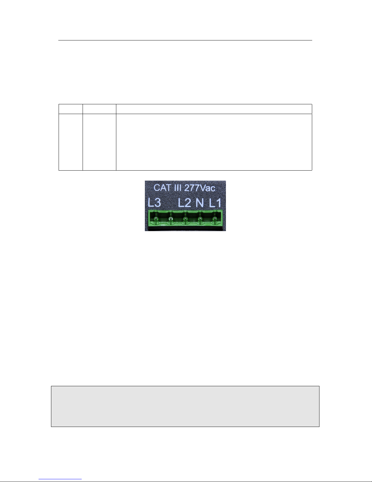
2.7.2 Power Connector
This connector is shown in Figure 2 and the pin-out is as follows:
Pin: Name: Description:
1 L1 Wire to phase 1 of building supply.
2 N Wire to building’s Neutral.
3 L2 Wire to phase 2 of building supply for split- and three-phase
installs.
4 Unused. Leave unconnected.
5 L3 Wire to phase 3 of building supply for three-phase installs.
Figure 2: Power Connector
The Power Connector is CAT III rated (for measurements performed in the building installation, such as circuit breakers). Pin L1 serves three purposes: it powers
the device (2W typical, 7.5W maximum), the voltage on the line is measured
to calculate power used/generated on phase L1, and on model EG301x devices it
carries the power-line signal for communicating with the HomePlug AV wall-plug
adapter. The pin must be wired to the building’s power supply with a voltage in
the range from 85–277Vrms (to neutral). In contrast, pins L2 and L3 are used
purely as voltage-taps so power used/generated on phases L2 and L3 can be calculated. Wiring these pins is necessary only if there are CTs measuring current(s)
on L2/L3. The voltage on these lines can be 0-277Vrms (Vac or Vdc). The input
impedance for L2 and L3 is approximately 950kΩ at 60Hz. By connecting L2 or
L3 to a DC-voltage, it becomes possible to monitor, for example, the voltage on a
battery backup.
CAUTION: Note that L1, L2, and L3 are all coupled to Neutral. Thus, when
using L2 and/or L3 to monitor, e.g., the voltage on a backup-battery, ensure
that it is safe to wire the other pole of the battery to Neutral (pin N).
7 November 3, 2016
EG30xx Owner’s Manual 2 INSTALLATION
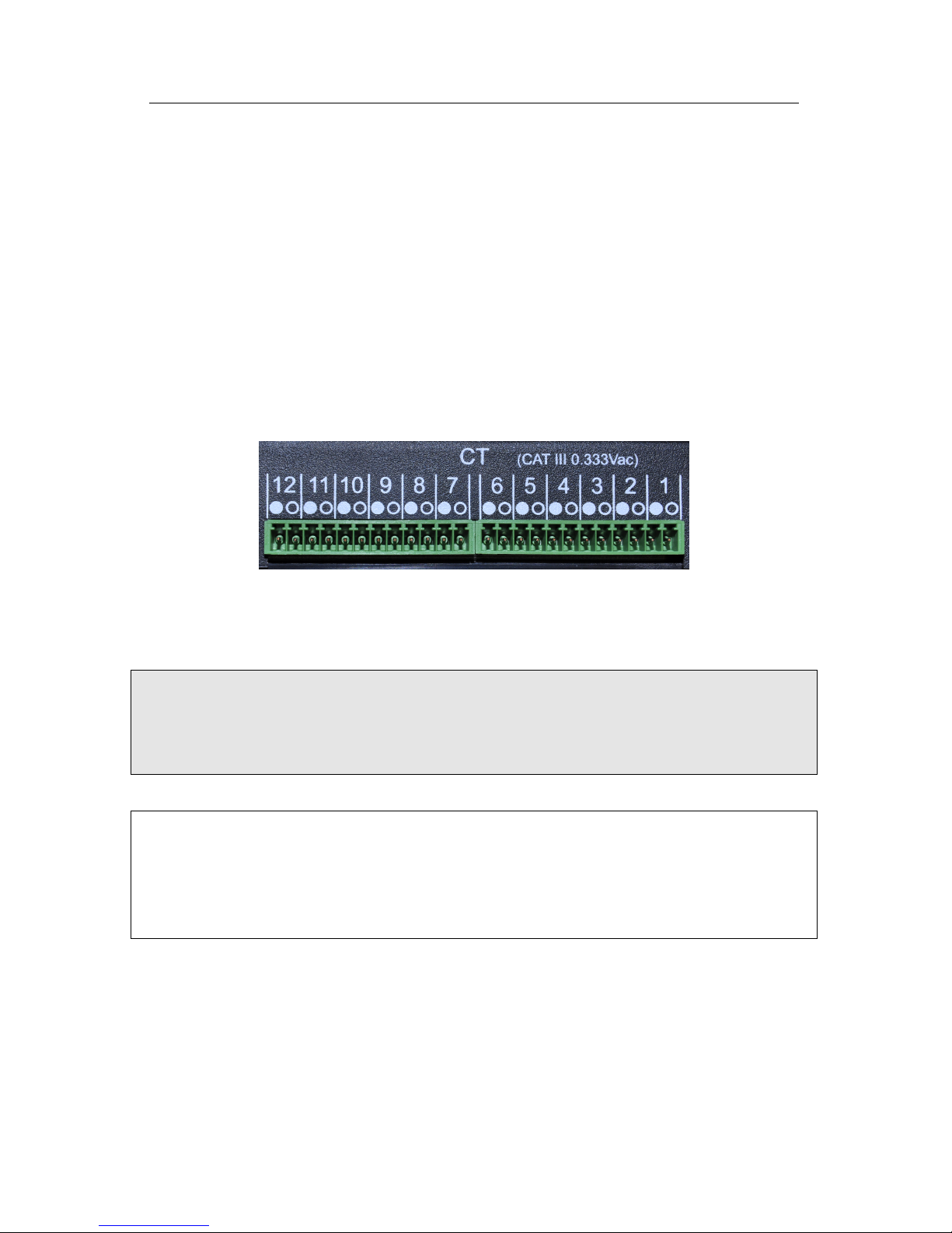
2.7.3 CT Connector
This connector is shown in Figure 3. It provides 12 positions for the CT plugs
illustrated in Figure 7. The silk-screened numbers indicate which CT should be
connected to which pair of pins. Pins that are to receive the black wire of the CTs
are marked with a circle with black interior, pins for the white wires are marked
with a circle with white interior.
The CT Connector is rated for wiring one to twelve units of the CTs listed in
Section B.6. The input voltage rating is 0.333Vrms at the rated current. The input
impedance is approximately 10kΩ at 60Hz.
Figure 3: CT Connector
CAUTION: The pins of the CT Connector are at a potential of 2.5V relative
to Neutral (pin N on the Power Connector). Do not connect these pins to any
of the Power Connector pins or the device may be damaged!
NOTE: There is no risk of damage if a CT plug is accidentally inserted such
that it straddles the pins for two different CTs. If this happens, the eGauge will
not be able to measure power properly but otherwise there are no ill effects. To
correct the problem, simply remove and re-insert the plug at the right position.
2.7.4 Ethernet (LAN) Connector
This connector is shown in Figure 4. It provides hard-wired Ethernet connectivity
via an RJ45 plug.
November 3, 2016 8
 Loading...