

Page 1
IMPACT WRENCHES
OPERATING INSTRUCTIONS
GUARANTEE ........................ 21
COD.79902
COD.79903
Page 2
2
ENGLISH
SIGNAL WORD AND SYMBOL DEFINITION
The signal words and symbols used in the technical documentation (safety instructions, operating booklet, etc.)
have the following meaning:
This symbol
has the
following
meaning:
DANGER
Indicates an immediate danger, which causes serious injuries to any person or even death, if not
avoided.
WARNING
Indicates a threatening danger, which can cause serious injuries to any person or even death, if not
avoided.
CAUTION
Indicates a danger or unsafe procedure which can cause injuries to any person or material damages,
if not avoided.
NOTICE
Indicates a potentially dangerous situation which can cause damage to the product or its
surroundings, if not avoided.
WARNING – explosive atmosphere
Air and ammable substances can mix and result in an explosive atmosphere. In areas
exposed to explosion hazards, supplementary instructions and directives apply. Observe the safety
instructions of the owner as well.
WARNING – explosive material
Caution should be exercised when working with explosive material or in its surrounding area.
PROHIBITION – No naked ame, re, or ignition source and no smoking
Prevent from re and explosion hazards, which can be caused by naked ame, open ignition source or
by smoking.
Eating and drinking forbidden – The prohibition sign forbids the consumption of food.
REQUIREMENT – Observe the instruction
Ensure that the operation process is adhered to and avoid accidents and expensive down times due to
improper use of machines, devices and tools. By using the mandatory sign you refer to the adherence
of operation instructions.
Page 3
3
This symbol
has the
following
meaning:
NOTICE – Gives recommendations and important hints for handling the product
IMPORTANT – Indicates application advice and other particularly useful information.
REMARK:
In each case the symbol used does not replace the safety text. The text must always be read fully. In
some cases other symbols will be used with the signal words.
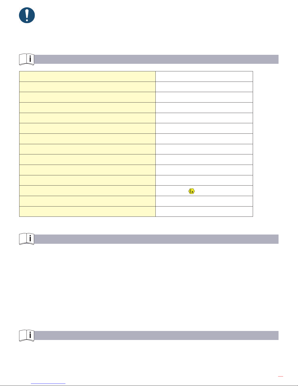
TECHNICAL SPECIFICATION
Operating pressure 6 bar
Drive square 1”
For screws up to M30
Torque 880 Nm
Max. Torque (hard thread) 1350 Nm
Air connection R 1/2“ female
Air consumption in average 1.4 m³/min
Weight 5.7kg
Noise pressure level L
pA
(1)
96 dB (A)
Noise power level L
WA
107 dB (A)
Vibration
(2)
4,5 m/s
2
ATEX Classication
II 2G c T6
(1)
Remark: Measurement acc. to DIN EN ISO 15744 Measurement uncertainty K: 3 dB (A)
(2)
Remark: Measurement acc. to DIN EN ISO 28927-2 Measurement uncertainty K: 1.5 m/s
2
The performance specications are guide values only, they depend basically on the application, the working
pressure and the accessories used.
INTENDED USE
The manufacturer machines are designed for industrial use only.
Only trained, skilled personnel are allowed to operate the machine. Impact wrenches are designed for the
tightening and loosening of screw joints in a range of performance dened by the manufacturer.
They have to be used in combination with appropriate:
• Power socket wrenches,
• extensions,
• joints,
• adapters.
It can be applied for:
• Construction, pipeline construction, chemical industry/reneries and oshore, as well as for underwater use.
IMPROPER USE
Any use deviating from the intended use as described is considered to be improper use.
• Working without personal protection equipment.
• Using the machine in an inadmissable area.
• Using the machine for drilling, mixing or grinding.
Page 4
4
PRODUCT DESCRIPTION
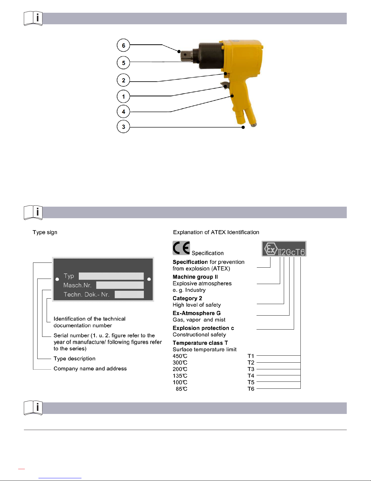
Fig. 1
1 Valve trigger
2 Reverse slide
3 Air connection/ Exhaust
4 Motor housing with pistol grip
5 Impact mechanism housing
6 Drive square
IDENTIFICATION
INSTALLATION
Requirements to the air supply
The pneumatic impact wrench works optimally at an operating pressure of 6(4) bar, measured at the air inlet.
The distance from the air supply to the pneumatic impact wrench should not be longer than 5 m.
We recommend installing an oiler or a maintenance unit upstream the machine for compressed air
preparation.
Page 5
5
Use acid and resin-free lubricating oil, like SAE 5W - SAE 10W, for proper functioning of the pneumatic impact
wrench.
Attention! Do not use viscous oil.
Use an antifreeze lubricant, e.g.:
. “BP-Energol AX 10”,
. “Kilfrost” ,
. or “Kompranol N74” in winter and if the compressed air is very moist.
The supplied compressed air has to be free of:
. Foreign particles,
. humidity.
Pay attention that all hoses:
. Have a cross section being large enough,
. do not have any restrictions or kinks,
. are designed for a minimum operating pressure of 6 bar,
. are replaced regularly at preventative maintenance,
. have an oil resistant inner surface and an abrasion-resistant outer surface,
. are proved and specied to be non-conductive when being used next to electric conductors.
Always use hoses, lubricating oil and antifreeze lubricants, which meet the local safety requirements for use
in areas exposed to explosion hazards.
Connecting the air supply to the pneumatic impact wrench
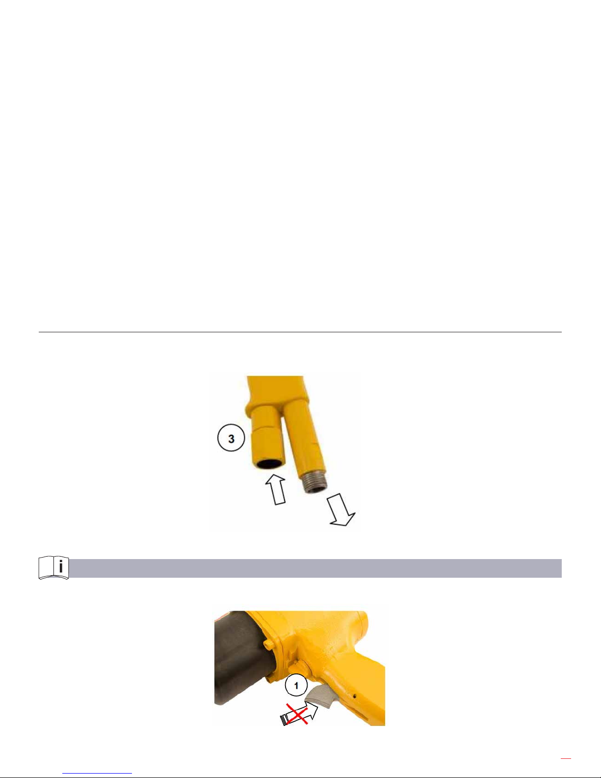
Remove the locking cap from the air connection (see g. 2). Connect the pneumatic hose (not contained in the
scope of delivery). For underwater applications, additionally screw-on an exhaust hose (not contained in the scope
of delivery). Instead of the exhaust hose, an exhaust nipple can be screwed in optionally.
Exhaust
Air inlet
Fig. 2
STARTUP
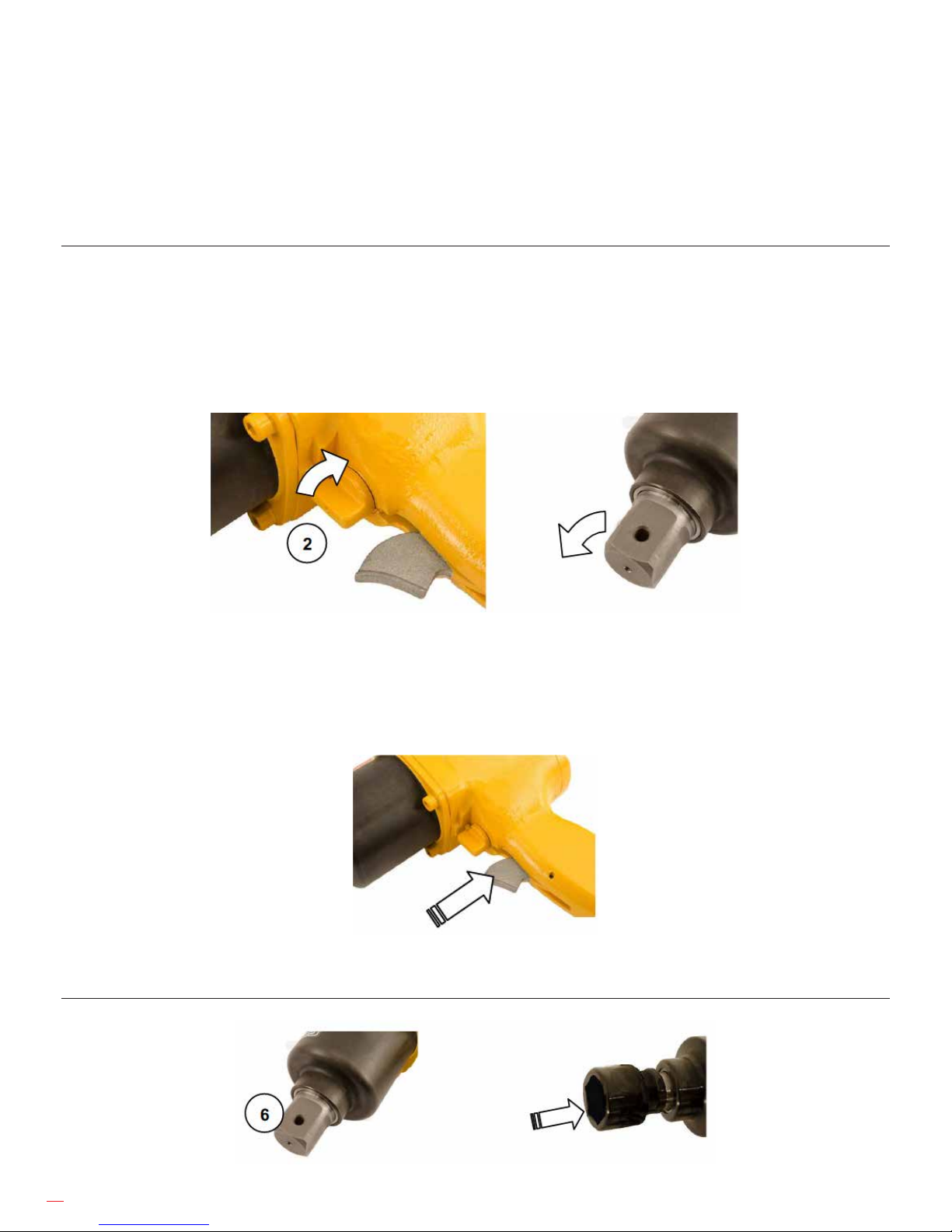
When connecting the machine, pay attention that the valve trigger 1 (see g. 3) is not actuated.
Fig.3
Page 6
6
Blow out the pneumatic hose bevor connecting the machine.
Never connect a pneumatic hose being under pressure (see safety instructions for prevention of hazards caused
by compressed air). First connect the machine and then connect the compressed air supply.
Prior to starting the machine put the reverse slide for rotation direction left and right into the correct position.
For example, if you want to loosen a screw and the rotation direction is adjusted to a position for screwing in, this
can lead to violent uncontrolled movement of the pneumatic impact wrench.
Setting the rotation direction
The rotation direction is set with the reverse slide 2 (see g. 4).
Actuate the reverse slide only when the pneumatic impact wrench is switched o.
Rotation direction right: For screwing-in of screws and nuts turn the reverse slide clockwise.
Rotation direction left: For unscrewing of screws and nuts turn the reverse slide anticlockwise.
Rotation direction right
Fig. 4
Put the power socket wrench solidly and correctly on the screw head or the nut and start the pneumatic impact
wrench (see g. 5).
Start and stop
Fig. 5 Press or release
Insert tool
Slide the socket over the square drive (see g. 6).
Fig. 6
Page 7

7
Pay attention that the socket is rmly seated.
Only use sockets with suitable shank (see “Technical Specication“).
Remove the socket
Pull the socket from the square.
Sockets being stuck can be loosened by slight beats with a rubber hammer.
Change the sockets
When inserting a socket, pay attention that it is properly seated on the square drive 6. If the socket is not rmly
xed to the square drive, it can unscrew.
UNDERWATER USE
Before underwater operation
Ensure that:
. The exhaust hose is connected and xed at the supply hose,
. The exhaust hose is long enough to protrude above the water. In case of a short exhaust hose (in the
water) a reverse valve is used, so that water cannot get into the machine when plunging with the
machine,
. The machine is tested for leakage and for the functioning of all parts (drilling, blowing, valves, etc.).
Notice: Keep in mind that 10 meter water depth corresponds to 1 bar.
When working in greater depths match the diameter of the supply and exhaust hose appropriately.
After underwater operation
. Clean and dry the machine with compressed air.
. Spray all moving parts with multi-oil-spray.
BASIC SAFETY INSTRUCTIONS
Read operation instructions/safety instructions!
Before working on or with the tool, read the safety instructions and follow the instructions during operation.
Do not modify the machine or the machine tools and accessories after receipt. Any constructive changes or
modications need the manufacturer`s acceptance and have to be in compliance with the safety instructions. Use
the machine only for its determination. Consider the technical data of the equipment and the ambient temperatures.
Pay attention to labels, restrictions of use and special instruction notes on the machine tools and the machine itself.
Check regularly that the type plate and symbols on the machine are legible. If necessary, contact the manufacturer
to replace them. Only operators with technical knowledge, trained by authorized responsible technical personnel,
may install, adjust, operate, transport and store the machine.
EMPLOYER’S OBLIGATIONS
Generally, the employer is responsible for the faultless condition/operation of the machine and the adherence to
the safety regulations. The machine is designed and manufactured according to the technical safety regulations.
However, using it, there is still a risk of accidents to the operator or third parties or damage to the machine or
other objects. All current regulations and specications, which apply to the site of operation in regards to accident
prevention, installation of electrical and mechanical systems as well as radio interference must be considered.
IMPORTANT - The employer must make sure that...
• risk assessment is carried out for the specic risks, which can occur due to any operation of the machine,
• the function of the safety equipment is regularly checked,
Page 8
8
• the safety symbols and safety notes on the machine/ device and the operating instruction booklet are
considered,
• the safety instructions and the operating instruction booklet are available completely and in legible condition
on site with the machine.
The employer is obliged to allow personnel to work on the machine only, who:
• Are familiar with the basic work environment safety rules and accident preventing regulations. Also, those
persons must have been instructed in the correct use of the machine,
• have read and understood the safety and warning notes in the operating instruction booklet as well as all the
other documentation pertaining to the machine,
• have been tested at regular intervals in regards to their safety-conscious operation.
Safety-conscious working
Additionally to the safety instructions in this manual and the intended use, the following safety regulations have to
be considered:
• Accident prevention instructions, safety and operation regulations,
• explosion protection directives,
• safety regulations for the operation with hazardous material,
• eective norms and laws.
OPERATOR’S OBLIGATIONS
All persons who are assigned to work with the machine are obligated to:
• Pay always attention to the basic safety and accident preventing regulations,
• read always and follow the safety and warning notes in the operating instruction booklet.
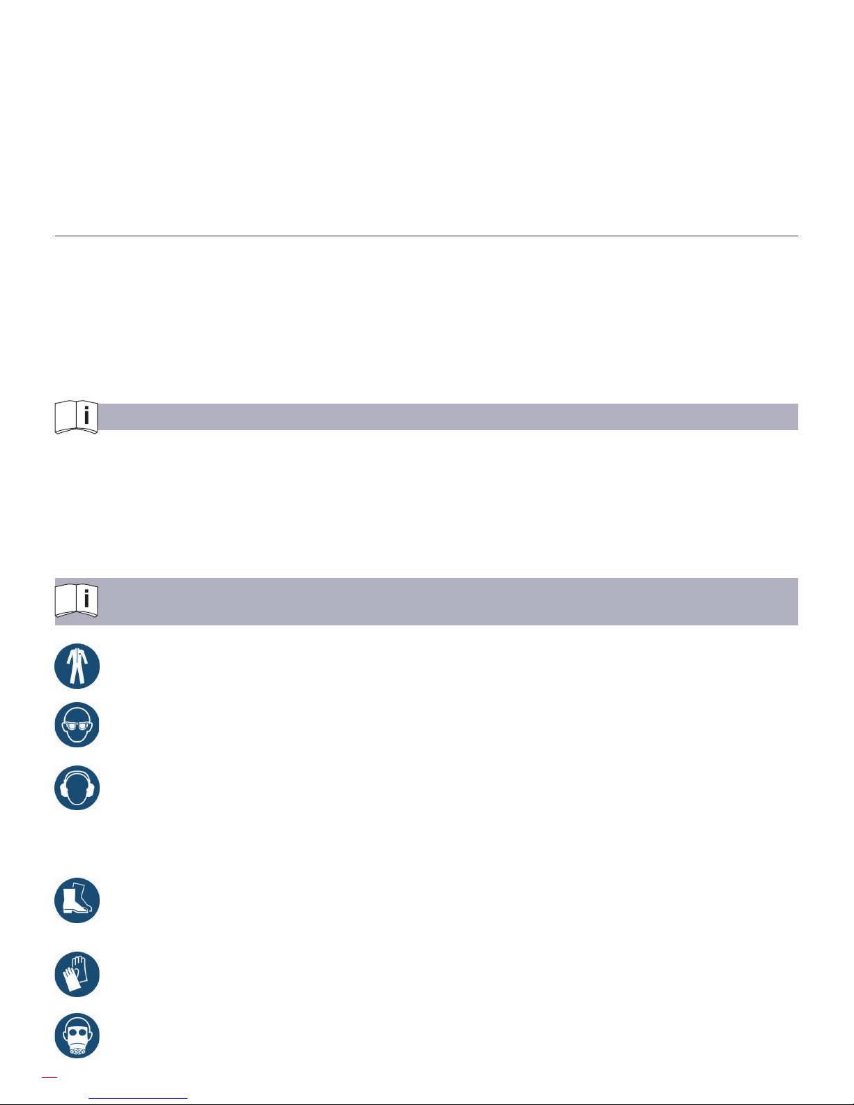
EXPLANATION OF SYMBOLS FOR PROTECTIVE EQUIPMENT
AND FOR ACCIDENT PREVENTION
Use protective clothes – Protective clothes are necessary for diverse applications, e.g.
protection against chemicals, heat and cold. Provide appropriate protective clothes to your sta and
identify this requirement by convincing signage.
Use eye protection – whether goggles, laser safety goggles or etc. – identify areas where eye
protection has to be used, by appropriate mandatory signs.
Use ear protection – Capsule hearing protectors or hearing protectors have to be used for ear
protection, depending on the sound intensity at the work place.
Provide appropriate ear protection and identify the obligation for using ear protection by appropriate
mandatory signs.
Use foot protection – Foot injuries by vehicles, objects, hot material or hazardous
substances can be avoided by appropriate protective shoes. Equip your sta with
appropriate protective shoes and identify those requirements properly.
Use hand protection – Identify convincingly the safety requirement “Use hand protection“ by a gloves
sign, respectively a gloves symbol.
Use respiratory protection – Ensure that the specied protection equipment is available and that it is
used. Identify by mandatory signs, where and when respiratory masks are required.
Page 9
9
Danger Zones
Operational
condition
----------------------Life phase
Normal function Malfunction Improper use Expected use
Transport
Transport of
the machine
in inoperable
condition
Drop of the
machine
Transport of
the machine in
operable condition
unknown
Startup
Equipment of
the machine with
designated socket
unknown
Equip the machine
with other tools
unknown
Operation
Machine works
only with actuated
valve
Machine runs
without intended
actuation
Valve is blocked in
actuated condition
unknown
Machine moves
the socket
Machine does not
move the socket
unknown
Maintenance
Operation at
a service unit
Regular cleaning
Breakdown of the
machine
unknown unknown
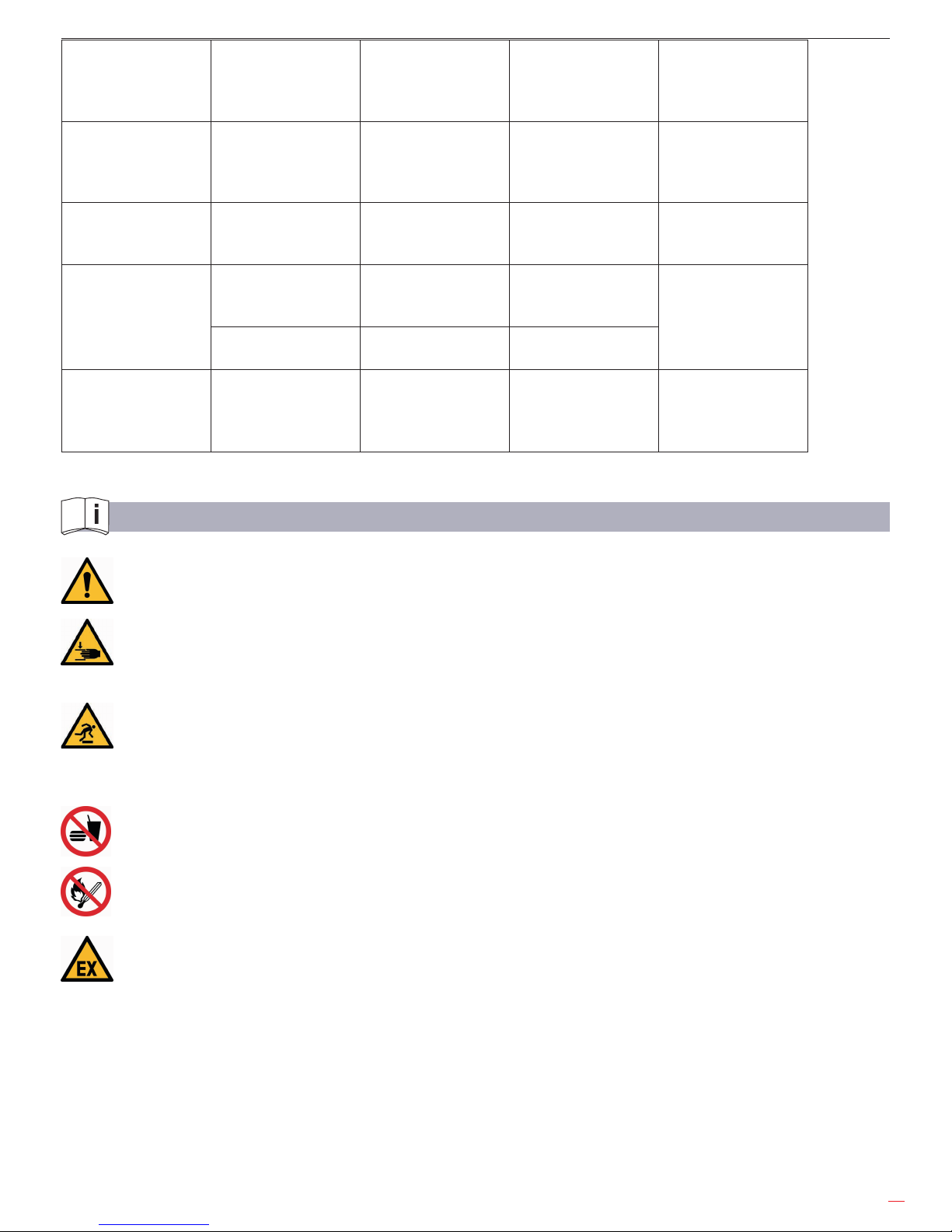
SAFETY INSTRUCTIONS FOR PREVENTION OF WORKPLACE HAZARDS
WARNING
The following applies unless otherwise stated in the machine’s operating instructions booklet:
The machine is not insulated to protect against an electrical power surge.
CAUTION – risk of injury!
Hands may be crushed, seized or otherwise injured.
Keep your hands away from areas which are marked with this symbol.
CAUTION – risk of injury!
Remove all sources of danger which could lead to slipping, tripping or falling (e.g. slippery surface,
hoses, cables).
Keep the work area clean and dry.
PROHIBITION – Eating, drinking and smoking are forbidden during operation.
WARNING – Explosion hazard!
Operate the machine according to the intended use only.
The machine is designed for the use in areas exposed to explosion hazards as well.
Observe the following:
· Valid local explosion protection directives.
· Technical specication of the machine.
· Markings on the machine.
· Avoid the generation of sparks.
· When operating the machine, do not push or beat against other material and hold the machine
rmly and safely by hand.
· Do not slide the machine over the ground.
Page 10
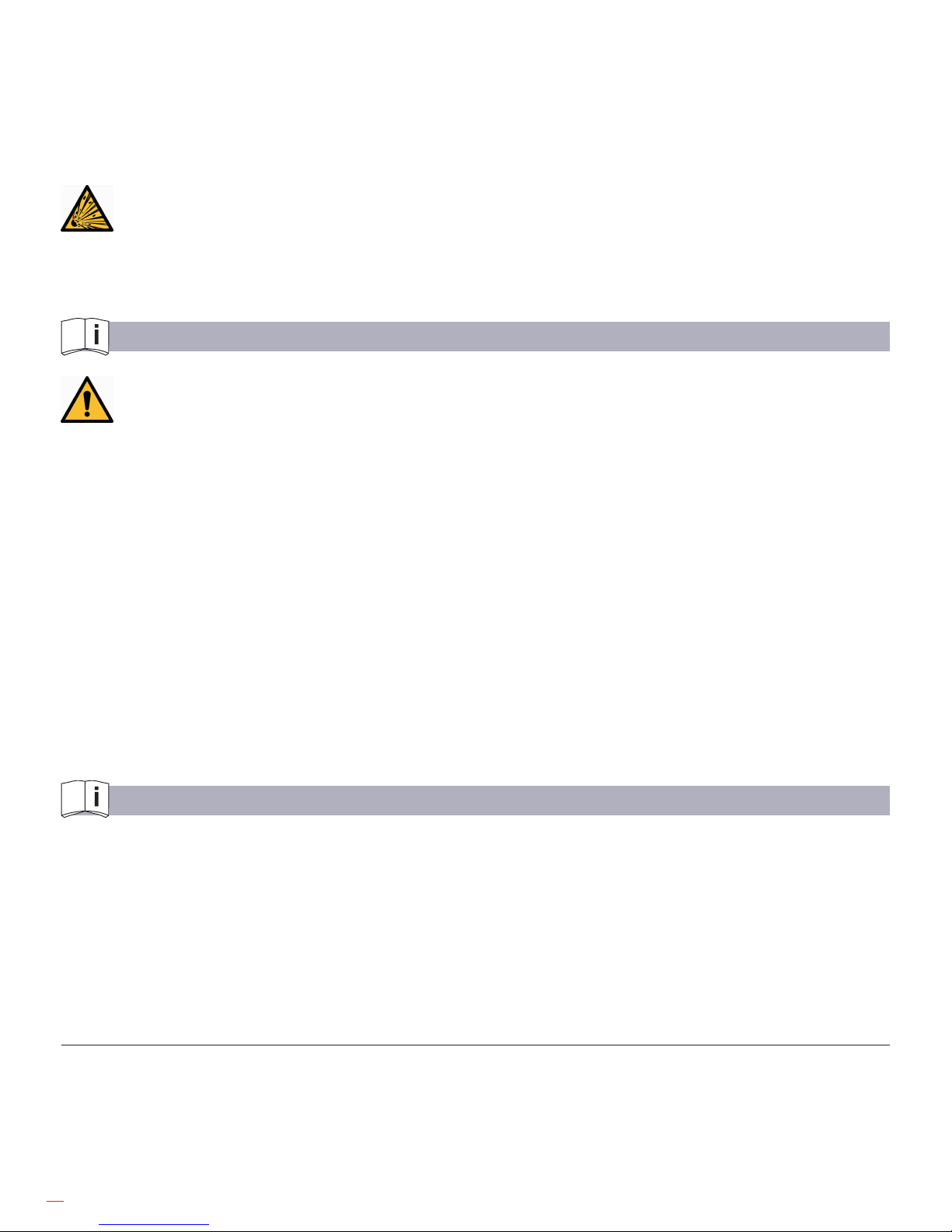
10
· If heat generation exceeds the specied surface temperature, the machine has to be stopped
instantly. It only may be re-started after having eliminated the cause for the fault.
· The work area and the next working areas should always be protected from sparks.
· Flammable and explosible material has to be removed from the work area before work is started.
Among others, this relates to dust deposits, cardboard, packing material, textile, wood and wooden
splints, but also ammable uids and gas.
Ensure adequate lighting.
Be extra careful in unfamiliar surroundings. There is a risk of hidden hazards such as electric lines or
other supply lines. Make sure when operating the machine that no electrical cables, gas pipes or similar
could be damaged. Use suitable and personal protective equipment.
SAFETY INSTRUCTIONS FOR PREVENTION OF HAZARDS CAUSED BY COMPRESSED AIR
WARNING – Compressed can cause severe injury. Before working on the tools (e.g.
installation, changing accessories or machine tools, prior to a long standstill, maintenance, etc.)
depressurize pneumatic equipment.
CAUTION – Risk of injury by whipping pneumatic hose.
Check pneumatic hoses, connection components and ttings regularly for any damages and proper
xture.
When connecting / disconnecting the machine to / from the pneumatic supply, please pay careful attention not to
actuate the valve while doing so. Never remove a pressurized pneumatic hose. Always switch the power supply o
rst and then depressurize the machine.
The maximum operating pressure (fow pressure) according to the technical specication must not be
exceeded. A pressure regulator should be installed, which regulates the pressure before it reaches the
machine. Never direct a pneumatic hose at yourself or anyone else. Never clean your clothes with
compressed air. Direct cold air away from your hands. Do not pull or carry the machine by the pneumatic
hose. When using claw couplings make sure that they are tted with a suitable lock mechanism (e. g. lock
pin) and a safety chain.
SAFETY INSTRUCTIONS FOR PREVENTION OF OPERATING HAZARDS
Before starting work make sure that the hands are protected against:
impacts, crushing, hits, cuts, abrasions and heat. The operating and maintenance personnel must be physically
able to handle the bulk, the weight, the power and/or the torque of the machine.
Do not use the machine if you have taken any medication or drugs, after drinking alcohol or with any other
constraints on your vision, reaction time or judgment.
Work in the best possible position so that you can react with both hands to any normal or unexpected movements
of the machine. Maintain a balanced body position and secure footing in order to avoid improper strain and to be
able to support the reaction torque of the machine).
Additionally observe the following:
• Operate the machine only after having carefully read the operation manual.
• Use impact wrenches only in combination with appropriate power sockets.
• Never use power sockets with worn out square drive. Prior to each application, check that the square drive
at the power socket and the square drive of the impact wrench is not worn out, or if there are any ssures (cracks).
Ensure that the power socket is properly seated on the square drive before each startup.
• Before each startup, ensure that the reverse valve for rotation direction left and right is in the correct position.
Do not start the machine, unless the power socket is seated solidly and correctly on the screw head or on the nut.
Page 11
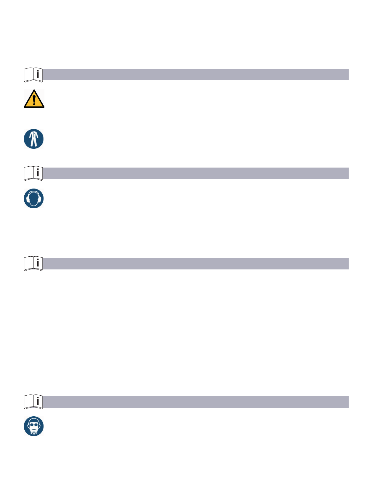
11
• Do not hold or guide the machine at the turning power socket.
• Consider enough space behind you when loosening screw connections, so that the operating hand cannot
be jammed.
• Use only extensions, adapters and joints, which are explicitly approved for the application with impact
wrenches.
• If the machine shows any signs of abnormal operation or performance, work must be stopped instantly for
maintenance and repair.
SAFETY INSTRUCTIONS FOR PREVENTION OF ENTANGLEMENT HAZARDS
CAUTION – Loose clothing, personal jewellery (e.g. necklace), scarves/ ties, long hair or gloves can
get caught up in the machine tool or accessories and thus cause severe injuries (lack of breath by
throttling, abrasions, skin injuries and/ or cuts and lacerations)
Wear suitable, close tting work clothing!
Wear a hair net, if you have long hair.
When handling the machine, jewellery, necklaces, etc. have to be removed or are forbidden,
respectively.
SAFETY INSTRUCTIONS FOR PREVENTION OF NOISE HAZARDS
Always wear hearing protection – This refers to the operator, as well as to any other person within
the vicinity of the machine. Observe the instructions of the employer and of the professional
association.
During operation high noise levels can cause permanent hearing problems such as tinnitus (ringing, buzzing,
whistling or humming in the ears), hardness of hearing or even deafness.
• If possible, use sound absorbing material, in order to avoid ringing noise at the work pieces.
SAFETY INSTRUCTIONS FOR PREVENTION OF VIBRATION HAZARDS
Vibrations can cause damage of nerves and blood vasculares in hands and arms, therefore observe the following
hints:
· Wear warm clothing and keep your hands warm and dry when working in cold conditions. Exercise hands and
ngers regularly.
· Do not hold the machine tool with the free hand
· Use stands and/or weight balancers, if possible.
· When using a support (e.g. stand) make sure the machine is securely xed. If no support is used, hold the
machine with light but safe grip in order to support the tool’s reaction torque. The tighter the grip the greater the risk
from vibrations.
· Mount the machine as described in the operating instruction booklet in order to avoid unnecessary high
vibrations.
· Stop work immediately, if you feel any numbness, tingling, pain or whitening of ngers or hands. Inform the
employer and consult a doctor.
SAFETY INSTRUCTIONS FOR PREVENTION OF DUST AND FUME HAZARDS
Wear respiratory protection.
Use respiratory protection as instructed by your employer and as required by occupational health and safety
regulations.
Potentially generated or disturbed dust and fumes in the working environment or from using the machine
can cause ill health (e.g. cancer, birth defects, asthma and/ or dermatitis).
Page 12
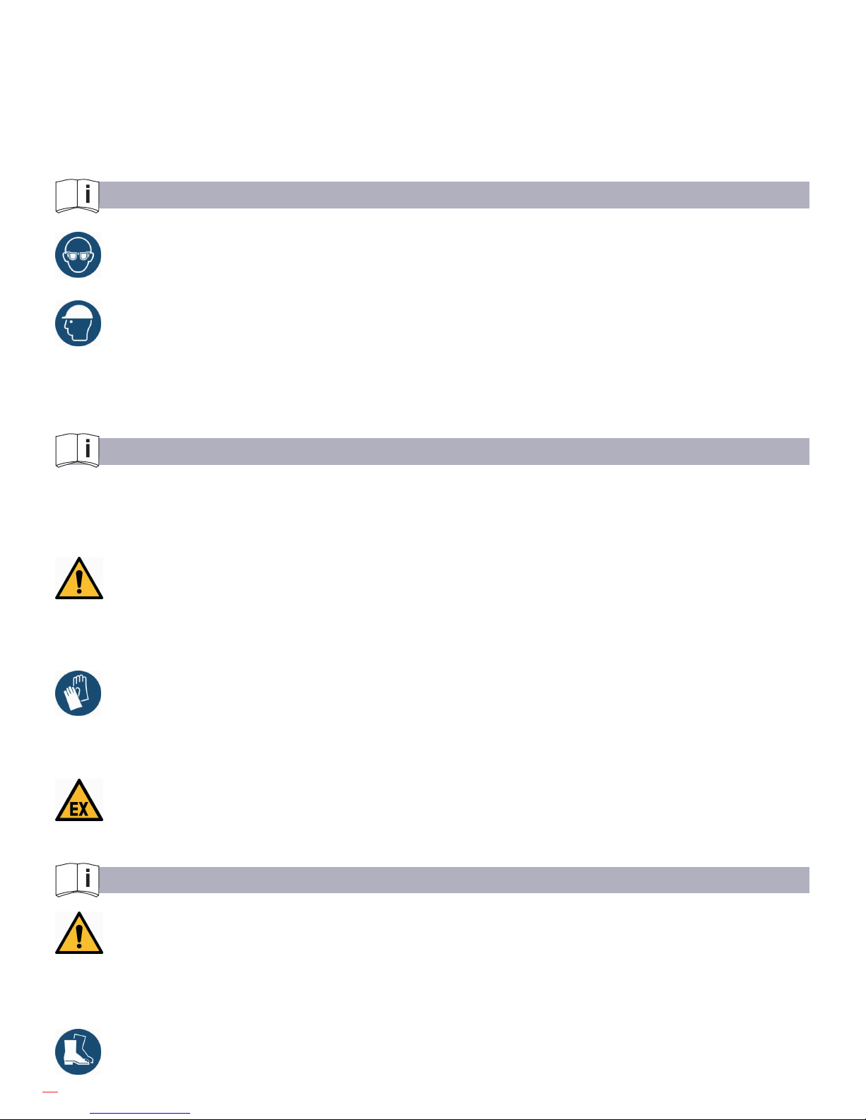
12
· Carry out risk assessment regarding dust and fume hazards and implement appropriate measures.
· Keep the working place clean.
· Keep in mind that working in certain materials may create dust and fumes causing a potentially explosive
atmosphere.
Remark: Some types of metal may have toxic coatings.
Please pay particular attention to avoid skin contact and breathing in, when working with those materials. Ask
your material supplier about special safety instructions and stick to them.
SAFETY INSTRUCTIONS FOR PREVENTION OF PROJECTILE HAZARDS
Wear impact-resistant safety goggles – This refers to the operator, as well as for the persons within the
vicinity of the machine. Assess and determine the grade of protection required depending on the individual
case. The risks to others should also be assessed at this time.
On overhead work, wear a safety helmet. If a work piece, accessories, inserted tools, or the tool itself
breaks, there is danger from high velocity projectiles.
· • Check all parts for damages before using the machine.
• Replace damaged parts immediately.
• When working on brittle material make sure that you are protected against harmful splinters.
SAFETY INSTRUCTIONS FOR PREVENTION OF ACCESSORY HAZARDS
Use only machine tools, accessories and consumables, which are recommended by the manufacturer. Make sure
choosing the correct size and the correct type. Use only accessories, which are in proper condition and do not touch
them during operation.
CAUTION – Injury due to carelessness!
If the machine is xed to suspension equipment make sure that it is secure. Never hang the machine
onto the supply line.
· Separate the machine form any external energy source before changing the machine tool or an
accessory.
· Avoid direct contact with the machine tool during and after use as it can be hot or sharp.
· Wear protective gloves when changing a tool or an accessory!
Notice: Defective/ inappropriate gloves can lead to injury. Only wear proper hand protection, adapted to the work
place requirements.
WARNING – Explosion hazard!
When operating the machine in areas exposed to explosion hazards, use only accessories,
respectively devices, which are ATEX approved and specied.
SAFETY INSTRUCTIONS FOR PREVENTION OF TRANSPORT HAZARDS
ATTENTION – Improper Transport, danger of life due to parts falling down!
Damage of the machine!
· Separate the machine form any external energy source before transportation.
Check that the machine is undamaged and in proper condition.
· Never carry the machine at the supply line.
Wear worker’s protective shoes!
Page 13
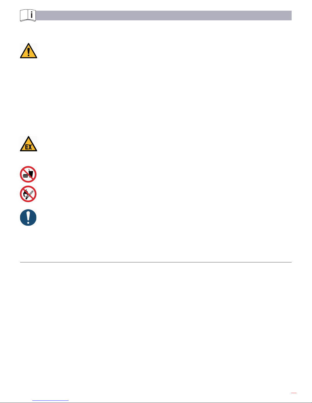
13
SERVICE AND MAINTENANCE
Basic Safety Instructions:
WARNING – Maintenance and repair work on pneumatic equipment.
Compressed air can cause severe injury. Observe legal regulations. Take precautions for persons and
environment.
Additionally, observe the following:
• Secure the machine against unintentional starting and let the machine cool down to the ambient
temperature
• Protection against tipping, tumbling or falling down when assembling/ disassembling the machine/
parts.
CAUTION – Skin exposure to hazardous dusts may cause severe dermatitis. Dust at the work place
can be raised during the maintenance procedure and can be inhaled.
Clean the machine and the work place before maintenance work.
WARNING – Danger of explosion! Generation of sparks during maintenance work!
Consider local safety regulations. Avoid use of force when disassembling and assembling the machine.
Always do maintenance work outside hazardous medium.
PROHIBITION
Eating, drinking and smoking are forbidden during maintenance and repair work.
NOTICE – Only use original the manufacturer, in order to avoid damages. Otherwise you risk a
decrease in machine performance and an increase in maintenance work. Check the adherence to the
technical specications according to the operation manual after each maintenance work.
IMPORTANT – There is no warranty for damages and liability is disclaimed, if non-original spare parts are
used.
Maintenance Instruction
Generally, pneumatic machines need little maintenance. If these rules are followed, the machine will have the
expected durability and high reliability. Service life and performance of the machines are decisively determined by:
• The air purity
• The lubrication conditions and maintenance
• The regular control of the compressed air lter, as well as the regular checking of the machine with regards
to external damages.
Inspection and maintenance can be done by the operator.
Disassembly and re-assembly of the machine have to be executed by qualied sta only. Incorrect assembly can
lead to danger of accident for the operator and to defects on the machine.
Additionally to the measures described before, it is a must to check the grease in the gear and to ll it up or
replace it, if necessary.
The correct quantity of grease (15g) is very important with regard to good lubrication and low warming.
Page 14
14
Furthermore we recommend giving the hidraulyc impact wrench a general overhaul by the supplier once a year.
After completing maintenance and repair work and before restarting production make sure that...
• All materials, tools and other equipment which are required for maintenance or repairs have been removed
from the work area of the machine.
• Any uid leaks have been removed.
• All safety devices on the machine have proper function.
• Fixtures of screw connections are tight
• Removed covers, screens or lters were reinstalled
The employer ensures that all maintenance, inspection and assembly work is done by authorized and qualied
experts.
DISASSEMBLY- RE-ASSEMBLY
Maintenance and repair
Disassembly and re-assembly should be done according to the exploded views, respectively the sectional
drawings (see repair instruction).
All work regarding disassembly and re-assembly, as well as maintenance and repair have to be executed by
skilled sta only.
DANGER – Working with the machine without appropriate preparation and disregarding of instructions.
Shut down the machine properly and let it cool down to the ambient temperature.
NOTICE – Special instructions apply for the repair of explosion-proof machines. Retrots or
modications of the machine need the manufacturer’s acceptance.
The explosion-proof machine is designed in the type of protection “c“ constructive safety.
All work executed on the machine, inuencing the explosion protection, e. g. repairs with mechanical machining,
require an approval of an authorized expert or have to be done by the manufacturer.
The internal structure must remain unmodied.
STORAGE
Unused machines and machine tools should be kept in a dry, closed room.
Keep them free from damaging inuences such as damp, frost or large temperature uctuations as well as
mechanical damage. Always store the machine in a way that important machine instructions, e. g. on stickers and
signs, are legible.
DISPOSAL
Dispose of machine and worn out/defective machine tools according the local/national regulations. Fully
disassemble the machine for the necessary disposal. Separate materials according to local environmental
specications. Dispose of environmentally hazardous greasing, cooling or cleaning agents in order to avoid
environmental contamination.
Page 15
15
ENVIRONMENTAL REGULATIONS
When working on or with the equipment, it is imperative to observe all legal requirements in regards to wastedisposal and proper recycling. In particular during installation, repair and maintenance work, water damaging agents,
such as:
· lubricating grease and oil,
· coolant,
· solvent containing cleaning agents must not leak into the ground or reach the sewage system.
These materials must be stored, transported, contained and disposed of in suitable containers!
TROUBLESHOOTING
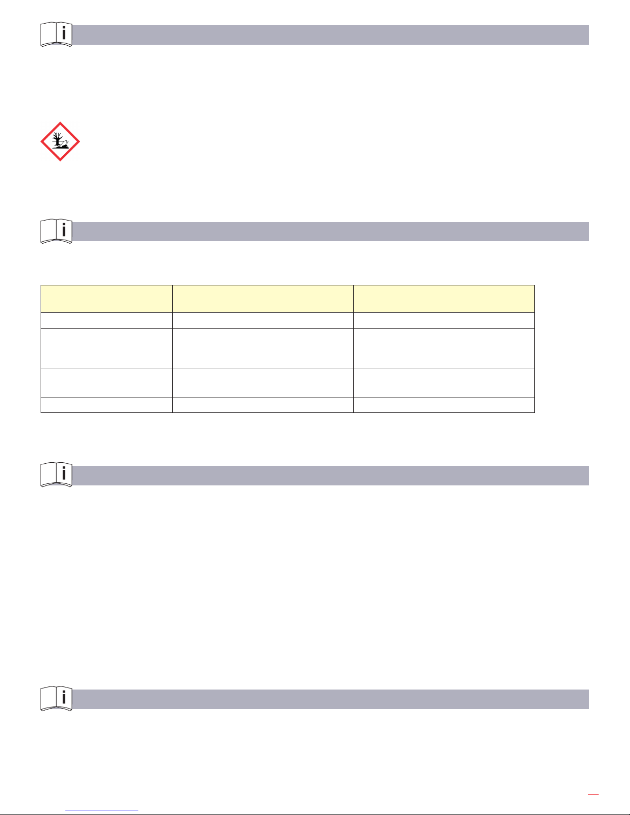
The following table shows possible problems and their causes:
Problem, cause, remedy
Problem Cause Remedy
Machine does not start Not connected to pneumatic supply. Connect and open the neumatic line
Machine is rotating too
slowly
Too little operating pressure
Hose diameter too small
Too little volume ow
Increase operating pressure
Choose larger hose diameter
Increase volume ow
Machine makes strong
noise
- Contact authorized expert company
Other trouble - Contact authorized expert company
We ask you to send the machine to the supplier, if necessary.
WARRANTY AND LIABILITY
Unless otherwise specied, our “General Sales Terms” apply. Warranty and liability claims in regards to persons
or equipment damages are invalid, if one or more of the following causes apply:
• Improper use of the machine,
• improper assembly, startup, operation or maintenance of the machine,
• operation of the machine with defect safety devices or improperly xed or non-functioning safety and
protection devices,
• not considering of the instructions in the operating instruction booklet concerning transport, storage,
assembly, startup, operation, maintenance and setting up of the machine,
• independent structural alterations or settings on the machine beyond the intended purpose,
• inadequate supervision of wear parts,
• improperly carried out repairs, inspections or maintenance,
• catastrophic cases due to foreign objects, acts of god or other reasons which are beyond our control.
SCOPE OF DELIVERY
Check, if the scope of delivery is complete:
1 Operation and maintenance manual,
1 Pneumatic Impact Wrench, Accessories, if applicable.
Page 16
16
REPAIR
Disassembly
Disassembly and re-assembly should only be performed with assistance of the sectional drawing.
Loosen screws item 22 and remove motor housing cover item 20 with sealing item 19 for changing the
vanes. Pull o the end plate item 17 and rotor item 14. Take the vanes item 16 out of the rotor slots. The
slots have to be cleaned from oil and resin residues before installing new vanes. The assembly of the rotor is
done after having cleaned the running surface of the end plates and the cylinder bushing.
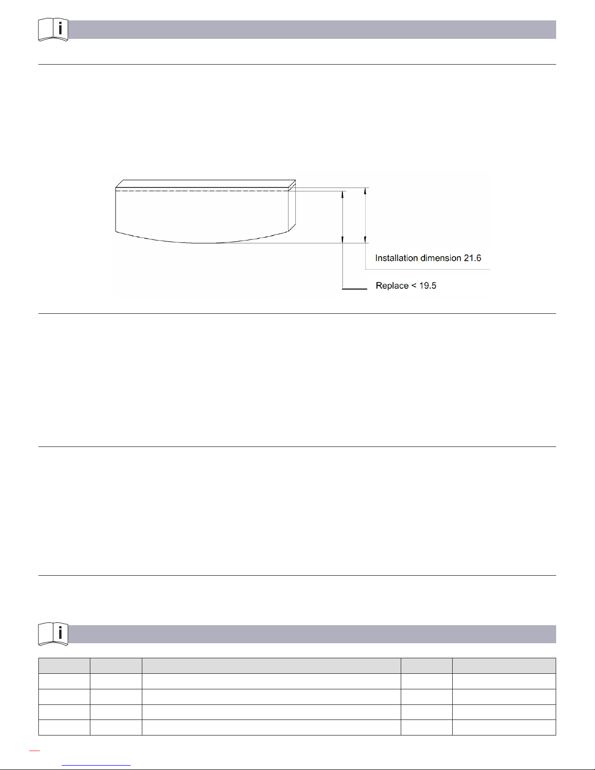
The vanes are considered to be worn, when their width is less than 19.5 mm.
Vane
Complete disassembly
Loosen screws item 58, pull o impact mechanism housing item 51 with complete impact mechanism and
continue disassembling. Remove centring ring item 37.
Remove motor housing cover item 20 after loosening the screws item 22. Take inner motor parts like end plates
item 10 and 17, rotor item 14 and cylinder bushing item 12 with arresting pin item 13 out of the motor housing item
1. Pull the vanes item 16 out of the rotor slots. Press the locking bolt item 15 out of the rotor drillings. Remove the
nipple with screen item 35 from the air connection piece item 4, remove air connection piece, Assy., item 4 and take
out valve pin item 28, screw nipple item 36 out of handle part. Remove pins item 7 and 26 and take out valve trigger
item 25 and pull out reverse slide item 5. Pull out pin item 9 and pressure spring item 8.
Reassembly
The reassembly is basically done in the reverse order than the disassembly. Wear and tear parts -especially the
vanes item 16 –should be replaced in time. They are considered to be worn, when the width is less than 19.5 mm. If
the rotor or the cylinder bushing has been replaced, respectively the plane surface has been nish grinded, the end
play between the rotor and the end plates item 10 and 17 has to be checked. The end play should be 0.05 mm on
each side (the cylinder bushing must be 0.1 mm longer than the rotor
measurement). The xing screws have to be installed with a screw locking, e. g. Loctite 243.
After re-assembly the function and performance of the impact wrench have to be checked.
For this, refer to the technical data of the operation and maintenance instruction.
Spare Parts
Only original spare parts may be used. There is no warranty for damages and liability is disclaimed, if nonoriginal
spare parts and accessories are used.
SPARE PARTS LIST
Item Qty. Description Remarks
Pneumatic Impact Wrench 1“
consisting of:
1
Pneumatic motor with handle
1
Impact mechanism, Assy..
Page 17
17
Page 18

18
Item Qty. Description Remarks
1 Motor housing, Assy. item 1-9
1 1 Motor housing with bushings
2 1 Bushing
3 1 Reverse bushing
4 1 Air connection piece, Assy.
5 1 Reverse valve, Assy. with item 6
6 1 O-Ring *
7 1 Cylinder pin *
8 1 Pressure spring *
9 1 Pin *
10 1 End plate *
11 1 Grooved ball bearing *
12 1 Cylinder bushing *
13 1 Locking pin
14 1 Rotor, Assy.
15 6 Locking bolt
16 6 Vane *
17 1 End plate *
18 1 Groove ball bearing *
20 1 Motor housing cover
21 4 Spring washer
22 4 Socket head screw
25 1 Valve trigger
26 1 Tension pin
28 1 Valve pin *
35 1 Nippel, Assy. *
36 1 Nipple long
37 1 Centring ring
38 1 O-Ring
*
Page 19

19
Page 20
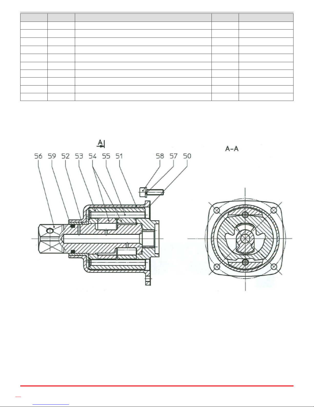
20
Impact Mechanism
Item Qty. Description Remarks
50 1 Sealing *
51 1 Impact mechanism housing, Assy.
52 1 Guide bushing *
53 1 Cross bar
54 2 Hammer
55 2 Bolt *
56 1 Anvil 1“ *
57 4 Spring washer
58 4 Socket head screw
59 1 Quad-Ring *
* Wear parts to be stored in case of continuous use.
Page 21
Page 22

Page 23

Page 24
C/ ZORROLLETA 11, POL. IND. JUNDIZ
01015 VITORIA, SPAIN P.O.B. APTDO. 5005
TEL. 34 - 945 290 001
FAX. 34 - 945 290 141
www.egamaster.com
 Loading...