

Ega Master CURVAMATIC-2, 60015 Operating Instructions Manual
MANUAL DE INSTRUCCIONES
OPERATING INSTRUCTIONS
MANUEL D’INSTRUCTIONS
MANUAL DE INSTRUÇÕES
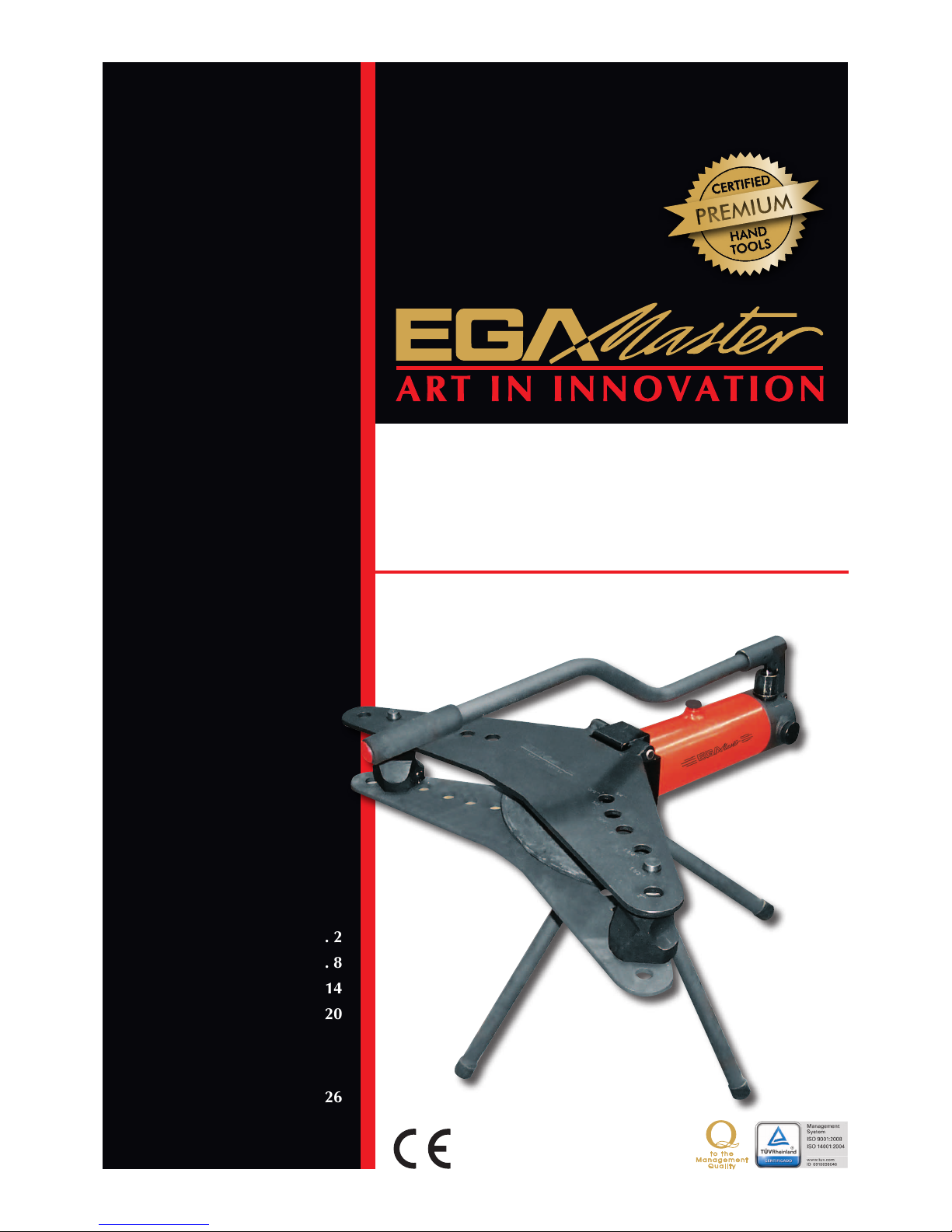
CURVAMATIC-2
CURVATUBOS HIDRÁULICO / HIDRÁULIC
PIPE BENDER / CINTREUSE HYDRAULIQUE /
CURVADOR DE TUBOS HIDRÁULICO
ESPAÑOL ............................... 2
ENGLISH ................................ 8
FRANÇAIS ............................ 14
PORTUGUÊS........................ 20
DESPIECE / SPARE PARTS
DRAWING / DEPEÇAGE /
DESENHO DAS PEÇAS
SOBRESSALENTES ................ 26
GARANTIA / GUARANTEE /
GARANTIE ........................... 29
COD. 60015
2
INSTRUCCIONES DE SEGURIDAD
¡Atención! Cuide su seguridad.
1. No utilice prendas colgantes que se puedan enganchar en los elementos en movimiento .
2. Utilice siempre guantes.
3. Emplee siempre los accesorios destinados a la máquina ya que sin su utilización puede resultar
lesionado.
4.
No manipular ni utilizar la máquina desde la zona delantera (zona de curvado de tubo). El usuario
siempre se debe situar en la zona trasera (zona del pistón hidráulico).
5. Colocar siempre la pata delantera perfectamente alineada con el pistón hidráulico para garantizar
la seguridad durante el uso.
CURVATUBOS HIDRÁULICO – 2
Máquina curvadora adecuadamente equipada para curvar tubería de acero para conducción de
agua, gas, etc. de ¼"÷2". Su sistema de dos velocidades permite de forma automática una rápida
aproximación, así como un suave doblado sin necesidad de cambiar de pistón. Dispuesta con
doble placa, lo que le da la máxima consistencia durante el curvado. Asentamiento sobre 3 patas
de apoyo para obtener una mayor estabilidad.
- Sistema de giro del cilindro y placas para poder curvar en zonas de dicil acceso.
- Sistema de bloqueo del cilindro para una mejor estabilidad en el proceso de curvado.
Este curvatubos está diseñado para curvar tubos conformes a la norma DIN-2440, y que hayan
sido conformados en caliente. Se muestra una tabla con los diametros y espesores que dicta la
norma DIN-2440.
Presión de trabajo: 10 Tm.
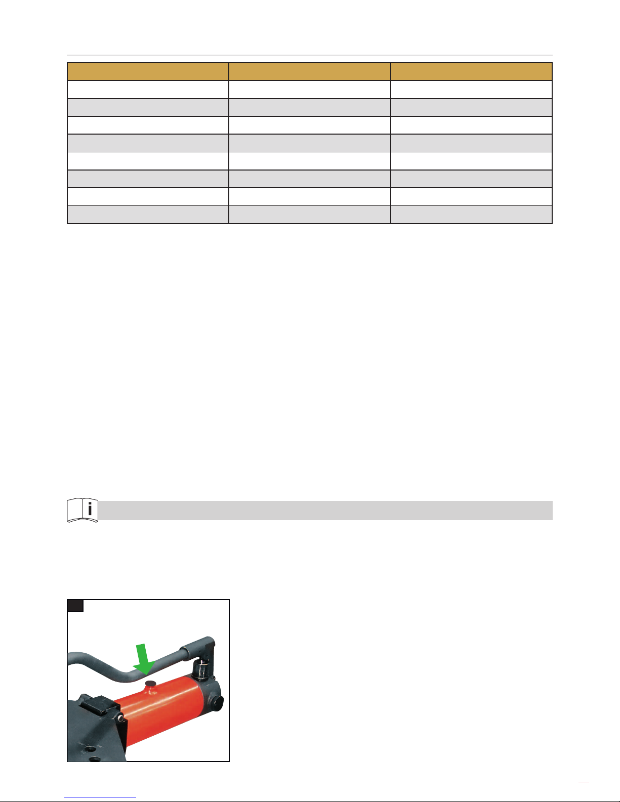
ATENCIÓN
Antes de comenzar a trabajar, aojar ligeramente (una vuelta) el tornillo de llenado de aceite nº36.
ESPAÑOL
3
TABLA DE DIAMETROS DE TUBOS DIN-2440
TAMAÑO DIAMETRO EXTERIOR ESPESOR
1/4 13,5 2,35
3/8 17,2 2,35
1/2 21,3 2,65
3/4 26,9 2,65
1 33,7 3,25
1.1/4 42,4 3,25
1.1/2 48,3 3,65
2 60,3 3,65
MANTENIMIENTO
Es importante utilizar aceite hidráulico. No utilizar ningún otro tipo de uído.
Filtrar el aceite antes de introducirlo en el depósito. Cualquier elemento extraño podría dañarlo.
En posición de reposo la válvula (nº50) debe estar abierta y el pistón debe estar retirado para
evitar que el muelle de retorno del pistón se encuentre presionado.
Después de varios dias sin uso deben engrasar la extremidad que asoma del pistón para evitar
oxidaciones y agarrotamientos al utilizarlo de nuevo.
RECOMENDACIONES
No ponerse nunca delante de la máquina, evitaremos accidentes.
IMPORTANTE
Para el pedido de repuestos indique el código de éstos y el número de serie de la máquina.
INSTRUCCIONES DE FUNCIONAMIENTO
A) LLENADO DEL DEPÓSITO
Introducir aceite a través del tapón (nº36). Para ello, se aconseja retroceder completamente
el pistón (mediante la ruleta de retroceso), estabilizar en horizontal el pistón para nivelar
completamente el aceite, meter una varilla hasta encontrar un obstáculo y medir 1,5cm de aceite.
Ese será el nivel ideal de llenado.
A
4
B) CURVADO DE TUBOS
B1. El tornillo superior de llenado de aceite debe estar parcialmente abierto para el uso. Sólo debe
cerrarse para el transporte.
B2. Cierre la válvula (nº50).
B3. Con la placa superior abatida, coloque ambos diábolos en sus correspondientes alojamientos
de la placa inferior según la medida del tubo a curvar.
B4. Seleccione la huella correspondiente del diábolo y orientelo hacia la máquina.
B5. Seleccione la galleta necesaria en función de la medida del tubo a curvar.
B6. Introduzca el tubo a curvar alojándolo entre la galleta y los diábolos.
B7. Bloquear el eje giratorio para mayor estabilidad en el proceso de curvado. Apretar prisionero
para jar la posición del cilindro. Aojar prisionero para dejar libre el giro del cilindro.
B8. Introducir y accionar la palanca en el alojamiento del pistón e iniciaremos el movimiento
rápido de salida del pistón hasta que la galleta haga contacto con el tubo. En ese instante se
accionará la velocidad de curvado suave, que nos permitirá curvar con mínimo esfuerzo.
B9.
Una vez realizado el curvado, se abrirá la válvula (nº50). El pistón retrocederá automáticamente.
B10. Eleve la placa superior y retire la galleta junto con el tubo curvado.
B1 B2 B3
B4 B6
B5
B7
B8 B10B9
nº50
5
SOLUCIÓN A POSIBLES ERRORES
a) El pistón no avanza: compruebe que el tornillo superior (Fig.B1) está parcialmente abierto y que
la válvula de retorno (nº50) está cerrada.
b) El pistón no retrocede o no retrocede completamente: compruebe que el tubo no está atascado
en los émbolos laterales. Dando un suave golpe debería soltarse. Comprobar también que el
tornillo superior (Fig. B1) no esté cerrado.
c) Existe fuga de aceite por la parte frontal: esto es normalmente debido a la continua fricción
sobre la junta que sufre mayor rozamiento. Esta junta ha de ser cambiada periodicamente del
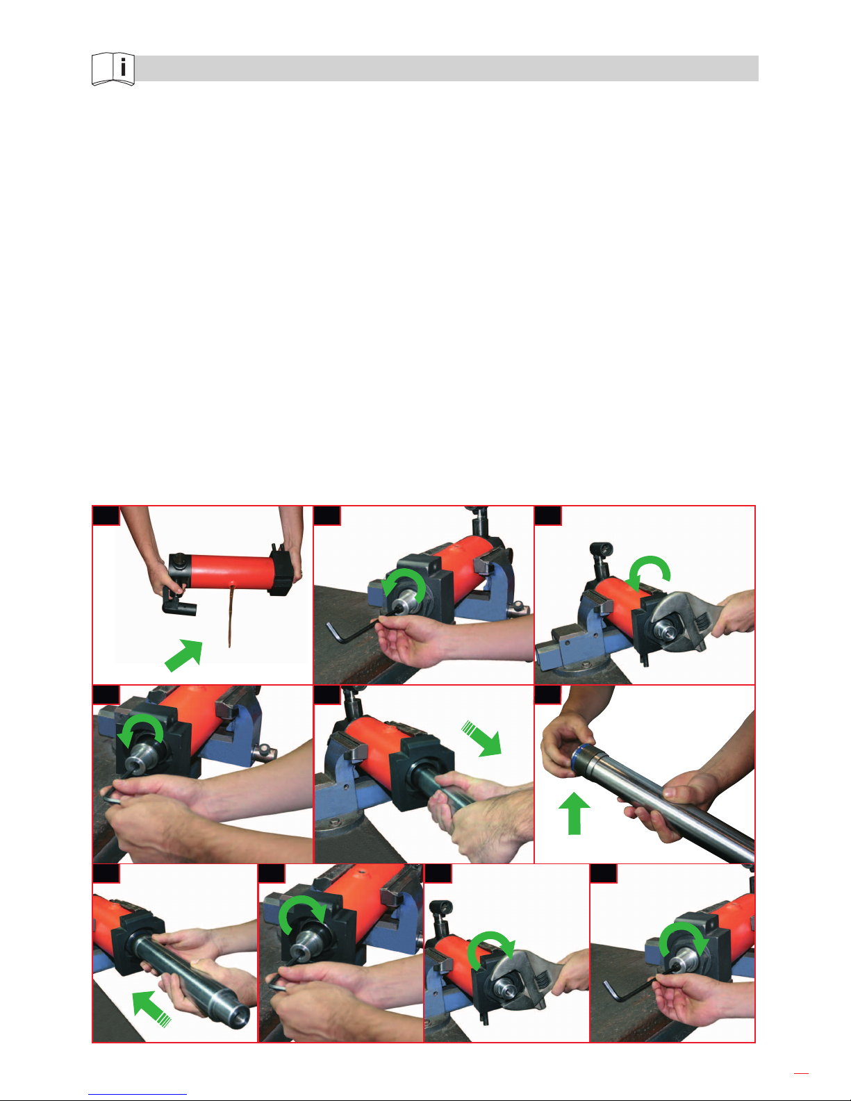
modo que a continuación se detalla:
1. Vaciar el déposito de aceite a través del tornillo superior.
2. Soltar la pieza Nº27 con ayuda de una llave hexagonal.
3. Soltar la pieza hexagonal Nº 33 con ayuda de una llave.
4. Soltar la pieza Nº28 con ayuda de una llave hexagonal.
5. Extraer el pistón pieza Nº30 con la mano.
6. Sustituir la junta del pistón Nº39 asegurándose de su correcta posición.
7. Introducir el pistón con suavidad para evitar dañar la junta.
8. Introducir la pieza Nº28 y apretar con ayuda de una llave hexagonal.
9. Introducir la pieza Nº33 y apretar con ayuda de una llave.
10. Introducir la pieza Nº27 y apretar con ayuda de una llave hexagonal.
4 5 6
1 2 3
7 8 9 10
6
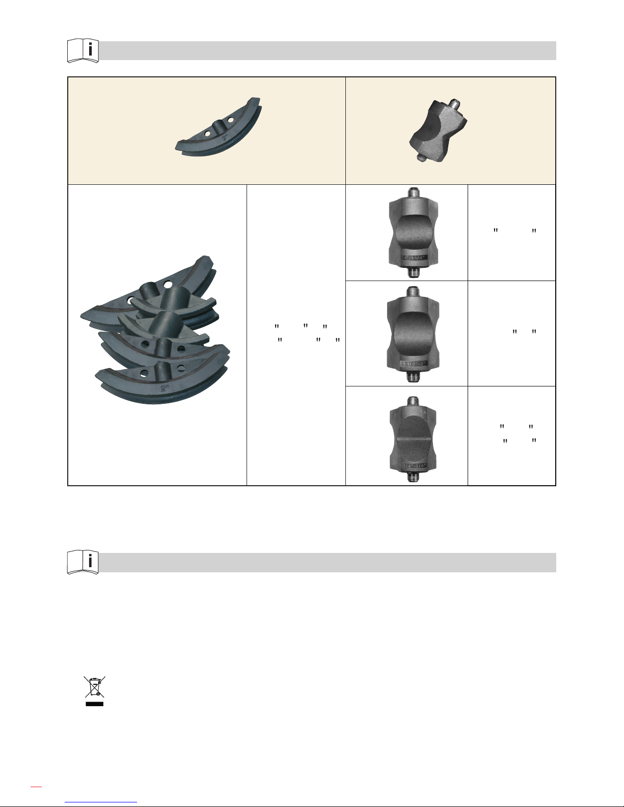
MEDIDAS DE GALLETAS Y DIÁBOLO
GALLETA
DIÁBOLO
(consta de 3 caras
diferentes)
1/2 - 3/4 - 1 -
1.1/4 - 1.1/2 - 2
1 - 1.1/4
1.1/2 - 2
1/4 - 3/8 -
1/2 - 3/4
NOTAS
¡IMPORTANTE!
El fabricante no se responsabiliza de los daños o mal funcionamiento de la máquina en caso de
que no se use correctamente o se haya utilizado para trabajos para los que no está diseñada.
Para pedir cualquier repuesto, mirar en el dibujo de despiece el número de la pieza deseada.
Según la directiva sobre residuos eléctricos de aparatos eléctricos y electrónicos
(RAEE), éstos deberán recogerse y tratarse por separado. Si en el futuro tiene que deshacerse de
este producto, no se deshaga de él junto con la basura doméstica. Póngase en contacto con su
distribuidor para proceder a su reciclaje de manera gratuita cuando sea posible.
7
GARANTÍA
El fabricante garantiza al comprador de ésta máquina la garantía total durante 12 meses de las
piezas con defectos de fabricación.
Esta garantía no cubre aquellas piezas que por su uso normal tienen un desgaste.
Nota: para obtener la validez de la garantía, es absolutamente imprescindible que complete y
remita al fabricante el documento de “CERTIFICADO DE GARANTIA”, dentro de los siete dias a
partir de la fecha de compra.
8
SAFETY INSTRUCTIONS
Attention! Be careful.
1. Do not wear loose clothing. They could be caught by moving parts of the machine.
2. Always wear gloves.
3. Always use the machine´s indicicated accesories because if you don´t, it could lead to risk of
personal injury.
4.
Don’t use or manipulate the machine standing in front of it (pipe welding area). User should
always stand at the back of the machine (hydraulic piston area).
5. Place always the forward supporting leg perfectly lined with the hydraulic piston to guarantee the
use safety.
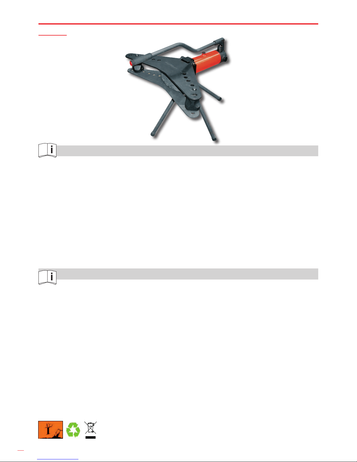
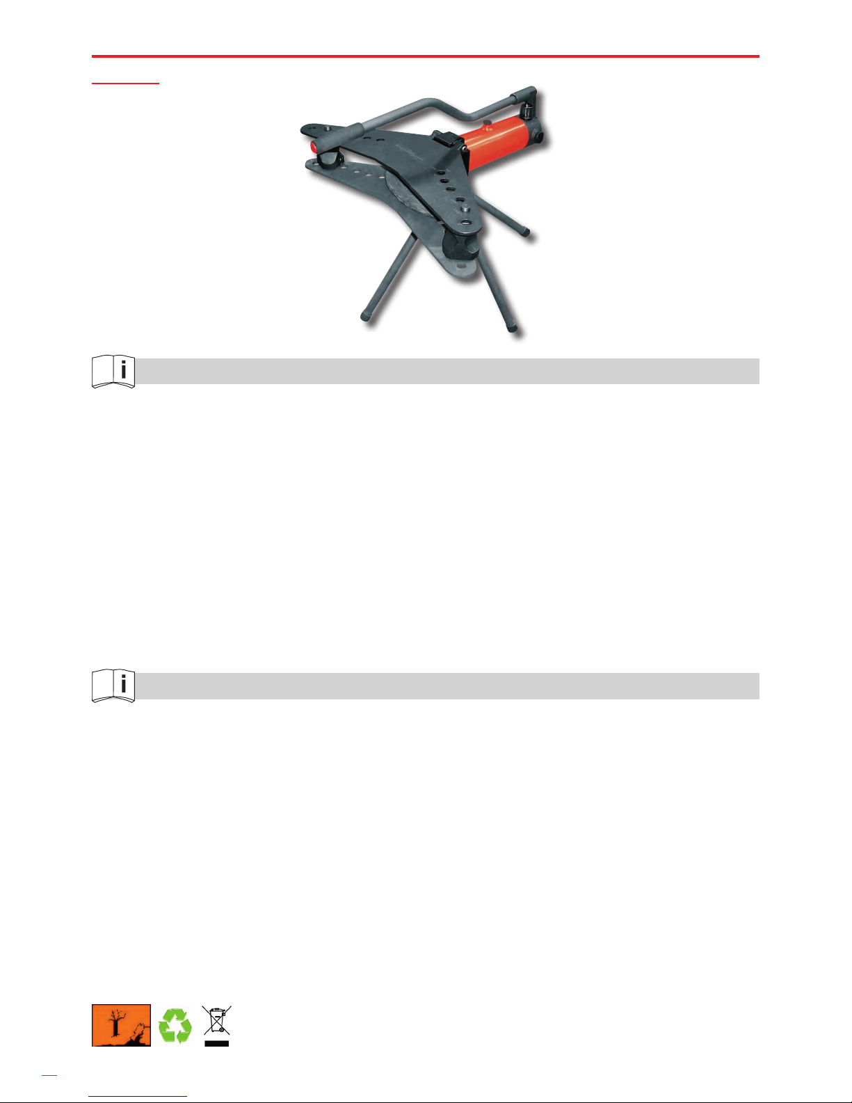
HIDRÁULIC PIPE BENDER – 2
Pipe bender machine properly equipped to bend steel pipe for conduction of water, gas, etc.
from ¼"÷2". The system of two speeds enables an automatic switch from “fast pre-loading” to
“soft bending” position without any need to change pistons. Fitted with double plate, wich gives
it the maximum consistency during the bending. Seated upon 3 legs of support to obtain a greater
stability.
Has a turn system for the cylinder and plates to be able to bend in difcult access areas.
- Cylinder rotation blocking system for increasing machine stability during pipe bending process.
- This pipe bender has been designed for bending pipes according to DIN-2440. Included a table
with the diameter and thickness specied by norm DIN-2440.
Working pressure : 10 Tm.
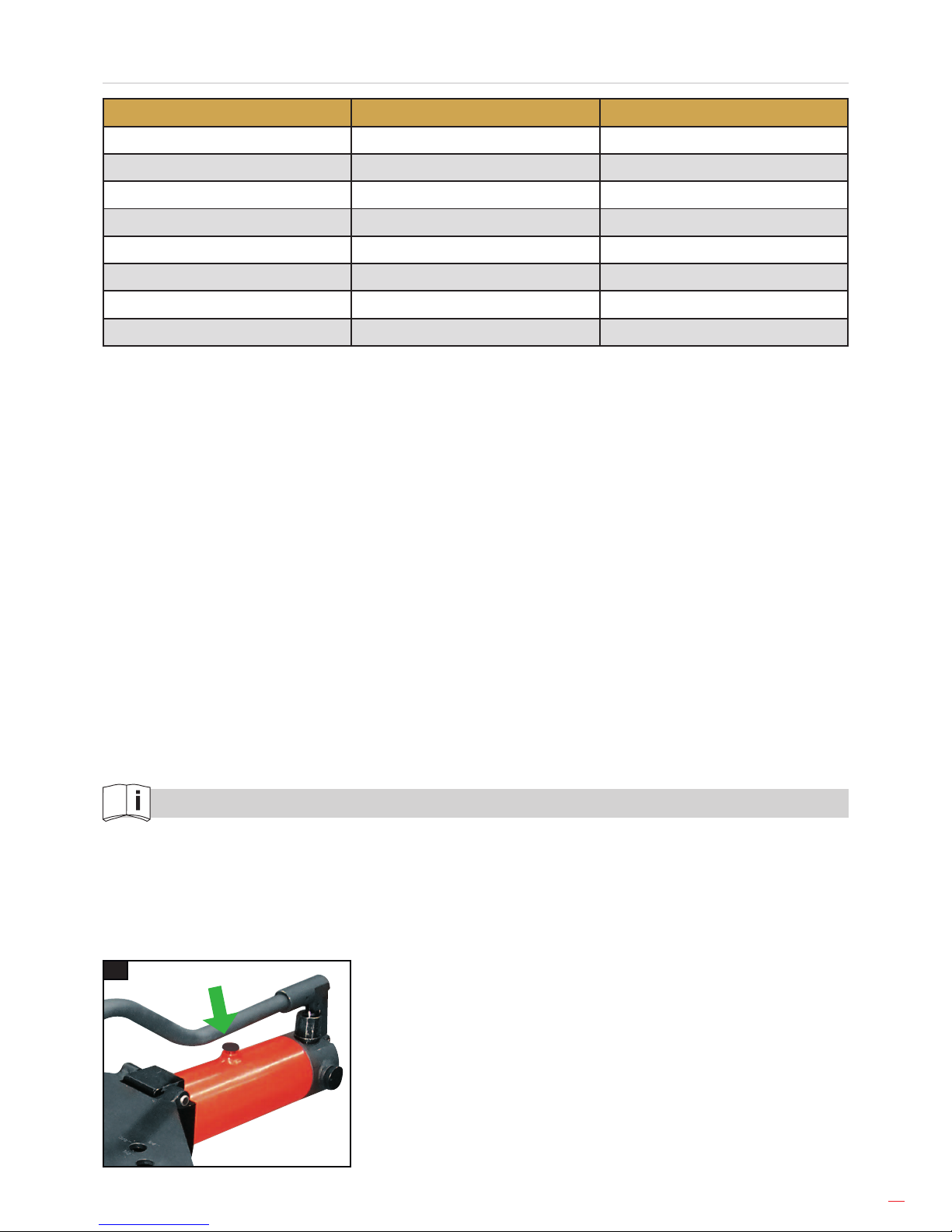
ATTENTION
Before beginning to work, loose slightly (a turn) the plug nº36
.
ENGLISH
9
TUBING DIAMETER & THICKNESS DIN-2440
SIZE EXTERIOR DIAMETER THICKNESS
1/4 13,5 2,35
3/8 17,2 2,35
1/2 21,3 2,65
3/4 26,9 2,65
1 33,7 3,25
1.1/4 42,4 3,25
1.1/2 48,3 3,65
2 60,3 3,65
MAINTENANCE
It is very important to use hidraulic oil and not any other type of uid.
Filter the oil before putting it into the deposit as any foreign substance can damage the O rings
or any of the valves.
The valve (nº50), in position of rest, must be opened and the piston withdraw, to avoid having
pressed the spring of the pistons return.
Before several days without being used, lubricate the end of the piston to avoid corrosions and
seizure while starting again its usage.
ADVICE
Take care while working, don’t place your body in front of the machine, that will avoid accidents.
IMPORTANT
When ordering spare parts please indicate its code number and the serial number of the machine.
GUIDE OF USAGE
A) FILLING THE DEPOSIT
Introduce through the plug (nº36) the oil. For that, it is strongly recommended to move back the
piston (with the runback roulette), stabilize the piston horizontally to level the oil fully, insert a rod
until a stop is found and measure 1,5cm of oil. This will be the ideal level of lling.
A
10
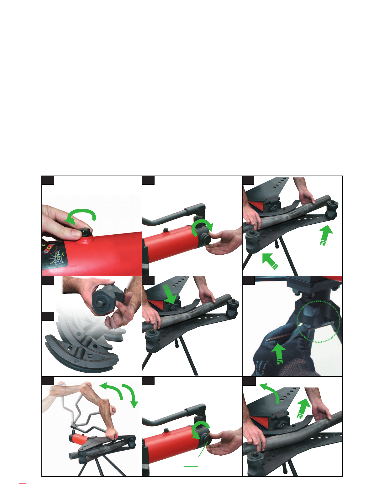
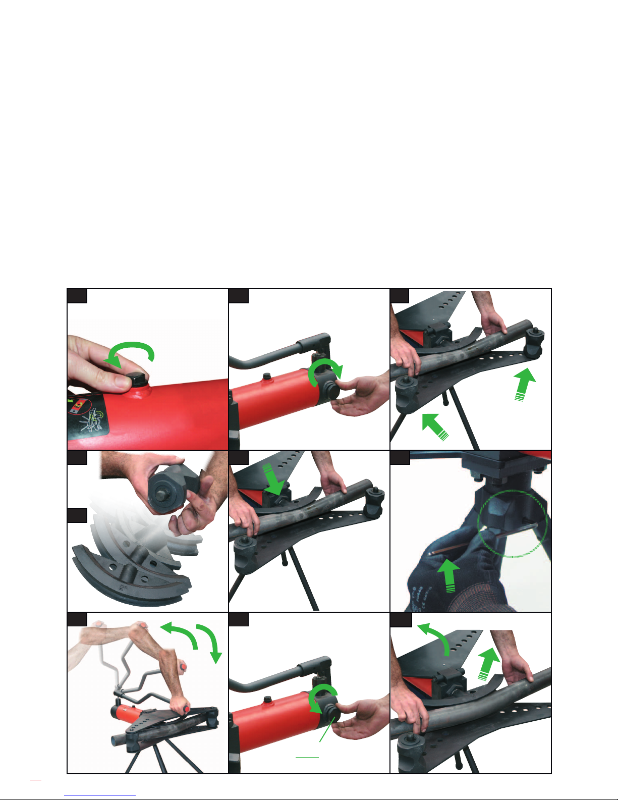
B) BENDING OF PIPES
B1. The upper screw for oil lling must be half-opened for use. It only must be completely closed
for transport.
B2. Close the valve (nº50).
B3. With the superior plate withdrawn, place both resting forms in their corresponding housings
of the interior plate according to the size of the pipe bent.
B4. Select the form corresponding to the resting form in the end of the piston.
B5. Place the corresponding form in the end of the piston.
B6. Insert the pipe to be bent, housing it between the form and the resting forms.
B7.
Cylinder rotation blocking system for increasing machine stability during pipe bending process.
Tight the screwed pin for avoiding rotation. Loosing screwed pin enables cylinder rotation
.
B8. Insert and actuate the bar, inside the housing of the big piston (left) and we will actuate it fast
untill the pipe contacts with the bending form. At this moment smooth-bending speed will
start, which enables bending with minimal effort.
B9. Once the bend is gotten, the (nº50) will be oppened and by making this action, the piston
will go back automatically.
B10.
Raise the superior plate and withdraw the form together with the bent pipe, removing it from
the same
.
B1 B2 B3
B4 B6
B5
B7
B8 B10B9
nº50
 Loading...