

EG corvus 540 60CC User Manual
EG AIRCRAFT
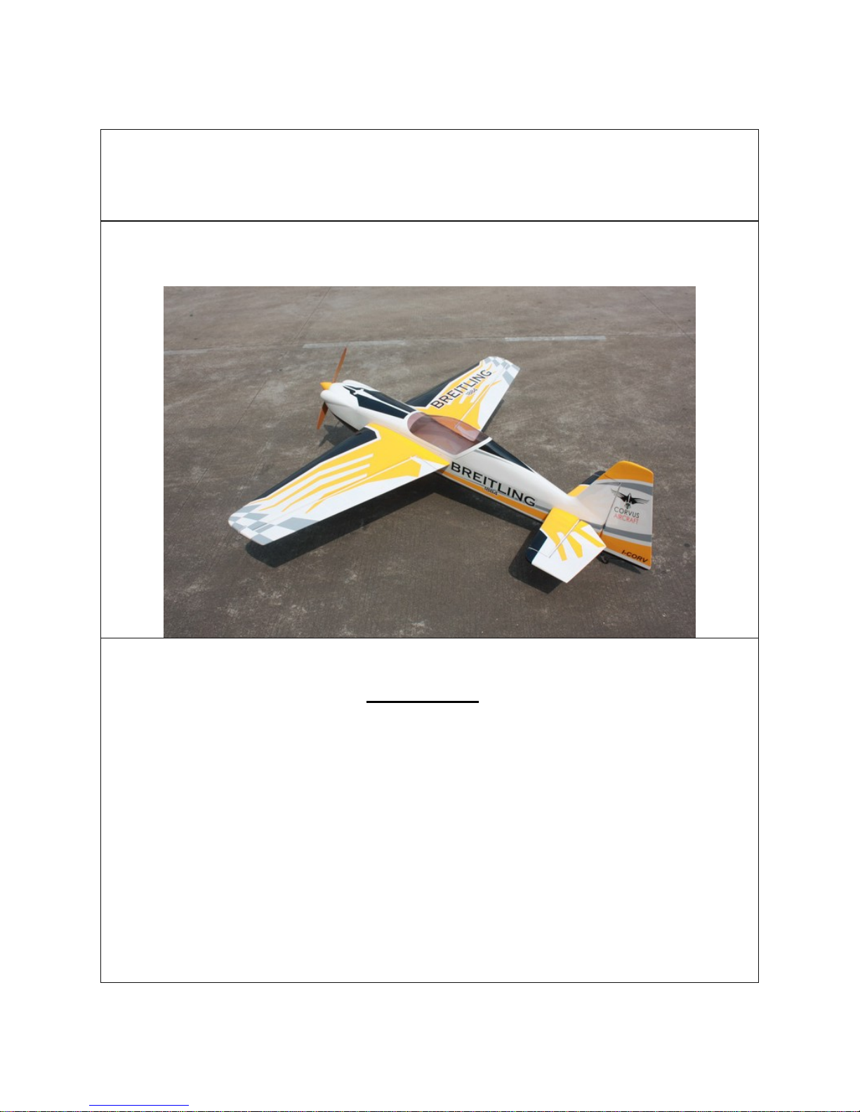
CORVUS 540 60CC
Giant Scale Aerobatic Aircraft
Specifications:
Scale: 30 %
Wing Span: 91”
Length: Including spinner 88 inches
Wing Area:1500 sq. in.
Flying Weight:16.5 to 18 lbs
Spinner:3.5”
Engine:50cc – 70cc Gas
Radio:4+ Channels
Servos :6 to 9 servos required 180 oz to 240 oz
All contents copyright 2013, EG Products
Version 2.0, Mar 2013

Dear EG Customer,
Thank you for purchasing the new EG 60CC Corvus 540. EG is known worldwide for the best aerobatic
aircraft designs available and include many innovative construction techniques. We’ve taken this
expertise and teamed up with EG Aircra ft to bring this new model to the radio control enth usiasts. The
Corvus is designed for the popular 50-70 cc engines and weighs about 16.5 lbs to 18 lbs. Perfect for
IMAC or Freestyle, this new EG giant offers everything you want in a giant scale aerobat i nc l u din g great
looks! Covered in genuine Ultracote, this ARF comes with premium hardware, carbon fiber landing gear,
carbon fiber wing and stab tubes, carbon fiber reinforced wing and fuselage spars, carbon fiber horns
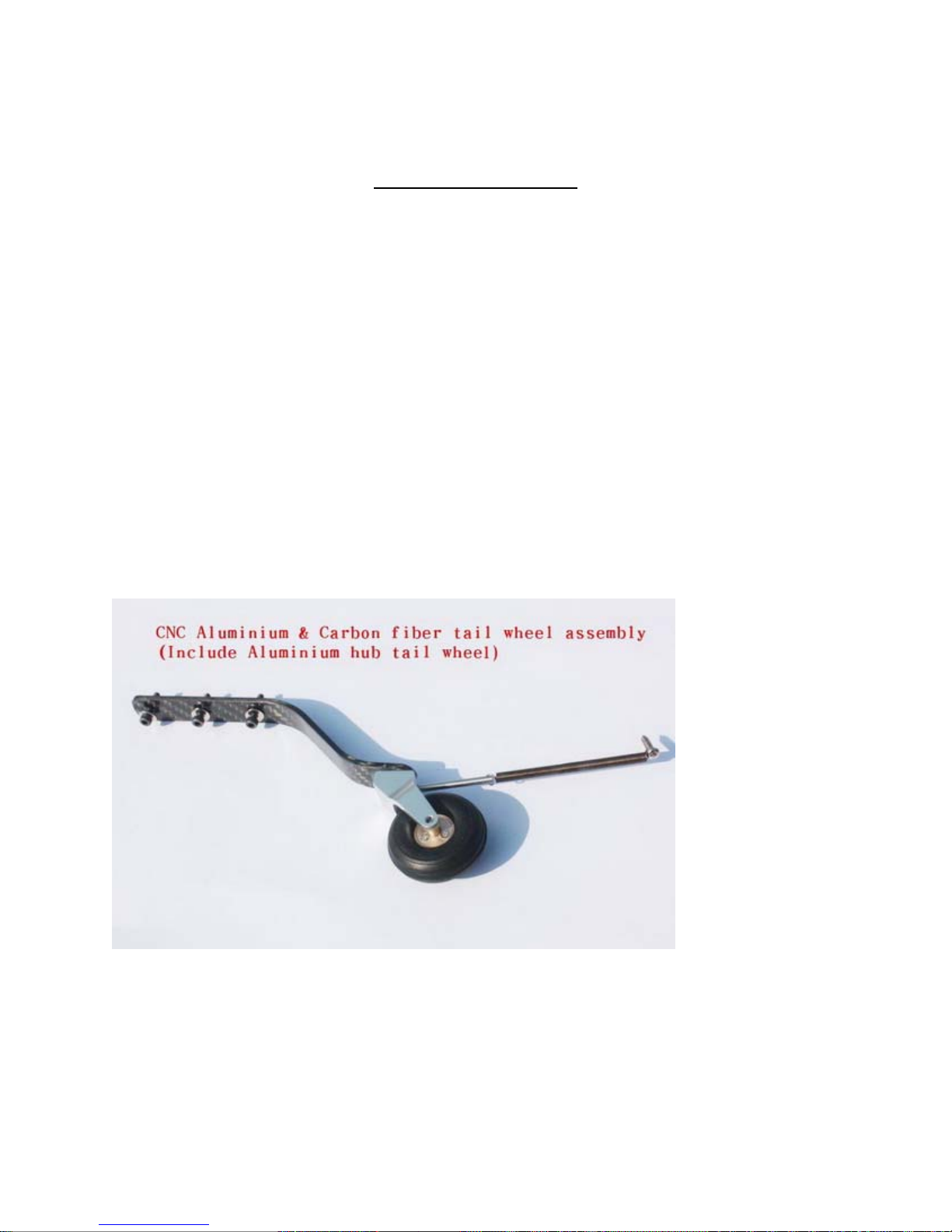
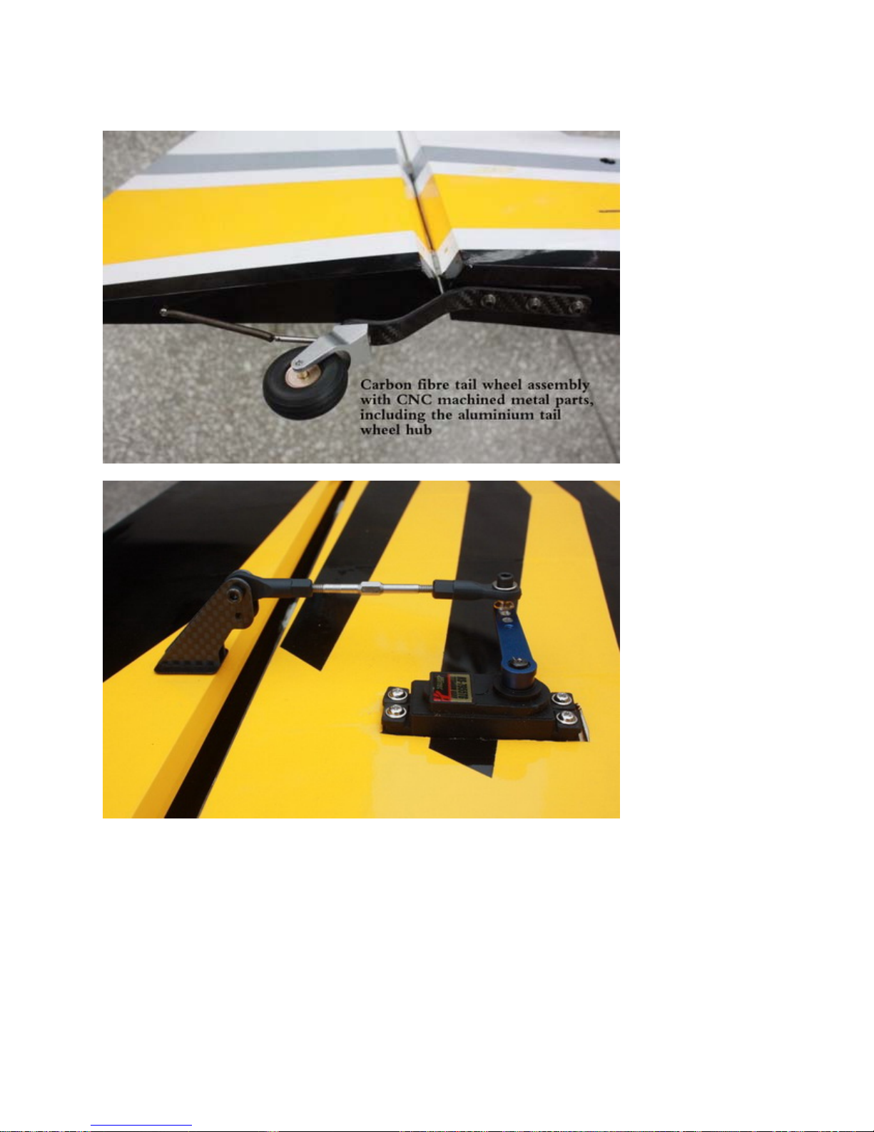
and pre-hinged elevators and ailerons. And also new Carbon fibre tail wheel assembly with CNC
machined metal parts, including the aluminium tail wheel hub.
We hope you will enjoy your new EG gia nt sca le aircraft as much as we have.
AN IMPORTANT MESSAGE ABOUT SAFETY AND RADIO CONTROL FLYING
MODELS
Flying radio control aircraft, like any hobby or sport, contains certain risks. The operator of these
models is responsible for these risks. If the airplane is misused or abused, you may cause serious bodily
injury and/or damage to property. With this in mind, you will want to be certain that you build your
model carefully and correctly. If you are not an experienced flier, have your work checked and ask for
help in learning to fly safely . This model aircraft is not a toy and must be operated and flown in a safe
manner at all times. Always perform a pre-flight check of the model including all control surfaces, proper
function of the radio gear, structure, radio range, and any other area relating to the safe operation of this
aircraft.
Models are not insurable but operators are. You can obtain coverage through membership in the
Academy of Model Aeronautics (AMA). For an AMA information package call 1-800-435-9262, ext.
292 or visit the AMA website at "www.modelaircraft.org
".
By the act of using the final assembled model, the purchaser/operator accepts
all resulting liability.

EG WARRANTY AND RETURN POLICY
EG guarantees this product to be free from defects in both material and workmansh i p at the date of
purchase. This does not cover any parts dam a ge d b y use, misuse or modification. In no case shall EG's
liability exceed the original cost of this kit. Because EG has no control over the final ass embly or
equipment/components used in the final assembly, no liability shall be assumed for any damage resulting
from the use of this model by the user. By the act of using the final asse mbled model, the user accepts
all resulting liability. If you should find any missing or damaged parts, or have any questions about this
product, please contact Red Aero RC within 30 days of the purchase in order to be covered by o ur
warranty. You may contact
Red Aero RC at sales@redaerorc.com or call Red Aero RC at
239-560-8175. If you wish to return this product you must first contact Red Aero RC and a 15%
restocking fee will be assessed. O nl y unused products may be returned. The cus tomer is responsible for
all return shipping charges both wa ys an d any damage as a result of misuse or shippi ng.
Included Features:
• Carbon fiber tail wheel assembly with
CNC machined metal parts, including
the aluminum tail wheel hub
• Carbon reinforced fuselage and
wings.
• Air foiled Carbon Fiber Landing Gear
• Carbon Fiber Wing and Stab Tubes
• Extra strength Carbon Fiber control
Horns
• 3.5"(89mm) Carbon Fiber Spinner
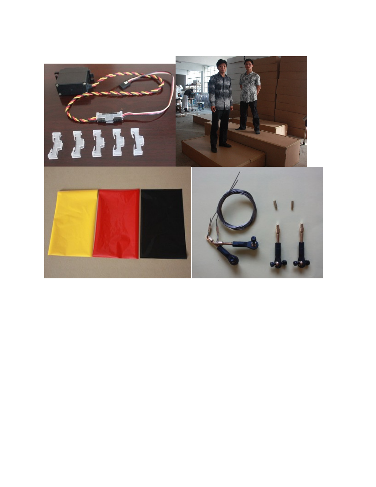
• Servo Lead Safety Clips
• High Density Rubber Wheels
• Adjustable pushrods for easy fine
tuning
• Pre-hinged Control Surfaces
• Pre-assembled and mounted Fuel
Tank
• Extra covering provided for small
repairs
• Installed Servo Wire Guide Tube
• Covered in Genuine Ultracote /
Oracover
• Complete and Detailed Instructions
on CD
• Fits new DA60 and 3W55 Engines
• Stronger design for fuselage and
wings
• Flat nylon hinges
• Honeycomb board carton packing
for safer transportation
• Larger C.F wing tube Diameter. Two
piece C.F tube for stab
• Larger aileron and rudder design. Up
to 60 degrees of throw on all control
surfaces for excellent 3D aerobatic
flying.
• Full length Tuned pipe design in
fuselage
• All high performance cap head
screws

Items Required to Complete This Model:
• 50-70 cc gas engine with stock or
aftermarket exhaust systems
• Appropriate propeller for your en gine
• All required engine and exhaust mounting
hardware
• Ignition battery and switch
• One quality throttle servo and appropriate
servo arm
• Four high quality metal gear servos of 180
in-oz or better for the ailerons and elevators
• One high quality rudder servo of least 240
in-oz or better
• Appropriate servo arms for the above
• Heavy duty servo wire extensions.
Recommended installation includes two 36”,
two 18”,, two 6” extensions. Your
installation though may vary.
• Two heavy duty switches with charging
jacks for the Rx
• Two high quality Rx batteries of high
capacity to power your choice of servos.
• Receiver of your choice
Shop Supplies/Tools
• Covering Iron and heat gun
• Assortment normal hobby tools such as
screwdrivers, hobby knife, drill and drill
bits, pliers, etc.
• Thick and Thin CA adhesives
• 30 minute Epoxy
• Isopropyl alcohol
• Ruler or tape measure
• Blue thread-lock or equivalent
Note: As with all kits, to correctly understand the construction of your airplane it is
important that you read all the instructions and study the parts before you begin
construction. Handle the parts of this kit with care so you do not damage any of the
structure or covering. Inspect all the parts for any shipping damage and report any
issues to EG as soon as you can. Make sure you have a flat and sturdy workbench
and follow all safety rules for the tools and adhesives you plan to use.
AIRCRAFT COVERING:
1. With all ARFs, varying temperatures and storage delays can cause covering material to loosen over
time and transportation. EG recommends lightly going over all the covering with a covering iron set
at medium temperatures. Be sure to use a soft cover over your iron so you d o not sc ratch the covering
surface. Be sure you go over all seams and edges of the covering to assure it is secure to the airframe
and other covering. Be careful not to apply too much heat or you may cause bubbles or damage to the
covering. A heat gun may also be used alon g with a soft cotton cloth to shrink and adhere the
covering. Again, be extremely careful when using a heat gun.
2. Be sure to seal any exposed wood with a thin coating of epoxy to prevent engine oil from soaking
in. This is especially important around the engine compartment and servo openings with exposed
areas.
3. Some modelers prefer to seal the hinge gaps using strips of appropriate covering or clear trim tape.
We have found this to be helpful with models intended for higher speed flight or models with
unusually large hinge gaps. EG aircraft utilize a very tight double beveled hinge line and do not
normally require this step. Sealing the hinge gaps is therefore left as an option for the modeler.
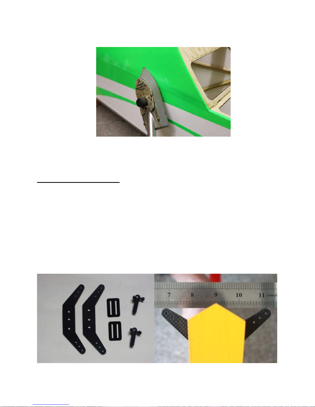
RUDDER INSTALLATION:
1. It is much easier to install the twin control horns before installing the rudde r. Loca te the Ca rbon Fiber
rudder control horns, ball links, and associated bolts and nylon-insert lock nuts. Use some fine
sandpaper to roughen up the center areas of the two control horns so that the glue adheres better.
Using a sharp hobby knife cut the covering away from the slots in the rudder and trial fit the two
control horns.
2. Mix up some 30 minute epoxy and coat the inside of the slots and the center of the control horns. Hint:
a scrap piece of 1/16” ply, tooth pick, or old hobby blade can be used to coat the inside of the rudder
slots. Slide the control horns in place and make sure they are centered perfectly by using a ruler to
measure between the pivot holes and the hinge line. Wipe any excess glue off with isopropyl alcohol
and paper towels. Install the ball links, bolts and nuts into the holes to help assure alignment of both
control horns while the glue cures. Set aside until cured. NOTE: There are pictures of different planes
in this manual, however, this plane’s rudder is assembled the same way.

3. The slots for the supplied flat hinges are pre cut. Locate the flat hinges and dry fit the hinges and
rudder into place and test the o peration. The hinges should seat fully into the slots so that the hinge
line gap is minimal while still allowing full rudder deflection.
4. Before gluing the hinges in you must first c lean the hinges of any mold release agent usin g isopropyl
alcohol, and scuff up the plastic with light sandpaper for maximum glue adhesion.
5. Mix up some 30 minute epoxy and using a toothpick or small wooden dowel coat the inside of each
hinge slot with epoxy. Also put a thin layer of epoxy on one end of the flat hinges. Install this end
into the slots of the rudder and make sure each hinge is properly aligned at exactly 90 degrees to the
hinge line.
6. Now coat the other end of the flat hinges with epoxy and install the rudder into the trailing edge of the
vertical stabilizer. Again, make sure the hinges remain in proper alignment. Using paper towels and
some isopropyl alcohol clean off any excess ep oxy from the hinges and surrounding areas.
7. Make sure the rudder is fully seated so that the hinge gap is minimal while still allowing full deflection
of the rudder. When satisfied, use some masking tape to hold the rudder in pl ace along the bottom and
counterbalance. After the epoxy has cured, remove the masking tape and check for proper operation.
If the hinges are dry some light oil carefully placed on each hinge will help greatly.
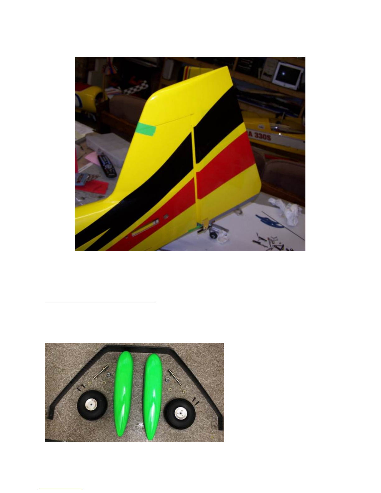
LANDING GEAR ASSEMBLY:
1. Locate the supplied main and tail wheel la nding gear parts and sort them out on your workbench.
NOTE: There are pictures of other planes in this manual, however, the Corvus is assembled the same
way.
 Loading...