

EFO MFT4 User Manual

MFT4 Multifunction Installation
Tester
- 1 -

User manual
Index
Safety information and explanation of symbols used .............................. 3
Features of the MFT4 ................................................................................... 5
Special Polarity Test Function. .................................................................. 6
Audible tones ............................................................................................... 7
Overview of the switches and LCD ......................................................... 8
Test lead inputs ............................................................................................ 9
Continuity Test Function ........................................................................... 10
Continuity Test Procedure ....................................................................... 10
Lead Nulling ............................................................................................ 10
Hands Free Continuity Testing ................................................................ 11
Insulation Test Function............................................................................ 12
Insulation Test Procedure ........................................................................ 12
Hands Free Insulation Testing ................................................................. 13
Loop Test functions ................................................................................... 14
High Current mode .................................................................................. 14
No Trip Mode ........................................................................................... 14
PFC/PSC................................................................................................. 15
Test lead configuration ............................................................................ 15
Lead configuration for No-Trip testing ..................................................... 16
Lead configuration for High current 2-wire testing ................................... 16
Loop Test Procedures ............................................................................. 17
No Trip Loop test (Zs) ............................................................................. 17
High current test (Ze) .............................................................................. 18
Hands Free Loop testing ......................................................................... 18
RCD Test Function ................................................................ ..................... 19
Ramp test ................................................................................................ 20
Sinusoidal polarity (the 0° or 180° test) ................................................... 20
RCD test procedure ................................................................................ 21
User selected test ................................................................................... 21
30mA Automatic test ............................................................................... 22
Ramp test ................................................................................................ 22
Specifications and tolerances .................................................................. 23
Continuity Test Range Accuracy .............................................................. 23
Insulation Test Range Accuracy .............................................................. 23
Insulation Output Voltage ........................................................................ 23
Loop Test Range Accuracy ...................................................................... 23
RCD Test Range Accuracy ...................................................................... 24
- 2 -

Safety information and explanation of symbols used
Because the MFT4 is a multi function tester used for testing both live and dead
circuits there are different safety issues that apply to the individual functions.
Before using your MFT4 please read these instructions paying particular
attention to the general safety warnings below and those at the start of each
section.
Before using the tester check the case and the test leads for damage.
If any damage is noticed the unit should be withdrawn from service and
returned to place of purchase for repair.
It is important for safety that only one set of leads can be fitted at a time. In the
unlikely event that the interlock cover is damaged the tester should be
withdrawn from service and returned to place of purchase for repair.
Caution read this manual for safety information
The Continuity and Insulation functions are rated at 500V Category III
The Loop and RCD functions are rated at 300V Category IV
When installing batteries observe correct polarity do not mix old and new
batteries - Dispose of used batteries in accordance with local regulations.
Never incinerate batteries.
Do not use this tester in a manner other than that described in this booklet.
To clean the tester wipe with a damp cloth with a mild soap solution taking care
not to allow water ingress into the input terminals. Do not use solvents and do
not immerse. Allow the tester to fully dry before use.
The MFT4 is fuse protected against damage by accidental connection to an
over-voltage supply. The fuse is located inside the battery compartment and
can be accessed by removing the two small battery cover retaining screws on
the back of the case. Always ensure that test leads are disconnected before
removing the battery cover.
- 3 -

The broken fuse indicator on the LCD will flag if the fuse has blown. It must be
MEASUREMENT
RANGE
OPERATING
RANGE
PER EN61557
OTHER
CONTINUITY
0.00 Ω - 19.99 kΩ.
0.1 Ω - 9.99kΩ.
IN>200mA
Uq < 7V
INSULATION
0.00 MΩ - 1999 MΩ
.
0.1 MΩ - 1990 MΩ.
IN = 1mA
LOOP HI-I
0.01 Ω - 500 Ω
1.04 Ω - 500Ω.
230V
50Hz
LOOP NO-TRIP
0.01 Ω - 500 Ω.
1.04 Ω - 500Ω.
230V
50Hz
RCD TRIP TIME
5 ms – 1999 ms
38 ms – 1999ms.
replaced with the correct type:
Fuse type: F 500mA fast blow ceramic 600V.
The enclosure is double insulated
Protected against over voltage to 550V
For safety reasons the tester is shipped without batteries fitted. To install
batteries remove the two small crosshead screws on the back of the
instrument that retain the battery cover and fit four Alkaline batteries type
AA / LR6 in accordance with the polarity shown.
The MFT4 complies fully with the requirements of EN61010.
The following table details the operating ranges for the individual functions
compliant with the performance requirements of EN61557.
- 4 -

Features of the MFT4
The MFT4 is packed with design features that maximise both convenience and
safety. These include:
Large display
To give the clearest results the MFT4 uses a large auto-backlit LCD which
makes reading the test results easy even when used in poorly lit areas.
Auto shut down
To preserve battery life when not in use the MFT4 incorporates an Auto-Off
function that powers the unit down after three minutes of inactivity. To resume
use after an Auto shut down a single press of any of the function buttons will
power up the unit.
Battery check
The first position either side of the off position of the rotary selector switch is a
battery check function.
Extended battery life
For simplicity the tester is powered by just four conventional AA (LR6) alkaline
batteries. The MFT4 has much lower power consumption than most testers
and therefore gives excellent battery life.
In addition to the battery status indicator that shows on the LCD, when the
battery power is becoming very low the Red warning LED will light to show that
imminent replacement is necessary. Always use Alkaline rather than zinc
carbon batteries.
Easy to locate
The test lead inputs are located on the top of the case allowing the tester to
stand vertically or be laid flat. Alternatively the unit can be carried by the
supplied neck strap.
Hands Free
Most of the test functions can utilise the Hands-Free mode in which the tester
is primed to automatically start the test as soon as the probes are connected to
a circuit, thereby leaving your hands free to hold the test probes.
Socket wiring check
To protect both the user and the instrument against harm caused by accidental
connection to an incorrectly wired supply the tester will automatically check the
polarity upon connection to a live supply. If the wiring has been incorrectly
connected testing will be inhibited an alarm will sound with flashing LED.
- 5 -
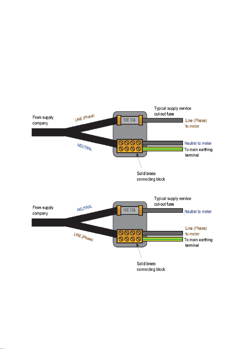
Special polarity test function.
It is a little known fact that a system can be reverse wired with Line (Phase) to
earth/neutral and earth/neutral to Line (Phase). The sockets will all work and
conventional loop testers will show and test that everything is correct despite
this very dangerous wiring condition.
Although extremely rare, this miss wire condition can exist so if your test
shows this fault do not proceed – if in any doubt advise your customer to
contact their supply company immediately.
Correct Polarity
Reversed Polarity
- 6 -

Audible tones
Danger
A rising siren type
alarm
In the event of a potentially dangerous situation
such as connecting to a live supply when
configured for insulation testing. Will be
accompanied by the Red Voltage/Polarity warning
LED flashing.
Warning
A continuous 2 tone
alarm
An unsuitable supply configuration such as a
mains supply with incorrect polarity or having the
leads connected wrongly will be accompanied by
the Red Voltage/Polarity warning LED flashing.
Wait-Test in progress
A steady beeping
sound
Emitted whilst a measurement is in progress. The
same tone is sounded when used in Hands free
mode to indicate that continual measurement is
being made
Test completed
A single beep
Sounded upon completion of a measurement to
indicate that the result is being displayed
Alert
A short 2 tone alarm
Sounded when a test returns a result that is likely
to be regarded as a failure e.g. An insulation test
that gives a result of less than 2 MΩ
A simple selection of audible tones is used to supplement the visual display.
These help the user by providing intuitive feedback during testing. In addition
to warning about dangerous or unstable supply conditions they provide a very
quick confirmation that the measurement process is taking place and, upon
completion of the test, a warning if the results are likely to be regarded as a
failure.
The meaning of the tone for each individual function is covered in detail in the
relevant section. Generally however there are five types of tone emitted.
- 7 -
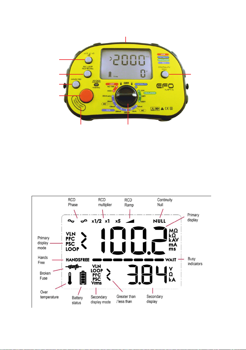
Test lead inputs
RCD
Muliplier
PFC-PSC /
RCD Recall
Polarity test
touch pad area
Hands free
Button
Test
Button
Function Selector
Continuity
Null Button
Overview of the switches and LCD
The Primary display of the large LCD shows the result of the test being
conducted. At the same time a secondary display area shows supporting
information e.g. for an insulation test the main display shows the resistance of
the insulation whilst the secondary display confirms the test voltage applied.
- 8 -
 Loading...