

Page 1

Flow Computer Division
eFlow EF-Series Flow Computer
Instruction Manual
Form A6103
February 2001
Loose-leaf version: Part Number D301149X012
Bound version: Contact FAS
Page 2

EF-Series Instruction Manual
Revision Tracking Sheet
February 2001
This manual may be revised periodically to incorporate new or updated information. The date revision
level of each page is indicated at the bottom of the page opposite the page number. A major change in
the content of the manual also changes the date of the manual which appears on the front cover. Listed
below is the date revision level of each page.
Page Revision
All pages 2/01
Fisher Controls International, Inc. 2001. All rights reserved.
Printed in the U.S.A.
While this information is presented in good faith and believed to be accurate, Fisher Controls does not guarantee satisfactory results from
reliance upon such information.
performance, merchantability, fitness or any other matter with respect to the products
process in conflict with any patent. Fisher Controls reserves the right, without notice, to alter or improve the designs or specifications of the
products described herein.
ii Rev 2/01
Nothing contained herein is to be construed as a warranty or guarantee, express or implied, regarding the
, nor as a recommendation to use any product or
Page 3

EF-Series Instruction Manual
Table of Contents
SECTION 1 — GENERAL INFORMATION ............................................................ 1-1
1.1 Manual Overview ........................................................................................................................ 1-1
1.2 Section Contents .......................................................................................................................... 1-2
1.3 Additional Information ................................................................................................................ 1-2
1.4 Product Overview ........................................................................................................................ 1-3
1.5 Installation Requirements ............................................................................................................ 1-7
1.6 Mounting.................................................................................................................................... 1-12
1.7 Power Consumption Calculation ............................................................................................... 1-15
1.8 Startup and Operation ................................................................................................................ 1-20
SECTION 2 — USING THE EF-SERIES UNIT ........................................................ 2-1
2.1 Scope............................................................................................................................................ 2-1
2.2 Section Contents .......................................................................................................................... 2-1
2.3 Product Functions ........................................................................................................................ 2-3
2.4 Product Electronics ...................................................................................................................... 2-8
2.5 Connecting the EF-Series unit to Wiring................................................................................... 2-15
2.6Configuration.............................................................................................................................2-26
2.7Calibration.................................................................................................................................2-27
2.8 Troubleshooting and Repair....................................................................................................... 2-28
2.9 Specifications............................................................................................................................. 2-35
SECTION 3 — COMMUNICATION CARDS ........................................................... 3-1
3.1 Scope............................................................................................................................................ 3-1
3.2 Section Contents .......................................................................................................................... 3-1
3.3 Product Descriptions.................................................................................................................... 3-2
3.4 Initial Installation and Setup........................................................................................................ 3-8
3.5 Connecting Communications Cards to Wiring.......................................................................... 3-10
3.6 Troubleshooting and Repair....................................................................................................... 3-13
3.7 Communication Cards Specifications........................................................................................ 3-15
Rev 2/01 iii
Page 4

EF-Series Instruction Manual
Table of Contents (Continued)
SECTION 4 — THE FLOW SENSOR ........................................................................ 4-1
4.1 Scope ............................................................................................................................................4-1
4.2 Description ...................................................................................................................................4-1
4.3 Process Connections..................................................................................................................... 4-2
4.4 Sensor Wiring............................................................................................................................... 4-2
4.5 Configuration ...............................................................................................................................4-3
4.6 Calibration....................................................................................................................................4-4
4.7 Specifications ...............................................................................................................................4-8
GLOSSARY OF TERMS ............................................................................................. G-1
INDEX ..............................................................................................................................I-1
iv Rev 2/01
Page 5

EF-Series Instruction Manual
SECTION 1 — GENERAL INFORMATION
1.1 MANUAL OVERVIEW
This manual describes the eFlow™ EF-Series Flow Computer, part of the family of flow computers
manufactured by Fisher Controls. Included in this manual are the following sections:
♦
Table of Contents Table of Contents
♦
Section 1 General Information
♦
Section 2 Using the EF-Series Unit
♦
Section 3 Communications Cards
♦
Section 4 Flow Sensor
♦
Glossary Glossary of Terms
♦
Index Topical Index
Table of Contents lists each section and information contained in that section of the document.
Section 1, which you are now reading, describes this manual and mentions related manuals. This
section also provides a summary of the EF-Series hardware, installation requirements, mounting the
unit, and power requirements.
Section 2 provides information and specifications concerning the use of the EF-Series Flow Computer.
Topics covered include the Main Electronics Board, wiring, configuration, and troubleshooting.
Section 3 provides information and specifications for the communications cards.
Section 4 describes the flow sensor included with the unit for sensing static pressure and differential
pressure.
Glossary of Terms defines terms used in this document and related documents.
Topical Index alphabetically lists the items contained in this manual along with their page numbers.
Rev 2/01 1-1
Page 6

General Information
1.2 SECTION CONTENTS
This section contains the following information:
Information Section Page Number
Manual Overview 1.1 1-1
Additional Information 1.3 1-2
Product Overview 1.4 1-3
Options 1.4.1 1-6
Installation Requirements 1.5 1-7
Environmental Requirements 1.5.1 1-7
Site Requirements 1.5.2 1-8
Compliance with Hazardous Area Standards 1.5.3 1-9
Power Installation Requirements 1.5.4 1-9
Grounding Installation Requirements 1.5.5 1-10
I/O Wiring Requirements 1.5.6 1-11
Mounting 1.6 1-12
Mounting the EF-Series Unit 1.6.1 1-12
Mounting a Radio 1.6.2 1-14
Accessing the Battery Compartment 1.6.3 1-14
Power Consumption Calculation 1.7 1-15
Determining I/O Channel Power Consumption 1.7.1 1-15
Determining Auxiliary Power Consumption 1.7.2 1-16
Totaling Power Requirements 1.7.3 1-16
Solar-Powered Installations 1.7.4 1-17
Batteries 1.7.5 1-19
Startup and Operation 1.8 1-20
Startup 1.8.1 1-20
Operation 1.8.2 1-20
1.3 ADDITIONAL INFORMATION
The following manuals may be used to acquire additional information, not necessarily found in this
manual:
! ROCLINK for Windows Configuration Software User Manual – Part Number
D301138X012
! ROCLINK Configuration Software User Manual – Part Number D301101X012
! ROC/FloBoss Accessories Instruction Manual – Part Number D301061X012
1-2 Rev 2/01
Page 7

EF-Series Instruction Manual
1.4 PRODUCT OVERVIEW
The eFlow EF-Series units are 32-bit microprocessor-based Electronic Flow Measurement (EFM)
computers that provide functions required for measuring the flow at a single meter run. The EF-Series
unit measures differential pressure, static pressure, and temperature; in addition, it provides the
functions required for gas orifice metering.
The EF-Series Unit computes gas flow for both volume and energy. The unit provides on-site
functionality and supports remote monitoring, measurement, data archival, and communications. The
design allows you to configure specific applications including those requiring gas flow calculations,
data archival, and remote communications.
The EF-Series Unit provides the following standard components and features:
♦
Weather-tight enclosure.
♦
Main Electronics Board.
♦
Built-in Liquid Crystal Display (LCD) with two-line alphanumeric viewing.
♦
A 32-bit microprocessor, 512K of flash ROM, and 512K of static memory storage.
♦
Built-in Sensor for orifice metering.
♦
Built-in Resistance Temperature Detector (RTD) input.
♦
Built-in Discrete Output (DO) for sampler or odorizer control.
♦
Up to 28 amp-hour battery capacity.
♦
Operator interface (LOI) port.
♦
Host communications port for optional communications card.
Physically, the unit consists of a printed-circuit Main Electronics Board and a display housed in a
compact, weather-tight case. The EF-Series unit is packaged in a NEMA 4 windowed enclosure that
can mount on a wall or a pipestand. A cover is provided for the display to protect it from adverse
weather conditions. Refer to Figure 1-1.
The steel enclosure protects the electronics from physical damage and harsh environments. The
enclosure consists of two pieces: the body and the door. A foam-rubber gasket seals the unit when the
hinged door is closed. The hinge, located on the left side, is stainless steel and fastened to the body
with machine screws, allowing removal of the door. The door is secured by a lockable hasp. Refer to
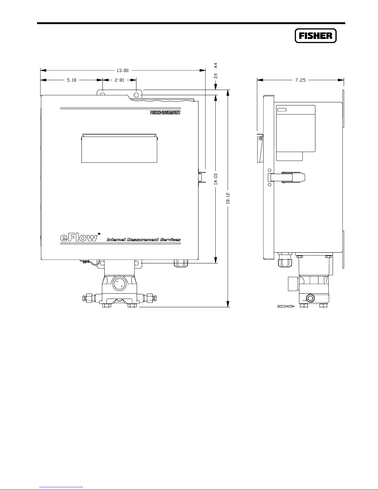
Figure 1-2 on page 1-13 for dimensional details.
The Main Electronics Board mounts on quick-fastener stand-offs located on top of the swing-out
panel. The dimensions of the board are approximately 5 by 7.5 inches. The majority of the
components are surface-mounted, with the top side of the board used for components. The Main
Electronics Board provides built-in I/O capabilities, an LCD display, and provisions for an optional
communications card. For more information on the Main Electronics Board, refer to Section 2.
Rev 2/01 1-3
Page 8
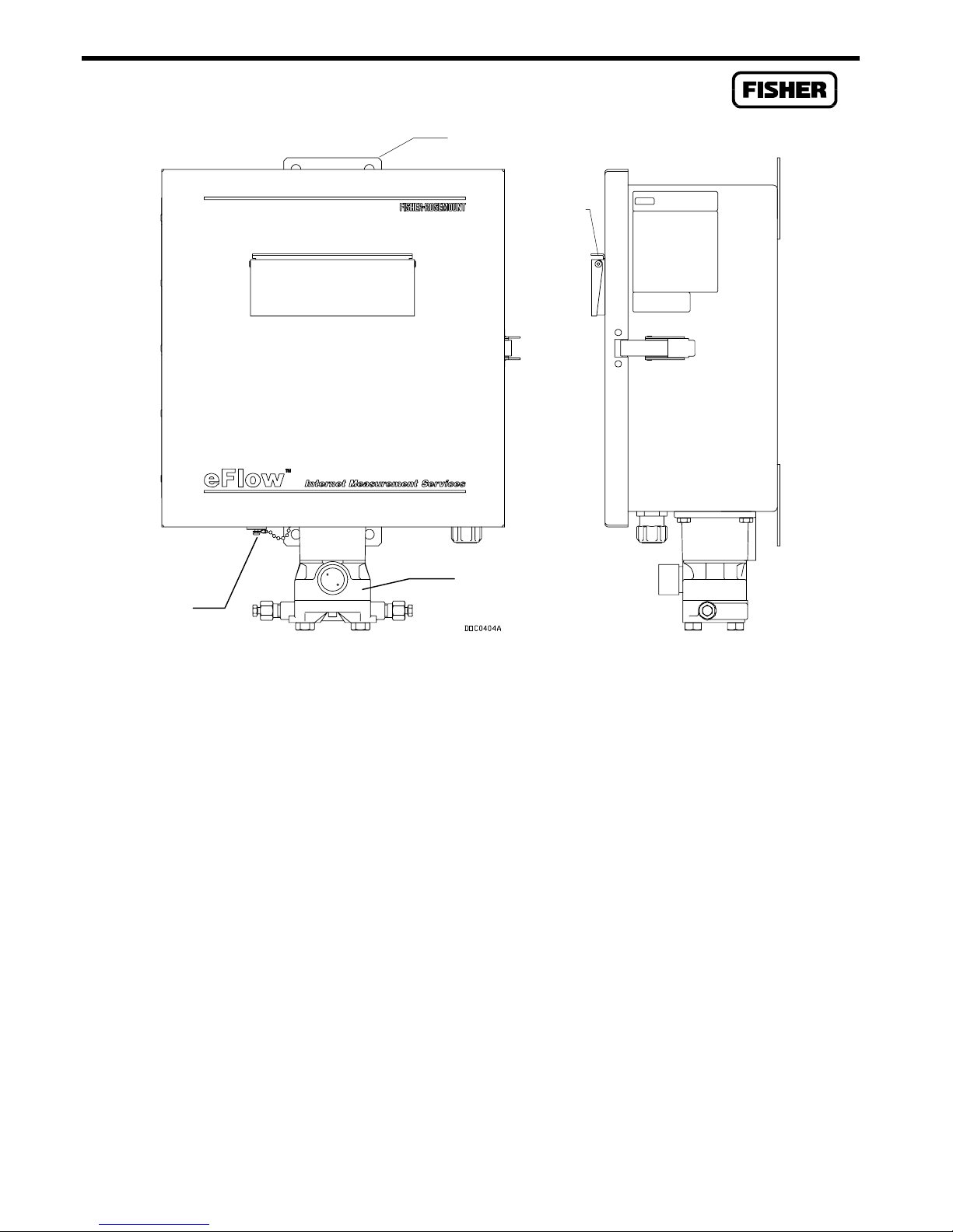
General Information
Mounting Flange
Display
Cover
Operator
Interface
Connector
Sensor
Figure 1-1. eFlow EF-Series Flow Computer
The built-in Liquid Crystal Display (LCD) provides the ability to look at data and configuration
parameters while on site without using the local operator interface (LOI) and a PC. The LCD display
is factory-mounted directly to the Main Electronics Board and visible through the window on the front
panel. Through this display, you can view pre-determined information stored in the unit. Up to 16
items can be defined for display. The display automatically cycles through the configured list of items
displaying a new value approximately every three seconds.
A Motorola 32-bit CMOS microprocessor runs at 14.7 MHz and has low-power operating modes,
including inactivity and low battery condition. The EF-Series Unit comes standard with 512K of builtin, super capacitor-backed static random access memory (SRAM) for storing data and history. The
unit also has 512K of programmable read-only memory (flash ROM) for storing operating system
firmware, applications firmware, and configuration parameters.
The built-in inputs and outputs (I/O) on the EF-Series Unit consist of a port for the Sensor, a 4-wire
Resistance Temperature Detector (RTD) input interface, and a discrete output (DO). Three diagnostic
inputs are dedicated to monitoring battery voltage, charger voltage, and enclosure/battery temperature.
Refer to Section 2 for more information.
1-4 Rev 2/01
Page 9

EF-Series Instruction Manual
The orifice-metering Sensor measures differential pressure and absolute or gauge (static) pressure by
converting the applied pressure to electrical signals and making the readings available to the Main
Electronics Board. The Sensor housing fastens to a flanged adapter, which in turn mounts with four
bolts to the bottom of the enclosure. The Sensor cable plugs directly into the Main Electronics Board.
For more information on the Sensor, refer to Section 4.
An RTD temperature probe typically mounts in a thermowell on the metering pipe. RTD wires
should be protected either by a metal sheath or conduit connected to a liquid-tight conduit fitting on the
bottom of the EF-Series enclosure. The RTD wires connect directly to the four-terminal RTD
connector on the Main Electronics Board inside the enclosure.
The built-in discrete output (DO) is capable of directly driving a sampler or odorizer. The DO may
be used as a Timed Duration Output (TDO).
The operator interface (LOI) port, located on the bottom left-hand side of the enclosure (refer to
Figure 1-1), provides for a direct, local link between the EF-Series Unit and a personal computer
through an Operator Interface Cable. With the personal computer running the ROCLINK
Configuration Software, you can configure the functionality of the unit and monitor its operation.
User-level security can be enabled or disabled for the LOI port.
The host communications port (located at COM1) is available for use with an optional
communications card to permit serial communication protocols, as well as dial-up modem
communications. User-level security can be enabled or disabled for the host communications port
The I/O parameters, Sensor inputs, flow calculations, power control, and security are configured and
accessed using the ROCLINK Configuration Software. Refer to the ROCLINK for Windows User
Manual (or the DOS-based ROCLINK user manual) for details concerning software capabilities.
The firmware, contained in flash ROM on the electronics board, determines much of the functionality
of the EF-Series Unit, such as:
♦
Memory logging of 240 alarms and 240 events.
♦
Archival of data for up to 15 history points for up to 35 days.
♦
Power cycling control for a radio or cell phone through the EIA-232 communications card.
♦
Flow calculations (AGA and API standards) for a single meter run.
♦
Communications support alarm call-in to host.
♦
User-level security.
Refer to Section 2.3 for more information about the functionality provided by the firmware.
Rev 2/01 1-5
Page 10

General Information
1.4.1 Options and Accessories
The EF-Series Unit supports the following options and accessories:
♦
Communications Cards for host communications.
♦
Bracket for internally-mounted radio.
♦
Local Operator Interface (LOI) cable.
♦
Batteries.
♦
Solar Panels.
A variety of plug-in communication cards are available that allow you to customize the EF-Series
Unit installation for most communications requirements. The communication cards provide an
interface for the host communications port. These cards permit serial communication protocols, as
well as dial-up modem communications. One card of the following types can be accommodated:
♦
EIA-232 (RS-232) for asynchronous serial communications.
♦
EIA-485 (RS-485) for asynchronous serial multi-drop communications.
♦
Dial-up modem for communications over a telephone network.
Stand-offs on the Main Electronics Board allow the communications cards to be added easily. Refer to
Section 3 for more information.
A radio with an integral modem can also be mounted inside the enclosure using the optional radio
bracket (see Section 1.6). The radio bracket allows a radio up to 2.25 inches high to be mounted
securely in the battery compartment inside the enclosure. Power for the radio can be controlled
through the EIA-232 communications card. Clearance is provided for the radio antenna cable to exit
the bottom of the enclosure.
The local operator interface (LOI) port provides for a direct, local link using an Operator Interface
Cable between the EF-Series Unit and a personal computer. With the personal computer running the
ROCLINK Configuration Software, you can configure the functionality of the unit and monitor its
operation. The Operator Interface Cable is available as an accessory.
The EF-Series Unit enclosure can hold up to four sealed lead-acid batteries. The 12-volt batteries
provide approximately 7 amp-hours each, resulting in up to 28 amp-hours of backup capacity. The
batteries are mounted behind the electronics swing-out panel and are retained by the panel when it is
secured. The batteries are connected to a wiring harness that allows the batteries to be changed
without removing power from the unit. Refer to Section 1.7.5 for more information.
A solar panel can be installed to recharge the backup batteries; it connects to the POWER charge
inputs on the Main Electronics Board. Circuitry on the Main Electronics Board monitors and regulates
the charge based on battery voltage, charging voltage, and temperature. The typical panels used are
12-volt panels with output ratings of 5 or 10 watts. The panels are typically bracket-mounted on a pole
or pipe, and the wiring is brought into the bottom of the enclosure through a liquid-tight fitting.
1-6 Rev 2/01
Page 11

EF-Series Instruction Manual
1.5 INSTALLATION REQUIREMENTS
This section provides generalized guidelines for successful installation and operation of the EF-Series
Unit. Planning helps to ensure a smooth installation. Be sure to consider location, ground conditions,
climate, and site accessibility while planning an installation.
The versatility of the EF-Series Unit allows it to be used in many types of installations. For additional
information concerning a specific installation, contact your Fisher Representative. For detailed wiring
information, refer to Section 2.
The Installation Requirements section includes:
♦
Environmental Requirements
♦
Site Requirements
♦
Compliance with Hazardous Area Standards
♦
Power Installation Requirements
♦
Grounding Installation Requirements
♦
I/O Wiring Requirements
NOTE
The EF-Series Unit has been tested and found to comply with the limits for a Class
A digital device, pursuant to part 15 of the FCC Rules. These limits are designed to
provide reasonable protection against harmful interference when the equipment is
operated in a commercial environment. This equipment generates, uses, and can
radiate radio frequency energy. If not installed and used in accordance with this
instruction manual, the EF-Series Unit may cause harmful interference to radio
communications. Operation of the equipment in a residential area is likely to cause
harmful interference, in which case you will be required to correct the interference
at your own expense.
1.5.1 Environmental Requirements
The EF-Series Unit case is classified as a NEMA 4 equivalent enclosure. This provides the level of
protection required to keep the units operating under a variety of weather conditions.
The unit is designed to operate over a wide range of temperatures. However, in extreme climates it
may be necessary to moderate the temperature in which the unit must operate.
The unit is designed to operate over a -40 to 75°
temperature range is -25 to 70° C (-13 to 158° F). When mounting the unit, be aware of external
devices that could have an effect on the operating temperature. Operation beyond the recommended
temperature range could cause errors and erratic performance. Prolonged operation under extreme
conditions could also result in failure of the unit.
Rev 2/01 1-7
C (-40 to 167° F) temperature range. The LCD
Page 12

General Information
Check the installation for mechanical vibration. The EF-Series Unit should not be exposed to levels of
vibration that exceed 2 G for 15 to 150 hertz and 1 G for 150 to 2000 hertz.
1.5.2 Site Requirements
Careful consideration in locating the EF-Series Unit on the site can help prevent future operational
problems. The following items should be considered when choosing a location:
♦
Local, state, and federal codes often place restrictions on monitoring locations and dictate
site requirements. Examples of these restrictions are fall distance from a meter run,
distance from pipe flanges, and hazardous area classifications.
♦
Locate the unit to minimize the length of signal and power wiring.
♦
Orient solar panels to face due South (not magnetic South) in the Northern Hemisphere and
due North (not magnetic North) in the Southern Hemisphere. Make sure nothing blocks the
sunlight from 9:00 AM to 4:00 PM.
♦
Antennas are equipped for radio communications and must be located with an unobstructed
signal path. If possible, locate antennas at the highest point on the site and avoid aiming
antennas into storage tanks, buildings, or other tall structures. Allow sufficient overhead
clearance to raise the antenna.
♦
To minimize interference with radio communications, locate the unit away from electrical
noise sources such as engines, large electric motors, and utility line transformers.
♦
Locate the unit away from heavy traffic areas to reduce the risk of being damaged by
vehicles. However, provide adequate vehicle access to aid in monitoring and maintenance.
1-8 Rev 2/01
Page 13

EF-Series Instruction Manual
1.5.3 Compliance with Hazardous Area Standards
The EF-Series Unit has hazardous location approval for Class I, Division 2, Groups A to D exposures.
The Class, Division, and Group terms are defined as follows:
Class defines the general nature of the hazardous material in the surrounding atmosphere.
Class I is for locations where flammable gases or vapors may be present in the air in
quantities sufficient to produce explosive or ignitable mixtures.
Division defines the probability of hazardous material being present in an ignitable
concentration in the surrounding atmosphere. Division 2 locations are presumed to be
hazardous only in an abnormal situation.
Group defines the hazardous material in the surrounding atmosphere. Groups A to D are
defined as follows:
♦
Group A – Atmosphere containing acetylene.
♦
Group B – Atmosphere containing hydrogen, gases or vapors of equivalent nature.
♦
Group C – Atmosphere containing ethylene, gases or vapors of equivalent hazards.
♦
Group D – Atmosphere containing propane, gases or vapors of equivalent hazards.
For the EF-Series Unit to be approved for hazardous locations, it must be installed according to the
National Electrical Code (NEC) Article 501.
CAUTION
When installing units in a hazardous area, make sure all installation
components selected are labeled for use in such areas. Installation and
maintenance must be performed only when the area is known to be nonhazardous.
1.5.4 Power Installation Requirements
The typical source of primary power for EF-Series Unit installations is solar power.
Refer to Section 1.7, Power Consumption Calculation, on Page 1-15 concerning solar power, auxiliary
device power, and batteries.
Rev 2/01 1-9
Page 14

General Information
1.5.5 Grounding Installation Requirements
Ground wiring requirements for are governed by the National Electrical Code (NEC).
Proper grounding of the EF-Series Unit helps to reduce the effects of electrical noise on the unit’s
operation and protects against lightning. Lightning protection is designed into the unit, especially for
the built-in field wiring inputs and outputs. You may want to consider installing a telephone surge
protector for the dial-up modem communications card.
All earth grounds must have an earth to ground rod or grid impedance of 25 ohms or less as measured
with a ground system tester. The grounding conductor should have a resistance of 1 ohm or less between
the EF-Series Unit case ground lug and the earth ground rod or grid.
The grounding installation method for the unit depends on whether the pipeline has cathodic protection.
On pipelines with cathodic protection, the EF-Series Unit must be electrically isolated from the pipeline.
Electrical isolation can be accomplished by using insulating flanges upstream and downstream on the
meter run. In this case, the EF-Series Unit could be flange mounted or saddle-clamp mounted directly on
the meter run and grounded with a ground rod or grid system.
On pipelines without cathodic protection, the pipeline itself may provide an adequate earth ground and the
EF-Series Unit could mount directly on the meter run. Test with a ground system tester to make sure the
pipeline to earth impedance is less than 25 ohms. If an adequate ground is provided by the pipeline, do
not install a separate ground rod or grid system. All grounding should terminate at a single point.
If the pipeline to earth impedance is greater than 25 ohms, the installation should be electrically isolated
and a ground rod or grid grounding system installed.
The recommended cable for I/O signal wiring is an insulated, shielded, twisted pair. The twisted pair
and the shielding minimize signal errors caused by EMI (electromagnetic interference), RFI (radio
frequency interference), and transients. A ground bar is provided for terminating shield wires and
other connections that require earth ground. A lug on the outside of the enclosure is provided to
ground the enclosure. Note that the ground bar should be directly wired to the ground lug, rather than
depending on the enclosure to make the connection between the ground bar and ground lug. Refer to
Section 2 for further details.
CAUTION
Do not connect the earth ground to any wiring terminal on the Main Electronics Board.
1-10 Rev 2/01
Page 15

EF-Series Instruction Manual
1.5.6 I/O Wiring Requirements
I/O wiring requirements are site and application dependent. Local, state, or NEC requirements
determine the I/O wiring installation methods. Direct burial cable, conduit and cable, or overhead
cables are options for I/O wiring installations. Section 2 contains detailed information on connecting
I/O wiring to the EF-Series Unit.
The Main Electronics Board containing the field wiring terminal connections is accessed by opening
the door after removing the lock (if installed) and releasing the hasp on the right-hand side. The input
terminal wiring is arranged on the lower edge of the Main Electronics Board. The terminal
designations are printed on the circuit board.
Rev 2/01 1-11
Page 16

General Information
1.6 MOUNTING
When choosing an installation site, be sure to check all clearances. Provide adequate clearance for the
enclosure door to be opened for wiring and service. The door is hinged on the left side. The LCD
display should be visible and accessible for the on-site operator. When using a solar panel, there
should be adequate clearance, and view of the sun should not be obstructed. Allow adequate clearance
and an obstructed location for antennas when using radios.
The Sensor is factory-mounted directly to the EF-Series Unit enclosure with four bolts. This mounting
uses a special coupler to join the Sensor to the four-bolt mounting pattern on the bottom of the
enclosure. See Section 4 for more information.
The Mounting section includes:
♦
Mounting the EF-Series Unit
♦
Mounting a Radio
♦
Accessing the Battery Compartment
1.6.1 Mounting the EF-Series Unit
Mounting of the EF-Series Unit can be accomplished using either of the following methods:
♦
Pipe mounted. The enclosure provides top and bottom mounting flanges with holes for
2-inch pipe clamps (U-bolts and brackets supplied). The 2-inch pipe can be mounted to
another pipe with a pipe saddle, or it can be cemented into the ground deep enough to
support the weight and conform to local building codes.
♦
Wall or panel mounted. Fasten to the wall or panel using the mounting flanges on the
enclosure. Use 5/16-inch bolts through all four holes. Mounting dimensions are given in
Figure 1-2.
CAUTION
Do not mount the EF-Series Unit with the Sensor supporting the entire weight of
the unit. Due to the weight of the unit with batteries and possibly an internally
mounted radio or cell phone, the unit does not meet vibration requirements unless
it is installed using its enclosure mounting flanges.
With either mounting method, the pressure inputs must be piped to the process connections on the
Sensor. For more information on process connections, refer to Section 4.
1-12 Rev 2/01
Page 17
EF-Series Instruction Manual
Notes: All dimensions are in inches.
Figure 1-2. Outline and Mounting Dimensions
The EF-Series Unit must be mounted vertically with the Sensor at its base as shown in
Figure 1-2.
Rev 2/01 1-13
CAUTION
Page 18

General Information
1.6.2 Mounting a Radio
A radio up to 2.25 inches high can be mounted inside the EF-Series Unit enclosure by using the
optional radio bracket. This bracket allows most radios to be secured in the compartment. Fasten the
radio to the bracket using one of the predrilled mounting patterns and the four 6-32 × 0.25 pan-head
screws (supplied).
For an MDS radio:
Remove the winged brackets supplied with the radio.
1.
Fasten the radio through the bottom of the radio bracket using the four 6-32 × 0.25 flat-head
2.
screws supplied.
Place the radio and bracket into the enclosure, aligning the assembly over the two studs on the
3.
back panel of the enclosure and the screw next to the swing-out panel.
Slide the bracket to the right to engage the slots, and tighten the screw.
4.
Route the radio antenna either to the right or to the left and then out the bottom of the
5.
enclosure.
1.6.3 Accessing the Battery Compartment
As many as four 7-amp-hour batteries can be mounted inside the EF-Series Unit enclosure. Refer to
Section 1.7.5, Batteries, on page 1-19. To access the battery compartment:
Unscrew the two captive screws on the left side of the swing-out mounting panel containing the
1.
main electronics board.
Unplug the printed-circuit cable going to the Sensor by pressing down on the connector tab and
2.
pulling straight out.
Push down on the detent immediately below the Sensor (P/DP) connector and swing the
3.
mounting panel out. You now have full access to the battery compartment.
Refer to Section 2 for information on battery wiring.
1-14 Rev 2/01
Page 19

EF-Series Instruction Manual
1.7 POWER CONSUMPTION CALCULATION
System power consumption determines solar panel and battery sizing for solar power. Table 1-1
provides information to assist in determining power requirements. The EF-Series Unit has low power
consumption due to a typical duty cycle of 10 to 20% for its microprocessor; the other 80 to 90% of the
time the microprocessor is shut off, with external wake-up signals reactivating it.
The Power Consumption Calculation section includes:
♦
Determining I/O Channel Power Consumption
♦
Determining Auxiliary Power Consumption
♦
Totaling Power Requirements
♦
Solar-Powered Installations
♦
Batteries
1.7.1 Determining I/O Channel Power Consumption
In estimating total I/O power requirements, the “duty cycle” of the built-in discrete output (DO)
channel must be estimated. For example, if the DO is active for an average of 15 seconds out of every
60 seconds, the duty cycle is:
Duty Cycle = Active time/(Active time + Inactive time) = 15 sec/60 sec = 0.25
Table 1-1. Power Consumption of the EF-Series Unit and Powered Devices
Device Power Consumption
(mW) in 12V System
P
min
Main Electronics Board; includes
base DO power consumption, RTD,
and Flow Sensor.
Built-in Discrete Output (load
dependent with a maximum of 300
milliamps at 12 volts). See Section
1.7.1.
Serial Communications Card 30 N/A
Dial-up Modem Comm Card 250 N/A
Aux. Devices from Section 1.7.2 N/A N/A N/A
190 400 1 N/A
0 3600 1
P
max
Quantity Duty Cycle Subtotal
(mW)
Tot al
Rev 2/01 1-15
Page 20

General Information
1.7.2 Determining Auxiliary Power Consumption
In determining power requirements for auxiliary devices such as a radio or cell phone, the duty cycle
for the device must be estimated. The duty cycle is the percentage of time the device is transmitting
(TX). For example, if a radio is transmitting 1 second out of every 60 seconds, and for the remaining
59 seconds the radio is drawing receive (RX) power, the duty cycle is:
Duty Cycle = TX time/(TX time + RX time) = 1 sec/60 sec = 0.0167
To calculate the total power consumed by a radio, obtain the power (P) consumption values for
transmit and receive from the radio manufacturer’s literature, then use the following equation to
calculate the power consumption for a particular duty cycle:
Power = (PTX x Duty Cycle) + [PRX (1 - Duty Cycle)]
Determine the power consumption for all devices that use power from the EF-Series Unit, and enter
the total calculated value in Table 1-1.
1.7.3 Totaling Power Requirements
To adequately meet the needs of the EF-Series system, it is important to determine the total power
consumption, size of solar panel, and battery backup requirements accordingly. For total EF-Series
Unit power consumption, add the device values in Table 1-1. Although Table 1-2 takes into account
the power supplied by the EF-Series Unit to its connected devices, be sure to add the power
consumption (in mW) of any other devices used with the EF-Series Unit in the same power system, but
not accounted for in the table.
Convert the total value (in mW) to Watts by dividing it by 1000.
mW / 1000 = Watts
For selecting an adequate power supply, use a safety factor (SF) of 1.25 to account for losses and other
variables not factored into the power consumption calculations. To incorporate the safety factor,
multiply the total power consumption (P) by 1.25.
= P x 1.25 = _____ Watts
P
SF
To convert P
I
SF
to current consumption in amps (ISF), divide PSF by the system voltage (V) of 12 volts.
SF
= PSF / V = _____ Amps
1-16 Rev 2/01
Page 21

EF-Series Instruction Manual
1.7.4 Solar-Powered Installations
Solar power allows installation of the EF-Series Unit in remote locations. The two important elements
in a solar installation are solar panels and batteries. Solar panels and batteries must be properly sized
for the application and geographic location to ensure continuous, reliable operation.
A 12-volt solar panel can be installed to provide charging power for the backup batteries. The panel
can be rated at 5 or 10 watts (to correspond to the CSA rating of the unit) and is sized depending upon
the power requirements of the unit. In pipe-mount installations, the solar panel may be mounted to the
same 2-inch pipe that supports the EF-Series Unit. The panel wiring is brought into the enclosure
through the pre-punched holes in the bottom of the enclosure and is terminated at the charge (CHG)
power terminals on the Main Electronics Board.
The panel must face due South (not magnetic South) in the Northern Hemisphere and due North (not
magnetic North) in the Southern Hemisphere. The panel must also be tilted at an angle from horizontal
dependent on latitude to maximize the energy output. The angles for different latitudes are normally
included in the solar panel documentation. At most latitudes, the performance can be improved by less
of an angle during the summer and more of an angle during the winter.
Since a site may have additional power requirements for cell phones or radios, repeaters, and other
monitoring devices, power supply and converter accessories may be used to minimize the number of
separate power sources required for an installation.
Solar arrays are used to generate electrical power for the EF-Series Unit from solar radiation. The size
and number of solar panels required for a particular installation depends on several factors, including
the power consumption of all devices connected to the solar array and the geographic location of the
installation. Refer to the following paragraphs.
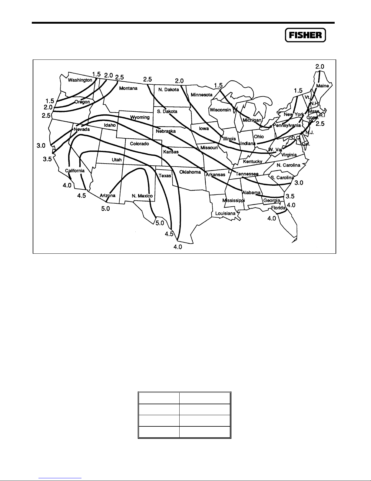
To determine solar panel output requirements, first determine the solar insolation for your geographic
area. The map in Figure 1-3 shows solar insolation (in hours) for the United States during winter
months. Call your local Fisher Representative for a map detailing your specific geographic area.
Insolation (from map) = _____ hours
Next, calculate the amount of current required from the solar array per day using the following
equation. ISF is the system current requirement. Refer to Section 1.7.3 on page 1-16.
= [I
I
array
(amps) × 24 (hrs)]/Insolation (hrs) = _____ amps
SF
Finally, the number of solar panels can be determined using the following equation:
Number of Panels = I
Rev 2/01 1-17
array
amps/(I
amps/panel) = _____ panels
panel
Page 22
General Information
Figure 1-3. Solar Insolation in Hours for the United States
NOTE
The “I
” value varies depending on the type of solar panel installed. Refer to
panel
the vendor’s specifications for the solar panel being used.
For example, if I
equals 0.54 amps, and I
array
equals 0.29 amps for a 5-watt panel, then the number
panel
of panels required equals 1.86, which would be rounded up to 2 (panels connected in parallel).
Alternatively, the next larger solar panel can be used, which in this case would be a 10-watt panel.
Table 1-2 gives I
values for solar panels recommended by Fisher Controls.
panel
Table 1-2. Solar Panel Sizing
Panel I
panel
4.5 watt 0.27 amps
5 watt 0.29 amps
10 watt 0.58 amps
1-18 Rev 2/01
Page 23

EF-Series Instruction Manual
1.7.5 Batteries
In solar installations, batteries provide power for the EF-Series Unit whenever the solar panels are not
generating sufficient output.
The standard battery configurations use a 12-volt, sealed, lead-acid battery (approximately 6.0 x 2.6 x
3.7 inches). These configurations can provide 7, 14, 21, or 28 amp-hour capacities. Recommended 7
amp-hour battery types (up to four batteries) for EF-Series Units are listed below. If other batteries are
used, Fisher Controls recommends rechargeable, sealed, gel-cell, lead-acid batteries.
♦
Powersonic PS-1270 7.0 Amp-Hour
♦
Panasonic LCR12V7.2P 7.2 Amp-Hour
♦
Yuasa NP7-12 7.0 Amp-Hour
The batteries are connected in parallel by a supplied wiring harness to achieve the required capacity.
The amount of battery capacity required for a particular installation depends upon the power
requirements of the equipment and days of reserve (autonomy) desired. Battery requirements are
calculated based on power consumption of the EF-Series Unit and all devices that will be powered by
the batteries.
Battery reserve is the amount of time that the batteries can provide power without discharging below
20 percent of their total output capacity. For solar-powered units, a minimum reserve of five days is
recommended, with ten days of reserve preferred. Add 24 hours of reserve capacity to allow for
overnight discharge. Space limitations, cost, and solar panel output are all factors that affect the actual
amount of battery capacity available.
To determine the system capacity requirements, multiply the system current load (ISF) on the batteries
by the amount of reserve time required. Compute “ISF” as described in Section 1.7.3, Totaling Power
Requirements. The equation is as follows:
System Requirement = I
amps × Reserve hrs = _____ amp-hrs
SF
Finally, determine the number of batteries required for the calculated power consumption by rounding
up to the nearest multiple of 7 amps: 7, 14, 21, or 28 amp-hour capacity. If more than 28 amp-hours
are required, an external battery enclosure with additional batteries may be used.
Rev 2/01 1-19
Page 24

General Information
1.8 STARTUP AND OPERATION
Before starting the EF-Series Unit, perform the following checks to ensure the unit is properly
installed.
♦
Make sure the enclosure has a good earth ground connected to the earth ground bus inside the
enclosure.
♦
Check the field wiring for proper installation. Refer to Section 2.
♦
Make sure the input power has the correct polarity.
♦
Make sure the input power is fused at the power source.
CAUTION
It is important to check the input power polarity before turning on the power.
Incorrect polarity can damage the EF-Series Unit.
CAUTION
When installing equipment in a hazardous area, ensure that all components are
approved for use in such areas. Check the product labels.
1.8.1 Startup
Apply power to the EF-Series Unit by plugging the input power terminal block into the connector
labeled POWER located at the bottom left of the Main Electronics Board. After the EF-Series Unit
completes start-up diagnostics (RAM and other internal checks), the LCD displays the date and time to
indicate that the EF-Series Unit completed a valid reset sequence. If the LCD does not come on, refer
to the Troubleshooting and Repair paragraphs in Section 2 for possible causes.
1.8.2 Operation
Once startup is successful, it is necessary to configure the EF-Series Unit (see Section 2.6 for more
information) to meet the requirements of the application. The ROCLINK User Manual provides
detailed information for using the ROCLINK software to configure the EF-Series Unit and to calibrate
its I/O (see Section 2.7 for more information about calibration). Once the EF-Series Unit is configured
and calibrated, it can be placed into operation.
CAUTION
Local configuration or monitoring of the EF-Series Unit through its LOI port must
be performed only in an area known to be non-hazardous.
During operation, the EF-Series Unit can be monitored (to view or retrieve current and historical data)
either locally or remotely. Local monitoring is accomplished either by viewing the LCD panel detailed
in Section 2.4.3, or by using ROCLINK on a PC connected through the LOI port (see the ROCLINK
User Manual). Remote monitoring is normally performed through the host port of the EF-Series Unit,
using the eFlow Internet Measurement Services (IMS).
1-20 Rev 2/01
Page 25

EF-Series Instruction Manual
SECTION 2 — USING THE EF-SERIES UNIT
2.1 SCOPE
This section describes the EF-Series flow computer, focusing on how it works and how to connect
wiring. Major topics include:
♦
Product Functions
♦
Product Electronics
♦
Connecting the Wiring
♦
Configuration
♦
Calibration
♦
Troubleshooting and Repair
♦
Specifications
2.2 SECTION CONTENTS
This section contains the following information:
Information Section Page Number
Product Functions 2.3 2-3
Flow Measurement 2.3.1 2-3
History Points 2.3.2 2-4
Security 2.3.3 2-6
Power Control 2.3.4 2-6
Report By Exception (RBX) Alarming 2.3.5 2-7
Product Electronics 2.4 2-8
Main Electronics Board Overview 2.4.1 2-8
Microprocessor and Memory 2.4.2 2-8
Liquid Crystal Display 2.4.3 2-10
Communications Ports 2.4.4 2-10
Built-In Discrete Output 2.4.5 2-11
RTD Input 2.4.6 2-12
Real-Time Clock 2.4.7 2-12
Diagnostic Monitoring 2.4.8 2-12
Automatic Self Tests 2.4.9 2-12
Low Power Modes 2.4.10 2-13
Connecting the EF-Series unit to Wiring 2.5 2-15
Making Wiring Connections 2.5.1 2-15
Connecting Ground Wiring 2.5.2 2-16
Connecting Main Power Wiring 2.5.3 2-17
Auxiliary Output Power 2.5.4 2-21
Rev 2/01 2-1
Page 26

Using the EF-Series Unit
Information Section Page Number
RTD Wiring 2.5.5 2-21
Discrete Output Wiring 2.5.6 2-23
Connecting Communications Wiring 2.5.7 2-24
Sensor Wiring 2.5.8 2-25
Configuration 2.6 2-26
Calibration 2.7 2-27
Troubleshooting and Repair 2.8 2-28
Backup Procedure Before Removing Power 2.8.1 2-28
Resetting the EF-Series Unit 2.8.2 2-29
After Installing Components 2.8.3 2-33
Replacing the Main Electronics Board 2.8.4 2-33
Sensor Replacement 2.8.5 2-35
Specifications 2.9 2-35
2-2 Rev 2/01
Page 27

EF-Series Instruction Manual
2.3 PRODUCT FUNCTIONS
This section describes the functions of the eFlow EF-Series flow computer, most of which is determined by firmware. The features provided by the firmware, much of which must be configured by
using the ROCLINK configuration software, are:
♦
Flow calculations for an orifice meter.
♦
Archival of data for up to 15 history points.
♦
Memory logging of 240 alarms and 240 events.
♦
Security with local and remote password protection.
♦
Power cycling control for a radio.
♦
Report-by-exception (RBX) capability.
2.3.1 Flow Measurement
The primary function of the EF-Series Unit is to measure the flow of natural gas through an orifice in
accordance with the 1992 American Petroleum Institute (API) and American Gas Association (AGA)
standards. The flow calculation is in accordance with ANSI/API 2530-92 (AGA Report No. 3 1992),
API Chapter 14.2 (AGA Report No. 8 1992 2nd printing 1994), and API Chapter 21.1. The flow
calculation may be configured for either Metric or English units.
The primary inputs used for the orifice metering flow measurement function are differential pressure,
static pressure, and temperature. The differential and static pressure inputs, which are sampled once
per second, come from the Flow Sensor. The temperature input, which is sampled and linearized once
per second, comes from an RTD probe.
Flow Time
The differential pressure stored for each second is compared to the configured low flow cutoff. If the
differential pressure is less than or equal to the low flow cutoff or the converted static pressure is less
than or equal to zero, flow is considered to be zero for that second. Flow time for a recalculation
period is defined to be the number of seconds for which the differential pressure exceeded the low flow
cutoff.
Input and Extension Calculation
Every second the EF-Series unit stores the measured input for differential pressure, static pressure, and
temperature and calculates the flow extension (defined as the square root of the absolute upstream
static pressure times the differential pressure).
Flow time averages of the inputs and the flow extension over the configured recalculation period are
calculated unless there is no flow for an entire recalculation period. If there is no flow, averages of the
inputs are recorded to allow monitoring during no flow periods.
Rev 2/01 2-3
Page 28

Using the EF-Series Unit
Instantaneous Rate Calculations
The instantaneous value of the flow extension is used with the previous recalculation period’s Integral
Multiplier Value (IMV) to compute the instantaneous flow rate. The IMV is defined as the value
resulting from the calculation of all other factors of the flow rate equation not included in the Integral
Value (IV). The IV is defined as the flow extension. The instantaneous flow rate is used with the
volumetric heating value to compute the instantaneous energy rate.
Flow and Energy Accumulation
The averages of the differential and static pressure, temperature, and flow extension are used with the
flow time to compute the flow and energy over the recalculation period. The flow and energy are then
accumulated and stored at the top of every hour. At the configured contract hour, the flow and energy
are then stored to the Daily Historical Log and zeroed for the start of a new day.
2.3.2 History Points
A total of fifteen history points may be logged and accessed in the EF-Series unit. The first eight are
pre-configured for flow metering history and cannot be changed. They are as follows:
♦
Flowing Minutes Today (Accumulate archive type)
♦
Differential Pressure (Average)
♦
Static or Line Pressure (Average)
♦
Temperature (Average)
♦
IMV, Integral Multiplier Value, or C Prime (Average)
♦
Pressure Extension or IV, Integral Value (Average)
♦
Instantaneous Flow (Accumulate)
♦
Instantaneous Energy (Accumulate)
History Point 2, History Point 3, History Point 4, and History Point 6 are all set up as an Average
Archive Type that employs one of the following techniques:
♦
Flow dependent time-weighted linear averaging (default selection)
♦
Flow dependent time-weighted formulaic averaging.
♦
Flow-weighted linear averaging.
♦
Flow-weighted formulaic averaging.
For the history points above, the averaging technique is selected by using ROCLINK. In the Meter
menu, select Setup, then select Inputs. In the Inputs screen, select the desired Averaging Technique.
The selected technique will then be applied to the meter inputs.
The seven user-configurable history points may be configured as described in the ROCLINK User
Manual (see Configure - History).
2-4 Rev 2/01
Page 29

EF-Series Instruction Manual
2.3.2.1 Minute Historical Log
The EF-Series unit has a 60-minute historical log for every history point. The Minute Historical Log
stores the last 60 minutes of data from the current minute. Each history point has Minute Historical
Log entries associated with it.
2.3.2.2 Hourly Historical Log
The EF-Series unit has a total of 840 hourly historical logs available for every history point. The
Hourly Historical Log is also called the Periodic Log. The Hourly Log is recorded every hour at the
top of the hour. The time stamp for periodic logging consists of the month, day, hour, and minute.
2.3.2.3 Daily Historical Log
The EF-Series unit has a total of 35 daily historical logs for every history point. The Daily Log is
recorded at the configured contract hour every day with a time stamp that is the same as the Hourly
Log. Each history point has daily historical log entries.
2.3.2.4 Alarm Log
The Alarm Log contains the change in the state of any signal that has been enabled for alarms. The
system Alarm Log has the capacity to maintain and store up to 240 alarms in a “circular” log (where
the oldest log is in effect overwritten by the newest). The alarm log has information fields which
include time and date stamp, alarm clear or set indicator, and either the tag of the point which was
alarmed along with its current value or a 14 ASCII character description.
In addition to providing functionality for appending new alarms to the log, it allows host packages to
request the index of the most recently logged alarm entry. Alarm logging is available internally to the
system and to external host packages. Alarm Logs are not stored to the flash ROM during the
ROCLINK Save Configuration function.
The Alarm Log operates in a circular fashion with new entries overwriting the oldest entry when the
buffer is full. The alarm log provides an audit history trail of past operation and changes. The Alarm
Log is stored separately to prevent recurring alarms from overwriting configuration audit data.
2.3.2.5 Event Log
The event log contains changes to any parameter within the EF-Series unit made through the native
protocol. This event log also contains other EF-Series unit events such as power cycles, cold starts,
and disk configuration downloads.
The system event log has the capacity to maintain and store up to 240 events in a circular log. The
event log has information fields which include point type, parameter number, time and date stamp,
point number if applicable, the operator identification, and either the previous and current parameter
values or a 14-byte detail string in ASCII format.
Rev 2/01 2-5
Page 30

Using the EF-Series Unit
In addition to providing functionality for appending new events to the log, it allows host packages to
request the index of the most recently logged event entry. Event logging is available internally to the
system and to external host packages.
Event logs are not stored to flash ROM when the Save Configuration function is issued in the
ROCLINK Configuration Software. The event log operates in a circular fashion with new entries
overwriting the oldest entry when the buffer is full. The event log provides an audit trail history of
past operation and changes. The event log is stored separately to prevent recurring alarms from
overwriting configuration audit data.
2.3.3 Security
The EF-Series unit provides for security within the unit. A maximum of 16 log-on identifiers (IDs)
may be stored. In order for the unit to communicate, the log-on ID supplied to the ROCLINK
Configuration Software must match one of the IDs stored in the EF-Series unit. The Operator
Interface port (Security on LOI) has security Enabled by default. The host port Comm1 can likewise
be configured to have security protection, but is disabled by default. Refer to the ROCLINK software
user manual concerning the device security in the ROC menu.
2.3.4 Power Control
The Power Control function (called Radio Power Control in the ROCLINK software) is used with the
RS-232 communications card to provide power savings when using a radio or cell phone for
communications. Two modes of Power Control are possible: Second and Minute. In Second mode,
the time base for the timers is in 100 millisecond increments and is primarily used with radios. In
Minute mode, the time base for the timers is in 1 minute increments and is primarily used with cell
phones. Three cycling zones are provided (see Table 2-1 below for eFlow defaults), but zones can be
disabled as desired. The RS-232 card provides the switching mechanism by means of contacts (see
Section 3.5.1) or the DTR signal.
The Power Control function calculates which zone should be currently active. In Second mode, the
Power Control begins in the ON state and continues with a full On Time and then goes to the OFF state
for the full Off Time. In Minute mode, the Power Control determines if it should be ON or OFF and
how much time it needs until it switches.
2-6 Rev 2/01
Page 31

EF-Series Instruction Manual
Table 2-1. Power Control Defaults
Zone Parameters Default Value
Zone 1, Start Time 400
Zone 1, On 60 Min
Zone 1, Off 0 Min
Zone 2, Start Time 700
Zone 2, On 20 Min
Zone 2, Off 10 Min
Zone 3, Start Time 1700
Zone 3, On 5 Min
Zone 3, Off 15 Min
Hold Time 1 Min
2.3.5 Report By Exception (RBX) Alarming
The RBX functionality, also called Alarm Call-in, allows a communications port to be set up to enable
the EF-Series unit to spontaneously contact the host computer (in a non-polled mode) when specified
alarm conditions exist. To configure RBX, use ROCLINK to set up the desired alarms on individual
points (such as an Analog Input) for RBX; in addition, enable the RBX Mode for the flow computer’s
Comm1 port and configure the RBX Features.
Rev 2/01 2-7
Page 32

Using the EF-Series Unit
2.4 PRODUCT ELECTRONICS
This section describes the EF-Series Main Electronics Board. For Communications Cards, see Section
3. For the Flow Sensor, see Section 4.
2.4.1 Main Electronics Board Overview
The Main Electronics Board components support the functionality of the EF-Series unit. Refer to
Figure 2-1. The board provides:
♦
32-bit microprocessor
♦
Built-in static RAM
♦
Flash ROM
♦
Liquid Crystal Display (LCD) display
♦
Communications card host port
♦
Operator interface port
♦
Built-in Discrete Output (DO)
♦
RTD input
♦
Diagnostic monitoring
♦
Real-time clock and backup power
♦
Automatic self tests
♦
Power regulation modes
2.4.2 Microprocessor and Memory
The EF-Series unit derives processing power from a 32-bit microprocessor. The 32-bit CMOS microprocessor features dual 32-bit internal data buses and a single 8-bit external data bus. The unit can
address up to four megabytes of memory including high-speed direct memory access.
The Main Electronics Board has 512 Kbytes of static random access memory (SRAM) for storing
interrupt vectors, alarms, events, and history data.
The Main Electronics Board also has a 512 Kbyte flash memory chip for storing the operating system
factory code and configuration parameters. Two of the 64 Kbyte blocks are reserved for internal
usage.
2-8 Rev 2/01
Page 33

EF-Series Instruction Manual
LCD
Super
Capacitor
"Battery"
Reset
Jumper (P1)
Comm Card
Connector
Power Wiring
Terminal Block
Sensor Connector
Rev 2/01 2-9
Built-in I/O
Terminal
Blocks
Figure 2-1. Main Electronics Board
Page 34

Using the EF-Series Unit
2.4.3 Liquid Crystal Display
A two-line Liquid Crystal Display (LCD) panel is mounted on the Main Electronics Board. The panel
has automatic contrast adjustment due to temperature sensing and bias adjustment circuitry on the
Main Electronics Board.
The LCD panel remains on at all times when the power applied is in the valid operating range. The
panel cycles its display through a configured list of up to 16 parameter values. The first two displays,
which cannot be configured by the user, show values for time and date, operating voltages, and battery
condition. The next five displays are configured by the factory to show certain flow parameters, but
you may change their configuration. Refer to the ROCLINK User Manual for details on how to
configure the list of values for the LCD panel.
2.4.4 Communications Ports
The EF-Series unit provides two communication ports:
♦
Local Operator Interface port – LOI.
♦
Host port for communication to eFlow host – COM1.
2.4.4.1 Operator Interface Port – LOI
The Operator Interface port, also called the Local Operator Interface (LOI) port, provides direct
communications between the EF-Series unit and the serial port of an operator interface device
(normally an IBM-compatible PC). The interface allows you to access the EF-Series unit (using the
ROCLINK Configuration Software) for configuration and transfer of stored data. The LOI terminal
plus the RTS terminal on the Main Electronics Board provide wiring access to a built-in EIA-232 serial
interface, which is capable of 19.2k baud operation. The operator interface port supports only ROC
protocol communications. The LOI also supports the log-on security feature of the EF-Series unit if
the Security on LOI is Enabled in ROCLINK.
A cannon-type waterproof connector on the bottom of the enclosure provides connection through a
prefabricated cable (available from Fisher) for an operator interface device, typically an IBMcompatible personal computer (PC) running the ROCLINK Configuration Software. Inside the EFSeries unit enclosure, the cannon-type connector is wired to three terminals (LOI) on the Main
Electronics Board.
2.4.4.2 Host Port – COM1
The host port (also called the COM1 port) is activated by the installation of a communications card,
normally an RS-232 serial card. The host port is used to monitor or alter the EF-Series unit from a
remote site using a host or the ROCLINK Configuration Software. The host port automatically
configures itself based upon the specific communications card installed. The host port supports baud
rates up to 19.2K. The COM1 also supports the log-on security feature of the EF-Series unit if the
Security on COM1 is Enabled in ROCLINK.
2-10 Rev 2/01
Page 35

EF-Series Instruction Manual
The host port can receive messages in ROC protocol and will respond in kind. The host port is capable
of initiating a message in support of Report by Exception (RBX) and Store and Forward when using
ROC protocol. Refer to the ROCLINK Configuration Software User Manual.
For installations using radio communications, battery power can be conserved by cycling power to the
radio or cellular telephone. The power cycling control is achieved through the EIA-232 communications card. The radio or cell phone is connected to terminals located on the EIA-232 communications
card, as described in Section 3. For configuration, refer to the Radio Power Control function in the
ROCLINK Software User Manual.
The communications connectors on the Main Electronics Board provide the EF-Series unit with
electrical access and mounting provisions for the optional communications cards. The
communications card mounts directly on the connectors at P3 on the Main Electronics Board and is
held in place with three compression stand-offs. The stand-offs on the Main Electronics Board pass
through the communications card. The communications cards available for the EF-Series unit allow
the options of serial data communication and modem communications. Refer to Section 3.
2.4.5 Built-In Discrete Output
The EF-Series unit provides a discrete output (DO) to provide control capabilities for a sampler or
odorizer. The discrete output is capable of switching up to 0.3 amp of current. Refer to Table 2-2.
Table 2-2. Discrete Output
Output voltage during ON state Battery voltage - 0.7 volts
Output voltage during OFF state 0 volts
Output Current 0.3 amp maximum
Maximum voltage 22 volts maximum - clamping occurs
The built-in discrete output on the EF-Series unit is intended to perform sampler functions, but may be
used as a standard DO. This includes toggle mode, latched mode, and timed DO mode. The discrete
output is accessed by the configuration software as DO Point A4.
When the Sampler function is enabled, the EF-Series unit provides a time duration output (TDO) based
on the volume. A control volume and a pulse duration must be specified with the Sampler function.
After each flow calculation, an internal volume accumulator is compared to the control volume. If the
accumulator exceeds the control volume, a pulse is output and the accumulator is reduced by the
control volume. This output may be used to drive an external totalizer, odorizer, gas sampler, or
similar device.
Rev 2/01 2-11
Page 36

Using the EF-Series Unit
2.4.6 RTD Input
The EF-Series unit supports a direct input from a Resistance Temperature Detector (RTD) sensor. The
terminals for the RTD wires are located at the bottom right of the Main Electronics Board and labeled
“RTD.” Refer to Figure 2-1. The RTD input is converted through a 16-bit RTD converter chip.
During operation, the RTD is read once per second. The value from the RTD is linearized, and then it
is sent to processing as Analog Input (AI) Point Number A3. The AI routine converts this value to
engineering units, performs calibration corrections, and checks alarming. The board temperature is
monitored by the RTD routine; if the temperature has changed by roughly 5° C or 9° F, the RTD
circuitry is sent a command to recalibrate its reference.
2.4.7 Real-Time Clock
The real-time clock provides the EF-Series unit with the time of day, month, year, and day of the week.
The time chip automatically switches to backup power when the Main Electronics board loses primary
input power. Backup power for the real-time clock comes from a supercapacitor (which also backs up
the non-volatile RAM), and is adequate for at least three weeks with no power applied to the EF-Series
unit.
2.4.8 Diagnostic Monitoring
The electronics board has three diagnostic inputs incorporated into the circuitry for monitoring battery
voltage, charging voltage, and board temperature. These inputs can be accessed by using the I/O
function of the ROCLINK Configuration Software. The three values are available as the following
Analog Input (AI) points:
♦
E1– battery voltage
♦
E2 – input/charging voltage
♦
E5 – board temperature
2.4.9 Automatic Self Tests
The EF-Series unit performs the following self tests on a periodic basis:
♦
Battery low and battery high.
♦
Software and hardware watchdog.
♦
RTD automatic temperature compensation.
♦
Sensor operation.
♦
Charging voltage for the supercapacitor.
♦
Memory validity.
The EF-Series unit operates with 6 to 15 volts of dc power. The LCD becomes active when input
power with the proper polarity and startup voltage (typically set at 10.6 volts or greater) is applied to
the POWER terminal block (provided the power input fusing/protection is operational). The battery
voltage tests ensure that the unit is operating in the optimum mode.
2-12 Rev 2/01
Page 37

EF-Series Instruction Manual
The software watchdog is controlled by the Main Electronics Board. This watchdog checks the
software for validity every 1.2 seconds. If necessary, the software is automatically reset. The
hardware watchdog is controlled by the Main Electronics Board and monitors the power to the
hardware. If this voltage drops below 4.75 volts, the unit is automatically shut down.
RTD automatic temperature compensation is tested at approximately every 5 degrees Celsius temperature change of the board temperature.
The EF-Series unit monitors its orifice-metering Sensor for accurate and continuous operation.
Voltage for charging the supercapacitor is checked to ensure that it is continuously applied when the
EF-Series unit is powered.
A memory validity self-test is performed to ensure the integrity of memory.
2.4.10 Low Power Modes
The processor used in the EF-Series unit is capable of low power operation under predetermined
conditions. These features are available because of the Phase Lock Loop (PLL) used to control the
speed of the system clock. The base crystal frequency is 3.6863 MHz and is raised by the PLL to 14.7
MHz for normal system operation. During the low power modes, the PLL and oscillator are in various
states of shutdown. Two low power modes are supported: Standby and Sleep (also called Doze).
♦
Standby — This mode is used during periods of inactivity. When the operating system cannot
find a task to run, the EF-Series unit enters Standby mode. Processor loading is calculated by
using the amount of time spent in Standby mode. This mode keeps the clocks running and
communications active with baud clocks running. A Periodic Interrupt Timer (PITR) wakes up
the EF-Series unit and starts the normal operating mode.
Wake-up from Standby occurs when the EF-Series unit receives a:
♦
Timed / Alarmed interrupt from the Real-Time Clock.
♦
Signal from the Operator Interface port – LOI.
♦
Signal from Connector P10 (built-in I/O) or I/O card
♦
Signal Carrier Detect (CD) from a communications board – COM1.
♦
Signal Ring Indicator (RI) from a communications board – COM1.
♦
Sleep — This mode is used if a low battery voltage is detected. The battery voltage measured
by diagnostic input point E1 is compared to the low-low alarm limit associated with this point.
This limit value defaults to 10.6 volts.
Wake-up from Sleep occurs when the EF-Series unit receives a:
♦
Timed / Alarmed interrupt from the Real-Time Clock.
♦
Signal from the Operator Interface port – LOI.
Rev 2/01 2-13
Page 38

Using the EF-Series Unit
If the battery voltage is less than the low-low alarm limit configured for point E1, the unit:
1.
Sets the Real-Time Clock (RTC) alarm for 15 minutes from the present time if a charge
voltage (point E2) is greater than the battery voltage (point E1), or for 55 minutes if the
charge voltage is less than the battery voltage.
2.
Writes the message “Low Battery, Sleep Mode” to the LCD.
3.
Enters the Sleep mode.
4.
Shuts down communications.
5.
The unit wakes up from Sleep mode by the Real-Time Clock alarm (set in Step 1) and
rechecks the voltage to see if operation is possible. If the voltage is greater than the
low-low alarm limit for point E1, a normal restart sequence initiates.
2-14 Rev 2/01
Page 39

EF-Series Instruction Manual
2.5 CONNECTING THE EF-SERIES UNIT TO WIRING
The following paragraphs describe how to connect the EF-Series unit to power, ground, I/O devices,
and communications devices. Use the recommendations and procedures described in the following
paragraphs to avoid damage to equipment.
The field wiring terminations are accessed by opening the front door. The wiring terminals are
arranged on the lower edge of the Main Electronics Board. The terminal designations are printed on
the circuit board (see Figure 2-1 on page 2-9).
This section includes:
♦
Making Wiring Connections
♦
Connecting Ground Wiring
♦
Connecting Main Power Wiring
♦
RTD Wiring
♦
Discrete Output Wiring
♦
Connecting Communications Wiring
♦
Sensor Wiring
CAUTION
Always turn the power to the EF-Series unit off before you attempt any type of
wiring.
CAUTION
To avoid circuit damage when working with the unit, use appropriate electrostatic
discharge precautions, such as wearing a grounded wrist strap.
2.5.1 Making Wiring Connections
The Main Electronics Board connectors use compression terminals that accommodate wiring up to #16
AWG in size. The input power terminations use a removable connector and accommodate wiring up
to #14 AWG in size. In all cases, connections are made by baring the end (¼ inch maximum) of the
wire, inserting the bared end into the clamp beneath the termination screw, and then tightening the
screw.
The inserted wires should have a minimum of bare wire exposed to prevent short circuits. Allow some
slack when making connections to prevent strain on the circuit board and to provide enough clearance
to allow the Main Electronics Board to swing out. This allows access to the batteries without removal
of the field wiring.
Rev 2/01 2-15
Page 40

Using the EF-Series Unit
The following connectors are provided on the Main Electronics Board:
♦
Battery Input – POWER, BAT
♦
Charge Input – POWER, CHG
♦
Auxiliary Radio Power – RADIO
♦
Flow Sensor – P/DP
♦
Discrete Output – DO
♦
Resistance Temperature Detector – RTD
♦
Operator Interface port – LOI
♦
Communications card connector – P3
The input terminal wiring is arranged on the lower edge of the Main Electronics Board. The terminal
designations are printed along the bottom of the circuit board as shown in Figure 2-1 on Page 2-9.
2.5.2 Connecting Ground Wiring
The EF-Series flow computer and related components must be connected to an earth ground. The
National Electrical Code (NEC) governs the ground wiring requirements for all line-powered devices.
Refer to Section 1 for further details.
There is a ground bar located inside the enclosure at the top right-hand side. This ground bus bar is
electrically bonded to the enclosure and provides screw compression terminals to connect shields from
I/O wiring, line-power earth ground, and other device earth grounds as needed.
An external lug on the bottom outside of the enclosure (refer to Figure 2-2) provides a place to connect
an earth ground to the enclosure. Although this ground lug is electrically connected to the ground bar
through the enclosure, it is recommended that a ground wire also be connected between the ground lug
and the ground bar.
It is recommended that 14 AWG wire be used for the ground wiring. Make sure the installation
has only one ground point to prevent creation of a ground loop circuit. A ground loop circuit could
cause erratic operation of the system.
The Main Electronics Board is electrically isolated from the enclosure; no earth ground connections to
the board should be made. However, the drain shields of I/O signal wiring (such as the RTD cable)
should be connected to earth ground at one end to minimize signal errors caused by EMI
(electromagnetic interference), RFI (radio frequency interference), and transients.
CAUTION
Do not connect the earth ground to any terminal on the Main Electronics Board.
2-16 Rev 2/01
Page 41

EF-Series Instruction Manual
ground
Figure 2-2. Earth Ground Connection
Earth Ground
2.5.3 Connecting Main Power Wiring
It is important that good wiring practice be used when sizing, routing, and connecting power wiring.
All wiring must conform to state, local, and NEC codes. The POWER terminal block can
accommodate up to 14 AWG wire. Refer to Figure 2-3.
Up to 15 volts
To make power connections:
1.
Unplug the left-hand connector from its socket located at P8 on the Main Electronic Board.
2.
Insert each bared wire end into the clamp beneath its termination screw.
Figure 2-3. Power Input Terminal Connector
Up to 22 volts
3.
Secure the screw.
4.
Plug the connector back into the socket at P8.
Rev 2/01 2-17
Page 42

Using the EF-Series Unit
As described in sections 2.5.3.1 and 2.5.3.2, connect the batteries (if used) to the “+BAT” and “BAT-”
terminals. Connect the charging source (normally a solar panel) to the “+CHG” and “CHG-”
terminals. Make sure the hook-up polarity is correct.
NOTE
If you are connecting a solar panel that has its own regulator, connect the panel
instead to the +BAT and BAT- terminals.
2.5.3.1 Battery Connections
The battery connections are on the removable terminal block labeled POWER. Refer to Figure 2-4.
These connections provide the input power for the electronics and are also the output of the charge
regulation circuitry. A single 12-volt, sealed, lead-acid battery or multiple batteries wired in parallel
are connected to these terminals, which are labeled “+BAT” for battery positive and “BAT-” for battery
negative.
CAUTION
The maximum voltage that can be applied to the “BAT” terminals without damage
to the electronics is 15 volts dc.
The EF-Series unit enclosure can hold up to four sealed lead-acid batteries; see Section 1.7.5 for
recommended battery types. The 12-volt batteries can be installed to give 7, 14, 21, or 28 amp-hours
of backup capacity.
The batteries are mounted under the electronics swing-out mounting panel and are retained by the
panel when it is secured. The batteries are connected to a harness that allows the batteries to be
changed without removing power from the unit. Make sure that the black wires of the harness are
connected to the negative terminals of the batteries and that the red wires are connected to the positive
terminals. Input wiring is connected at the POWER wiring terminal connector.
2-18 Rev 2/01
Page 43

EF-Series Instruction Manual
Swing-out Panel
Figure 2-4. Battery and Solar Panel Connections
Rev 2/01 2-19
Page 44

Using the EF-Series Unit
2.5.3.2 Solar Panel Charge Connections
The EF-Series unit contains an internal battery charger circuit for charge control of the 12-volt
batteries. The charger monitors the battery voltage, charge voltage, and the battery temperature, which
is actually the board enclosure temperature. Based on these three conditions, a charge rate is
determined and applied to the battery. Refer to Figure 2-4 for the proper wiring connections.
NOTE
The internal battery charger limits the current input to 1 amp, which is less than
the output of a typical 22-watt solar panel. To use a solar panel with an output
exceeding 1 amp, ensure that the panel has its own regulator and is connected to the
+BAT and BAT- terminals.
NOTE
Keep in mind that a solar panel bigger than 11 watts may violate certain CSA
Class I, Division 2 ratings. Be sure to use approved connectors on the bottom of the
EF-Series enclosure for routing the power wiring.
NOTE
If the solar panel contains its own regulator, connect it instead to the +BAT and
BAT- terminals.
The charging source (solar panel) provides power for the charging of the backup batteries. Overcharging is prevented by comparing the battery cell voltage to a maximum limit. If this limit is
exceeded, the battery charge cycle is immediately terminated and cannot be re-initiated until the cell
voltage has dropped below the maximum limit.
The charge connections (+CHG and CHG-) are on the removable connector labeled POWER. These
connections provide the input voltage and power for the battery charging circuitry. The charger
circuitry provides reverse polarity protection and reverse discharge protection, so no external circuitry
is required. The maximum voltage that can be applied to the terminals is 22 volts dc. The terminals
are labeled CHG+ for charge input positive and CHG- for charge input negative.
A 12-volt solar panel with an output regulated to no more than 15 volts can be directly connected to
the +BAT and BAT- terminals.
2-20 Rev 2/01
Page 45

EF-Series Instruction Manual
2.5.4 Auxiliary Output Power
The auxiliary output power connections are on a fixed terminal block connector labeled RADIO.
Refer to Figure 2-5. These terminals can supply power (pass-through) to external devices such as a
radio. The power for this connector originates at the battery connection terminal and is not fused or
controlled on the Main Electronics Board. Fusing should be installed in the auxiliary output wiring
and should not exceed the size of the fuse in the battery harness wiring. The terminals are labeled “+”
for positive voltage and “-” for common.
Radio or other constantpowered device
Figure 2-5. Auxiliary Power Terminals
If power to the radio or other device needs to be cycled to conserve power (recommended when
batteries are used), use an EIA-232 communications card and connect wiring for switched radio power
as described in Section 3. Configure Radio Power Control as detailed in the ROCLINK Configuration
Software User Manual.
2.5.5 RTD Wiring
The temperature is input through the Resistance Temperature Detector (RTD) probe and circuitry. An
RTD temperature probe mounts directly to the piping using a thermowell, outside the EF-Series
enclosure. RTD wires should be protected either by a metal sheath or conduit connected to a liquidtight conduit fitting on the bottom of the enclosure. The RTD wires connect to the four screw
terminals designated “RTD” on the Main Electronics Board. Refer to Figure 2-6.
The EF-Series unit provides terminations for a four-wire 100-ohm platinum RTD with a DIN 43760
curve. The RTD has an alpha equal to 0.00385. A three-wire or two-wire RTD probe can be used
instead of a four-wire probe; however, they may produce measurement errors due to signal loss on the
wiring.
Wiring between the RTD probe and the EF-Series unit must be shielded wire, with the shield grounded
only at one end to prevent ground loops. Ground loops cause RTD input signal errors.
Rev 2/01 2-21
Page 46

Using the EF-Series Unit
4-Wire RTD
3-Wire RTD
2-Wire RTD
The RTD terminals on the Main Electronics Board are designated and defined as follows:
♦ “REF” current source reference
♦ “+” signal positive input
♦ “-” signal negative input
♦ “RET” return (common) reference
Red
Red
RedRed
Figure 2-6. RTD Wiring Terminal Connections
Jumper
Red
Red
RTD Sensor
As shown in Figure 2-6, the connections at the RTD terminals for the various RTD probes are as
follows:
Terminal 4-Wire RTD 3-Wire RTD 2-Wire RTD
REF Red Jumper to + Jumper to +
+ Red Red, Jumper to REF Red, Jumper to REF
– White White White, Jumper to RET
RET White White Jumper to –
2-22 Rev 2/01
Page 47

EF-Series Instruction Manual
p
2.5.6 Discrete Output Wiring
A discrete output is provided on the Main Electronics Board in the P10 terminal block. Refer to Figure
2-7. The typical application for this output is a sampler or odorizer control, although it may be used
for other purposes.
The DO uses a P-channel MOSFET to switch current-limited (300 mA) battery power to the positive
terminal. The negative terminal is internally connected to battery negative. A blocking diode, a 22volt transorb, and a back-EMF diode are included to protect the flow computer electronics.
Because the output is not isolated, care must be used to ensure that the operation of the load does not
affect the operation of the EF-Series unit. This may include installation of back-EMF diodes and
MOVs on the load. The load should be connected as follows:
♦
DO + Positive load
♦
DO - Negative load
Figure 2-7. Discrete Output Terminal Wiring
Rev 2/01 2-23
Odorizer,
Sam
le Valve…
Page 48

Using the EF-Series Unit
2.5.7 Connecting Communications Wiring
The EF-Series unit communicates to external devices through its communication ports. Communications take place either through the operator interface port (LOI) or the host port (COM1). A
special 3-pin connector provides a port for an operator interface device. Wiring connections for the
host port are made using screw terminals on the installed communications card.
2.5.7.1 Operator Interface Port Wiring
Figure 2-8 displays the operator interface (LOI) port located at P10 on the Main Electronics Board.
The LOI port provides connections for a built-in EIA-232 communications interface to a configuration
and monitoring device. The configuration and monitoring device typically is an IBM-compatible
personal computer. A prefabricated operator interface cable is available as an accessory from Fisher.
The LOI port is intended for use with the ROCLINK Configuration Software. This LOI port is
compatible with RS-232 levels. The port signals originate on the Main Electronics Board terminations
and are wired to the three-terminal, cannon-style LOI connector located on the bottom of the
enclosure. An RTS terminal is provided on the Main Electronics Board (not routed to the cannon
connector) and is intended for future applications, such as using the LOI port as a second host port.
The following table shows the signal routing of the Main Electronics Board terminations and the
cannon-style connector:
Main Board Cannon Connector Signal
BLK 1 Common
WHT 2 RXD
RED 3 TXD
2-24 Rev 2/01
Page 49

EF-Series Instruction Manual
Red (TX)
White (RX)
Black
(Common)
Common
RX
TX
Connection at
PC Serial Port
Figure 2-8. Operator Interface Wiring
2.5.7.2 Host Port Wiring
The host port provides communications access to the EF-Series unit through a communications card at
COM1. Section 3 details the types of communications cards available for the EF-Series unit and how
to make wiring connections to each one.
2.5.8 Sensor Wiring
For information on Flow Sensor wiring, refer to Section 4 of this manual.
Rev 2/01 2-25
Page 50

Using the EF-Series Unit
2.6 CONFIGURATION
IMPORTANT NOTE: For configuration purposes, the eFlow EF-Series flow computer
is equivalent to the FloBoss 503 Flow Manager. References in the ROCLINK software
or ROCLINK manual to the FloBoss 500-Series or FB503 generally apply to the EFSeries unit, with the exclusion of I/O Card points, PID Control, and FSTs.
The EF-Series Flow Computer has a number of software settings, called parameters, that must be
configured before it is calibrated and placed into operation. Configuration must be performed using
the ROCLINK configuration software, which runs on an IBM-compatible personal computer. The
personal computer is normally connected to the LOI port of the flow computer to transfer
configuration data into the EF-Series unit, although much of the configuration can be done off-line
and later loaded into the unit.
The configuration data can be loaded into the flow computer while it is either in the office or in the
field. Although configuration changes can be made remotely via the host port, it is not recommended
except for minor changes, due to the possibility of data being corrupted during transmission.
Default values for all parameters exist in the firmware of the flow computer. If the default is
acceptable for your application, it can be left as it is. At a minimum, the following items should be
checked and configured as needed:
♦
Meter Setup and Gas Quality – use Quick Setup in the ROCLINK File menu
♦
Clock – can use Quick Setup
♦
History points (check Averaging Technique on History Points 2, 3, 4, and 6; see Section 2.3.2)
♦
AI points 1 to 3 for Sensor and RTD (High/Low Reading EU, scanning enabled, alarm setup,
and such.)
♦
Comm Ports (especially Comm1 – use Comm Ports item in ROC menu)
♦
Power Control (see Section 2.3.4 for defaults, etc.)
♦
Security (see Section 2.3.3)
♦
RBX (if alarm call-in is needed; see Section 2.3.5)
♦
LCD User List (for local display of additional values)
2-26 Rev 2/01
Page 51

EF-Series Instruction Manual
2.7 CALIBRATION
The calibration routines (performed by the configuration software) support 5-point calibration, with
two end points and three mid-points. The low-end or zero reading is calibrated first, followed by the
high-end or full-scale reading. The three mid-points, if desired, can be calibrated next. The diagnostic
analog inputs—battery voltage (E1), charge voltage (E2), and board/battery temperature (E5)—are not
designed to be calibrated.
The built-in inputs that are supported for 5-point calibration are the first three Analog Input points:
♦
Differential pressure located at AI Point A1
♦
Static pressure located at AI Point A2
♦
RTD temperature located at AI Point A3
Since two of the three points are obtained from the Flow Sensor, the calibration procedure for these
inputs is described in Section 4.
Rev 2/01 2-27
Page 52

Using the EF-Series Unit
2.8 TROUBLESHOOTING AND REPAIR
Troubleshooting and repair procedures are designed to help you identify and fix problems with the
Main Electronics Board and communications cards. Contact your Fisher Representative before you
attempt to remove a suspected faulty board or card for repair or replacement. To troubleshoot
communications cards, refer to Section 3.
The following items may be needed for troubleshooting:
♦
IBM-compatible personal computer.
♦
ROCLINK Configuration Software.
The ROCLINK Configuration Software runs on the personal computer and is required for a majority of
the troubleshooting performed on the EF-Series unit. Refer to the ROCLINK Configuration Software
User Manual for additional information.
2.8.1 Backup Procedure Before Removing Power
Use the following backup procedure when removing or adding components. This procedure preserves
the current flow computer configuration and log data held in RAM.
Before removing power to the EF-Series unit for repairs, troubleshooting, or upgrades, perform this
backup procedure.
CAUTION
When working on units located in a hazardous area (explosive gases may be
present), make sure the area is in a non-hazardous state before performing
these procedures.
CAUTION
To avoid circuit damage when working inside the unit, use appropriate
electrostatic discharge precautions, such as wearing a grounded wrist strap.
1.
Launch the ROCLINK Configuration Software.
2.
Ensure that the configuration is saved in flash memory by performing a Write to Internal
Config Memory (use the ROC Flags screen accessed from the ROC menu). This saves all
configuration settings, including the current states of the ROC Flags and calibration values.
3.
If you will be replacing the flash chip, save the current configuration data to disk by using the
Save function in the File menu. This action saves the configuration to an .fcf file (you can
specify your own file name and path if desired).
4.
Select Collect Data from the ROC menu. Ensure the All box is checked and click OK. This
action saves event logs (.evt), alarm logs (.alm), report data (.det), hourly logs (.pdb), and daily
(.day) logs (you can specify your own file name and path if desired).
2-28 Rev 2/01
Page 53

EF-Series Instruction Manual
2.8.2 Resetting the EF-Series Unit
If you are experiencing problems with the EF-Series unit that appear to be software related, try resetting
the EF-Series unit. As described in the following paragraphs, there are three ways to reset the unit:
♦
Warm S ta rt .
♦
Cold Start.
♦
Jumper Reset.
For example, if security was enabled on both communication ports of the EF-Series unit, the settings
were saved to permanent memory, and then the ID and/or Passwords were lost, communications with
the EF-Series unit will be locked out on both ports until a Jumper Reset is performed; then the host
port could be used, since its security is disabled by default.
If none of these methods seem to help, the EF-Series unit may need to be returned to the factory for
repair. Contact your Fisher Representative.
2.8.2.1 Warm Start
This re-initialization is performed by setting a parameter in the System Flags. The re-initialization
includes the Tasks, Database, Communication Ports, Sensor, and I/O. This does not change the current
configuration of any parameters. Refer to Figure 2-9.
1.
Launch the ROCLINK Configuration Software.
2.
Go to the ROC Flags screen.
3.
Set the Warm Start flag.
4.
Apply or save the change.
Rev 2/01 2-29
Page 54

Using the EF-Series Unit
Figure 2-9. ROC Flags
Alternately, you can perform a warm start by removing power from the EF-Series unit and then
restoring it. Make sure that jumper P1 on the Main Electronics Board is in the NORM position for a
warm start to take place.
2-30 Rev 2/01
Page 55

EF-Series Instruction Manual
2.8.2.2 Cold Start
This re-initialization is performed by setting a parameter in the System Flags, called Cold Start
Options. The re-initialization includes the Tasks, Database, Communication Ports, Sensor, I/O, and
restoring the saved configuration if there is one. It also includes other items, based upon the selection
made in the Options screen shown in Figure 2-10.
Figure 2-10. Cold Start Options
1.
Launch the ROCLINK Configuration Software.
2.
Perform the Backup Procedure in Section 2.8.1.
3.
Select the ROC Flags screen, and select the Cold Start flag.
4.
Click the Cold Start Options pushbutton.
5.
Select the type of Cold Start you desire. Select “Restore Config and Clear All of above” to
reset all options.
6.
Click OK.
7.
Apply or save the change.
Rev 2/01 2-31
Page 56

Using the EF-Series Unit
2.8.2.3 Jumper Reset
The Main Electronics Board has a jumper located at P1 in the upper right-hand corner that can be used
to perform a special type of cold start. Refer to Figure 2-11. This jumper permits a power-up reset to
re-establish a known operating point. The includes reinitializing the Tasks, Database, Communication
Ports, Sensor, and I/O and restoring the factory default configuration. This cold start does not include
any of the clearing options available in a Cold Start performed by using ROCLINK (see Section
2.8.2.2).
CAUTION
This type of reset restores the factory configuration defaults. Some user-entered
configuration parameters may be lost; therefore, try to back up any needed data
before performing this reset.
P1
NORM
RST
DOC0277U
Figure 2-11. Reset Jumper Shown in Normal Position
1.
Refer to Section 2.8.1 and perform the Backup Procedure.
2.
Disconnect the Power terminal block to remove power.
3.
Install the P1 jumper in the reset (RST) position.
4.
Apply power by plugging in the Power terminal block at P8.
5.
Remove the P1 jumper and install it in the normal (NORM) position.
6.
Refer to Section 2.8.3 and perform the After Installing Components procedure.
This reset action loads the factory default values into all configurable parameters.
2-32 Rev 2/01
Page 57

EF-Series Instruction Manual
2.8.3 After Installing Components
After removing power to the EF-Series unit and installing components as needed, perform the
following steps to start your EF-Series unit and reconfigure your data. The procedure assumes you are
using the ROCLINK Configuration Software.
CAUTION
Ensure all input devices, output devices, and processes remain in a safe state
upon restoring power.
CAUTION
When working on units located in a hazardous area (explosive gases may be
present), make sure the area is in a non-hazardous state before performing
these procedures.
1.
Reconnect power to the EF-Series unit by inserting the Power terminal plug into the P8 Power
connector.
2.
Launch the ROCLINK Configuration Software, log in, and connect to the flow computer.
3.
Verify that the configuration is correct. If it is not, continue by configuring the needed items.
If major portions or the entire configuration needs to be reloaded, perform the remaining steps.
4.
Select Download from the File menu.
5.
From the Open dialog box, select the backup configuration file (has extension *.FCF).
6.
Select the portions of the configuration you want to download (restore).
7.
Click on Download to restore the configuration.
2.8.4 Replacing the Main Electronics Board
The Main Electronics Board in the EF-Series flow computer is not intended to be replaced by the enduser. Contact your Fisher Representative or sales office, who will arrange for its repair and
replacement as necessary. For reference purposes only, the replacement procedure is as follows:
CAUTION
There is a possibility of losing the device configuration and historical data
while performing the following procedure. As a precaution, save the current
configuration and historical data as instructed in Section 2.8.1.
When installing units in a hazardous area, make sure installation
components selected are labeled for use in such areas. Installation and
maintenance must be performed only when the area is known to be nonhazardous.
Rev 2/01 2-33
CAUTION
Page 58

Using the EF-Series Unit
To avoid circuit damage when working with the unit, use appropriate
electrostatic discharge precautions, such as wearing a grounded wrist strap.
During this procedure, all power will be removed from the EF-Series unit and
any devices powered by it. Ensure that all connected input devices, output
devices, and processes remain in a safe state when power is removed from the
EF-Series unit and also when power is restored.
1.
Refer to Section 2.8.1 on page 2-28 for the Backup Procedure Before Removing Power.
2.
Disconnect the Power input connector at P8 from the Main Electronics Board.
3.
Remove the communications card by carefully pulling or prying the card loose from the lower
compression stand-offs first, the upper compression stand-off next, and finish by unplugging
the card from its mating connector. Disconnect wiring from the communications card as
needed to clear the way for removing the Main Electronics Board.
CAUTION
CAUTION
4.
Label and remove all wiring connected to the Main Electronics Board.
5.
Remove the Main Electronics Board from the five compression stand-offs securing the card,
and lift the board out of the case. You may need to carefully pry the board off the stand-offs if
you are unable to loosen the board by hand.
6.
Install the new Main Electronics Board in the case. Firmly press the board over the
compression stand-offs to secure the board to the case. The compression stand-offs “snap” into
place when the card is secured.
7.
Reconnect wiring removed in Step 4, and re-install the communications card removed in Step
3.
8.
Plug the Main Electronics Board Power wiring into socket P8.
9.
Refer to Section 2.8.3, After Installing Components.
2-34 Rev 2/01
Page 59

EF-Series Instruction Manual
2.8.5 Sensor Replacement
Damaged or faulty Sensor units must be returned to the factory for repair. To maintain the approval
rating of the EF-Series unit, this replacement procedure should be performed only by a certified agent.
1.
Refer to Section 2.8.1 on page 2-28 for the Backup Procedure Before Removing Power.
2.
Disconnect the POWER input connector at P8 from the Main Electronics Board.
3.
Disconnect the P/DP input terminal connector from the Main Electronics Board.
4.
Remove the four bolts holding the Sensor in place.
5.
Return the Sensor to your Fisher Representative.
6.
Position the new or repaired Sensor, ensuring gasket is in place, and install the four bolts to
secure the Sensor.
7.
Reconnect the P/DP ribbon cable connector to the Main Electronics Board.
8.
Refer to Section 2.8.3, After Installing Components.
2.9 SPECIFICATIONS
Refer to the following pages for specifications of the main electronics board. For Sensor
specifications, refer to Section 4.
Rev 2/01 2-35
Page 60

Using the EF-Series Unit
Main Specifications
PROCESSOR INFORMATION
Motorola 32 bit, running at 14.7 MHz.
Program Memory:
programmable) for firmware and configuration.
Data Memory:
backed for up to 4 weeks.
Memory Reset:
initialization when used during power-up.
TIME FUNCTIONS
Clock Type:
supply, super capacitor-backed. Year/Month/Day and
Hour/Minute/Second, with Daylight Savings Time control.
Clock Accuracy:
Watchdog Timer:
second and resets the processor.
DIAGNOSTICS
These conditions are monitored and alarmed: SRAM
validity/operation, Sensor and RTD point fail, battery and
charging voltages, internal temperature.
COMMUNICATIONS
Operator Interface:
Software configured, 600 to 19.2K baud rate selectable.
Screw-cap protected connector.
Host:
communications card is installed.
POWER
Battery Input:
up). 0.2 W typical, including Sensor power, but excluding power for discrete output load and communications
card.
Charging Input:
limited to 1.0 amp.
LOCAL DISPLAY
2 line by 16 character LCD. Continually updates
approximately every 3 seconds. See Environmental
specification for operating temperature.
FLOW SENSOR (BUILT-IN)
See Specifications table in Section 4.
RTD INPUT (BUILT-IN)
Quantity/Type:
element.
Terminals:
input, “-” signal negative input, and “Ret” return
(common).
32 kHz crystal oscillator with regulated
Serial or modem interface, when optional
“Ref” current source, “+” signal positive
512 Kbyte flash ROM (electrically
512 Kbyte SRAM, super capacitor-
A reset jumper enables a cold start
0.01%.
Hardware monitor expires after 1
EIA-232 (RS-232D) format.
8 to 15 Vdc (normally 10.8 Vdc to start
14 to 22 Vdc. Charge current internally
Single input for a 2, 3, or 4-wire RTD
RTD INPUT (BUILT-IN) (CONTINUED)
Sensing Range:
Accuracy:
(includes linearity, hysteresis, repeatability).
Ambient Temperature Effects per 28° C (50° F):
±0.50° C (.90° F) for process temperatures from -40
to 100° C (-40 to 212° F).
Band-pass hardware filter.
Filter:
Resolution:
Conversion Time:
Sample Period:
DISCRETE OUTPUT (BUILT-IN)
Quantity/Type:
output.
Terminals:
(common).
Voltage:
0.7 volts.
Frequency:
Sample Period:
Current Limit:
ENVIRONMENTAL
Operating Temperature:
°F), excluding LCD display, which is -25 to 70 °C
(-13 to 158 °F).
Storage Temperature:
°F).
Operating Humidity:
Vibration:
an abbreviated endurance dwell test.
Radiated/Conducted Transmissions:
with requirements for Class A Information Technology Equipment per EN 55022 (1995) and
CISPR 22 (1993). Also complies with FCC Part 15
Class A.
Voltage Surge Immunity:
801-4 and IEC 801-5, as required by EN 50082-2.
ENCLOSURE
Construction:
steel with lockable hasp and gasketed door.
Coating is light gray polyurethane paint. All
unpainted hardware is stainless steel. Meets CSA
Type 4 rating (NEMA 4 equivalent).
Wiring access:
in bottom.
Same as applied to Battery Input minus
-50 to 100° C (-58 to 212° F).
±0.56° C (1.0° F) over sensing range
16 bits.
100 µsec.
1 sec minimum.
1 sourced, high-side switched
“+” positive output, “-” negative
1.5 Hz maximum.
200 ms minimum.
300 mA, automatic reset.
-40 to 75 °C (-40 to 167
-50 to 85 °C (-58 to 185
5 to 95%, non-condensing.
Tested to SAMA 31.1 Condition 3, with
Complies
Designed to meet IEC
Powder-coated 14-gauge carbon
Three 0.88 in. pre-punched holes
2-36 Rev 2/01
Page 61

EF-Series Instruction Manual
Main Specifications (Continued)
DIMENSIONS
Overall:
(457 mm by 350 mm by 184 mm). Height includes
top mounting flange and Sensor.
Wall Mounting:
by 350 mm) between mounting hole (0.38 in.
diameter) centers.
Pipestand Mounting:
U-bolt mounting kit (supplied).
18.12 in. H by 13.80 in. W by 7.25 in. D
2.81 in. W by 13.80 in. H (72 mm
Mounts on 2-inch pipe with
WEIGHT
28.5 lb (13.0 kg) nominal, including Sensor and coupler,
but excluding batteries (not supplied).
APPROVALS
Approved by CSA as W40079 controller for
hazardous locations Class I, Division 2, Groups A,
B, C, and D.
Rev 2/01 2-37
Page 62

Using the EF-Series Unit
2-38 Rev 2/01
Page 63

EF-Series Instruction Manual
SECTION 3 — COMMUNICATION CARDS
3.1 SCOPE
This section describes the communication cards used with the eFlow EF-Series Flow Computer.
Topics covered include:
♦
Product Descriptions
♦
Initial Installation and Setup
♦
Connecting the Communication Cards to Wiring
♦
Troubleshooting and Repair
♦
Specifications
3.2 SECTION CONTENTS
This section contains the following information:
Information Section Page Number
Product Descriptions 3.3 3-2
EIA-232 Serial Communications Card 3.3.1 3-3
Power Cycling 3.3.1.1 3-4
EIA-485 Serial Communications Card 3.3.2 3-5
Dial-up Modem Communications Card 3.3.3 3-6
Initial Installation and Setup 3.4 3-8
Installing Communications Cards 3.4.1 3-8
Connecting Communications Cards to Wiring 3.5 3-10
EIA-232 Communications Card Wiring 3.5.1 3-10
Auxiliary Power Wiring 3.5.1.1 3-10
EIA-485 Communications Card Wiring 3.5.2 3-11
Dial-Up Modem Communications Card Wiring 3.5.3 3-12
Troubleshooting and Repair 3.6 3-13
Replacing a Communications Card 3.6.1 3-13
Communication Cards Specifications 3.7 3-15
Serial Card Specifications 3.7.1 3-15
Dial-up Modem Card Specifications 3.7.2 3-16
Rev 2/01 3-1
Page 64

Communication Cards
3.3 PRODUCT DESCRIPTIONS
The communications cards provide communications between the EF-Series unit and the Internet host
system provided by the eFlow Internet Measurement Services powered by Aurion. The communications cards install directly onto the Main Electronics Board at P3 and activate the host port (Comm1)
when installed. The following cards are available:
♦
EIA-232 Serial Communications Card (standard)
♦
EIA-485 Serial Communications Card (optional)
♦
Dial-up Modem Communications Card (optional)
3-2 Rev 2/01
Page 65

EF-Series Instruction Manual
3.3.1 EIA-232 Serial Communications Card
The EIA-232 communications card meets all EIA-232 specifications for single-ended, RS-232
asynchronous data transmission over distances of up to 50 feet. Refer to Figure 3-1. The EIA-232
communications card provides transmit, receive, and modem control signals. Normally, not all of the
control signals are used for any single application.
This is the standard communications card for the host port of the EF-series Unit. The EIA-232
communication card’s P1 connector plugs into the Main Electronics Board at P3 and activates Comm1.
The RTS and DTR control lines are supported. The EIA-232 communications card defaults are: 9600
baud rate, 8 data bits, 1 stop bit, no parity, 10 millisecond Key-On Delay, and 10 millisecond Key-Off
Delay. If you need to change any of these default values, use the ROCLINK software. The maximum
baud rate allowed by the software is 19.2k.
The EIA-232 communications card includes LED indicators that display the status of the RXD, TXD,
DTR, DCD, and RTS signal/control lines. LED indicators are detailed in Table 3-1.
Power Control
Mating Connector
Host Port (Comm1)
Terminals
Figure 3-1. EIA-232 Serial Communications Card
Rev 2/01 3-3
DOC0274A
Page 66

Communication Cards
Table 3-1. Communications Cards LED Indicators
LEDs STATUS AND ACTIVITY
AA
The AA is the automatic answer indicator LED light. An incoming modem
transmission lights this indicator.
DCD The DCD data carrier detect LED lights when a valid carrier tone is detected.
DTR
The DTR data terminal ready LED lights when a signal from the processor
specifies the device is ready to answer an incoming transmission. When the DTR
goes off, a connected device disconnects.
OH
The OH is the off hook indicator LED light. A dial tone has been detected and the
telephone line is in use by your modem when OH is lit.
RTS The RTS ready to send LED lights when a signal from the processor specifies the
modem is ready to transmit.
RXD The RXD receive data LED blinks when the receive signal is being received from
the communications card. The LED is on for a space and off for a mark.
TXD The TXD transmit data LED blinks when transmit signal data is being received
from the processor. The LED is on for a space and off for a mark.
3.3.1.1 Power Cycling
This function is available with the EIA-232 communications card to provide power savings when using
a radio or cell phone for communications. Power cycling control is accomplished through Power
Control Terminals or the DTR signal on the EIA-232 communications card. Connect wiring as
described in Section 3.5.1. Configure power cycling using the Radio Power Control feature as
described in the ROCLINK User Manual.
3-4 Rev 2/01
Page 67

EF-Series Instruction Manual
3.3.2 EIA-485 Serial Communications Card
The EIA-485 communications cards meet EIA-485 specifications for differential, RS-485
asynchronous transmission of data over distances of up to 4000 feet. Refer to Figure 3-2. The EIA485 drivers are designed for true multi-point applications with multiple devices on a single bus.
This is an optional communications card for the host port. The P1 connector on the EIA-485
communication card plugs into the Main Electronics Board at P3, activating Comm1.
The interface lines of RTS are supported to control transmission. RTS must be active during TXD.
The default values for the EIA-485 communications card are: 9600 Baud Rate, 8 Data Bits, 1 Stop Bit,
No Parity, 10 millisecond Key On Delay, and 10 millisecond Key Off Delay. The maximum baud rate
is 19.2k.
The EIA-485 communications card includes LED indicators that display the status of the RXD, TXD,
and RTS control lines. LED indicators are detailed in Table 3-1.
Mating Connector
LEDs
Figure 3-2. EIA-485 Serial Communications Card
Rev 2/01 3-5
Host Terminals – Comm1
Page 68

Communication Cards
3.3.3 Dial-up Modem Communications Card
The dial-up modem communications card supports V.22 bis/2400 baud communications with autoanswer/auto-dial features. Refer to Figure 3-3. The modem card is FCC part 68 approved for use with
public-switched telephone networks (PSTNs). The FCC label on the card provides the FCC
registration number and the ringer equivalent. The modem card has automatic adaptive and fixed
compromise equalization.
This is an optional communications card for the host port. The dial-up modem communications card’s
P1 connector plugs into the Main Electronics Board at P3, activating Comm1.
The defaults for the dial-up modem communications card are: 2400 baud rate, 8 data bits, 1 stop bit,
no parity, 10 millisecond Key On Delay, and 10 millisecond Key Off Delay. On power up, the modem
must be set up for Auto Answer. Periodic checks are made to ensure that the modem is still in Auto
Answer or that it is not left off the hook after a certain period of non-communication.
Mating Connector
Figure 3-3. Dial-up Modem Communications Card
3-6 Rev 2/01
RJ11 Connector
DOC0276A
Page 69

EF-Series Instruction Manual
The modem card interfaces to two-wire, full-duplex telephone lines using asynchronous operation at
data baud rates of 1200 and 2400. The card interfaces to a PSTN through an RJ11 jack located at the
bottom of the communications card. The modem can be controlled using industry-standard AT
command software. A 40-character command line is provided for the AT command set, which is
compatible with EIA document TR302.2/88-08006.
LED indicators on the card show the status of the RXD, TXD, AA, and OH control lines. Refer to
Table 3-1. The modem card also provides RS-232 level output signals (RXD and TXD) for an
analyzer.
Rev 2/01 3-7
Page 70

Communication Cards
3.4 INITIAL INSTALLATION AND SETUP
Communications card installation is normally performed at the factory when the EF-Series unit is
ordered. However, the modular design of the unit makes it easy to change hardware configurations in
the field. The following procedures assume that this is a first-time installation of a communications
card in an EF-Series unit and that the unit is currently not in service. For units currently in
service, refer to the procedures in Section 3.6, “Troubleshooting and Repair.”
CAUTION
When installing units in a hazardous area, ensure that the components selected are
labeled for use in such areas. Change components only in an area known to be nonhazardous.
CAUTION
Be sure to use proper electrostatic handling, such as wearing a grounded wrist
strap, or components on the circuit cards may be damaged.
3.4.1 Installing Communications Cards
All communications cards install into the EF-Series unit in the same manner.
Unplug the Power terminal block at P8 to ensure power is removed.
1.
Plug the communications card connector P1 into connector P3 on the Main Electronics Board.
2.
Figure 3-4 shows the card location. Gently press the connectors together until the card contacts
a stand-off.
Ensuring that the three stand-off holes in the communications card line up with the
3.
compression stand-offs on the Main Electronics Board, firmly press the communications card
onto the stand-offs.
Plug in the Power terminal block at P8 to allow power to be applied.
4.
With the EF-Series unit powered up, and a PC connected to the LOI port and running the
5.
ROCLINK software, ensure that the configuration associated with the communications card is
correct. If not, change as needed.
Perform wiring as instructed in Section 3.5.
6.
3-8 Rev 2/01
Page 71

EF-Series Instruction Manual
Stand-off Hole
Mating
Connector
Communications
Card
Stand-off Hole
Stand-off Hole
Figure 3-4. Communications Card Location
Rev 2/01 3-9
Page 72

Communication Cards
3.5 CONNECTING COMMUNICATIONS CARDS TO WIRING
Signal wiring connections to the communications cards are made through the terminal block located on
the serial communications cards, or through the RJ11 TELCO connector supplied on the modem card.
3.5.1 EIA-232 Communications Card Wiring
The EIA-232 communications card provides for RS232 signals on the host port. This communications
card also provides a means to switch external power to communication devices such as a radio to
conserve power. LEDs are provided for diagnostic functions. The screw terminals and their functions
are as follows:
Terminal Function
RXD Receive data
TXD Transmit data
DTR Data Terminal Ready
RTS Ready to Send
DCD Data Carrier Detect
GND Ground
IN Switched Power input
(Out) Switched power output
3.5.1.1 Auxiliary Power Wiring
Switched auxiliary power is used for radios or other devices that do not have a built-in sleep mode to
automatically shut the device off. Control of auxiliary power is set up by using the Radio Power
Control function of the ROCLINK software to achieve the required power cycling. The switched
method involves wiring the power through the EIA-232 communications card as shown in Figure 3-5.
If the auxiliary device already has a built-in sleep mode, or for some reason you do not need to cycle
the auxiliary power, you can wire directly to the RADIO terminals for power as described in Section 2.
3-10 Rev 2/01
Page 73

EF-Series Instruction Manual
RS232
Comm
Card
Switched Power
+
to Radio or
–
Other Device
Figure 3-5. Wiring Switched Auxiliary Power
3.5.2 EIA-485 Communications Card Wiring
The EIA-485 communications card provides for RS-485 signals on the host port (Comm1). Wiring
should be twisted-pair cable. This board also provides additional protection for the external wiring and
the board circuitry. LEDs are provided for diagnostic functions. The terminals and their functions are
as follows:
Terminal Function
A RS485 positive
B RS485 negative
GND Ground
Rev 2/01 3-11
Page 74

Communication Cards
3.5.3 Dial-Up Modem Communications Card Wiring
The dial-up modem card interfaces to a PSTN line through the RJ11 jack located at J2 with two wires.
The dial-up modem card provides for a telephone interface on the host port that is capable of both
answering and originating phone calls. The dial-up modem card also provides electronics that
conserve power when the phone line is not in use. The dial-up modem card provides some protection
from transients on the phone lines; however, if the potential for lightning damage is high, additional
surge protection for the phone lines should be installed outside the EF-Series enclosure.
LEDs are provided for diagnostic functions. The dial-up modem card provides a modular phone
(RJ11) jack that directly interfaces to phone line connections. The RJ11 conductors and their signals
are:
RJ11 Signal
1
2
3Tip
4Ring
5
6
3-12 Rev 2/01
Page 75

EF-Series Instruction Manual
3.6 TROUBLESHOOTING AND REPAIR
There are no user serviceable parts on the communications cards. If a card appears to be operating
improperly, verify that the card is set up according to the information contained in Section 3.4, “Initial
Installation and Setup.” If it still fails to operate properly, the recommended repair procedure is to
remove and replace the card. The faulty card should be returned to your Fisher Representative for
repair or replacement.
Follow the procedures below to help ensure data is not lost and equipment is not damaged during
replacement of a communications card.
3.6.1 Replacing a Communications Card
If you are installing a communications card for the first time, refer to Section 3.4. To remove and
replace a communications card on an in-service EF-Series unit, perform the following procedure. Be
sure to observe the cautions to avoid losing data and damaging equipment.
CAUTION
When repairing units in a hazardous area, ensure that the components selected are
labeled for use in such areas. Change components only in an area known to be non-
hazardous.
CAUTION
There is a possibility of losing the flow computer’s configuration and historical data
while performing the following procedure. As a precaution, save the current
configuration and historical data as instructed in Section 2.8.1, Backup Procedure.
CAUTION
Be sure to use proper electrostatic handling, such as wearing a grounded wrist
strap, or components on the circuit cards may be damaged.
CAUTION
During this procedure, all power will be removed from the EF-Series unit and
devices powered by the EF-Series unit. Ensure that all connected input devices,
output devices, and processes will remain in a safe state when power is removed
from the unit and also when power is restored.
Rev 2/01 3-13
Page 76

Communication Cards
Refer to Section 2.8.1 and perform the RAM Backup Procedure.
1.
Remove the Power terminal block at P8 on the Main Electronics Board.
2.
If the communications card is a modem card, unplug the RJ11 phone jack cable from the
3.
communications card connector J2.
Using a rocking motion, gently disengage the two stand-off connectors located at the bottom of
4.
the communications card.
Using a rocking motion, gently disengage the stand-off connector located at the top, middle of
5.
the communications card.
Using a rocking motion to disengage the connectors at P1, pull the card free from the Main
6.
Electronics Board at P3.
To reinstall a communications card, orient the card with the P1 connectors on the
7.
communications card mating with the connectors at P3 on the Main Electronics Board. Plug
the card into its mating connectors and gently press until the connectors firmly seat.
Using a rocking motion, gently engage the stand-off connectors.
8.
For a modem card, connect the RJ11 phone jack cable to communications card connector J2.
9.
Reconnect power by plugging in the Power terminal connector at P8 on the Main Electronic
10.
Board.
Check the configuration data, and re-load or modify as required.
11.
Verify that the EF-Series unit performs as required.
12.
Perform the After Installing Components detailed in Section 2.8.3.
13.
If you changed the configuration, save the configuration data to permanent memory. It is also good
practice to save the configuration data to a disk file. See Section 2.8.1 for information on how to
perform these saves.
3-14 Rev 2/01
Page 77

EF-Series Instruction Manual
3.7 COMMUNICATION CARDS SPECIFICATIONS
The following subsections list the specifications for each communications card.
3.7.1 Serial Card Specifications
EIA-232D
CARD
EIA-485
CARD
Meets EIA-232 standard for singleended data transmission over
distances of up to 50 feet (15 m).
Data Rate:
19.2k baud.
Format:
(software selectable) with full
handshaking.
Parity:
(software selectable).
Meets EIA-485 standard for differential data transmission over
distances of up to 4000 feet (1220
meters) for multiple devices.
Data Rate:
19.2k baud.
Format:
(software selectable).
Parity:
(software selectable).
Selectable from 1200 to
Asynchronous, 7 or 8-bit
None, odd, or even
Selectable from 1200 to
Asynchronous, 7 or 8-bit
None, odd, or even
LED
INDICATORS
POWER
REQUIREMENTS
ENVIRONMENTAL
WEIGHT
DIMENSIONS
APPROVALS
Individual LEDs for RXD, TXD,
and RTS signals. EIA-232D card
also has LEDs for DTR and DCD.
4.75 to 5.25 Vdc, 0.03 W maximum (not including radio power),
supplied by processor board.
Operating Temperature:
75 °C (-40 to 167 °F).
Storage Temperature:
°C (-58 to 185 °F).
Operating Humidity:
relative, non-condensing.
0.8 oz. (23 g) nominal.
0.7 in. H by 2.0 in. W by 2.75
in. L (18 by 51 by 70 mm).
Covered by CSA approval for the
unit in which card is installed.
-40 to
-50 to 85
To 95%
Rev 2/01 3-15
Page 78

Communication Cards
3.7.2 Dial-up Modem Card Specifications
OPERATION Mode:
up PSTN (Bell 212 compatible).
Data Rate:
asynchronous (software
selectable).
Parity:
(software selectable).
Format:
including start, stop, and parity
(software selectable).
Modulation:
phase-coherent FSK; V.22 and
212A, 4 point DPSK at 600 baud;
V.22bis, 16 point QAM at 600 baud.
Transmit Carrier Frequencies:
Originate, 1200 Hz ± 0.1%;
Answer, 2400 Hz ± 0.1%.
Receive Carrier Frequencies:
Originate, 2400 Hz ± 7 Hz;
Answer, 1200 Hz ± 7 Hz.
Transmit Amplitude:
typical.
Telephone Line Impedance:
600 ohm typical.
RTS to Transmission Delay:
Configurable in 50 millisecond
periods (software selectable).
Receiver Sensitivity:
threshold, -45 dBm. On to Off
threshold, -48 dBm.
Full-duplex 2-wire for dial-
1200 or 2400 baud
None, odd, or even
8, 9, 10, or 11 bits,
V.21 and 103, binary
-1 dB
Off to On
OPERATION
(CONTINUED)
POWER
REQUIREMENTS
ENVIRONMENTAL
DIMENSIONS
WEIGHT
APPROVALS
Maximum Output Level:
dBm nominal into 600 ohms.
LED Indicators:
AA, and OH.
Connector:
Surge Protection:
FCC part 68 and DOC.
Surge Isolation:
1500 volt peak.
Certification:
approved.
4.5 to 5.5 Vdc, 0.25 W maximum, supplied by processor
board.
Operating Temperature:
75 °C (-40 to 167 °F).
Storage Temperature:
85 °C (-58 to 185 °F).
Operating Humidity:
relative, non-condensing.
0.7 in. H by 2.0 in. W by
2.75 in. L (18 mm by 51 mm
by 70 mm).
1.3 oz. (36 g).
Covered by CSA approval for the
unit in which card is installed.
TXD, RXD,
RJ11 (6-pin).
1000 Vac and
FCC Part 68
0
Conforms to
-40 to
-50 to
To 95%
3-16 Rev 2/01
Page 79

EF-Series Instruction Manual
SECTION 4 — THE FLOW SENSOR
4.1 SCOPE
This section describes the orifice-metering Flow Sensor (also called a DVS or Dual-Variable Sensor),
which provides differential pressure and static pressure inputs to the EF-Series flow computer for the
orifice flow calculation. Note that the Sensor is not equipped to provide a temperature input to the
flow computer; this input comes directly into the unit by means of the built-in RTD input. Refer to
Section 2.
This section contains the following information:
Information Section Page Number
Description 4.2 4-1
Process Connections 4.3 4-2
Sensor Wiring 4.4 4-2
Configuration 4.5 4-3
Calibration 4.6 4-4
Verifying Calibration 4.6.1 4-4
Calibrating the Meter Inputs 4.6.2 4-5
Zero Shift 4.6.3 4-8
Specifications 4.7 4-8
4.2 DESCRIPTION
The orifice-metering Flow Sensor measures differential pressure and static pressure by converting the
applied pressure to electrical signals and making the readings available to the Main Electronics Board.
The sensor housing screws into an adapter, which in turn mounts with four bolts to the bottom of the
EF-Series enclosure. The Sensor cable plugs directly into the Main Electronics Board at the P/DP
connector.
The readings from the Sensor are stored in analog inputs on the EF-Series Unit. The differential
pressure value uses the Analog Input (AI) Point Number A1, and the static pressure value uses the AI
Point Number A2. If the alarm for either point is enabled and the sensor fails to communicate, during
either initialization or operation, an alarm is entered in the Alarm Log.
The Sensor uses an interrupt to inform the Main Electronics Board that it is ready for an update. This
must occur at least once per second. The flow computer then converts this value and stores it in the
proper analog input for access by other functions within the unit. If an update does not occur in the
one second interval, the sensor is re-initialized. A point fail alarm is set if the sensor does not respond
to the initialization.
Rev 2/01 4-1
Page 80

Flow Sensor
4.3 PROCESS CONNECTIONS
Piping from the meter run must be connected to the Flow Sensor of the EF-Series flow computer.
Both the static and differential pressures are piped to female ¼-18 NPT connections on the bottom of
the Sensor. The EF-Series Unit is an upstream device, meaning that the static pressure line normally
must be connected to the high pressure side (labeled “H” on the sensor body).
If you need to use the EF-Series Unit as a downstream device:
Connect the “H” side of the sensor to downstream pressure, so that flow in relation to the
1.
sensor is reversed from its normal direction.
Use ROCLINK to configure the meter run for Downstream operation (this automatically
2.
adjusts the static pressure by adding in the differential pressure).
Calibrate the differential pressure as described in Section 4.6.
3.
4.4 SENSOR WIRING
The EF-Series Unit and its Flow Sensor are shipped from the factory with the wiring connected
between them. This wiring consists solely of a ribbon cable from the Sensor, which is plugged into the
P/DP connector on the Main Electronics Board at P11. This ribbon cable is keyed to fit into the P11
connector in only one direction.
CAUTION
Always turn power off to the flow computer before you connect or disconnect wiring.
4-2 Rev 2/01
Page 81

EF-Series Instruction Manual
4.5 CONFIGURATION
Use ROCLINK Configuration Software to configure the Sensor inputs for an EF-Series Unit.
♦
The differential pressure is configured at Analog Input Point Number A1.
♦
The static pressure (gauge or absolute) is configured at Analog Input Point Number A2.
♦
The Resistance Temperature Detector (RTD) is configured at Analog Input Point Number A3.
The initial pressures are read from the defaults contained within the Sensor. The initial range of the
differential pressure is 0 to 250 inches of water and the static pressure is either 0 to 800 psi (55.15 bar)
or 0 to 3600 psi (250 bar) depending upon the sensor installed. The ranges can be changed through the
calibration routines. It is recommended that the turndown on the range not be greater than what is
given in the Specifications table on Page 4-8.
The Sensor also supports the conversion of values to metric units. In metric mode, both the differential
pressure and the static pressure are in kPa. To set the metric mode, using ROCLINK for Windows
Configuration Software:
Select the ROC menu.
1.
From the pull down menu, select Information.
2.
In the ROC Information window, ensure that the General tab is selected. In the Units area,
3.
click on the Metric radio button.
Click on OK.
4.
To set the metric mode, using ROCLINK (for DOS) Configuration Software:
Select the System menu.
1.
From the pull down menu, select Information.
2.
On the system information display under Units, enable the Metric field.
3.
Press (F8)Save.
4.
The EF-Series Unit automatically adjusts the units, ranges, alarm limits, and calibration factors of the
differential pressure, static pressure, RTD, and enclosure/battery temperature to the Metric mode. To
return to US units, enable the “US” field and save this change to the flow computer. The EF-Series
Unit adjusts the values to US units.
Rev 2/01 4-3
Page 82

Flow Sensor
4.6 CALIBRATION
Calibration is performed using the ROCLINK Configuration Software. The procedure allows you to
perform a 5-point (minimum, maximum, and up to three intermediate points) calibration of the Sensor.
4.6.1 Verifying Calibration
The ROCLINK (for Windows or for DOS) Configuration Software can be used to verify the calibration. This is normally done as a check to see if a re-calibration is needed. To verify, perform the
following steps:
Launch the ROCLINK Configuration Software and connect to the flow computer.
1.
Select the Calibration function from the Meter menu. Alternately, you can select Calibration
2.
from the Quick Setup window (available under File menu). This opens the Meter Calibration
window.
The current reading is shown under each meter input as the Freeze Value. These values will be
3.
used in the flow calculations while the points are being verified. Press the Freeze pushbutton
(not present for Quick Setup Calibration, since in this case freezing is automatic).
CAUTION
To protect the differential cell of the Sensor, open the by-pass valve on the valve
manifold prior to isolating the sensor from the process. This will keep one side of
the differential sensor from being subjected to high pressure while the other side
has no pressure applied. This should be done whether you are calibrating
differential or static pressure. Refer to Figure 4-1 on page 4-6 for the
recommended sequence.
Observing the caution above, apply the desired pressure setting to the input.
4.
Select the Verify pushbutton that is listed under the input to calibrate. This displays the Verify
5.
Calibration dialog box.
If the Tester Value and the Live Reading are to be logged to the Event log as a record of the
6.
verification, select the Log Verify pushbutton. Press Done to return to the Meter Calibration
window.
Repeat the above steps for any other inputs that need to be verified.
7.
Observing the following caution, place the Sensor back in service.
8.
CAUTION
To protect the differential cell of the Sensor, do not close the by-pass valve on the
valve manifold until after process pressure has been reapplied. This will keep one
side of the differential sensor from being subjected to high pressure while the
other side has no pressure applied. Refer to Figure 4-2 on Page 4-7.
4-4 Rev 2/01
Page 83

EF-Series Instruction Manual
When complete, select the OK (or Done) pushbutton to close the Calibration window, to
9.
cancel the freeze values, and to begin using live readings for the flow calculations.
4.6.2 Calibrating the Meter Inputs
The ROCLINK Configuration Software (for Windows or for DOS) is used to perform initial
calibration or re-calibration, such as after an orifice plate is changed in the meter run handled by the
EF-Series Unit.
Perform the following steps:
Launch the ROCLINK Configuration Software and connect to the flow computer.
1.
Select the Calibration function from the Meter menu.. Alternately, you can select Calibration
2.
from the Quick Setup window (available under File menu). This opens the Meter Calibration
window.
The current reading is shown under each meter input as the Freeze Value. These values will be
3.
used in the flow calculations while the points are being verified. Press the Freeze pushbutton
(not present for Quick Setup Calibration since in this case freezing is automatic).
CAUTION
To protect the differential cell of the Sensor, open the by-pass valve on the valve
manifold prior to isolating the sensor from the process. This will keep one side of
the differential sensor from being subjected to high pressure while the other side
has no pressure applied. This should be done whether you are calibrating
differential or static pressure. Refer to Figure 4-1 on page 4-6 for the
recommended sequence.
If you are calibrating a pressure input, read the Caution above, and then isolate the Sensor from
4.
the process. If you are calibrating a temperature input, simply proceed to the next step.
If you are calibrating a pressure input, set up the pressure calibrator and make the necessary
5.
connections to the Sensor. If you are calibrating a temperature input, disconnect the RTD
sensor and connect a decade box (or comparable equipment) to the RTD terminals of the flow
computer.
Select the Calibrate pushbutton under the desired input. This begins the calibration sequence
6.
with the Set Zero dialog box.
Apply the low (zero) value. For a pressure input, this would typically be open to atmosphere.
7.
Enter the applied value in the Dead Weight / Tester field of the Set Zero dialog. For static
8.
pressure on an absolute-pressure device (standard for EF-Series Units), remember to enter the
actual atmospheric pressure, such as 14.73 psi.
Rev 2/01 4-5
Page 84

Flow Sensor
d
LH
LH
High
Pressure
Remains
Close
LH
2
Open
1
Bleed
3
Close
LH
Operating Shutdown Sequence
Shutdn2
Figure 4-1. Removing the Sensor from Service
When the displayed Live Reading is stable, select the Set Zero pushbutton to calibrate the zero
9.
reading. The Set Span dialog box then appears.
Apply the desired lower-end value to the input (the top end of the expected operating range).
10.
To maintain rated accuracy, be sure to observe the turndown limits listed in the Specifications
Table on page 4-8. [If you are calibrating the Diff Press input, and the Sensor is configured for
Downstream operation, be sure to apply the calibrator pressure to the low (labeled “L”) side of
the Sensor; the Live Reading will appear as a negative value. Static pressure for Downstream
is calibrated the same as for Upstream.]
Blee
Enter the applied value in the Dead Weight / Tester field of the Set Span dialog. For static
11.
pressure on an absolute-pressure device, remember to add in the actual atmospheric pressure,
such as 300 + 14.73. [If you are calibrating the Diff Press input, and the Sensor is configured
for Downstream operation, enter the value as positive, even though the Live Reading is a
negative value. The software will automatically compensate.]
When the Live Reading is stable, select the Set Span pushbutton to calibrate the high reading.
12.
The calibration sequence advances to the Set Midpoint 1 dialog box.
If a midpoint (up to three midpoints are possible) is to be calibrated, apply the desired pressure
13.
or temperature and enter the applied value in the Dead Weight / Tester field. Note that the
midpoints can be calibrated in any order. If you are done calibrating, select the Done
pushbutton
When the Live Reading is stable, select the Set Mid pushbutton to calibrate this reading. The
14.
display advances to the next midpoint dialog box.
If additional midpoints are to be calibrated, repeat the above two steps.
15.
When the calibration for a selected point is complete, you have the choice to calibrate another
16.
input or to complete the calibration. If calibration is complete, and you calibrated pressure
inputs, read the following Caution and then return the Sensor to service.
4-6 Rev 2/01
Page 85

EF-Series Instruction Manual
To protect the differential cell of the Flow Sensor, do not close the by-pass valve on
the valve manifold until after process pressure has been reapplied. This will keep
one side of the differential sensor from being subjected to high pressure while the
other side has no pressure applied. Refer to Figure 4-2.
CAUTION
1a
Close
LH
Pre-Startup
start2
1b
Close
LH
Open
LH
4
Close
2
3
Open
Startup Sequence
Figure 4-2. Returning the Sensor to Service
NOTE
If you calibrated the Differential Pressure input, refer to Section 4.6.3, Zero Shift,
before completing the last step.
Finally, select the OK (or Done) pushbutton to cause the calibration window to close,
17.
freeze values to be canceled (unfrozen), and live readings to resume being used for the flow
calculations. All calibration settings that were changed are automatically recorded into the
Event Log of the flow computer.
LH
Rev 2/01 4-7
Page 86

Flow Sensor
4.6.3 Zero Shift
If desired, the Zero Shift procedure can be used after calibrating the differential pressure input. The
reason for performing Zero Shift is due to the fact that the Differential Pressure is calibrated without
line pressure being applied to the sensor. When the sensor is connected back to the process after
calibration, a shift in the differential pressure can occur due to the influence of the line pressure. This
effect can be canceled out with a Zero Shift adjustment.
To check or adjust for Zero Shift, leave the sensor by-pass valve open (to simulate a no-flow
condition), with either line pressure or a normal operating static pressure from the calibrator applied to
the sensor. This applies the same pressure to both sides of the differential pressure diaphragm to give
a zero differential pressure reading.
Perform the following steps:
Ensure the ROCLINK Configuration Software is connected to the flow computer and running
1.
the calibration procedure, with the meter inputs “frozen.”
In the Meter Calibration window, under the Diff Press input, select the Zero Shift pushbutton
2.
to open the Set Zero Shift dialog box.
Check the Live Reading to determine if a Zero Shift correction needs to be performed.
3.
If the reading is not zero, use the Set Zero Shift pushbutton to adjust the Zero Shift. If
4.
adjustment is not needed, use the Done pushbutton. Either way, you are returned to the Meter
Calibration window, where you can select OK (or Done) to close the calibration window,
cancel the freeze values, and cause the flow computer to use live readings for the flow
calculations.
4.7 SPECIFICATIONS
Flow Sensor Specifications
DIFFERENTIAL PRESSURE INPUT
: 0 - 250 in H
Range
Reference Accuracy:
linearity, hysteresis, and repeatability effects) for
spans up to 10:1 turndown.
Stability:
STATIC PRESSURE INPUT
Range:
! 0 - 800 psia (0 -5516 kPa)
! 0 - 3626 psia (0 - 25,000 kPa)
Reference Accuracy:
linearity, hysteresis, and repeatability effects) for
spans up to 6:1 turndown.
Stability:
±0.1% of upper range limit for 12 months.
Absolute pressure measurement:
±0.1% of upper range limit for 12 months.
O (0 - 62.2 kPa)
2
±0.075% of span (includes
±0.075% of span (includes
PROCESS CONNECTIONS
1/4-18 NPT on 2-1/8 inch centers, located on
bottom of Sensor.
CONSTRUCTION
316 SST. Wetted O-rings are glass-filled TFE.
Coupler is stainless steel (CF8M).
ENVIRONMENTAL AND OTHER SPECS
Meets specifications described in the Main
Electronics Specifications table in Section 2.
4-8 Rev 2/01
Page 87

EF-Series Instruction Manual
GLOSSARY OF TERMS
A
A/D — Analog to Digital.
AGA — American Gas Association.
AI — Analog Input.
AO — Analog Output.
Analog — Analog data is represented by a continuous variable, such as a electrical current signal.
AP — Absolute Pressure.
API — American Petroleum Institute.
ASCII — American Standard Code for Information Interchange.
AW G — American Wire Gauge.
B
BTU — British Thermal Unit, a measure of heat energy.
Built-in I/O — Input/Output channels that are fabricated into the ROC or FloBoss and do not require a
separate module. Also called “on-board” I/O.
C
COM1 — Port on the flow computer that is used for host communications.
Configuration — Typically, the software setup of a device that can often be defined and changed by
the user. Can also mean the hardware assembly scheme.
CRC — Cyclical Redundancy Check.
CSA — Canadian Standards Association.
CTS — Clear to Send modem communications signal.
D
D/A — Digital to Analog.
DB — Database.
dB — Decibel. A unit for expressing the ratio of the magnitudes of two electric signals on a
logarithmic scale.
Rev 2/01 G-1
Page 88

Glossary of Terms
DCD — Data Carrier Detect modem communications signal.
Deadband — A value that is an inactive zone above the low limits and below the high limits. The
purpose of the deadband is to prevent a value such as an alarm from being set and cleared
continuously when the input value is oscillating around the specified limit. This also prevents the
logs or data storage location from being over-filled with data.
DI — Discrete Input.
Discrete — Input or output that is non-continuous, typically representing two levels such as on/off.
DO — Discrete Output.
DMM — Digital multimeter.
DP — Differential Pressure.
DSR — Data Set Ready modem communications signal.
DTR — Data Terminal Ready modem communications signal.
Duty Cycle — Proportion of time during a cycle that a device is activated. A short duty cycle
conserves power for I/O channels, radios, etc.
DVM — Digital voltmeter.
DVS — Dual-Variable Sensor. Provides static and differential pressure inputs to a FloBoss 503 Flow
Manager or eFlow EF-Series Flow Computer.
E
EEPROM — Electrically Erasable Programmable Read Only Memory, a form of permanent memory.
EFM — Electronic Flow Measurement.
EIA-232 — Serial Communications Protocol using three or more signal lines, intended for short
distances. Also called RS-232.
EIA-422 — Serial Communications Protocol using four signal lines. Also called RS-422.
EIA-485 — Serial Communications Protocol requiring only two signal lines. Can allow up to 32
devices to be connected together in a daisy-chained fashion. Also called RS-485.
EMF — Electro-motive force.
EMI — Electro-magnetic interference.
ESD — Electro-static discharge.
EU — Engineering Units.
G-2 Rev 2/01
Page 89

EF-Series Instruction Manual
F
Firmware — Internal software that is factory-loaded into a form of ROM. In the ROC, FloBoss, or
EF-Series unit, the firmware supplies the software used for gathering input data, converting raw
input data calculated values, storing values, and providing control signals.
FlashPAC — ROM (and RAM) module that contains the operating system, applications firmware, and
communications protocol in a ROC300-Series unit.
Flash ROM — A type of read-only memory that can be electrically re-programmed. It is a form of
permanent memory (needs no backup power).
FloBoss — A microprocessor-based flow computer that provides remote monitoring and control.
Trademarked by Fisher Controls.
FM — Factory Mutual.
FSK — Frequency Shift Keyed.
FST — Function Sequence Table, a type of program that can be written by the user in a high-level
language designed by Fisher Controls. One or more FSTs can be set up in a ROC or FloBoss.
G
GFA — Ground Fault Analysis.
GND — Electrical ground, such as used by the ROC or flow computer power supply.
GP — Gauge Pressure.
H
HART — Highway Addressable Remote Transducer.
hw — Differential pressure.
I, J
ID — Identification.
IEC — Industrial Electrical Code.
IMS — Internet Measurement Services.
IMV — Integral Multiplier Value.
I/O — Input/Output.
IRQ — Interrupt Request. Hardware address oriented.
IV — Integral Value.
Rev 2/01 G-3
Page 90

Glossary of Terms
K
Kbytes or KB — Kilobytes.
kHz — Kilohertz.
L
LCD — Liquid Crystal Display. Display-only device used for reading data.
LDP — Local Display Panel. A display-only device that plugs into a ROC300-Series unit via a
parallel interface cable. The LDP consists of a 4-line by 20-character alphanumeric display and
four pushbuttons used to access information stored by the ROC.
LED — Light-emitting diode.
LOI — Local Operator Interface. Refers to the serial (RS-232) port on the ROC or flow computer
through which local communications are established, typically for configuration software running
on a PC.
LPM — Lighting Protection Module. Use this module to provide lightning and power surge
protection for I/O on ROC and FloBoss units.
LRC — Longitudinal Redundancy Checking, a type of error checking.
M
mA — Milliamps.
MCU — Master Controller Unit.
MPU — Micro-processor Unit.
MVS — Multi-Variable Sensor. The MVS provides differential pressure, static pressure, and
temperature inputs to the FloBoss 407 (or to a Remote MVS Interface) for orifice flow calculation.
mV — Millivolts, or 0.001 volt.
mW — Milliwatts, or 0.001 watt.
N
NEC — National Electrical Code.
NEMA — National Electrical Manufacturer’s Association.
O
OH — Off-Hook modem communications signal.
G-4 Rev 2/01
Page 91

EF-Series Instruction Manual
Off-line — Accomplished while the target device is not connected (by a communications link). For
example, off-line configuration is configuring a ROC in a electronic file that is later loaded into the
ROC.
Ohms — Units of electrical resistance.
On-line — Accomplished while connected (by a communications link) to the target device. For
example, on-line configuration is configuring a ROC while connected to it, so that current
parameter values are viewed and new values can be loaded immediately.
Opcode — Type of message protocol used by the Fisher ROC or flow computer to communicate with
the configuration software, as well as with host computers.
P, Q
Parameter — A property of a point that typically can be configured or set by the user. For example,
the Point Tag ID is a parameter of an Analog Input point. Parameters are normally edited by using
configuration software running on a PC.
Pf — Flowing pressure.
PC — Personal computer.
P/DP — Pressure/Differential Pressure.
PI — Pulse Input.
PID — Proportional, Integral, and Derivative control feedback action.
PLL — Phase Lock Loop.
Point — Software-oriented term for an I/O channel or some other function, such as a flow calculation.
Points are defined by a collection of parameters.
Point Number — The “rack” and number of an I/O point as located in a ROC or flow computer.
PRI — Primary PID control loop.
PSTN — Public switched telephone network.
PT — Process Temperature.
PTIR — Periodic Timer Interrupt.
PTT — Push-to-talk signal.
Pulse — Transient variation of a signal whose value is normally constant.
PV — Process variable.
Rev 2/01 G-5
Page 92

Glossary of Terms
R
Rack — For a ROC, a rack is a row of slots into which I/O modules may be plugged. The rack is
given a letter to physically identify an I/O channel location, such as “A” for the first rack. Built-in
I/O channels are assigned a rack identifier of “A,” while diagnostic I/O channels are considered to
be in rack “E”.
RAM — Random Access Memory. In a ROC or flow computer, it is used to store history, data, most
user programs, and additional configuration data.
RBX — Report-by-exception. In a ROC or flow computer, it always refers to spontaneous RBX in
which the field device contacts the host to report an alarm condition.
RFI — Radio frequency interference.
RI — Ring Indicator modem communications signal.
ROC — Remote Operations Controller, Fisher Control’s microprocessor-based unit that provides
remote monitoring and control.
ROCLINK — Configuration software used to configure Fisher ROCs or flow computers to gather
data, as well as most other functions.
ROM — Read-only memory. Typically used to store firmware. Flash memory.
RTC — Real-time clock.
RTD — Resistance Temperature Detector.
RTS — Ready to Send modem communications signal.
RTU — Remote Terminal Unit (or Remote Telemetry Unit).
RX or RXD — Received Data communications signal.
S
SAMA — Scientific Apparatus Maker’s Association.
Soft Points — A type of ROC point with generic parameters that can be configured to hold data as
desired by the user.
SP — Static Pressure, or Setpoint.
SPI — Slow Pulse Input.
SPK — Speaker.
SRAM — Static Random Access Memory. Stores data as long as power is applied; typically backed
up by a lithium battery or supercapacitor.
SVA — Signal Value Analog.
SVD — Signal Value Discrete.
G-6 Rev 2/01
Page 93

EF-Series Instruction Manual
T-Z
TDI — Timed Discrete Input, or Timed Duration Input.
TDO — Timed Discrete Output, or Timed Duration Output.
Tf — Flowing temperature.
TLP — Type (of point), Logical (or point) number, and Parameter number.
TX or TXD — Transmitted Data communications signal.
Rev 2/01 G-7
Page 94

Glossary of Terms
G-8 Rev 2/01
Page 95

EF-Series Instruction Manual
INDEX
Numbers
1992 AGA
Flow Calculation .................................................... 2-3
32-bit CMOS Microprocessor..................................... 1-4
A
AA............................................................................... 3-4
Accessing the Battery Compartment......................... 1-14
Accessories.................................................................. 1-6
After Installing Components ..................................... 2-33
AGA ............................................................................ 2-3
Alarm Log ................................................................... 2-5
Alarming
RBX........................................................................ 2-7
Analog Inputs.............................................................. 4-1
Antennas...................................................................... 1-8
API .............................................................................. 2-3
Approvals .................................................................... 1-9
Archive Type............................................................... 2-4
AT Command .............................................................. 3-7
Automatic Self Tests ................................................. 2-12
Auxiliary Output Power ............................................ 2-21
Auxiliary Power ........................................................ 3-10
B
Backup Procedures.................................................... 2-28
After Installing Components ................................ 2-33
BAT ........................................................................... 2-18
Battery......................................................................... 1-6
Accessing the Compartment................................. 1-14
Charger................................................................. 2-20
Charging................................................................. 1-6
Connections.......................................................... 2-18
Requirements........................................................ 1-19
C
Calculations
1992 Flow............................................................... 2-3
Input and Extension................................................ 2-3
Instantaneous Rate.................................................. 2-4
Calibration.......................................................... 2-26, 4-5
I/O Channels......................................................... 1-20
Sensor..................................................................... 4-4
Cathodic Protection.....................................................1-10
Charger...................................................................... 2-20
CHG .......................................................................... 2-18
Class I.......................................................................... 1-9
Clock
Real-Time ............................................................. 2-12
Cold Start................................................................... 2-31
COM1.................................................................1-5, 2-10
Comm Port
Host....................................................................... 2-10
Operator Interface................................................. 2-10
Communication Cards ................................................. 3-1
Communication Ports ................................................ 2-10
Communications
Connectors............................................................ 2-11
Wiring................................................................... 2-24
Communications Cards
Descriptions............................................................ 3-2
Dial-Up Modem...................................................... 3-6
EIA-232 .................................................................. 3-3
EIA-485 .................................................................. 3-5
Installation .............................................................. 3-8
LED Indicators........................................................ 3-4
Location.................................................................. 3-9
Replacing.............................................................. 3-13
Specifications........................................................ 3-15
Troubleshooting.................................................... 3-13
Wiring................................................................... 3-10
Configuration............................................................. 2-26
Flow Sensor ............................................................ 4-3
Verify ......................................................................4-4
Contents................................................................ 3-1, 4-1
D
Daily Historical Logs................................................... 2-5
DC Power Source ...................................................... 2-18
DCD............................................................................. 3-4
Deadband.................................................................... G-2
Diagnostic.................................................................... 1-4
Analog Inputs .......................................................2-26
Diagnostic Inputs....................................................... 2-12
Dial-Up Modem Communications Cards ....3-6, 3-7, 3-14
Specifications........................................................ 3-16
Wiring................................................................... 3-12
Differential Pressure............................. 2-3, 2-4, 4-3, G-5
Dimensions................................................................ 1-13
Discrete Outputs .................................................1-4, 2-11
Wiring................................................................... 2-23
Division 2 .................................................................... 1-9
DO ......................................................................1-5, 2-11
Downstream Usage of Sensor...................................... 4-2
Doze Mode ................................................................ 2-13
DTR ............................................................................. 3-4
Dual-Variable Sensor
Rev 2/01 I-1
Page 96

Topical Index
Description ..............................................................4-1
Duty Cycle ....................................................... 1-15, 1-16
E
E1, E2, and E5............................................................2-12
eFlow EF-Series Flow Computer.................................1-1
EFM .............................................................................1-3
EIA-232 Communications Cards .................................3-3
EIA-485 Communication Cards...................................3-5
Electrical Isolation.......................................................1-10
Electromagnetic Interference .....................................1-10
Electronics Board................................................. 2-1, 2-8
EMF ............................................................................G-2
EMI .................................................................. 1-10, 2-16
Enclosure.............................................................. 1-3, 1-7
Energy ..........................................................................2-4
Energy Accumulation...................................................2-4
Environmental
Requirements...........................................................1-7
Event Log.....................................................................2-6
Extension Calculation ..................................................2-3
F
Field Wiring ...............................................................2-15
Figure 1-1. eFlow EF-Series Flow Computer .............1-4
Figure 1-2. Outline and Mounting Dimensions.........1-13
Figure 1-3. Solar Insolation in Hours for the United
States ........................................................................1-18
Figure 2-1. Main Electronics Board............................2-9
Figure 2-2. Earth Ground Connection.......................2-17
Figure 2-3. Power Input Terminal Connector............2-17
Figure 2-4. Battery and Solar Panel Connections .....2-19
Figure 2-5. Auxiliary Power Terminals.....................2-21
Figure 2-6. RTD Wiring Terminal Connections........2-22
Figure 2-7. Discrete Output Terminal Wiring ...........2-23
Figure 2-8. Operator Interface Wiring.......................2-25
Figure 2-9. ROC Flags ..............................................2-30
Figure 2-10. Cold Start Options ................................2-31
Figure 2-11. Reset Jumper Shown in Normal Position ....
..................................................................................2-32
Figure 3-1. EIA-232 Serial Communications Card.....3-3
Figure 3-2. EIA-485 Serial Communications Card.....3-5
Figure 3-3. Dial-up Modem Communications Card....3-6
Figure 3-4. Communications Card Location...............3-9
Figure 3-5. Wiring Switched Auxiliary Power..........3-11
Figure 4-1. Removing the Sensor from Service..........4-6
Figure 4-2. Returning the Sensor to Service ...............4-7
Firmware .............................................................. 1-5, 2-3
Flash Memory ..............................................................2-8
Flash ROM...................................................................1-4
Flow .............................................................................2-4
Flow and Energy Accumulation...................................2-4
Flow Measurement.......................................................2-3
Flow Sensor................................................................. 4-1
Configuration.......................................................... 4-3
Wiring................................................................... 2-25
Flow Time ................................................................... 2-3
Flowing Minutes.......................................................... 2-4
Functions ..................................................................... 2-3
G
Grid Impedance.......................................................... 1-10
Ground Rod................................................................ 1-10
Grounding
Earth Ground......................................................... 1-10
Ground Wiring...................................................... 2-16
Wiring Requirements............................................ 1-10
Group A....................................................................... 1-9
Group B....................................................................... 1-9
Group C....................................................................... 1-9
Group D....................................................................... 1-9
Groups C, and D.......................................................... 1-9
H
Hardware Watchdog .................................................. 2-13
Hazardous Locations ................................................... 1-9
History Log.................................................................. 2-5
History Points.............................................................. 2-4
Host Port.................................................................... 2-10
Wiring.......................................................... 2-25, 3-10
Hourly Historical Log.................................................. 2-5
I
I/O
Built-in.................................................................... 1-4
I/O Power Requirements ........................................... 1-15
I/O Wiring Requirements .......................................... 1-11
Impedance
Grid....................................................................... 1-10
Input and Extension Calculation.................................. 2-3
Input Terminal Wiring............................................... 2-16
Installation
Communications Cards........................................... 3-8
Guidelines............................................................... 1-7
Startup .................................................................. 1-20
Wiring................................................................... 2-15
Instantaneous Rate Calculations.................................. 2-4
Integral Multiplier Value
IMV ........................................................................ 2-4
Integral Value .............................................................. 2-4
IV............................................................................ 2-4
Isolation ..................................................................... 1-10
J, K
Jumper
Reset ..................................................................... 2-32
I-2 Rev 2/01
Page 97

EF-Series Instruction Manual
L
LCD........................................................................... 2-10
LEDs
Communications Cards .......................................... 3-4
Liquid Crystal Display ....................................... 1-4, 2-10
Local Operator Interface
LOI .........................................................1-5, 1-6, 2-10
LOI Wiring........................................................... 2-24
LOI ............................................................................ 2-10
Low Power Modes .................................................... 2-13
M
Main Electronics Board.................. 1-3, 1-4, 2-1, 2-8, 2-9
Replacing.............................................................. 2-33
MDS .......................................................................... 1-14
Memory....................................................................... 2-8
Metric .......................................................................... 4-3
Microprocessor..................................................... 1-4, 2-8
Minute Historical Log ................................................. 2-5
MOSFET ................................................................... 2-23
Mounting.......................................................... 1-12, 1-13
Radio .................................................................... 1-14
N
National Electrical Code
NEC........................................................................ 1-9
O
OH............................................................................... 3-4
Operation................................................................... 1-20
Operator Interface Port..................................... 2-10, 2-24
LOI .................................................................. 1-5, 1-6
Wiring................................................................... 2-24
Options ........................................................................ 1-6
Orifice-metering Sensor .............................................. 1-5
Overview..................................................................... 1-3
P, Q
P/DP ............................................................................ 4-2
Periodic
Timer Interrupt ............................................. 2-13, G-5
Phase Lock Loop.........................................................G-5
Piping ................................................................. 1-12, 4-2
Polarity.............................................................. 1-20, 2-12
Power
Auxiliary Output - Radio...................................... 2-21
Battery Connections ............................................. 2-18
Before Removing ................................................. 2-28
Charge Connections.............................................. 2-20
Consumption ........................................................ 1-15
Consumption Table............................................... 1-15
Cycling for Radio ................................................... 3-4
I/O Requirements.................................................. 1-15
Low Modes........................................................... 2-13
Main DC ............................................................... 2-18
Operating .............................................................. 2-12
Radio Requirements.............................................. 1-16
Requirements.......................................................... 1-9
Sleep Mode........................................................... 2-13
Solar Power........................................................... 1-17
Standby Mode....................................................... 2-13
Totaling Requirements.......................................... 1-16
Wiring................................................................... 2-17
Power Control.............................................................. 2-6
Power Cycling
Radio..................................................................... 2-21
Pressure ...................................................................... G-5
Pressure Connections................................................... 4-2
Process Connections...........................................1-12, 4-2
Processor ..................................................................... 1-4
Product Overview........................................................ 1-3
Public Switched Telephone Networks
PSTNs..................................................................... 3-6
R
Radio Bracket ..................................................... 1-6, 1-14
Radio Frequency Interference.................................... 1-10
Radio Power .............................................................. 3-10
Radio Power Control ................................................... 2-6
Radio Power Cycling..........................................2-21, 3-4
Radio Power Requirements ....................................... 1-16
Radio Terminal
Auxiliary Output Power........................................ 2-21
RAM............................................................................ 1-4
Backup Procedure................................................. 2-28
RBX Function.............................................................. 2-7
Real-Time Clock......................................2-12, 2-13, 2-14
Rebooting
See Resetting the EF-Series Unit.......................... 2-29
Repair ........................................................................2-28
Replacing
Communications Cards......................................... 3-13
Report by Exception
RBX...................................................................... 2-11
Reset Jumper .............................................................2-32
Resetting the EF-Series Unit .....................................2-29
RFI.................................................................... 1-10, 2-16
ROC/FloBoss Accessories Instruction Manual ...........1-2
ROM
Flash ....................................................................... 1-4
RS232 Communication Card
Wiring................................................................... 3-10
RTD .....................................1-4, 1-5, 2-3, 2-12, 2-13, 4-3
Wiring................................................................... 2-21
RTS.....................................................................2-24, 3-4
RXD............................................................................. 3-4
Rev 2/01 I-3
Page 98

Topical Index
S
Section Contents..........................................................3-1, 4-1
Security.....................................................1-5, 2-6, 2-10, 2-29
Sensor
Calibration .......................................................................4-4
Downstream Usage ........................................................4-2
Orifice-metering.............................................................1-5
Replacement..................................................................2-35
Upstream Usage.............................................................4-2
Wiring...............................................................................4-2
Sensor Wiring.....................................................................2-25
Site Requirements ...............................................................1-8
Sleep Mode.........................................................................2-13
Software Watchdog...........................................................2-13
Solar Arrays
Refer to Solar Panels ...................................................1-17
Solar Panels ..................................................................1-6, 1-8
Power..............................................................................1-17
Sizing..............................................................................1-17
Specifications .....................................................................2-35
Communications Cards...............................................3-15
Dial-Up Modem Communications Cards................3-16
Serial Communications Cards....................................3-15
SRAM....................................................................................1-4
Standby Mode....................................................................2-13
Startup........................................................................1-20, 4-6
Startup and Operation.......................................................1-20
Static Pressure.....................................................2-3, 2-4, 4-3
Static Random Access Memory
SRAM...............................................................................2-8
System Voltage...................................................................1-16
T
Table 1-1. Power Consumption of the EF-Series Unit
and Powered Devices......................................................1-15
Table 1-2. Solar Panel Sizing..........................................1-18
Table 2-1. Power Control Defaults..................................2-7
Table 2-2. Discrete Outputs ............................................2-11
Table 3-1. Communications Cards LED Indicators ......3-4
TDO......................................................................................2-11
Temperature...............................................1-7, 2-3, 2-4, 2-13
Terminal Connections.......................................................2-15
Tests
Automatic ......................................................................2-12
Timer Interrupt .........................................................2-13, G-5
Totaling Power Requirements .........................................1-16
Troubleshooting................................................................2-28
Communications Cards...............................................3-13
Reset...............................................................................2-29
TXD.......................................................................................3-4
Type RL101 ROCLINK Configuration Software User
Manual ................................................................................1-2
U
Units ......................................................................................4-3
V
Vibration...............................................................................1-8
Voltage.................................................................................1-16
W, X
Warm Start..........................................................................2-29
Watchdog
Software and Hardware ...............................................2-13
Wiring..........................................................................2-1, 2-15
Auxiliary Power...........................................................3-10
Battery Connections....................................................2-18
Battery Power Charger................................................2-20
Communications ..........................................................2-24
Communications Cards...............................................3-10
Dial-Up Modem Communications Cards................3-12
Discrete Outputs ..........................................................2-23
EIA-485 Communications Cards ..............................3-11
General...........................................................................2-15
Grounding.....................................................................2-16
Grounding Requirements ...........................................1-10
Host................................................................................3-10
I/O Wiring.....................................................................1-11
Input Terminals.............................................................2-16
LOI..................................................................................2-24
Power..............................................................................2-17
Radio ..............................................................................2-21
RS232 Communications Card ....................................3-10
RTD................................................................................2-21
Sensor ..............................................................................4-2
Wire Gauge...................................................................2-17
Z
Zero Shift..............................................................................4-8
If you have comments or questions about this manual, please contact your Fisher Representative or contact:
FRFC Technical Documentation
c/o Fisher Controls International, Inc.
1612 South 17th Avenue
Marshalltown, Iowa 50158
FAX: 641-754-3630
I-4 Rev 2/01
 Loading...