

Efka SM210A5710 Instruction Manual
Attention!
Parameter numbers
have been changed!
STEPPING MOTOR CONTROL SM210A5710
SM210A5710
KL2359
INSTRUCTION MANUAL
No. 402277 English
FRANKL & KIRCHNER EFKA OF AMERICA INC. EFKA ELECTRONIC MOTORS
GMBH & CO KG SINGAPORE PTE. LTD.


EFKA SM210A57103
CONTENTS Page
1 IMPORTANT SAFETY INSTRUCTIONS 7
2 RANGE OF APPLICATIONS 8
2.1 USE IN ACCORDANCE WITH REGULATIONS 8
3 SCOPE OF SUPPLY 8
3.1 SPECIAL ACCESSORIES 8
4 TECHNICAL DATA OF THE STEPPING MOTOR CONTROL 8
5 CONNECTION SCHEME FOR SM210A 9
5.1 OPERATING THE STEPPING MOTOR CONTROL WITH A SEWING CONTROL (E. G. AB62CV....) 9
6 SOCKET CONNECTORS 10
6.1 POSITION OF THE SOCKET CONNECTORS 10
6.2 CONNECTION DIAGRAM 10
7 STEPPING MOTOR CONTROL FUNCTIONS 13
7.1 STEPPING MOTOR FUNCTION “SYNCHRONOUS OPERATION“ (PA. 290=0) 13
7.1.1 TIMING DIAGRAM “SYNCHRONOUS STEPPING MOTOR OPERATION“ (PA. 290=0) 15
7.2 STEPPING MOTOR FUNCTION “AUTOMATIC METERING D EVICE“ (PA. 290=1 / 2) 16
7.2.1 TIMING DIAGRAM 1 “A UTOMATIC METERING DEVICE“ (PA. 290=1) 18
7.2.2 TIMING DIAGRAM 2 “A UTOMATIC METERING DEVICE AT THE START OF THE SEAM“ (PA. 290=1) 19
7.2.3 TIMING DIAGRAM1 “A UTOMATIC METERING DEVICE AT THE SEAM END“ (PA. 290=2) 20
7.2.4 TIMING DIAGRAM 2 “A UTOMATIC METERING DEVICE AT THE SEAM END“ (PA. 290=2) 21
7.3 STEPPING MOTOR FUNCTION “EXPANDER FEEDING“ (PA. 290=3) 22
7.3.1 TIMING DIAGRAM “EXPANDER FEEDING“ (PA. 290=3) 24
7.3.2 TIMING DIAGRAM “EXPANDER FEEDING/SYNCHRONOUS STEPPING MOTOR OPERATION“ (PA.290=3) 25
7.4 STEPPING MOTOR FUNCTION “FULLNESS SETTING“ (PA. 290=5) 26
7.4.1 TIMING DIAGRAM “FULLNESS SETTING“ (PA. 290=5) 27
7.5 TIMING D IAGRAM “MACHINE FOR ATTACHING CUFF AND HEEL TAPE WITH METERING DEVICE AT
THE SEAM END“ (PA. 290=7) 29
7.5.1 TIMING DIAGRAM “MACHINE FOR ATTACHING CUFF AND HEEL TAPE WITH METERING DEVICE AT THE
SEAM END“ (PA. 290=7) 31
7.6 STEPPING MOTOR FUNCTION “PULLER“ (PA. 290=8 / 9) 32
7.6.1 TIMING DIAGRAM “PULLER“ (P A. 290=8) 34
7.6.2 CONNECTION SCHEME FOR PULLER OPERATION (PA . 290=9) WITH OTHER CONTROLS 35
7.6.3 TIMING DIAGRAM “PULLER“ (P A. 290=9) 37


EFKA SM210A57105
CONTENTS Page
8 PARAMETER LIST 38
8.1 OPERATOR LEVEL 38
8.2 TECHNICIAN LEVEL 39
8.3 SUPPLIER LEVEL 44
8.4 INSERTABLE STRIPS FOR V810/V820 CONTROL PANELS 47

1 Important Safety Instructions
EFKA SM210A57107
When using an EFKA drive and accompanying devices (e g
for sewing machines), basic safety precautions should always
be followed, including the following:
§ Read all instructions thoroughly before using this drive.
§ Drive, its accessories and accompanying devices should be
mounted and put into operation by qualified personnel in
accordance with the guidelines provided in the instruction
manual.
To reduce the risk of burns, fire, electric shock, or
personal injury:
§ Use this drive only for its intended use as described in the
instruction manual.
§ Use only attachments recommended by the manufacturer or
as contained in the instruction manual.
§ Do not operate without corresponding protective devices.
§ Never operate this drive if one or more parts (e. g. cables,
plugs) are damaged, if it is not working properly, if any
damages can be identified or are to be suspected (e. g. after
it has been dropped). Only qualified personnel are
authorized to make adjustments, eliminate faults and
complete repair work.
§ Never operate the drive with the air openings blocked. Keep
ventilation openings of the drive free from the accumulation
of lint, dust and loose cloth.
§ Never drop or insert any object into any opening.
§ Do not use drive outdoors.
§ Do not operate where aerosol (spray) products are being
used or where oxygen is being administered.
§ To disconnect, turn off main switch, then remove plug from
outlet.
§ Do not unplug by pulling on cord. To unplug, grasp the
plug, not the cord.
§ Keep fingers away from all moving machine parts. Special
care is required e. g. around the sewing machine needle and
the V-belt.
§ Before mounting and adjusting accompanying devices, i.e.
position transmitter, reversing device, light barrier, etc.,
disconnect drive from mains (turn off main switch, remove
mains plug from outlet [DIN VDE 0113 part 301; EN
60204-3-1; IEC 204-3-1]).
§ Always switch off (0) machine and remove plug from outlet,
when removing covers, mounting accompanying devices,
position transmitter especially, light barrier, etc., or any
other devices mentioned in the instruction manual.
§ Only qualified personnel are authorized to work on the
electrical components.
§ Work on high voltage circuit areas is forbidden, except as
stated in the respective regulations, e.g. DIN VDE 0105 part
1.
§ Only specially trained personnel are authorized to complete
repair work.
§ Cables to be wired must be protected against expectable
strain and fastened adequately.
§ Cables near moving machine parts (e. g. V-belts) must be
wired ata aminimum distance of 25 mm (see DIN VDE
0113 part 301; EN 60204-3-1; IEC 204-3-1).
§ For safety it is preferred to wire the cables separately from
each other.
§ Before connecting the mains line make sure that the mains
voltage corresponds to the specifications on the motor rating
plate and on the nameplate of the power pack.
§ Connect this drive to a properly grounded outlet only. See
Grounding Instructions.
§ Electric accompanying devices and accessories must only be
connected to safety low voltage.
§ EFKA DC drives are protected according to overvoltage
class 2 (DIN VDE 0160 § 5.3.1).
§ Observe all safety guidelines before undertaking
conversions or modifications.
§ For repair and maintenance use only original replacement
parts.
Warnings in the instruction manual which
point out particular risks of personal
injury or risk to the machine are marked
with this symbol wherever applicable.
This symbol is a warning on the control
and in the instruction manual. It indicates
hazardous voltage.
CAUTION – In the case of failure this
area can be current-carrying even after
having turned the power off (non
discharged capacitors).
§ The drive is not an independently operating unit, but is
designed to be incorporated into the machinery. It must not
be put into service until the machinery into which it is to be
incorporated has been declared in conformity with the
provisions of the EC Directive.
Save these instructions for future reference.
EFKA SM210A5710
8
2 Range of Applications
The stepping motor control can be used separately or as expansion unit for EFKA drives (AB60D, AB62CV, AB220A) and for
other controls in puller mode 9. See chapter „Stepping Motor Function ‘Puller’”.
2.1 Use in Accordance with Regulations
The drive is not an independently operating machine, but is designed to be incorporated into other machinery. It must not be
put into service until the machinery into which it is to be incorporated has been declared in conformity with the provisions of
the EC Directive (Appendix II, paragraph B of the Directive 89/392/EEC and supplement 91/368/EEC).
The drive has been developed and manufactured in accordance with the relevant EC standards:
EN 60204-3-1:1990 Electrical equipment of industrial machines:
Particular requirements for industrial sewing machines, sewing units and sewing systems.
The drive is to be operated only in dry areas:
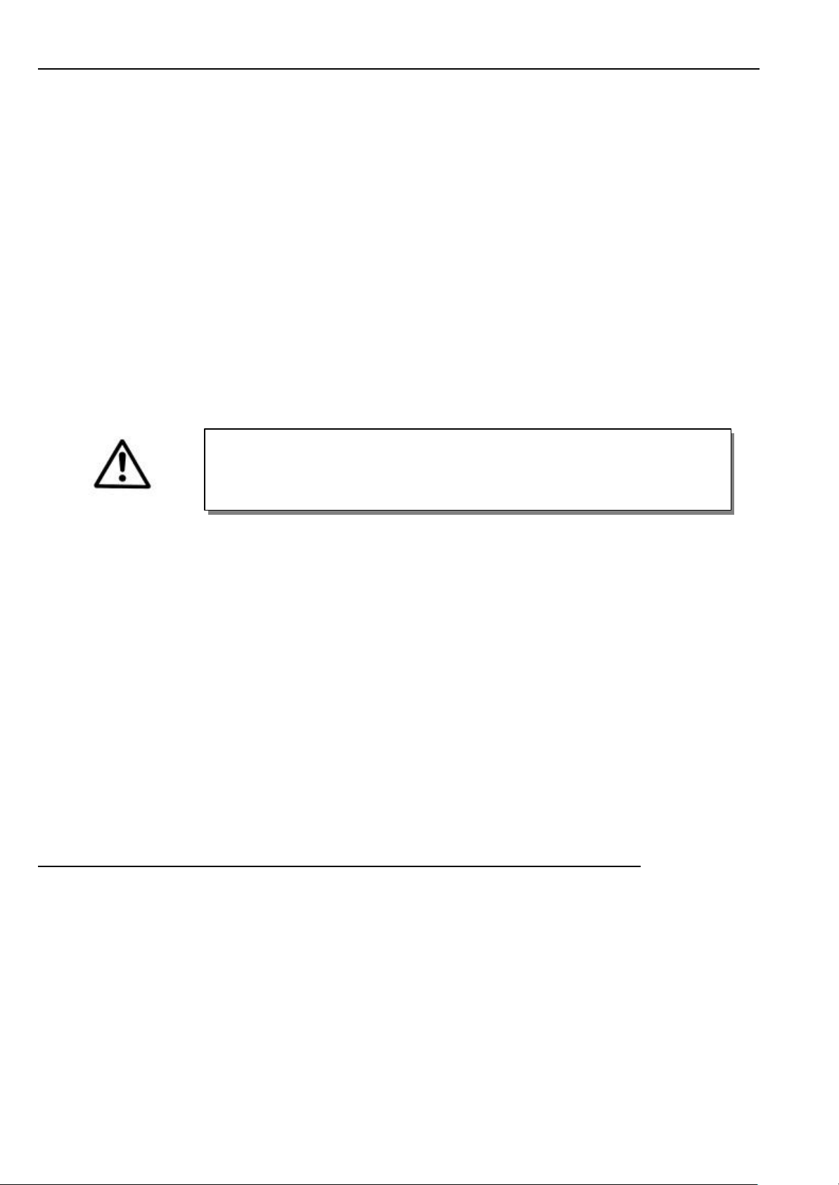
CAUTION
When selecting the installation site and the layout of the connecting cable, the Safety
Instructions in Section 1 must be followed with no exceptions.
Particular attention should be paid to maintaining the proper distance from moving parts!
3 Scope of Supply
1 Stepping motor control SM210A5710
1 Set of standard accessories B157
consisting of: Documentation
1 Set of accessories Z55
consisting of 37-pin SubminD plug
Potential equalization cord
3.1 Special Accessories
Stepping motor SM200 part no. 7900069
Stepping motor SM250 part no. 7900070
Connecting cable from the stepping motor control to the AB62CV d.c. drive part no. 1113113
Connecting cable from the stepping motor control to the AB220A d.c. drive part no. 1113172
Control panel Variocontrol V810 part no. 5970153
Control panel Variocontrol V820 part no. 5970154
4 Technical Data of the Stepping Motor Control
Motor driver voltage 35-45VDC
8 inputs 24VDC, active high/low
2 analog inputs 5VDC, Ri max. 1kΩ
5 outputs open collector, max. 60VDC, 0.5A, sum <2A
Mains voltage 230VAC, 50/60Hz
Stepping motors 2 phase s, with 4, 6, 8 connections, max. 3A/phase
Stepping motor control bipolar chopper, CW/CCW, half step
Weight 4.0 kg
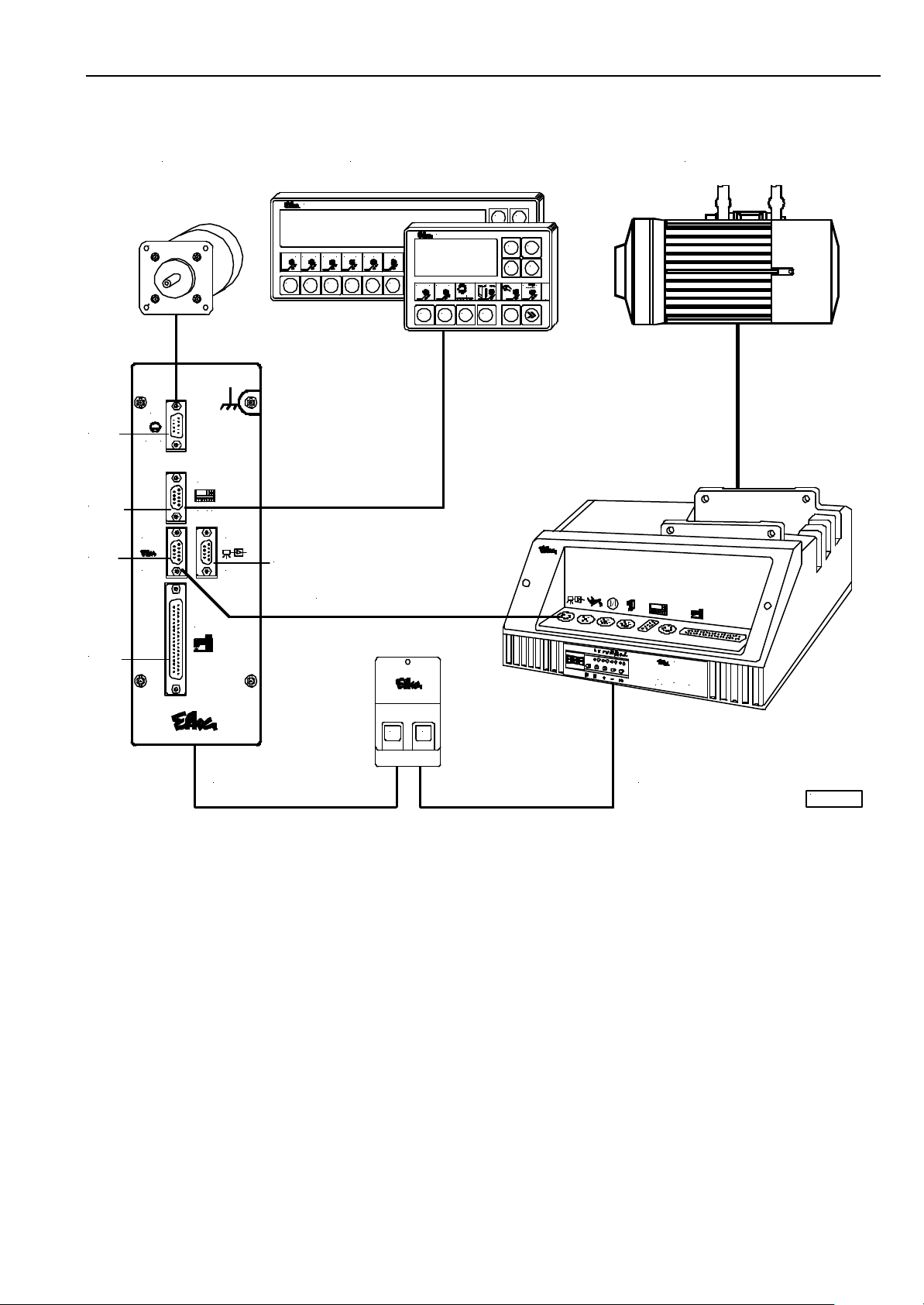
5 Connection Scheme for SM210A
mot
V810/V820
DC1600
EFKA SM210A57109
B5
B776
B18
M
motB51
B776
V8
. .
B18
control LSM...
B19
ST1
variocontrol 820
21 3
1 2 3 4 5 6
87654 11
B19
Nr. 1113113
9 10 12
1 2 3
1
variocontrol 810
4
2
P E
P
E
E
-
+
1
M
1
4
SM 01
43
M
ST1
0 I
SM210A.... AB62CV....
euramot
Steuerung Control Contrôle
Typ
AB62CV1466
KL2358
AB62CV.... control (B18) and SM210A....control (B18) are connected by adapter cord no. 1113113.
If a light barrier is required for the sewing process it must be connected to socket B9 on the stepping motor control. The light
barrier signal is transmitted via the connecting cable from the SM210A to the sewing drive.
5.1 Operating the Stepping Motor Control with a Sewing Control (e. g. AB62CV....)
Set parameter 162 of the sewing control with which communication is to be established, to “1”.
EFKA SM210A5710
10
M1L
M1L
M1L
M1L
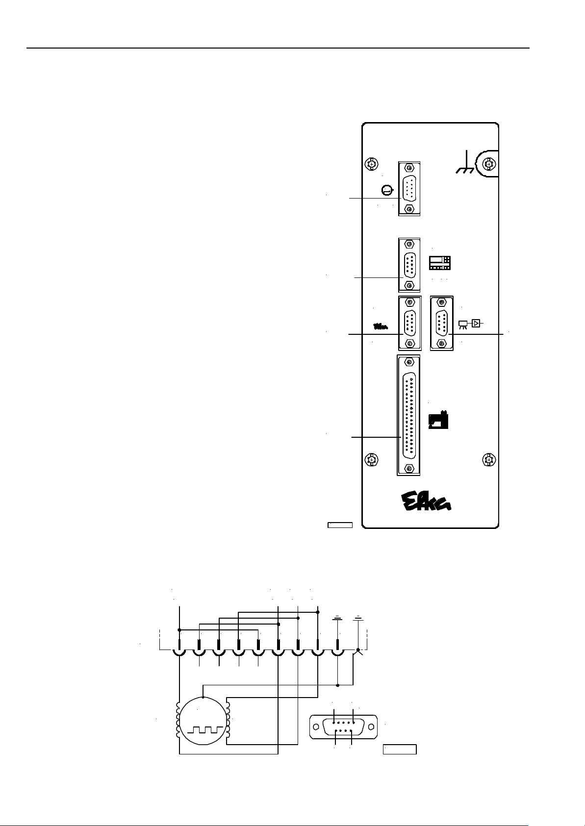
6 Socket Connectors
6.1 Position of the Socket Connectors
B5 Socket for stepping motor 1
B18 Socket for light barrier module or
transmission line
B19 Socket for light barrier module
B776 Socket for V810/V820 control panel
ST1 Socket for inputs and outputs of the solenoid
valves / displays / pushbuttons and switches
B5
B776
B18
ST1
mot1
B18
control
B5
M
B776
V8 . .
B19
B19
LSM...
ST1
6.2 Connection Diagram
B5
PH2
KL2355
2R
M
PH1
2L
54 6321
1L1R
987
51
SUB-D-9
(*)
96 KL2443
EFKA SM210A571011
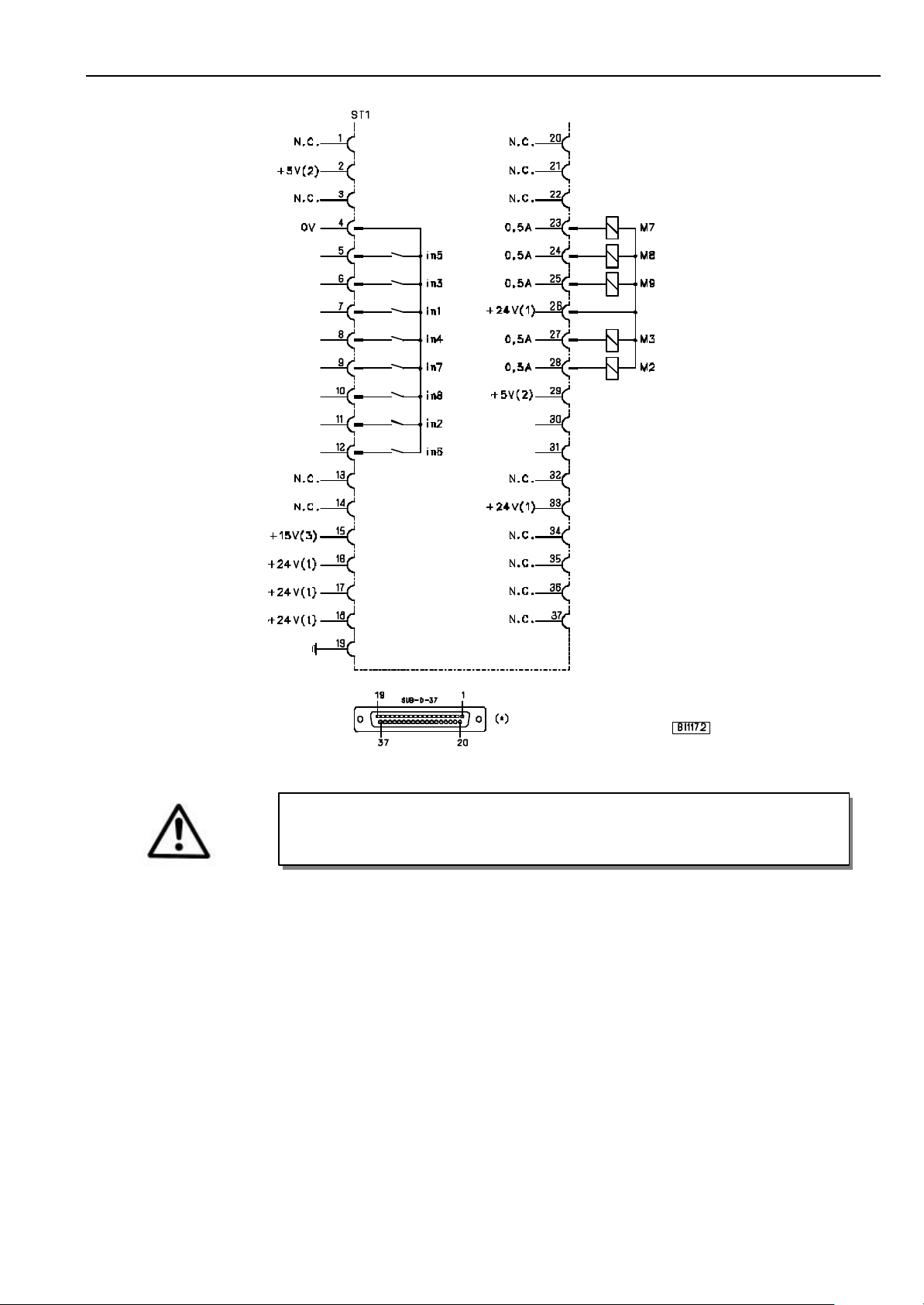
ATTENTION
When connecting the outputs, ensure that a total power of 48VA constant load will not
be exceeded !
in1 - Input 1 M2 - Output 2
in2 - Input 2 M3 - Output 3
in3 - Input 3 M7 - Output 7
in4 - Input 4 M8 - Output 8
in5 - Input 5 M9 - Output 9
in6 - Input 6
in7 - Input 7
in8 - Input 8
The input and output functions depend on the mode set with parameter 290.
1) Nominal voltage 24V, no-load voltage max. 30V momentarily after power On
2) Nominal voltage 5V, I
3) Nominal voltage 15V, I
*) Front view (component side) of the socket and/or rear view (soldering side) of the plug
= 20mA
max
= 30mA
max
EFKA SM210A5710
12
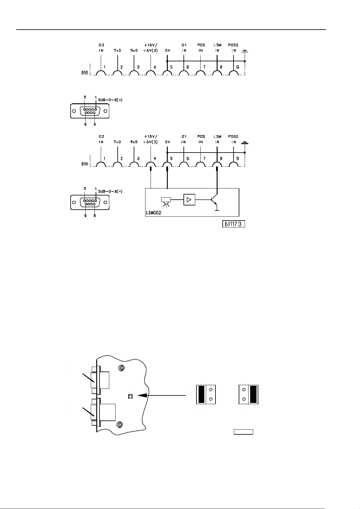
POS IN - Input for position
POS2 IN - Input for position 2
G1/G2 IN - Input for generator impulses
TXD/RXD - Serial transmission lines
LSM IN - Possibility of connecting a light barrier module to socket B18/8
(sensing of the signal upon switching to 0V)
LSM002 - Reflection light barrier module
For external devices there is a supply voltage of +5Von socket B19/4. After opening the cover, this voltage can be changed to
+15V by moving a multipole connector J3 to a different position on the printed circuit board.
+5V = Connect lefthand pins 1 and 2 with jumper (factory setting)
+15V = Connect righthand pins 3 and 4 with jumper
B776
B18
B19
J3
J3
1 3
2 4
J3
1
2
+15V+5V
3
4
KL2444
2) Nominal voltage 5V, I
= 20mA
max
*) Front view (component side) of the socket and/or rear view (soldering side) of the plug
EFKA SM210A571013
7 Stepping Motor Control Functions
7.1 Stepping Motor Function “Synchronous Operation“ (Pa. 290=0)
Functions Parameter
Metering device 290 = 0
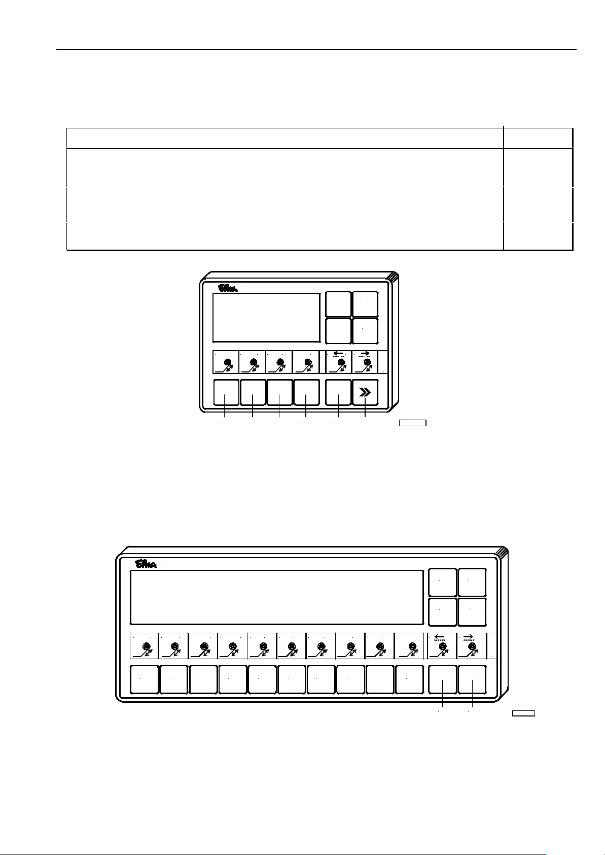
Insertable strip SM 05 for V810 control panel 291 = 5
Insertable strip SM 05 for V820 control panel 292 = 5
Connection of a pushbutton for tape cutter to socket ST1/7 (in1)
Connection of a pushbutton for selection of tape tension 8...1 and/or 18...1 to socket ST1/6 (in3)
Connection of a pushbutton for selection of tape tension 1...8 and/or 1...18 to socket ST1/8 (in4)
Connection of a pushbutton for metering device by means of a sensor on socket ST1/5 (in5)
Connection of a pushbutton for metering device on socket ST1/12 (in6)
variocontrol 810
P
E
-
+
1 2 3 4 5 6
1 32
4 A B
17 8 1 8
8
SM 05
KL2445
Pushbutton 1 = - Setting tape tension 1 or 2 (ratio stepping motor/d.c. drive)
Pushbutton 2 = - Setting tape tension 3 or 4 (ratio stepping motor/d.c. drive)
Pushbutton 3 = - Setting tape tension 5 or 6 (ratio stepping motor/d.c. drive)
Pushbutton 4 = - Setting tape tension 7 or 8 (ratio stepping motor/d.c. drive)
Pushbutton A = - Selection of tape tension 8...1 (parallel with input in3)
Pushbutton B = - Selection of tape tension 1...8 (parallel with input in4)
variocontrol 820
1 2 3
4 5 6 7 8 9 10 11 12 13
14
15 1716 18 1181
C
E
P
-
+
18
SM 05
1 2
3 4 5 6
7
98
0
B
A
Pushbutton 1...9 = - Setting tape tension 1...18 (ratio stepping motor/d.c. drive)
Pushbutton 0 = - Correction factor for switching between 2 tape tension values
Pushbutton A = - Selection of tape tension 18...1 (parallel with input in3)
Pushbutton B = - Selection of tape tension 1...18 (parallel with input in4)
KL2446
EFKA SM210A5710
14
Valid parameters if parameter 290 = 0 (synchronous stepping motor operation)
Parameter Functions max min Preset
002 c3 Number of stepping motor steps for metering device 9999 0 600
051 01- Value 1 of ratio on pushbutton 1 (V810/V820) 999 10 180
052 02- Value 2 of ratio on pushbutton 1 (V810/V820) 999 10 200
053 03- Value 3 of ratio on pushbutton 2 (V810/V820) 999 10 230
054 04- Value 4 of ratio on pushbutton 2 (V810/V820) 999 10 270
055 05- Value 5 of ratio on pushbutton 3 (V810/V820) 999 10 320
056 06- Value 6 of ratio on pushbutton 3 (V810/V820) 999 10 380
057 07- Value 7 of ratio on pushbutton 4 (V810/V820) 999 10 450
058 08- Value 8 of ratio on pushbutton 4 (V810/V820) 999 10 500
059 09- Value 9 of ratio on pushbutton 5 (V820) 999 10 550
060 10- Value 10 of ratio on pushbutton 5 (V820) 999 10 600
061 11- Value 11 of ratio on pushbutton 6 (V820) 999 10 650
062 12- Value 12 of ratio on pushbutton 6 (V820) 999 10 700
063 13- Value 13 of ratio on pushbutton 7 (V820) 999 10 750
064 14- Value 14 of ratio on pushbutton 7 (V820) 999 10 800
065 15- Value 15 of ratio on pushbutton 8 (V820) 999 10 850
066 16- Value 16 of ratio on pushbutton 8 (V820) 999 10 880
067 17- Value 17 of ratio on pushbutton 9 (V820) 999 10 900
068 18- Value 18 of ratio on pushbutton 9 (V820) 999 10 940
069 19- Value 19 of ratio on pushbutton 0 (V820) 999 10 960
070 --- Value 20 of ratio on pushbutton 0 (V820) 999 10 230
071 21- Value 21 of ratio on pushbutton 0 (V820) 999 0 208
112 n1 Fixed stepping motor speed with asynchronous operation [RPM] 600 0 100
113 n2 Fixed stepping motor speed with manual operation by means of pushb. A / B [RPM] 600 0 10
120 SnS From this sewing drive speed onwards signal M9 is emitted at the SM control 9990 0 0
130 rPd Select how to start metering device 7 1 1
131 bEE End of metering device at the start of the seam / seam end 2 0 0
132 Flo Lift sewing foot when feeding the tape On/Off 1 0 1
134 t7 Prolongation of blowing signal during metering device 9990 0 0
135 t5 Delay time until start of stepping motor for metering device [ms] 990 0 300
136 nFd Initiate end of stepping motor operation by thread trimming (see Parameter List) 1 0 1
137 nEd Initiate end of stepping motor operation by seam end (see Parameter List) 1 0 1
140 mbS Activate tape cutting by means of external pushbutton on input in1 / pedal –1 / 2 0 0
141 rbS Stepping motor runs parallel during tape cutting On/Off 1 0 0
142 t6 Activation time when operating the tape cutter manually at machine standstill [ms] 990 0 300
143 Ft2 Tape cutter until seam end or over time 1 0 0
152 SbS Function start tape tension. Last tape tension value or value selected by means 1 0 0
190 mbS Ratios are selected via inputs in3 and in4 1 0 0
220 d01 Percental adaptation of the stepping motor speed up to 500 RPM 200 0 100
221 d02 Percental adaptation of the stepping motor speed up to 1000 RPM 200 0 100
222 d03 Percental adaptation of the stepping motor speed up to 1500 RPM 200 0 100
223 d04 Percental adaptation of the stepping motor speed up to 2000 RPM 200 0 100
224 d05 Percental adaptation of the stepping motor speed up to 2500 RPM 200 0 100
225 d06 Percental adaptation of the stepping motor speed up to 3000 RPM 200 0 100
226 d07 Percental adaptation of the stepping motor speed up to 3500 RPM 200 0 100
227 d08 Percental adaptation of the stepping motor speed up to 4000 RPM 200 0 100
228 d09 Percental adaptation of the stepping motor speed up to 4500 RPM 200 0 100
229 d10 Percental adaptation of the stepping motor speed up to 5000 RPM 200 0 100
230 c7 Correction factor when switching to fast tape feeding 9999 0 25
231 c8 Correction factor when switching to slow tape feeding 9999 0 90
291 810 Selection of insertable strip for V810 5 1 5
292 820 Selection of insertable strip for V820 5 1 5
293 tF1 Function of pushbutton A on the V810/V820 control panels 10 0 0
294 tF2 Function of pushbutton B on the V810/V820 control panels 10 0 0
pedal -2
of pushbutton 1
See chapter “Parameter List” for values of the general parameters as well as for more detailed explanations of the above
parameters.
DC drive parameters:
Sign Function Parameter
n1 Positioning speed 110
n2 Maximum speed 111
n7 Trimming speed 116
t3 Start delay from lifted foot 202

7.1.1 Timing Diagram “Synchronous Stepping Motor Operation“ (Pa. 290=0)
1
-
1/2
0
+
-1
-2
EFKA SM210A571015
MODE-0a
POS.1
ST2/20
DC
POS.2
ST2/21
FL
ST2/35
SM
SM
in1
ST1/7
in2
ST1/11
SM
in6
ST1/12
M2
ST1/28
M3
ST1/27
M7
ST1/23
M8 (BM)
ST1/24
M9
ST1/25
n
t3 tx
n2 n1 n2 n7
9
(FF)
(BL)
(SML)
(DR)
SM SM
10
MODE-0b
Abbreviations for d.c. drive:
POS1 = Position 1 on the sewing machine
POS2 = Position 2 on the sewing machine
FL = Sewing foot lift
Abbreviations for stepping motor:
SM>> = Direction of rotation of stepping motor: cw (speed synchronous with d.c. drive)
SM<< = Direction of rotation of stepping motor: ccw (speed synchronous with d.c. drive)
in1 = Pushbutton for tape cutter
in2 = Pushbutton for metering device
M3 (BL) = Signal “blowing”
M7 (SML) = Signal “stepping motor running”
M8 (BM) = Tape cutter
M9 (DR) = Signal “direction of rotation”
*9 Synchronous operation according to d.c. drive speed. The transmission ratios are selected by means of pushbuttons 1...4
on V810 and pushbuttons 1...9 on V820.
*10 Signal “direction of rotation remains On until the direction of rotation is reversed.
 Loading...