

Page 1
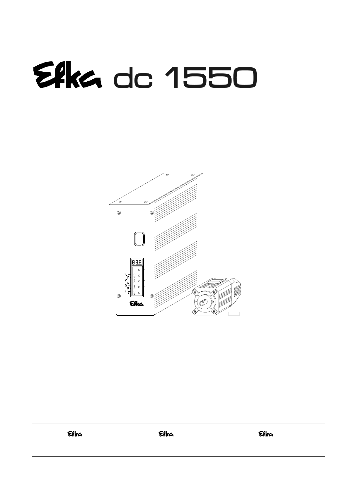
CONTROL AB320A5200
0
I
P
E
+
-
>>
KL2334a
LIST OF PARAMETERS
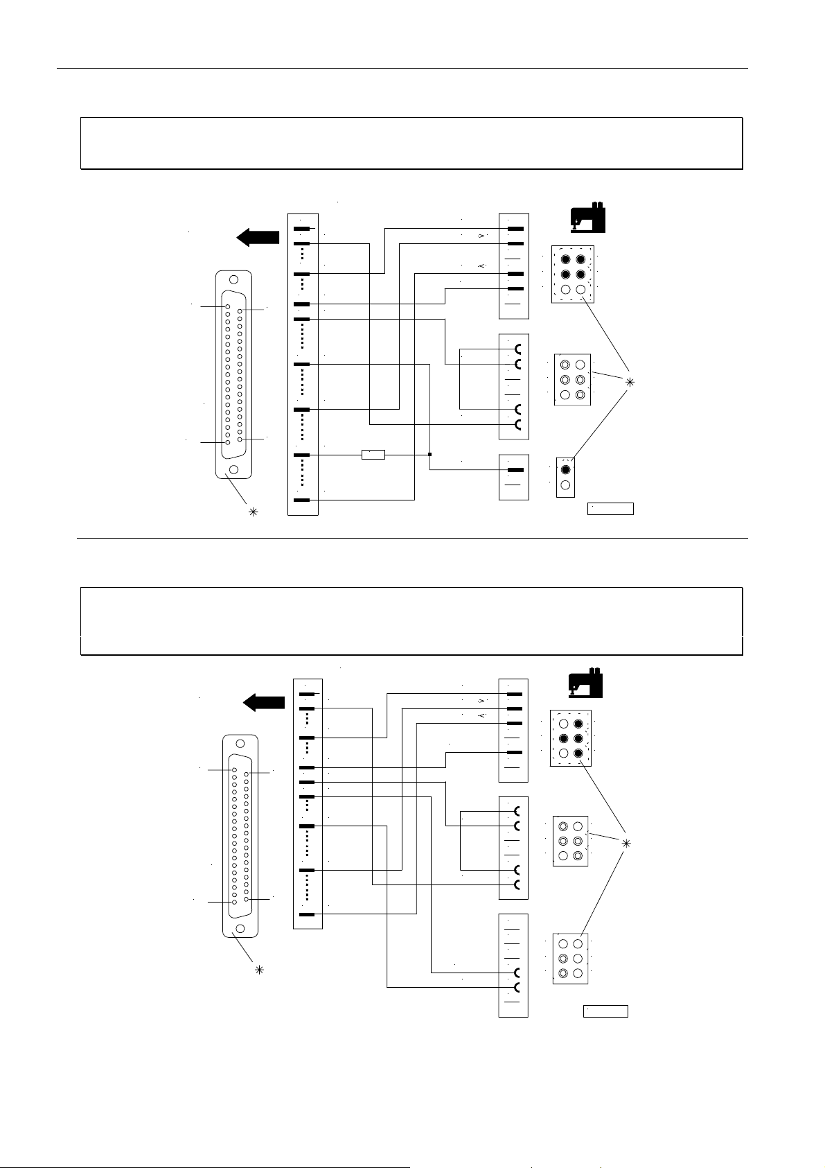
CONNECTION DIAGRAM
TIMING DIAGRAMS
No. 402286 English
FRANKL & KIRCHNER EFKA OF AMERICA INC. EFKA ELECTRONIC MOTORS
GMBH & CO KG SINGAPORE PTE. LTD.
Page 2

3
EFKA AB320A5200
CONTENTS Page
1 Table of Adapter Cords 5
2 Putting into Service 6
3 Setting and Putting into Service with the Aid of the Fast Installation Routine (SIR) 7
4 Operating Elements and Socket Connectors 8
4.1 Position of Operating Elements and Displays 8
4.2 Position of the Socket Connectors 9
4.3 Connection Diagram 10
4.4 Connection of a Sewing Light with Transformer 13
4.5 Adapter Cords 14
5 Timing Diagrams 29
6 List of Parameters 56
6.1 Preset Values Depending on Mode 56
6.2 Operator Level 58
6.3 Technician Level 60
6.4 Supplier Level 65
7 Error Displays 78
8 Slide-in Strips for the V810/V820 Control Panels 79
Page 3
1 Table of Adapter Cords
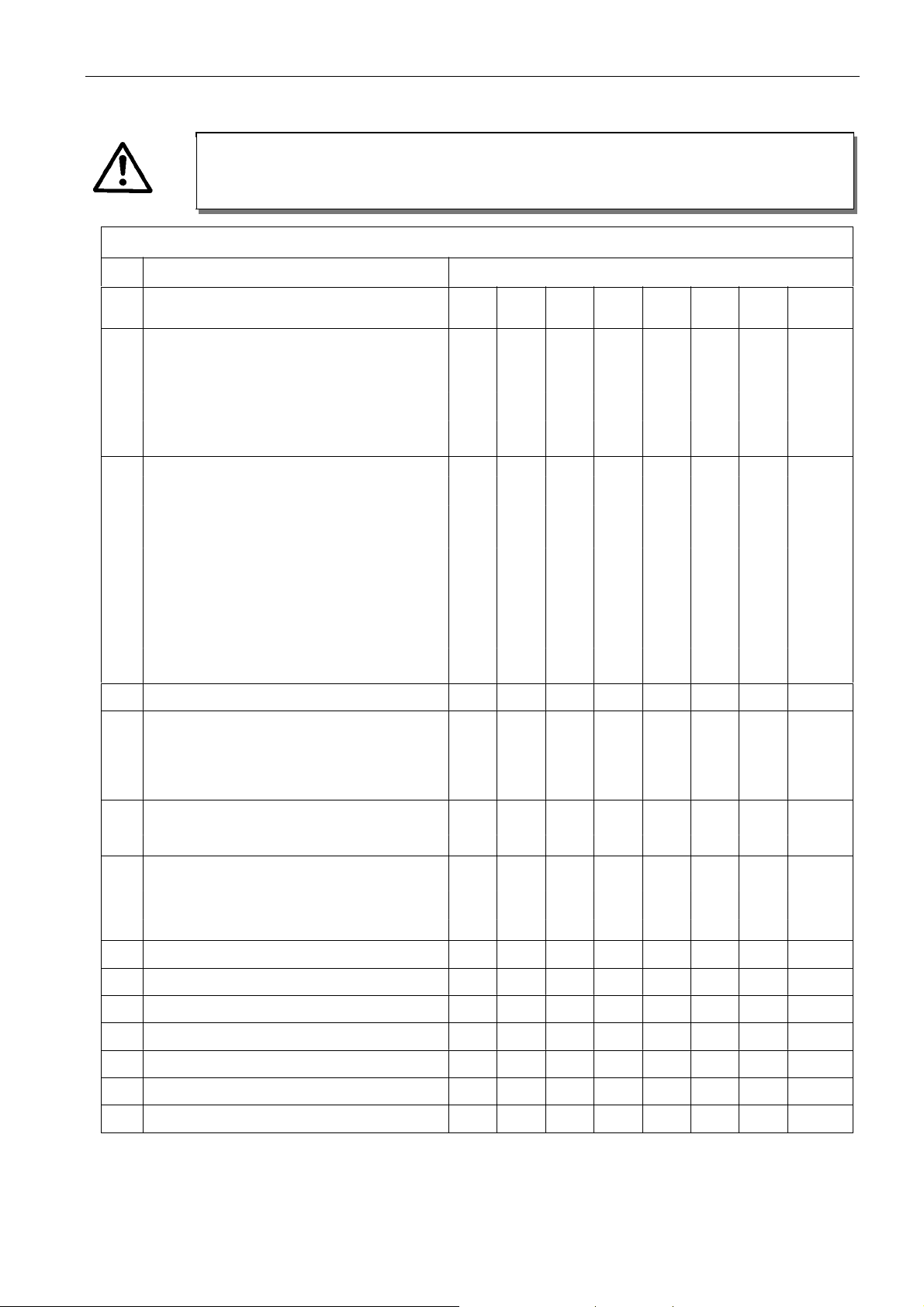
Before switching functional sequences, detach cables from the inputs and outputs! Please ensure that the
machine installed provides the functional sequence to be set! Then proceed with the setting using parameter
Setting the functional sequence using parameter 29 0
Mode Designation Adapter Outputs
5
ATTENTION!
290!
EFKA AB320A5200
Power transistors !!!! FL VR M1 M2 M3 M4 M5 M6
0 Lockstitch; e. g. Functions FL VR FA1 FA2 FW FA1+2 ML MST
Brother (737-113, 737 -913) 1112814 FL VR FA1 + FA2 FW
Aisin (AD3XX, AD158, 3310; EK1) 1112815 FL VR FA1 + FA2 FW
Pfaff (563, 953, 1050, 1180) 1112841 FL VR FA1 FA2 FW ML
Dürkopp Adler (210, 270) 1112845 FL VR FA1 + FA2 FW
2 Lockstitch; e. g. Functions FL VR FA FSPL FL1 ML MST
Singer (212 UTT) 1112824 FL VR FA FSPL FL1
3Lockstitch; e. g. Dürkopp Adler (467) FL VR FA FSPL FW ML MST
4 Chainstitch; e. g. Union Special Functions FL FA-R M1 FA-V FW STV ML
(34000 and 36200 replacement for US80A) 1112865 FL FA-R FA-V FW ML
(CS100 and FS100) 1112905 FL FA-R M1 FA-V FW ML
5 Chainstitch; parallel sequence Functions FL STV M1 M2 M3 M4 ML MST
Bag sewing machine Union Special Functions FL IMP BR ML MST
Yamato (VC series) 1112818 FL STV FA FW
Yamato (VG series) 1113178 FL STV FA FW ML
Kansai (RX 9803) 1113130 FL FA FW ML
Pegasus (W500/UT, W600/UT/MS 1112821 FL STV FA FA FW
with or without st itch condensing)
Brother (FD3-B257) 1112822 FL STV FA FA FW
Union Special (34700) 1112844 FL STV FA FA FW NK
Global (CB2803-56) 1112866 FL FA
Rimoldi (F27) 1113096 FL FW FAO FAU ML
6 Chainstitch; tape cutter/fast scissors FL STV M1 M2 AH1 AH2 ML MST
7 Overlock FL KS M1 M2 AH FSPL ML MST
8 Backlatch Functions FL PD≤≤≤≤-1 PD≥≥≥≥1PD≥≥≥≥1* ML MST
Pegasus 1113234 PD≤-1 PD≥1
9 Backlatch Functions FL PD≤≤≤≤-1 PD≥≥≥≥1PD≥≥≥≥1* ML MST
Yamato (ABT3) 1112826 PD≤-1 PD≥1
Yamato (ABT13, ABT17) 1113205 PD≤-1 PD≥1
ST2/35 ST2/34 ST2/37 ST2/28 ST2/27 ST2/36 ST2/32 ST2/30
10 Lockstitch; e. g. Functions FL FA-R FSPL FA-V FW VR ML MST
Union Special (63900AMZ replacement 1112823 FL FA-R FA-V FW ML
for US80A) and on Refrey lockstitch machines
14 Lockstitch; e. g. Functions FL VR FA1+2 FA2 FW FA1 ML MST
Juki (5550-6) 1112816 FL VR FA1+2 FW
Juki (5550-7) 1113132 + FL VR FA1+2 FZ FW
(position sens or incorporated in the 1113157
handwheel)
15 Backlatch Pegasus (SSC100) FL KS/KB KB KS FSPL AH ML HP
16 Overlock; feed-off-the-arm machine e.g.Yamato (FD62) FL KS RB M2 AH FSPL ML MST
17 Chainstitch; Pegasus FL LFA FA STS ML
20 Lockstitch; Juki (LU1510-7) 1113200 FL VR FA FSPL ML MST
21 Chainstitch; Yamato (stitch lock) 1113178 FL STS FA STV FW ML
23 Lockstitch; Dürkopp Adler (271...275) FL VR FA ML FW FSPL HP MST
24 Chainstitch; Pegasus (MHG-100) 1113267 FL FA FA FW
*) The signal issued at this output is inverted!
Page 4

EFKA AB320A5200
Explanation of letter symbols of the previous page and chapter ”Timing Diagrams“
Outputs:
FL = Sewing foot lifting FL1 = Sewing foot lifting without pulsing
VR = Backtacking STV = Stitch condensing
FA = Thread trimmer FA1 = Thread trimmer pos. 1...1A
FA2 = Thread trimmer pos. 1A...2 FA1+2 = Thread trimmer pos. 1...2
FA-V = Thread trimmer forward FA-R = Thread trimmer backward
FAU = Bobbin thread trimmer FAO = Needle thread trimmer
FSPL = Thread tension release AH = Tape cutter
FW = Thread wiper AH1/AH2 = Fast scisso rs
ML/NK = Machine running / Needle cooling KS = Chain suction
RB = Chain blowing in opposite direction STB = Blow fabric onto stack
KB = Chain blowing KS+KB = Chain suction + bl owing
MST = Machine at standstill HP/FF1 = High lift for walking foot /
PD≥1 = Pedal steps 1...12 flip-flop 1
PD=0 = Pedal step 0 PD≤-1 = Pedal steps –1 / -2
L-STL = Indicator lamp for stitch length PD-2 = Pedal step -2
FZ = Thread puller DR-UK = Reversal of motor direction
IMP = Impulse STS = Stitch lock
LFA = Top cover thread cutter BR = Hot thread chain cutting
6
2 Putting into Service
Before putting the control into service, the following must be ensured, checked and/or adjusted:
" The correct installation of the drive, position transmitter and accompanying devices, if necessary
"
The correct selection of the trimming operation by means of parameter 290
" If necessary, the correct adjustment of the direction of motor rotation by means of parameter 161
" The correct selection of the functions of keys (inputs) by means of parameters 240...249
" The setting of the transmission ratio between motor shaft and machine shaft by means of parameter 272
" The setting of the type of position sensor by means of parameter 270
"
If necessary, the setting of the number of angular degrees after the sensor position by means of parameter 271
" If necessary, the setting of the positions by means of parameter 171
(possible with all settings of parameter 270)
" The correct positioning speed by means of parameter 110
"
The correct maximum speed compatible with the sewing machine by means of parameter 111
" The setting of the remaining relevant parameters
"
Start sewing in order to save the set values
See instruction manual for details!
Page 5
7
EFKA AB320A5200
3 Setting and Putting into Service with the Aid of the Fast Installation
Routine (SIR)
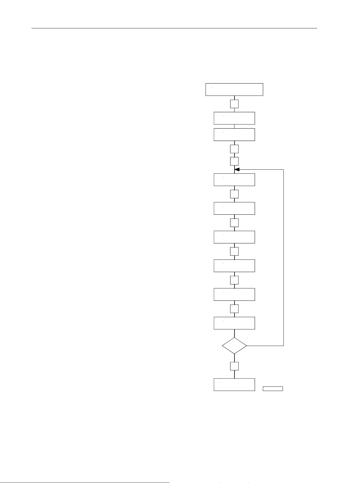
The Fast Installation Routine (SIR) passes through all parameters necessary for programming the functional sequence and
the positions.
Code 3112
E
F-200
Input parameter 500
Parameter for functional sequence “thread trimming operations”
Parameter for direction of motor rotation
Parameter for transmission ratio
Important! The transmission ratio should be
determined and indicated as prec is ely as possible.
Parameter for type of position sensor
Parameter for position 1
F-500
E
>>
F-290
E
F-161
E
F-272
E
F-270
E
F-451
E
Parameter for position 2
F-453
Yes
E
No
P
End SIR
The values can be varied by pressing the +/- keys. When the parameter is displayed on the V810 control panel, press
the E key once more for the value to be displayed.
Exit the routine any time by pressing the P key once, and select a new parameter. Exit programming by pressing the P key
twice, and the drive is ready for a new sewing operation.
See instruction manual for details!
KL2438a
Page 6
EFKA AB320A5200
8
4 Operating Elements and Socket Connectors
4.1 Position of Operating Elements and Displays
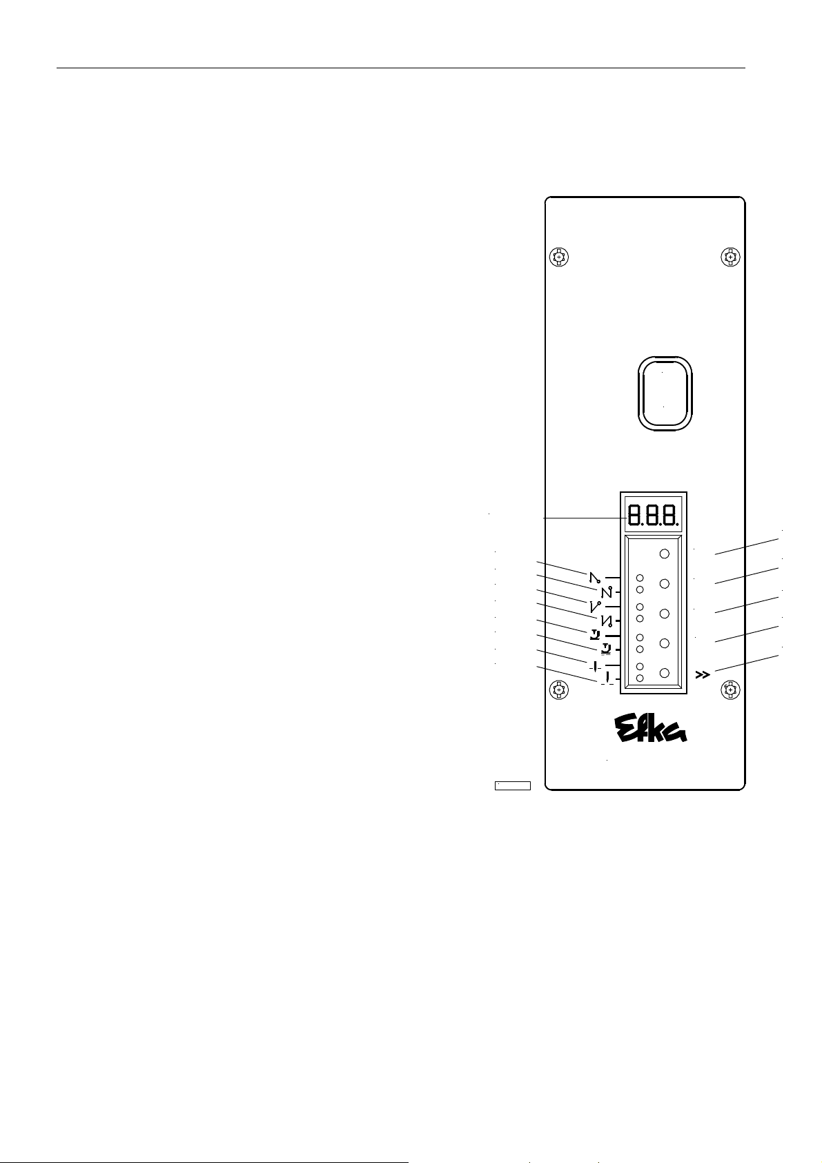
S1 P key
" Call or exit programming mode
S2 E key
"
Start backtack single / double / off
" Enter key for modifications in the programming mode
S3 + key
" End backtack single / double / off
" Increase of the value indicated in the programming mode
S4 – key
"
Automatic sewing foot lifting at stop in the seam On/Off
" Automatic sewing foot lifting after thread trimming
On/Off
" Decrease of the value indicated in the programming mode
S5 >> key
" Basic position 1 or 2
"
Shift key in the programming mode
0
I
LED1 Indicator for single start backtack
LED2 Indicator for double start backtack
LED3 Indicator for single end backtack
LED4 Indicator for double end backtack
LED5 Indicator for automatic sewing foot lift at stop
in the seam
LED6 Indicator for automatic sewing foot lift after
the thread trimming operation
LED7 Indicator for basic position “needle position 1“
LED8 Indicator for basic position “needle position 2“
Display 3 digits
Display
LED1
LED2
LED3
LED4
LED5
LED6
LED7
LED8
KL2472
AB320A5200
S1
P
E
+
-
S2
S3
S4
S5
Page 7
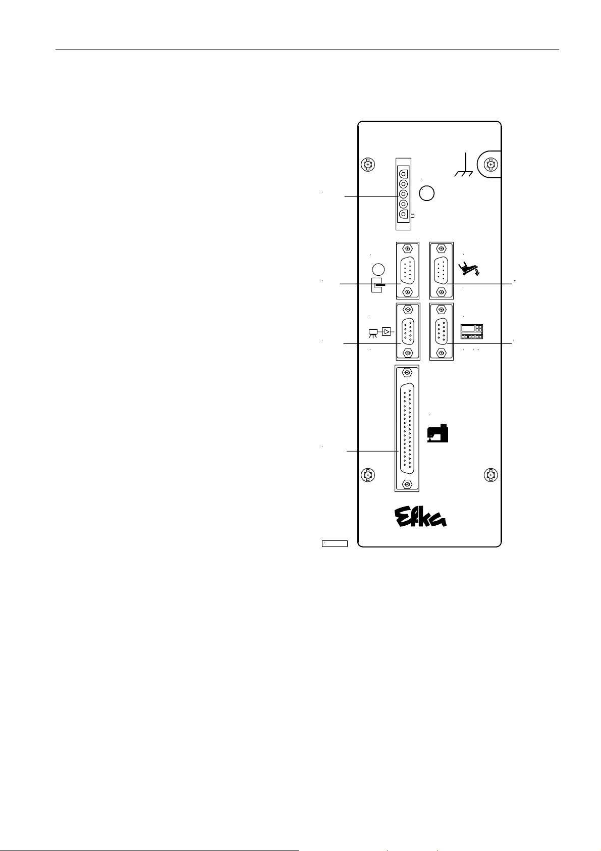
4.2 Position of the Socket Connectors
B2 Socket for sensors
9
EFKA AB320A5200
B18 Socket for light barrier module
B41 Socket for motor power supply
B80 Socket for actuator
B776 Socket for V810/V820 control panel
ST2 Socket for solenoid inputs and outputs /
solenoid valves / displays / keys and switches
B41
B2
B18
ST2
B2
M
B18
L S M ...
B41
M
ST2
B80
EB ...
B 776
V8 . .
B80
B776
KL2333
Page 8

EFKA AB320A5200
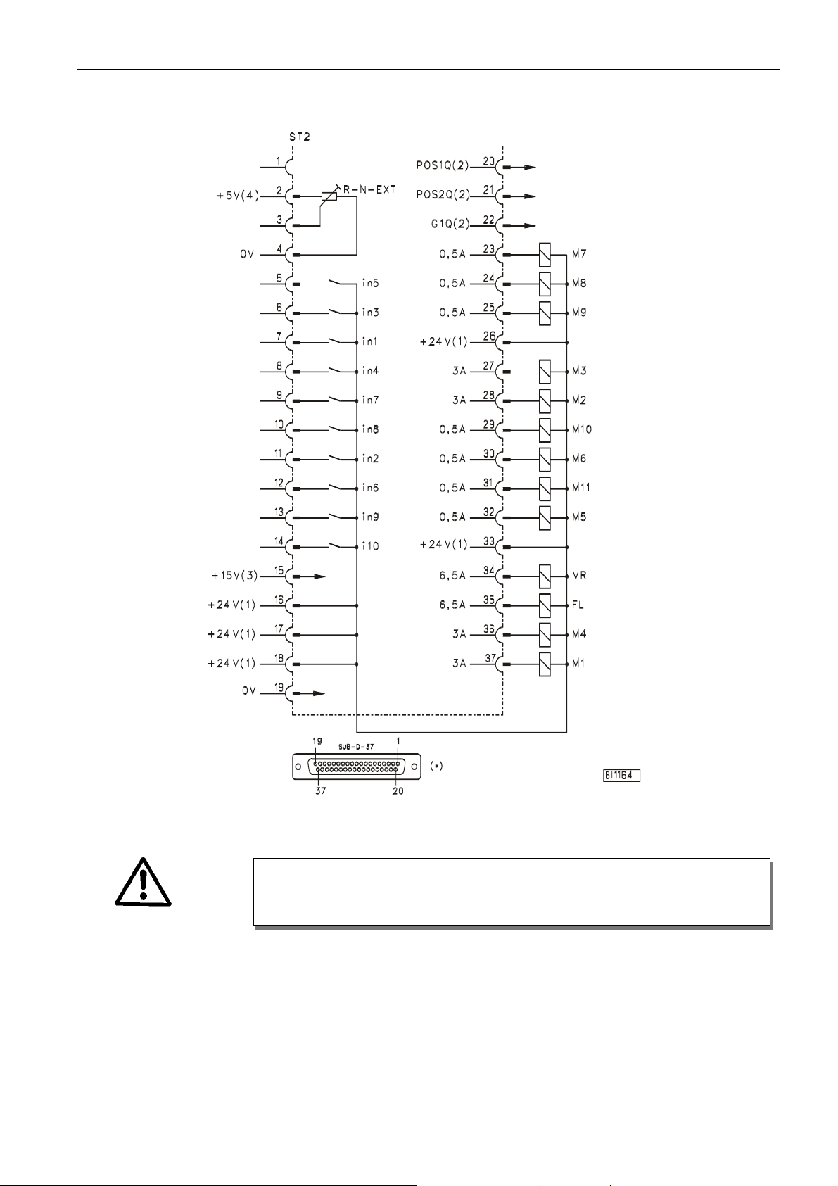
4.3 Connection Diagram
Inputs switched to 0V
10
ATTENTION!
When connecting the outputs, ensure that a total power of 96VA constant load will not
be exceeded!
in1 - Input 1 i10 - Input 10 M9 - Output 9
in2 - Input 2 M1 - Output 1 M10 - Output 10
in3 - Input 3 M2 - Output 2 M11 - Output 11
in4 - Input 4 M3 - Output 3 FL - Sewing foot lifting
in5 - Input 5 M4 - Output 4 VR - Backtacking
in6 - Input 6 M5 - Output 5 POS1 - Position 1
in7 - Input 7 M6 - Output 6 POS2 - Position 2
in8 - Input 8 M7 - Output 7 GEN - 512 generator impulses
in9 - Input 9 M8 - Output 8 R-N-EXT - External potentiometer for
speed limitation (50kΩ)
Page 9
Inputs switched to +24V
11
EFKA AB320A5200
ATTENTION!
When connecting the outputs, ensure that a total power of 96VA constant load will not
be exceeded!
1)
Nominal vol t age 24V, no-load voltage max. 30V momentarily after power on
2)
Transistor output with open collector max. 40V, 10mA
3) Nominal voltage 15V, I
4)
Nominal voltage 5V, I
= 30mA
max
= 20mA
max
*) Front view of the socket (component side) and/or rear view of the plug (soldering side)
Page 10

EFKA AB320A5200
POS2 OUT - Output for position 2
POS IN - Input for positions
G1/G2 OUT - Output of generator impulses
TXD/RXD - Serial transmission lines
LSM IN - Possibility of connecting a light barrier module to socket B18/8
LSM002 - Reflection light barrier module
12
(If parameter 239 = 0, the light barrier function is selected.
Identification of the signal when switched to 0V.)
If parameter 239 is set to 1...43, a key can be operated on the input of socket B18/8.
+5V = Connect lefthand pins 1 and 2 with jumper (factory setting)
+15V = Connect righthand pins 3 and 4 with jumper
B80
B2
B18
J4
ATTENTION!
efore opening the cover, turn power off!
B
J4
1 3
2 4
+5V
J4
31
42
+15V
KL2351
1) Nominal voltage +15V, 100mA (repluggable to +5V, 100mA)
2) Transistor output with open collector max. 40V, 10mA
*) Front view of the socket (component side) and/or rear view of the plug (soldering side)
Page 11
13
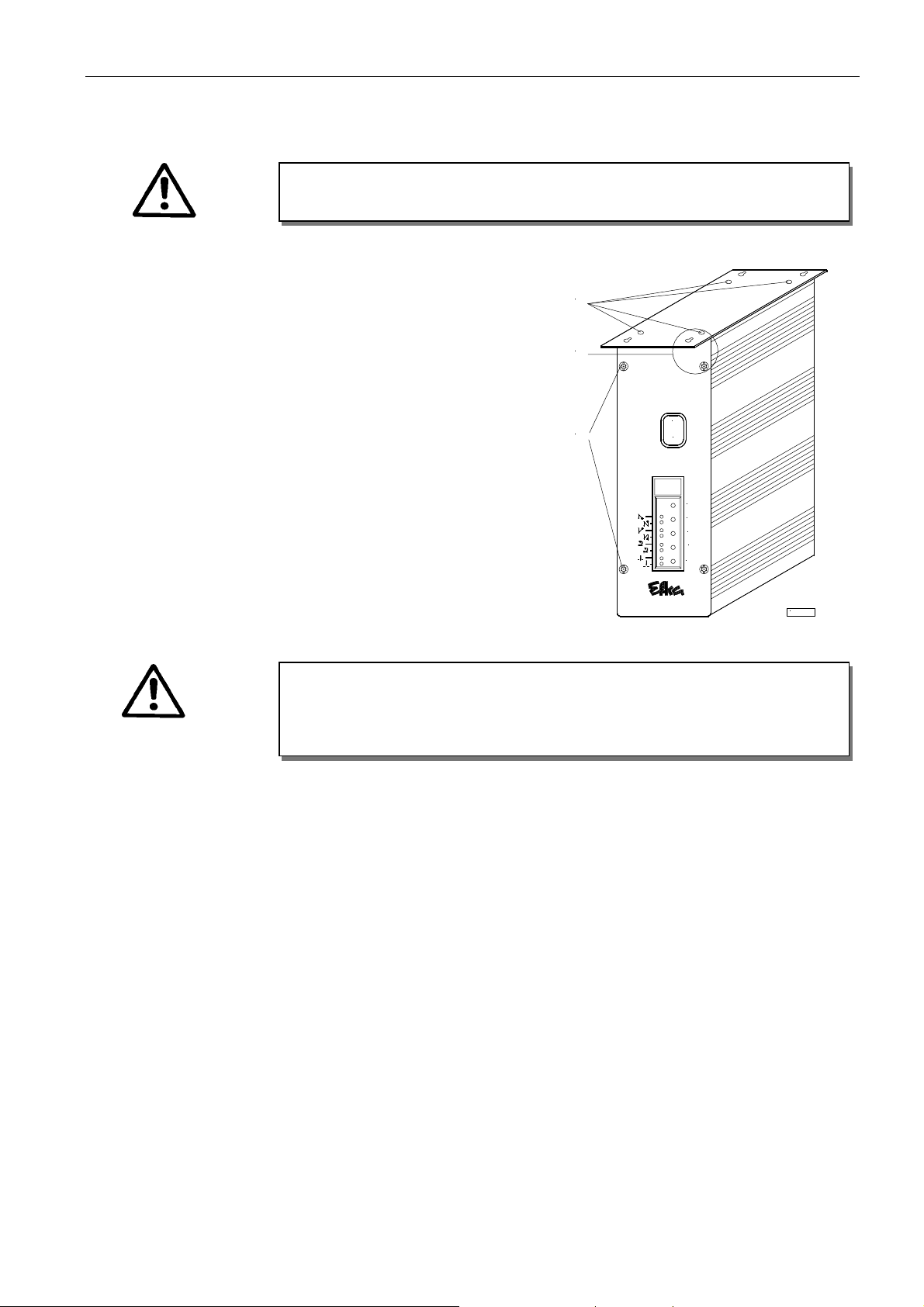
4.4 Connection of a Sewing Light with Transformer
ATTENTION!
efore opening the cover, turn power off!
B
EFKA AB320A5200
" Switch off the control and remove mains plug from outlet
"
Unscrew the control unit from the machine table
" Loosen 4 screws (A)
"
Remove the mounting plate
" Loosen 2 screws (B) each at the front and at the rear
" Open the left part of the housing
" Pull the sewing light cable through the cable bushing
"
Area (C): Connect strands with clamp on the printed circuit board
" Insert earth lead into plug-in device on the housin g part
"
Close and screw-connect the housing
" Mount the control unit on the machine table
When the sewing light is connected, it is always current-carrying (230V), even if
the control unit is switched off! Only one sewing light with transformer can be
connected to the control unit!
A
C
B
CAUTION!
0
I
P
E
+
-
>>
KL2399
Page 12
EFKA AB320A5200
14
4.5 Adapter Cords
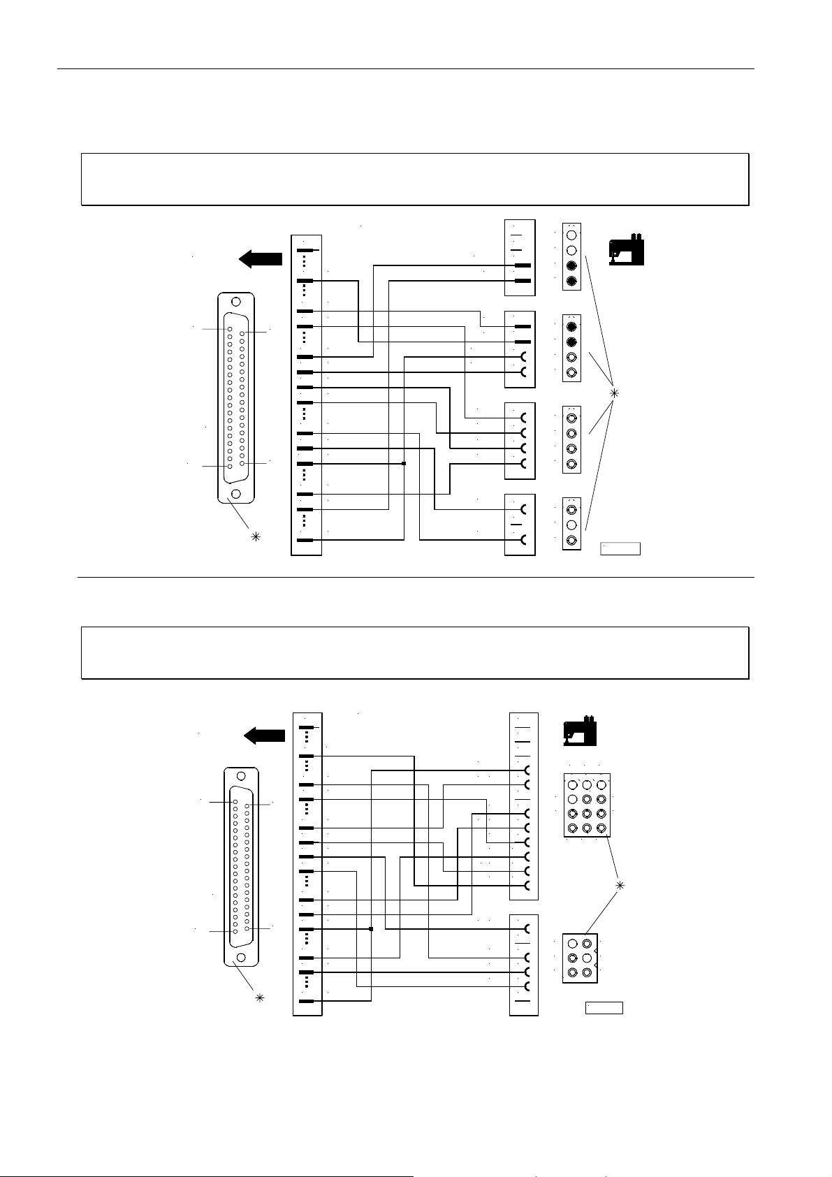
Adapter cord for AISIN models AD3XX, AD158, 3310 and EK1
Setting the functional sequence Thread trimming mode ! Set parameter 290 = 0
Setting the functions of the keys Input in1 ! Set parameter 240 = 16
Input in3 ! Set parameter 242 = 1
1
ST2
Nr. 1112815
0V
4
6 in3
1
SUB - D- 37
19
20
37
7 in1
+24V
16
+24V
17
+24V
18
19 0V
+24V26
27 M3
28 M2
VR
3534FL
37
M1
Adapter cord for BROTHER models 737-113 and 737-913
+24V
FL
NHT
0V
FA1+ 2
+24V
ZVR
0V
+24V
VR
FW
+24V
1
1
2
2
3
3
4
4
1
1
2
2
3
3
4
4
1
1
2
2
3
3
4
4
1
1
2
2
3
3
KL2234
Setting the functional sequence Thread trimming mode ! Set parameter 290 = 0
Setting the functions of the keys Input in1 ! Set parameter 240 = 16
Input in3 ! Set parameter 242 = 1
Nr . 11 12 8 14
0V
+24V
+24V
+24V
+24V26
FA1+ 2
24V
+
FW
24V
ZVR
VR
24V++
0V 12
24V
+
NHT
FL
0V
10
11
1
2
3
4
5
6
7
8
9
1
2
3
4
5
6
3
2 1
5
6
9
12
6
5
4
8
11 10
KL2233
4
7
3
2
1
ST2
1
19
SUB - D - 37
20
37
1
4
6 in3
7 in1
16
17
18
19 0V
27 M3
28 M2
34
35VRFL
37 M1
*) Rear view (soldering side) of 37-pin plug (ST2). Front view (component side) of the remaining plugs/sockets.
Page 13
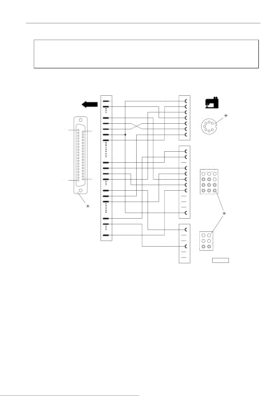
15
EFKA AB320A5200
Adapter cord for BROTHER model FD3 B257
Setting the functional sequence Thread trimming mode ! Set parameter 290 = 5
Setting the functions of the keys Input in1 ! Set parameter 240 = 7
Input in3 ! Set parameter 242 = 18
Input in4 ! Set parameter 243 = 16
Input in5 ! Set parameter 244 = 17
ST2
1
19
SUB - D - 37
20
37
1
+5V
2
4
0V
in55
in36
in17
in4
8
+ 24V
16
+ 24V
17
+ 24V
18
19 0V
+ 24V
26
27
M3
28 M2
34
VR
35 FL
37
M1
Nr. 1112822
LSP
ZSTV
0V
+5V
EN TK
STVU
FW
+ 24V
STV
+ 24V
FA
0V
+ 24V
FA
LSP
+ 24V
FL
10
11
12
1
2
3
4
5
6
7
1
2
3
4
5
6
7
8
9
1
2
3
4
5
6
1
3
12
3
2 1
6
7
5
8
1011
3
2
1
KL2241
4
7
4
2
5
6
9
6
5
4
*) Rear view (soldering side) of 37-pin plug (ST2). Front view (component side) of the remaining plugs/sockets.
Page 14
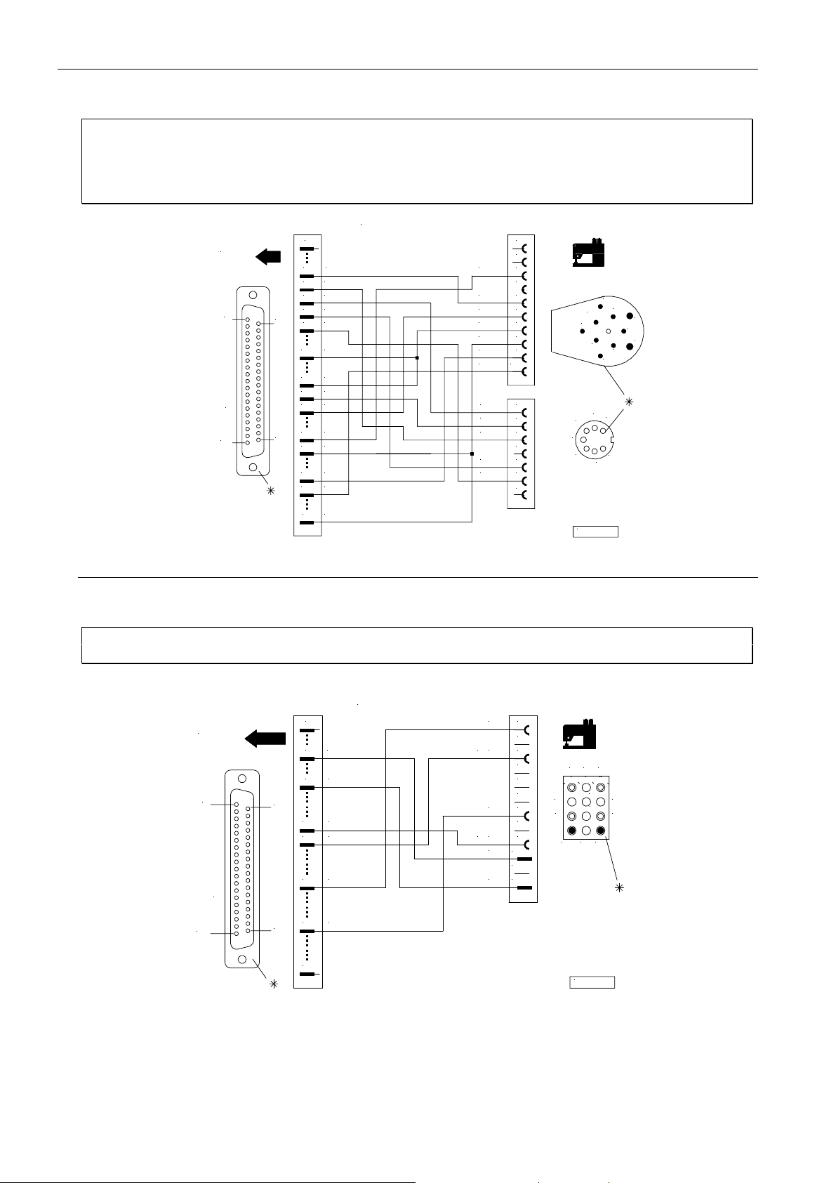
EFKA AB320A5200
16
Adapter cord for DÜRKOPP ADLER models 210, 270
Setting the functional sequence Thread trimming mode ! Set parameter 290 = 0
Setting the functions of the keys Input in1 ! Set parameter 240 = 16
Input in3 ! Set parameter 242 = 1
Input in4 ! Set parameter 243 = 3
Input in5 ! Set parameter 244 = 17
Nr. 1112845
0V
in5
in3
in4
+ 24V
+ 24V
M2
FW
0V
POS1
+24V 7
FA1+ 2
VR
FL
NHT
0V
VRU
ZVR
EST
10
1
2
3
4
5
6
8
9
1
2
3
4
5
6
7
1
4
2
5
KL2259a
10
9
8
7
6
2
1
3
5
4
3
6
7
ST2
1
SUB - D- 37
19
20
37
1
4
5
6
78in1
16
18
19 0V
20 POS1
27 M3
28
34 VR
35 FL
37 M1
Adapter cord for GLOBAL model CB2803-56
Setting the functional sequence Thread trimming mode ! Set parameter 290 = 5
Setting the functions of the keys Input in1 ! Set parameter 240 = 6
1
ST2
0V
4
7 in1
1
SUB - D- 37
19
*) Rear view (soldering side) of 37-pin plug (ST2). Front view (component side) of the remaining plugs/sockets.
20
37
+ 24V
17
+ 24V
18
27 M3
35 FL
37
FA
24V
+
FL
24V
0V
LSP+12
10
11
1
2
3
4
5
6
7
8
9
6
9
3
12
2 1
5
8
11
10
KL2301
4
7
Nr. 1112866
Page 15
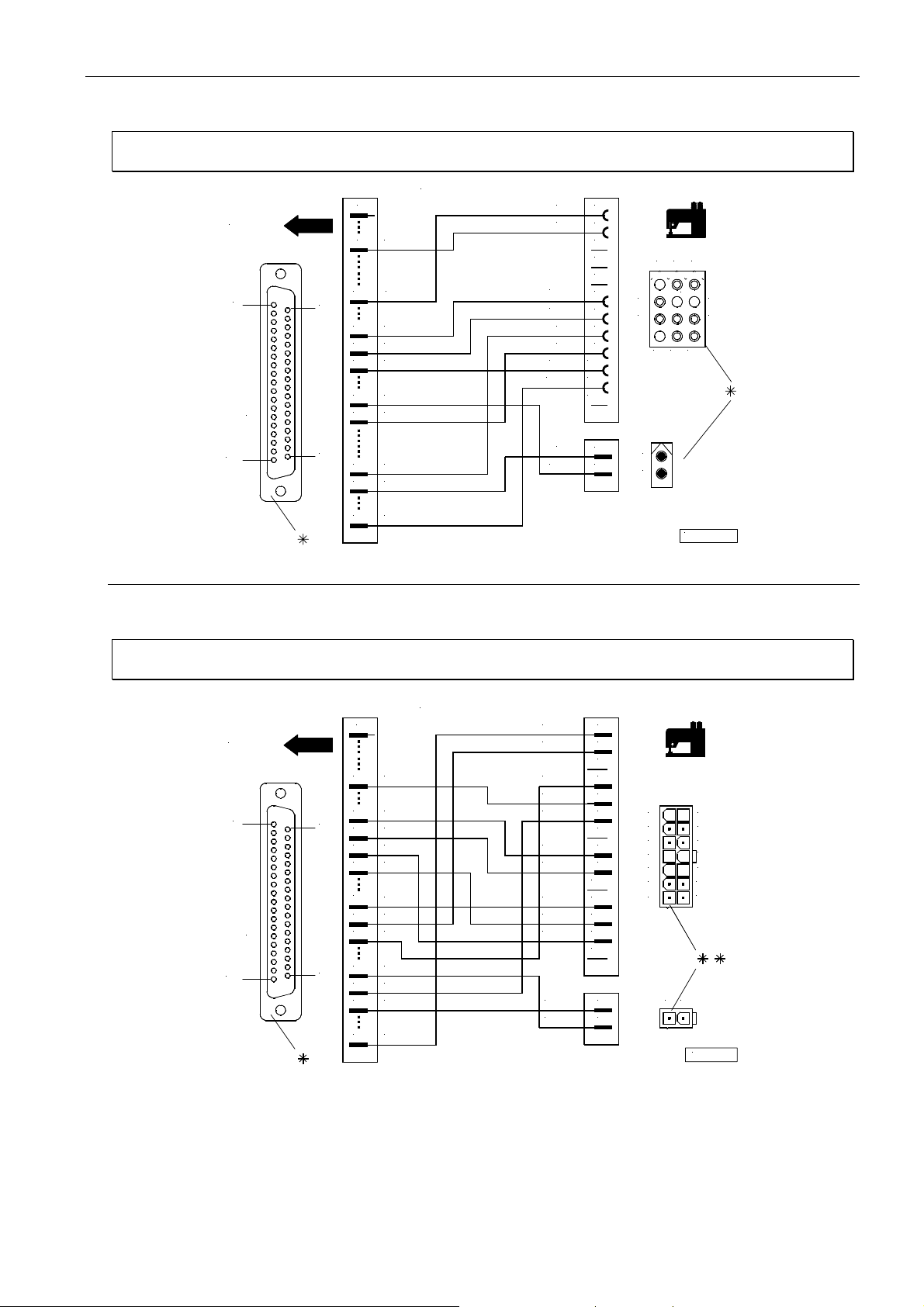
17
1112816
1113132
EFKA AB320A5200
Adapter cord for JUKI model 5550-6
Setting the functional sequence Thread trimming mode ! Set parameter 290 = 14
Setting the functions of the keys Input in1 ! Set parameter 240 = 16
ST2
1
SUB - D - 37
19
20
37
Adapter cord for JUKI model 5550-7
1
0V
4
11 in2
+ 24V
16
+ 24V
17
+ 24V
18
+ 24V
26
27 M3
3435VR
FL
37 M1
Nr.
ZVR0V1
+24V
+24V
VR
FW
+24V
10
11FA1+ 2
12
+24VFL2
2
3
4
5
6
7
8
9
1
2
3
1
5
6
9
12
1
2
8
11
10
KL2235b
4
7
Setting the functional sequence Thread trimming mode ! Set parameter 290 = 14
Setting the functions of the keys Input in1 ! Set parameter 240 = 16
Nr.
ST2
1
19
1
in2
11
17
18
19
26
27
33
34
35
37
+ 24V16
+ 24V
+ 24V
0V
+ 24V
M3
M228
+ 24V
VR
FL
M1
20
SUB - D - 37
37
FA1+ 2
FW
FZ
ZVR 5
VR 6
+ 24V
+ 24V
+ 24V
0V
+ 24V
FL
+ 24V
10
11
12
13
14
1
2
3
4
7
7
8
9
1
2
6
5
4
3
2
1
1 2
14
13
12
11
10
9
8
KL2363
*) Rear view (soldering side) of 37-pin plug (ST2). Front view (component side) of the remaining plugs/sockets.
**) Front view (component side) of the Molex Minifit plugs.
Page 16
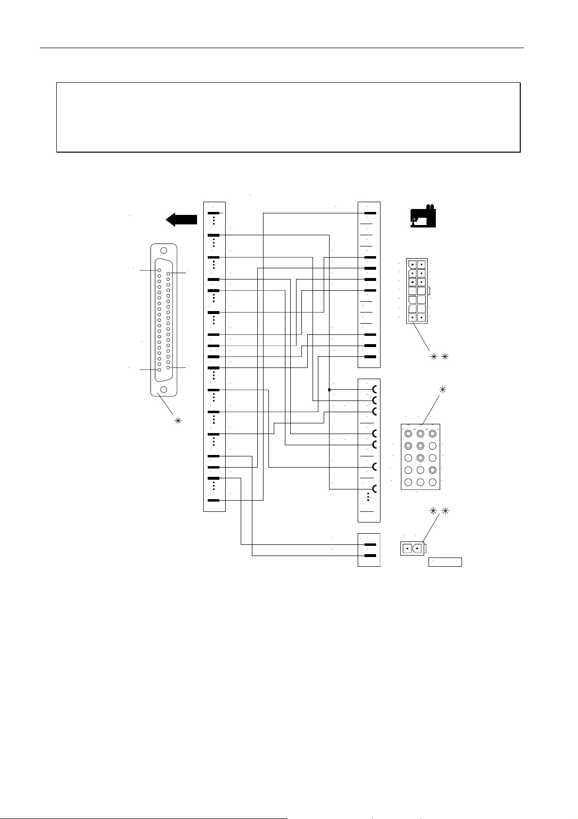
EFKA AB320A5200
18
Adapter cord for JUKI model LU1510-7
Setting the functional sequence Thread trimming mode ! Set parameter 290 = 20
Setting the functions of the keys Input in1 ! Set parameter 240 = 13
(Automatic setting) I nput in3 ! Set parameter 242 = 31
Input in4 ! Set parameter 243 = 32
Input in6 ! Set parameter 245 = 16
Input in7 ! Set parameter 246 = 13
ST2
1
19
SUB - D - 37
20
37
12
16
17
18
19
26
28
30
33
34
35
37
1
4
6
8
9
Nr. 1113200
0V
in3
in4
in7
in6
+ 24V
+ 24V
+ 24V
0V
+ 24V
M2
M6
+ 24V
VR
FL
M1
FA
ZVR
VR
+ 24V
+ 24V
0V
+ 24V
FSP L
0V
S1
HPout
S2
HP in
+ 24V
0V
10
11
12
13
14
10
15
1
2
3
4
5
6
7
8
9
1
2
3
4
5
6
7
8
9
7
6
5 12
4
3
2
1
14
13
11
10
9
8
3 2 1
6 4
9
12
15
5
8
11
14
7
10
13
FL
+ 24V
1
2
1 2
KL2437
in1 = Input high lift for walking foot with speed limitation n10 (operational mode not stored) for knee switch
in3 = Input speed limitation bit 0 (S1)
in4 = Input speed limitation bit 1 (S2)
in6 = Input intermediate backtack
in7 = Input high lift for walking foot with speed limitation n10 (operational mode not stored) for additional
pushbutton at the machine head
*) Rear view (soldering side) of 37-pin plug (ST2). Front view (component side) of the remaining plugs/sockets.
**) Front view (component side) of the Molex Minifit plugs.
Page 17
19
EFKA AB320A5200
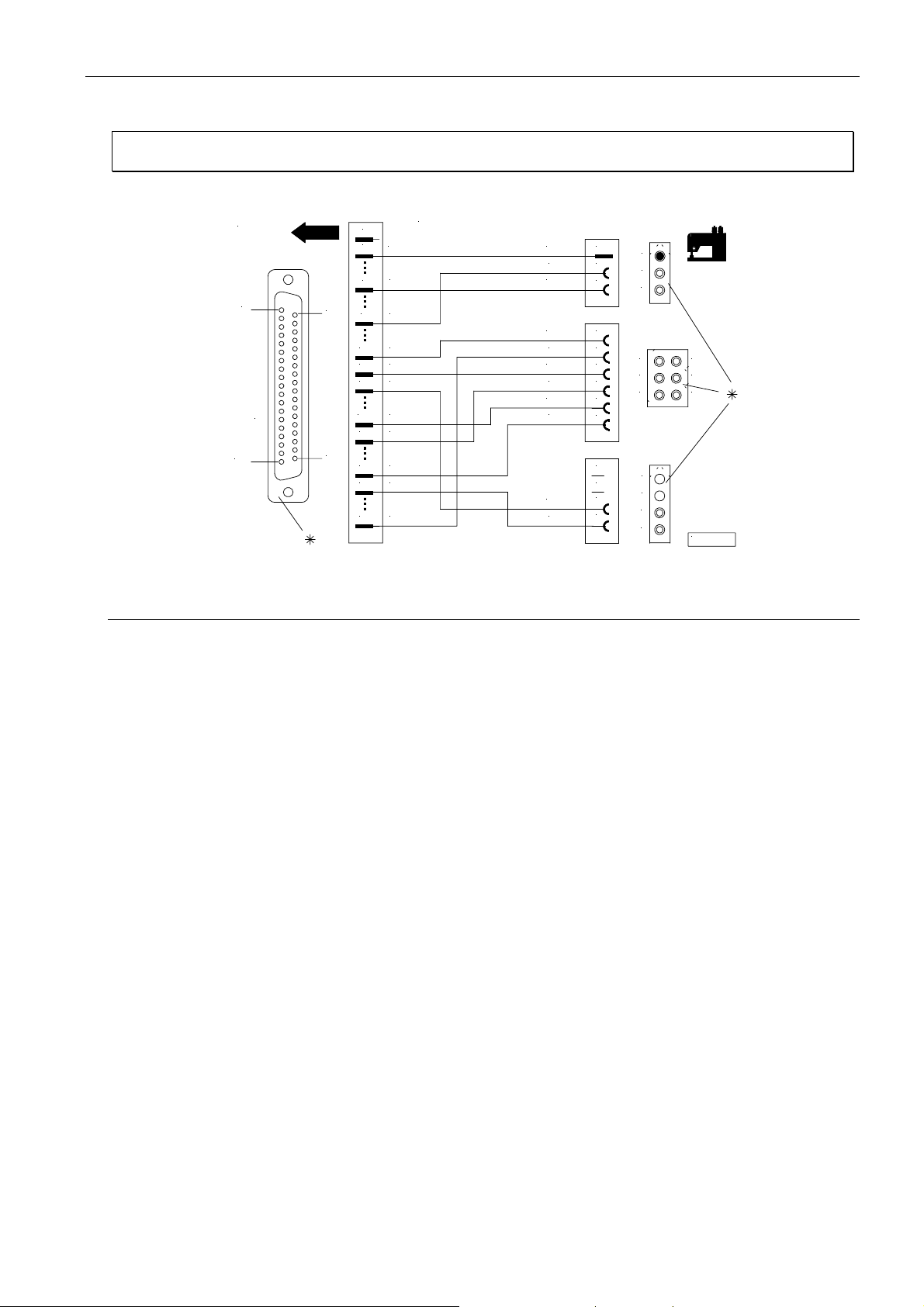
Adapter cord for KANSAI model RX9803
Setting the functional sequence Thread trimming mode ! Set parameter 290 = 5
Setting the functions of the keys Input in1 ! Set parameter 240 = 7
ST2
1
19
1
2
4
20
7
16
17
18
SUB - D- 37
37
26
32
35
37
Nr. 1113130
+5V
0V
in1
+24V
+24V
+24V
+24V
M327
M5
FL
M1
+5V
LSP
0V
+24V
FA
+24V
FW
+24V
ML
+24V
FL
1
1
2
2
3
3
1
2
6
3
5
4
4
5
6
1
1
2
2
3
3
4
4
3
2
1
KL2362
*) Rear view (soldering side) of 37-pin plug (ST2). Front view (component side) of the remaining plugs/sockets.
Page 18
EFKA AB320A5200
20
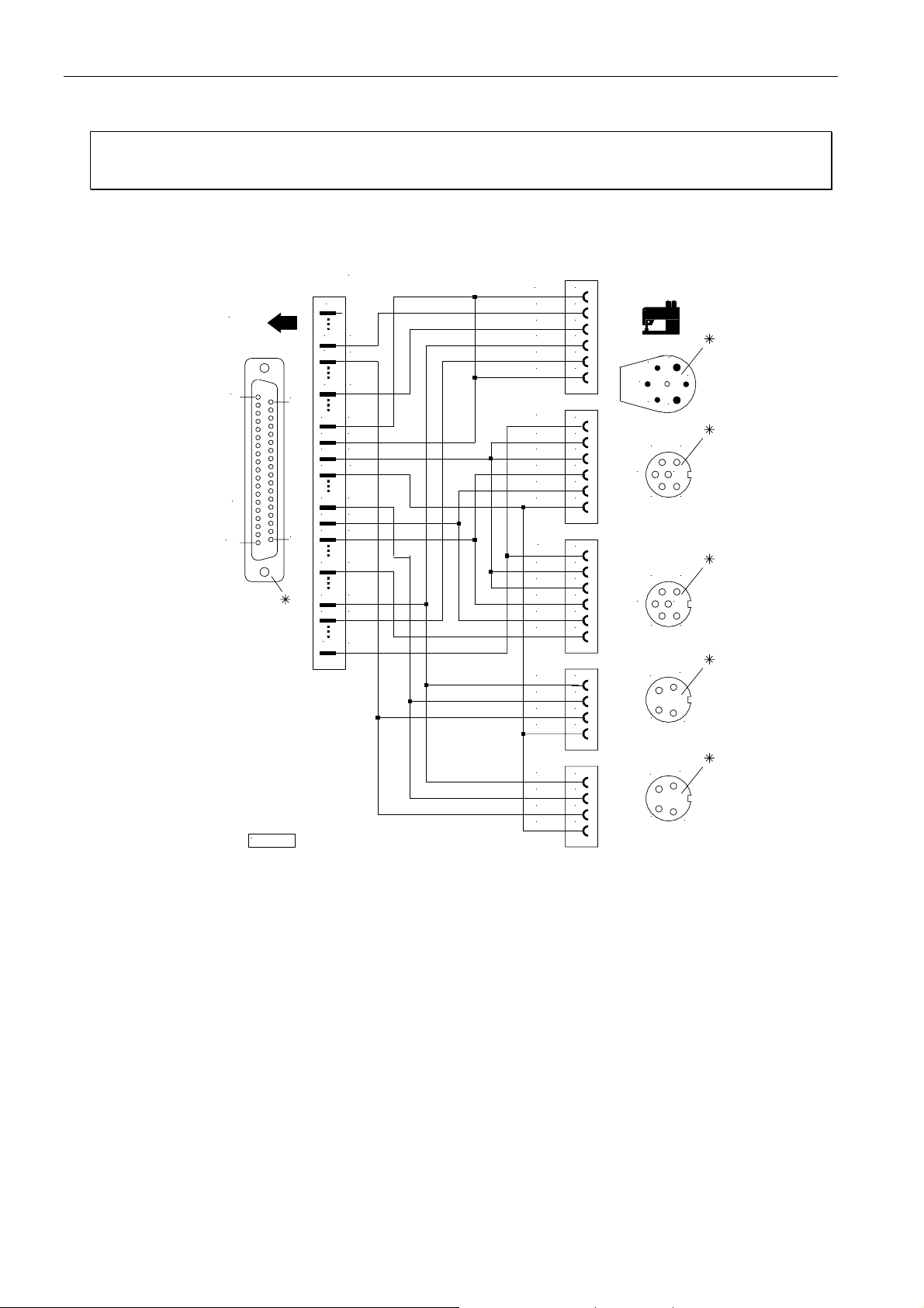
Adapter cord for PFAFF models 563, 953, 1050, 1180 without thread monitor
Setting the functional sequence Thread trimming mode ! Set parameter 290 = 0
Setting the functions of the keys Input in4 ! Set parameter 243 = 12
Input in5 ! Set parameter 244 = 16
ST2
1
SUB - D- 37
19
20
37
Nr. 1112841
1
4
0V
5
in5
8
in4
16
+ 24V
17
+ 24V
18
+ 24V
19
0V
26 + 24V
27
28
M2
32M3M5
34 VR
35 FL
37
M1
+ 24V
0V
FLEX
VR
FL
+ 24V
FA1
+ 24V
+ 24V
FA2
FW
0V
FA1
+ 24V
+ 24V
FA2
FW
ML
VR
+ 24V
ZVR
0V
1
2
3
4
5
6
1
2
3
4
5
6
1
2
3
4
5
6
1
2
3
4
5
6
1
3
3
4
2
3
2
1
6
4
5
2
1
6
4
5
1
2
3
4
VR
1
+ 24V
2
ZVR
3
0V
4
KL2261
*) Rear view (soldering side) of 37-pin plug (ST2) and of the remaining sockets.
1
2
3
4
Page 19
21
EFKA AB320A5200
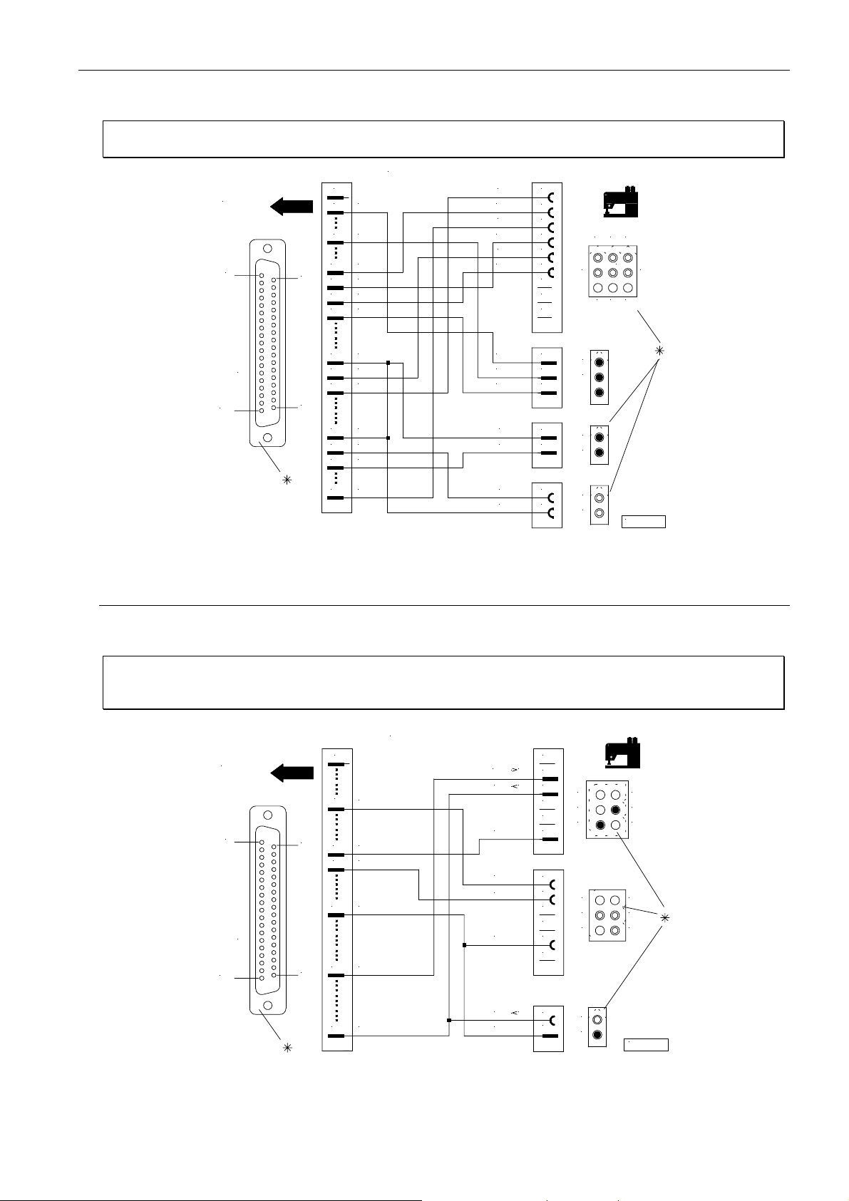
Adapter cord for PEGASUS models W500/UT, W600/UT/MS with or without stitch condensing
Setting the functional sequence Thread trimming mode ! Set parameter 290 = 5
Setting the functions of the keys Input in1 ! Set parameter 240 = 7
Attention!
Nr. 11128 21
1
20
37
2 +5V
7 in1
+24V
16
+24V
17
+24V
18
19 0V
+24V
26
27 M3
28 M2
+24V
33
34 VR
35 FL
37 M1
ST2
1
SUB - D- 37
19
When using this adapter cord on a Pegasus machine, the 9-core cable no. 742373-91 must be
removed from the machine!
FA
+24V
FA
+24V
FW
+24V
+5V
LSP
0V
+24V
FL
STV
+24V
1
2
3
4
5
6
7
8
9
1
2
3
1
2
1
2
2
3
1
5
6
1
2
1
2
1
2
4
8
9
7
KL2240
Adapter cord for PEGASUS backlatch machines
Setting the functional sequence Thread trimming mode ! Set parameter 290 = 8
Setting the functions of the keys Input in1 ! Set parameter 240 = 6
(Automatic setting) I nput in3 ! Set parameter 242 = 10
Nr . 1113234
ST2
1
19
1
4
0V
20
67in3
in1
19 0V
SUB - D- 37
28 M2
37
37 M1
Ped
Ped -1
N- AUTO
0V
LSP
0V
Ped -1
0V
1
1
=
2
3
=
=
4
5
6
1
2
3
4
5
6
1
2
4
5
6
6
5
4 1
1
2
1
2
3
3
2
KL2458
*) Rear view (soldering side) of 37-pin plug (ST2). Front view (component side) of the remaining plugs/sockets.
Page 20
EFKA AB320A5200
22
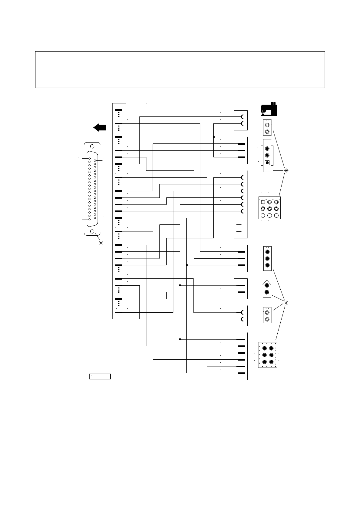
Adapter cord for PEGASUS model MHG
Setting the functional sequence Thread trimming mode ! Set parameter 290 = 24
Setting the functions of the keys Input in1 ! Set parameter 240 = 6
Input in2 ! Set parameter 241 = 13
Input in3 ! Set parameter 242 = 28
Input in4 ! Set parameter 243 = 22
ST2
1
SUB - D- 37
19
20
37
1
+5V
2
0V4
6 in3
7
in1
8
in4
11
in2
+15V
15
16
+24V
17
+24V
18
+24V
19
0V
23
M7
25
M9
26
+24V
27
M3
28
M2
M5
32
33 +24V
3537FL
Nr.1113267
in4
0V
0V
SEN
+15V
FA
FA
+24V
FW
+24V
+5V
LSP
0V
+24V
FL
1
2
1
2
3
1
2+24V
3
4
5
6
7
8
9
1
2
3
1
2
1
2
1
2
3
23 1
5
6
1
2
3
1
2
4
79 8
M1
KL2482
M5
+24V
+24V
M7
+24V
M9
in2
0V
1
2
1
2
3
4
5
6
1
2
4
5
6
1
2
3
*) Rear view (soldering side) of 37-pin plug (ST2). Front view (component side) of the remaining plugs/sockets.
Page 21
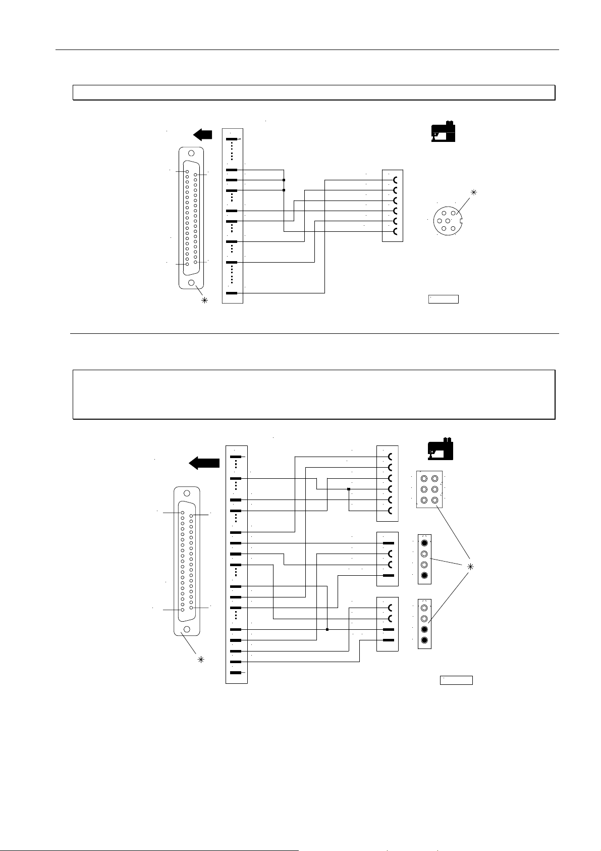
23
EFKA AB320A5200
Adapter cord for RIMOLDI model F27
Setting the functional sequence Thread trimming mode ! Set parameter 290 = 5
Nr. 1113096
20
37
1
16 + 24V
1718+ 24V
+ 24V
M3
27
M2
28
M532
35 FL
37
M1
FW
1
ML
2
FAO
FAU
FL
+ 24V
3
4
5
6
2
356
4
KL2346
1
Input in3 ! Set parameter 242 = 16
ST2
1
SUB - D- 37
19
Adapter cord for SINGER models 211, 212 and 591
Setting the functional sequence Thread trimming mode ! Set parameter 290 = 2
(Singer model 212UTT)
Setting the functions of the keys Input in1 ! Set parameter 240 = 1
ST2
1
19
SUB - D- 37
20
37
1
0V
4
6 in3
7 in1
+ 24V
16
+ 24V
17
+ 24V
18
19 0V
26
27 M3
28 M2
+ 24V
33
3435VR
FL
M436
37
Nr. 11128 24
+ 24V
FW /FSPL
NHT
0V
ZVR
0V
+ 24V
VR
+ 24V
FA2/FA
FL
0V
+ 24V
FL 1
1
2
3
6
4
5
5
4
6
1
1
2
2
3
3
4
4
1
1
2
2
3
3
4
4
3
2
1
KL2243
*) Rear view (soldering side) of 37-pin plug (ST2). Front view (component side) of the remaining plugs/sockets.
Page 22
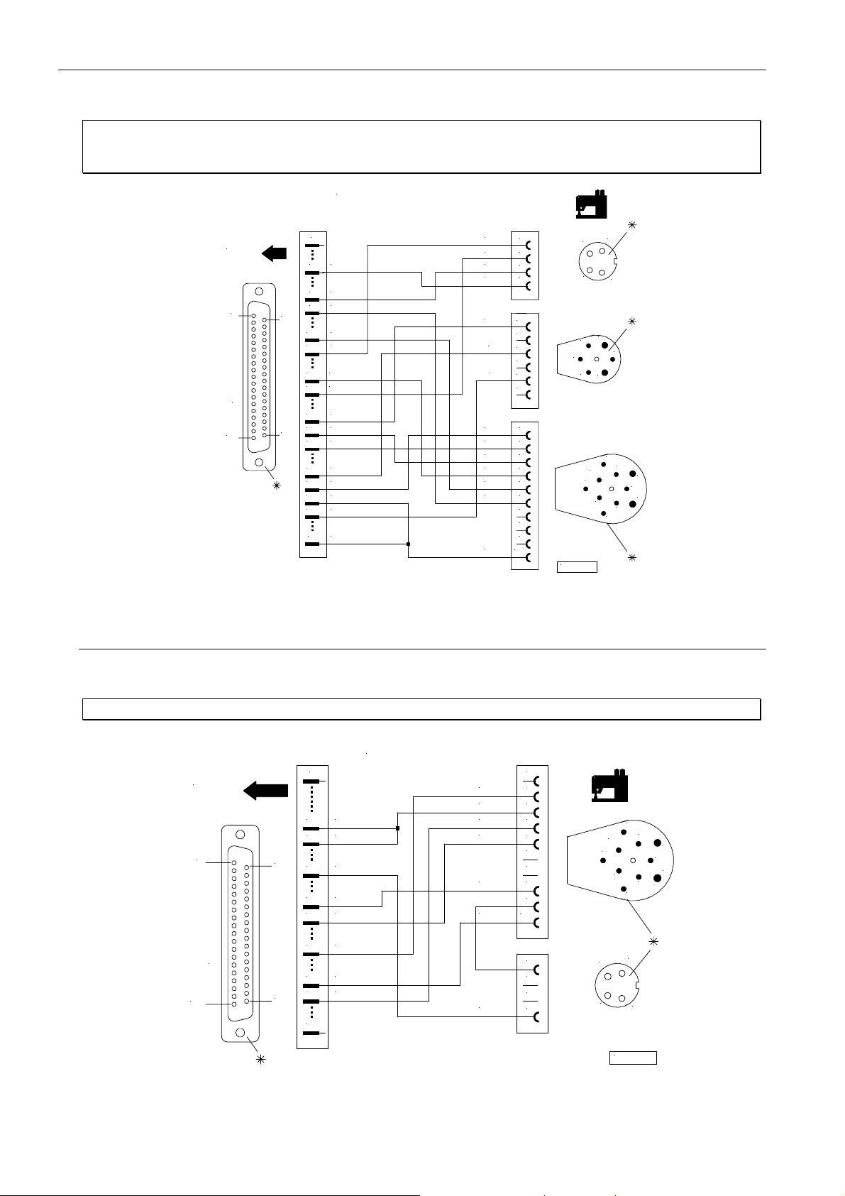
EFKA AB320A5200
24
Adapter cord for UNION SPECIAL models CS100 and FS100
Setting the functional sequence Thread trimming mode ! Set parameter 290 = 4
Setting the functions of the keys Input in1 ! Set parameter 240 = 6
Input in3 ! Set parameter 242 = 6
Nr. 1112905
+ 24V
POS1
LSP
0V
+ 24V
ML
FL
+ 24V
FA- V
FW
0V
+ 15V
LSP
FA- R
1
2
3
4
1
2
3
4
5
6
1
2
3
4
5
6
7
8
9
10
ST2
1
SUB - D- 37
19
20
37
1
4
0V
6
in3
7
in1
15
+ 15V
16
+ 24V
19
0V
20
POS1
26
+ 24V
27
M3
28
M2
32
M5
33
+ 24V
34
VR
35 FL
37 M1
in1 = Input machine run blockage for thread trimming control proximity switch
in3 = Input machine run blockage for thread monitor
2
3
6
1
2
KL2306
1
4
5
4
3
9
8
10
1
7
6
5
2
4
3
Adapter cord for UNION SPECIAL model 63900AMZ
Setting the functional sequence Thread trimming mode ! Set parameter 290 = 10
Nr. 1112823
ST2
1
19
SUB - D - 37
20
37
1
+ 24V
16
+ 24V
17
19 0V
27 M3
28 M2
32 M5
34 VR
35 FL
37
ML
+ 24V
FL
FA- V
FW
FA- R
0V
10
1
2
3
4
5
6
7
8
9
1
9
8
10
1
2
2
7
6
5
4
3
1
2
3
4
3
4
KL2242
*) Rear view (soldering side) of 37-pin plug (ST2) and of the remaining sockets.
Page 23
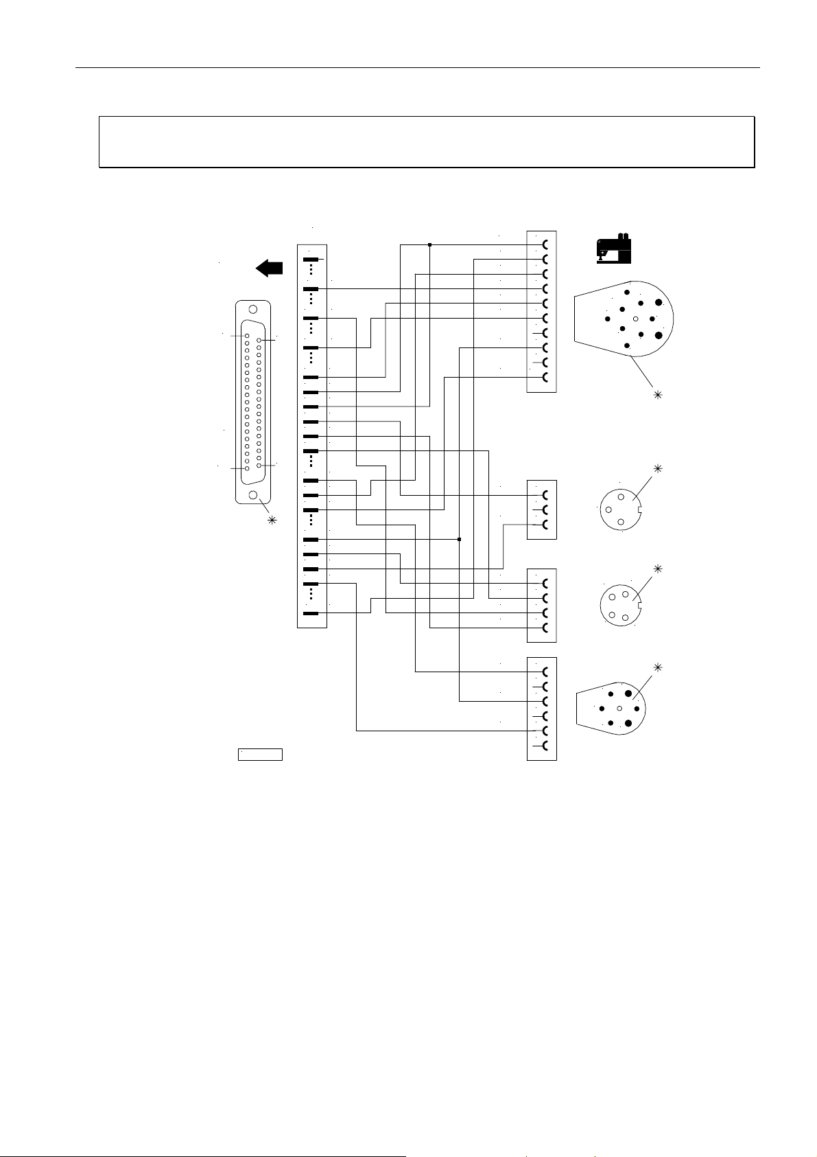
25
EFKA AB320A5200
Adapter cord for UNION SPECIAL model 34700 with stitch lock
Setting the functional sequence Thread trimming mode ! Set parameter 290 = 5
Setting the functions of the keys Input in8 ! Set parameter 247 = 7
Input in9 ! Set parameter 248 = 6
ST2
1
SUB - D- 37
19
Nr. 11128 44
1
4
10
20
13
15
16
17
18
19
20
37
26
27
28
32
33
34
0V
in8
in9
+ 15V
+ 24V
+ 24V
+ 24V
0V
POS1
+ 24V
M3
M2
M5
+ 24V
VR
FL35
M137
+ 24V
FA
FW
0V
+ 15V
LSP
NKFA8
+ 24V
STV
+ 24V
POS1
STOP
0V
10
1
2
3
4
5
6
7
9
1
2
3
1
2
3
4
9
8
10
1
2
1
2
3
2
3
7
6
5
4
3
1
4
+ 24V
ML
FL
KL2260
*) Rear view (soldering side) of 37-pin plug (ST2) and of the remaining sockets.
1
2
3
4
5
6
5
6
1
4
2
3
Page 24
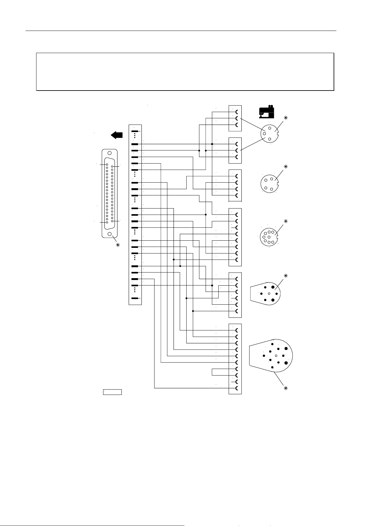
EFKA AB320A5200
26
Adapter cord for UNION SPECIAL models 34000 and 36200
Setting the functional sequence Thread trimming mode ! Set parameter 290 = 4
Setting the functions of the keys Input in1 ! Set parameter 240 = 6
Input in3 ! Set parameter 242 = 6
Input in4 ! Set parameter 243 = 18
Input in5 ! Set parameter 244 = 12
ST2
1
SUB - D - 37
19
20
37
Nr. 1112865
1
4
0V
5
in5
6
in3
7
in1
8
in4
15
+15V
16
+24V
17
+24V
19
0V
20
POS1
21
POS2
22
GEN
26
+24V
27 M3
28
M2
32
M5
33
+24V
34
VR
35
FL
37
0V
FLAT- S
FLEX
0V
FLAT- S
FLEX
+24V
POS1
LSP
0V
+24V
GEN
ML
FL
POS2
POS1
0V
+24V
FW
ML
FL
FA- V
1
2
2
2
3
1
4
2
5 7
6
1
2
1
3
1
4
6
8
3
5
4
3
3
1
2
3
1
2
3
4
1
2
3
4
5
6
7
8
1
2
3
4
5
6
+24V
1
FA- V
2
FW
3
0V
4
+15V
5
LSP
6
7
8
9
10
FA- R
KL2289
in1 = Input machine run blockage for thread trimming control proximity switch
in3 = Input machine run blockage for thread monitor
in4 = Input unlocking the chain corresponds to function flatseamer (FLAT-S)
*) Rear view (soldering side) of 37-pin plug (ST2) and of the remaining sockets.
9
8
10
1
2
7
6
5
4
3
Page 25

27
N
1112818
EFKA AB320A5200
Adapter cord for YAMATO chainstitch machines VC series
Setting the functional sequence Thread trimming mode ! Set parameter 290 = 5
Setting the functions of the keys Input in1 ! Set parameter 240 = 7
1
ST2
1
SUB-D-37
19
20
37
4
0V
7 in1
+24V
16
+24V
17
+24V
18
27 M3
3435VR
FL
37 M1
Adapter cord for YAMATO chainstitch machines VG series
r.
+24V
FA
FW
0V
LSP
+24V
FL
STV
+24V
1
1
2
2
3
3
4
4
1
1
2
2
3
3
1
1
2
2
1
1
2
2
KL2237
Setting the functional sequence Thread trimming mode ! Set parameter 290 = 5/21
Setting the functions of the keys Input in1 ! Set parameter 240 = 7
Nr. 1113178
0V
in1
+ 24V
+ 24V
+ 24V
+ 24V
M3
M5
+ 24V
VR
FL
M1
+ 24V
+ 24V
+ 24V
+ 24V
+ 24V
FL
FA
FW
STV
ML
0V
LSP
10
11
12
13
14
15
1
2
3
4
5
6
7
8
9
10
5
4
3
2
1
9
8
7
6
KL2405
15
14
13
12
11
ST2
1
19
SUB - D- 37
20
37
1
4
7
16
17
18
26
27
32
33
34
35
37
*) Rear view (soldering side) of 37-pin plug (ST2). Front view (component side) of the remaining plugs/sockets.
Page 26
EFKA AB320A5200
28
Adapter cord for YAMATO backlatch machine model ABT3
Setting the functional sequence Thread trimming mode ! Set parameter 290 = 9
Setting the functions of the keys Input in1 ! Set parameter 240 = 6
(Automatic setting) I nput in3 ! Set parameter 242 = 10
Nr. 1112826
1
20
37
24+5V
0V
67in3
in1
POS2Q
21
28 M2
+24V
33
37 M1
R
ST2
1
SUB - D- 37
19
Adapter cord for YAMATO backlatch machine models ABT13 and ABT17
Setting the functional sequence Thread trimming mode ! Set parameter 290 = 9
Setting the functions of the keys Input in1 ! Set parameter 240 = 6
(Automatic setting) I nput in3 ! Set parameter 242 = 10
Input in4 ! Set parameter 243 = 34
0V
Ped 1
=
Ped -1
=
N- AUTO
LSP
+5V
POS2Q
1
2
3
4
4
5
5
6
6
1
2
6
3
5
4
4
5
6
1
1
2
2
1
2
3
3
2
1
KL2244
ST2
1
19
Nr. 1113205
1
2
+5V
4
0V
6
7
8
21
28
37
in3
in1
in4
POS2Q
M2
M1
20
SUB - D- 37
37
0V
Ped
=
Ped
-1
=
N12- AUTO
LSP
+5V
N9-AUTO
POS2Q
1
1
2
3
4
4
5
5
6
6
1
2
6
3
5
4
4
5
6
1
2
6
3
5
4
4
5
6
1
2
3
3
2
1
3
2
1
KL2439
*) Rear view (soldering side) of 37-pin plug (ST2). Front view (component side) of the remaining plugs/sockets.
Page 27
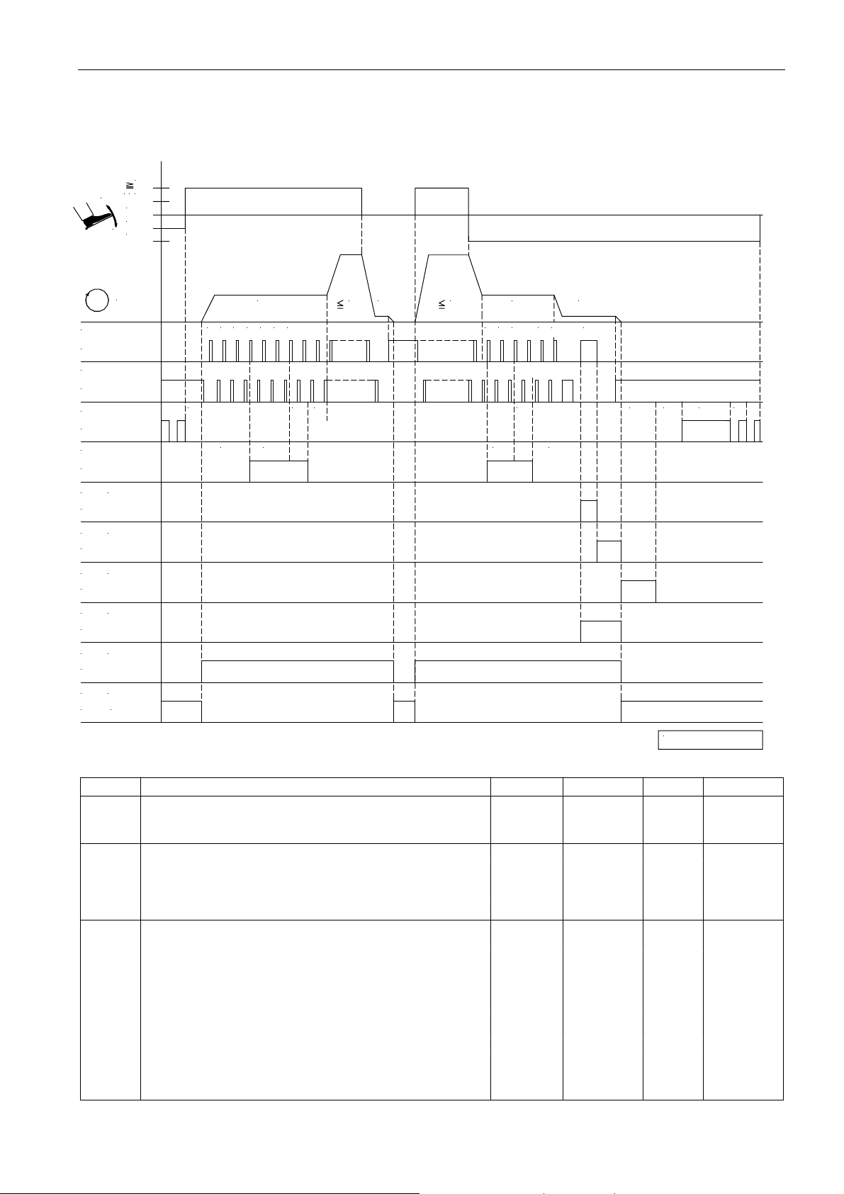
5 Timing Diagrams
Mode 0 (lockstitch)
1
/
21
-
0
-1
+
-2
29
EFKA AB320A5200
n
POS.1
ST2/20
POS.2
ST2/21
FL
ST2/35
VR
ST2/34
(FA1)
M1
ST2/37
(FA2)
M2
ST2/28
(FW )
M3
ST2/27
(FA1+ 2)
M4
ST2/36
(M L)
M5
ST2/32
(M S T)
M6
30
ST2/
n2
310n32 3 1 2
t3
c2
t8 t1
c1
n2n1
0 1 2
c3
n4
t9
1 2n73
c4
t6 t7
t4 t5
0256/M O DE- 0
Mark Function Parameter Control V810 V820
Mode 0 290 = 0
Double start backtack with stitch correction On S2 key 1 key 1 key
Double end backtack with stitch correction On S3 key 2 key 4 key
n1 Positioning speed 110
n2 Maximum speed 111
n3 Start backtack speed 112
n4 End backtack speed 113
n7 Trimming speed 116
t1 Delay until speed release after start backtack 200
t3 Start delay from lifted sewing foot 202
t4 Full power of sewing foot lifting 203
t5 Pulsing of sewing foot lifting 204
t6 Thread wiper ON period 205
t7 Sewing foot switch-on delay after thread wiper 206
t8 Start backtack stitch correction 150
t9 End backtack stitch correction 151
c2 Start backtack stitches forward 000
c1 Start backtack stitches backward 001
c3 End backtack stitches backward 002
c4 End backtack stitches forward 003
Page 28
EFKA AB320A5200
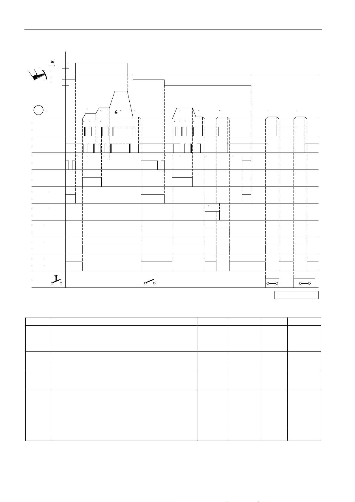
Mode 2 (lockstitch)
/ 0112
-
-1
+
-2
30
n
POS.1
ST2/20
POS.2
ST2/21
FL
ST2/35
VR
ST2/34
M4
ST2/36
M2
ST2/28
(FS P L)
M3
ST2/27
(M L)
M5
ST2/32
(M S T)
M6
30
ST2/
NHT
(FL1 )
(FA)
n6
0 1
2 3 0
SSc
c1
t3
t1 t3
n1n3 n2
1 2 3
c3
tF A
kt2
n7n4 n7
tF L
n1 n1
0256/M O DE- 2
Mark Function Parameter Control V810 V820
Mode 2 290 = 2
Softstart 134 = 1
Single start backtack On S2 key 1 key 1 key
Single end backtack On S3 key 2 key 4 key
n1 Positioning speed 110
n2 Maximum speed 111
n3 Start backtack speed 112
n4 End backtack speed 113
n6 Softstart speed 115
n7 Trimming speed 116
t1 Delay until speed release after start backtack 200
t3 Start delay from lifted sewing foot 202
tFL Switch-on delay of sewing foot lifting 211
kt2 Thread trimmer ON period 283
tFA Stop time for thread trimmer 253
SSc Softstart stitches 100
c1 Start backtack stitches backward 001
c3 End backtack stitches backward 002
Page 29
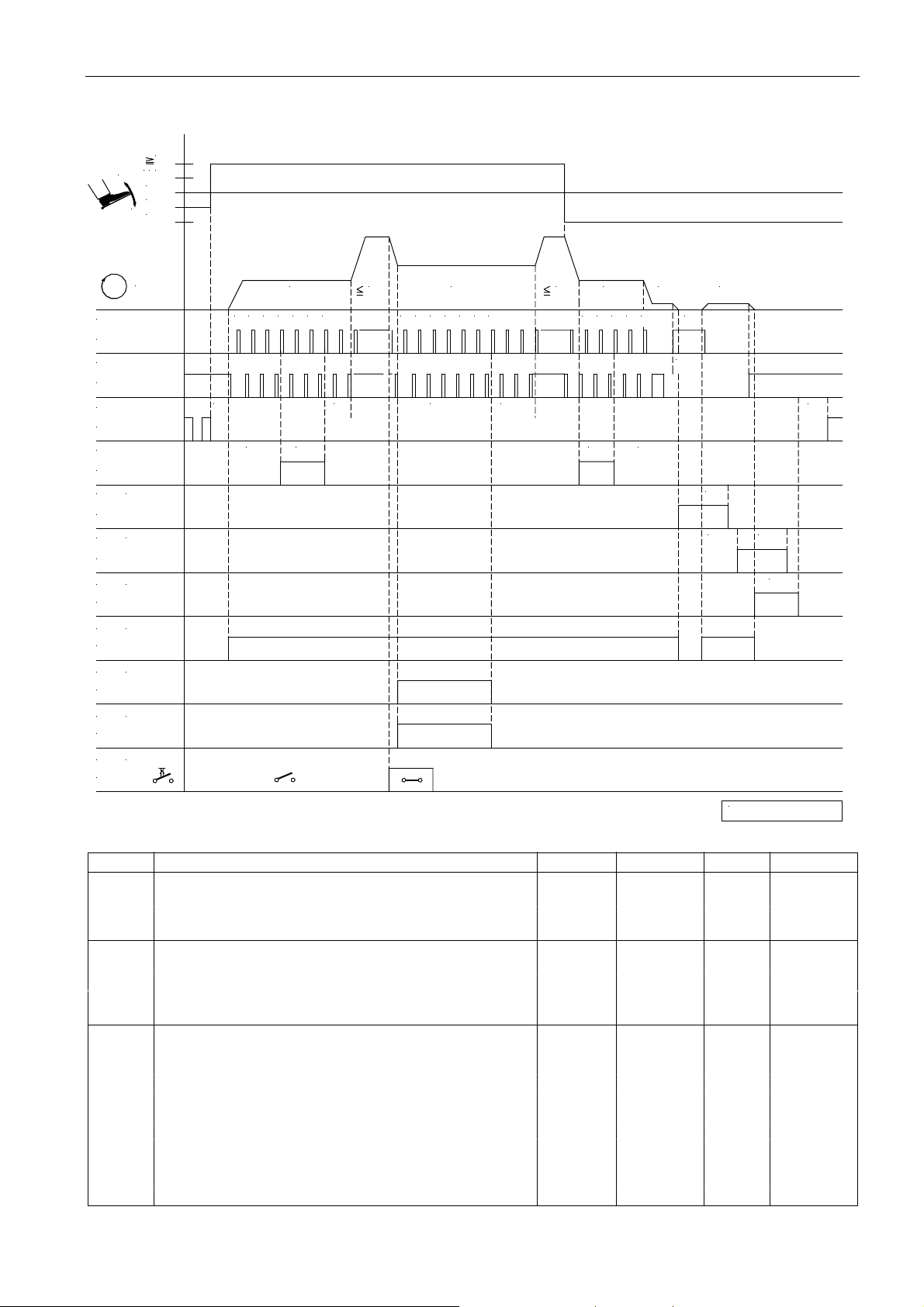
Mode 3 (lockstitch)
/121
-
0
-1
+
-2
31
EFKA AB320A5200
n
POS.1
ST2/20
POS.2
ST2/21
FL
ST2/35
VR
ST2/34
M1
(FA)
ST2/37
(FS P L)
M4
ST2/36
M3
(FW )
ST2/27
M2
(M L)
ST2/28
M5
(H P )
ST2/32
(LH P )
M11
ST2/31
0
1n32 3 1 2 3
t3
c2 c1
n2 n10
t1
1 2 3 4 5
cHP
n2
6
7
tH P
0
1 2n41 2
c3
c4
n7
n7
3
tF A
t7
iFA
FSE FSA
t6
(H P )
in1
ST2/7
0256/M O DE- 3
Mark Function Parameter Control V810 V820
Mode 3 290 = 3
Double start backtack On S2 key 1 key 1 key
Double end backtack On S3 key 2 key 4 key
High lift for walking foot 137 = 1
n2 Maximum speed 111
n3 Start backtack speed 112
n4 End backtack speed 113
n7 Trimming speed 116
n10 High lift walking speed 117
t6 Thread wiper ON period 205
t7 Sewing foot switch-on delay after thread wiper 206
iFA Activation angle of the thread trimmer 250
FSA Thread tension release ON period 251
FSE Thread tension release delay depending on angle 252
c2 Start backtack stitches forward 000
c1 Start backtack stitches backward 001
c3 End backtack stitches backward 002
c4 End backtack stitches forward 003
tHP High lift walking speed run-out time 152
cHP Stitch counting high lift for walking foot 185
Page 30
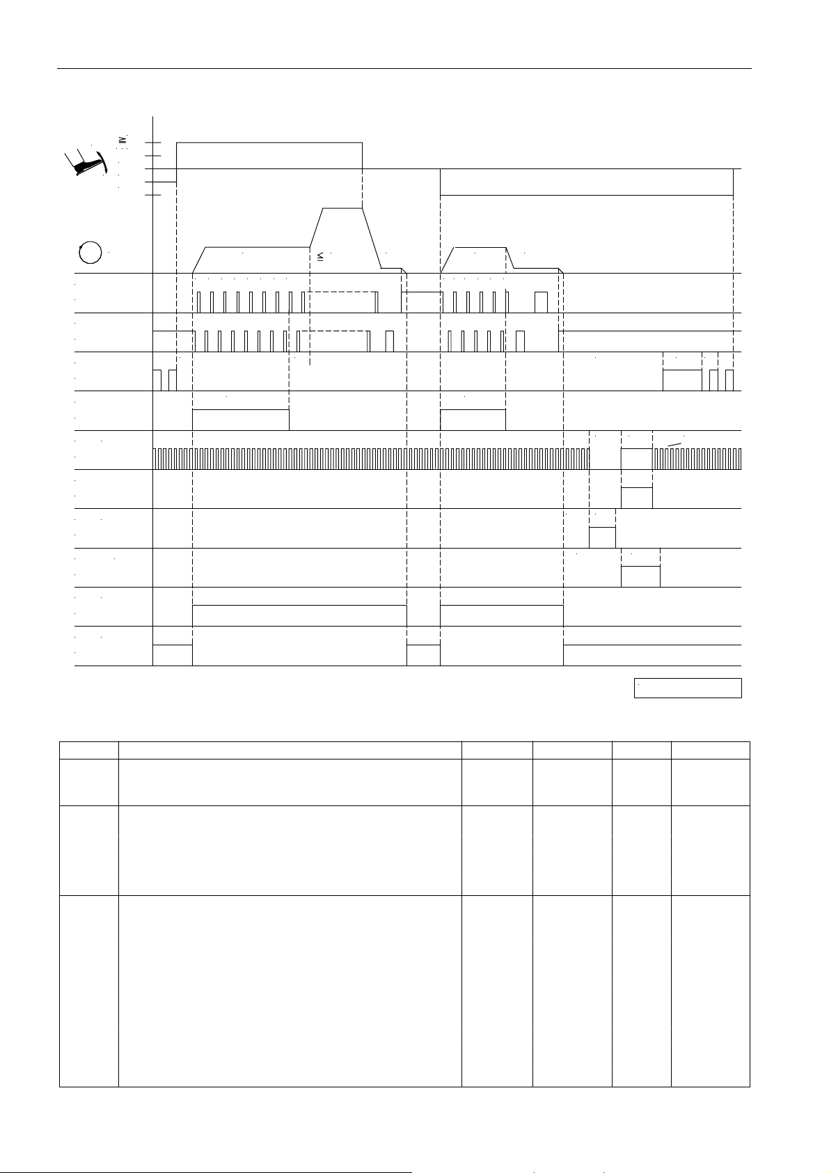
EFKA AB320A5200
Mode 4 (chainstitch)
1
-
1/2
0
+
-1
-2
32
n
POS.1
ST2/20
POS.2
ST2/21
FL
ST2/35
M4
ST2/36
(FA- R )STV
ST2/34
M1
ST2/37
(FA- V )M2
ST2/28
M3 (FW )
ST2/27
M5 (M L)
ST2/32
M6
(M S T)
ST2/30
n3
0 1 2 3t34 5 6 7
c1
n2
t1
n1
n4
0 1 2 3 4 5
c3
n7
kdF
kt2kd2
t4
t5
kt1kd1
kt3kd3
t1 1
0256/M O DE- 4
Mark Function Parameter Control V810 V820
Mode 4 290 = 4
Start stitch condensing On S2 key 1 key 1 key
End stitch condensing On S3 key 2 key 4 key
n1 Positioning speed 110
n2 Maximum speed 111
n3 Start backtack speed 112
n4 End backtack speed 113
n7 Trimming speed 116
n12 Automatic speed 118
t1 Delay until speed release after start backtack 200
t3 Start delay from lifted sewing foot 202
t11 Holding power output “stitch condensing” of the thread 213
trimmer backward
kd1 Delay time of the thread trimmer backward 280
kt1 ON period of the thread trimmer backward 281
kd2 Delay time of the thread trimmer forward M2 282
kt2 ON period of the thread trimmer forward M2 283
kd3 Delay time of the thread wiper M3 284
kt3 ON period of the thread wiper M3 285
kdF Switch-on delay of sewing foot lifting 288
c1 Stitch counting of start stitch condensing 001
c3 Stitch counting of end stitch condensing 002
Page 31
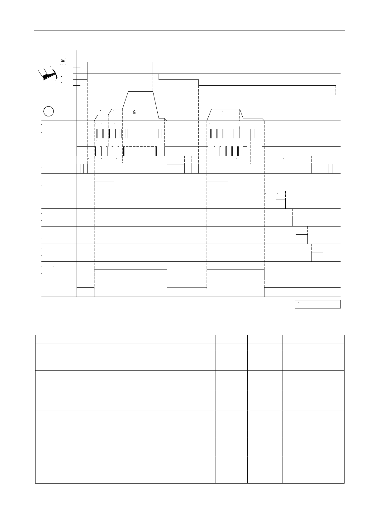
Mode 5 (chainstitch)
1
/
2
1
-
0
-1
+
-2
33
EFKA AB320A5200
n
POS.1
ST2/20
POS.2
ST2/21
FL
ST2/35
STV
ST2/34
M1
ST2/37
M2
ST2/28
M3
ST2/27
M4
ST2/36
M5 (M L)
ST2/32
(M S T)M6
ST2/30
0 1n62 3
SSc
t3
n3 n1n2
t1c1
n4
320 1
t4 t5 t3 c3 c4
n7
21
kdF
kd1 kt1
kt2kd2
kd3 kt3
kt4kd4
0256/M O DE- 5
Mark Function Parameter Control V810 V820
Mode 5 290 = 5
Softstart 134 = 1
Start stitch condensing On S2 key 1 key 1 key
End stitch condensing On S3 key 2 key 4 key
n1 Positioning speed 110
n2 Maximum speed 111
n3 Start stitch condensing speed 112
n4 End stitch condensing speed 113
n6 Softstart speed 115
n7 Trimming speed 116
t1 Delay until speed release after start backtack 200
t3 Start delay from lifted sewing foot 202
t4 Full power of sewing foot lifting 203
t5 Pulsing of sewing foot lifting 204
c1 Stitch counting of start stitch condensing 001
c3 Stitch counting of end stitch condensing 002
c4 Stitch counting at the seam end without stitch regulator 003
SSc Softstart stitches 100
kdF Switch-on delay of sewing foot lifting 288
kd1-kd4 Delay times of outputs M1...M4 280/2/4/6
kt1-kt4 ON periods of outputs M1...M4 281/3/5/7
Page 32
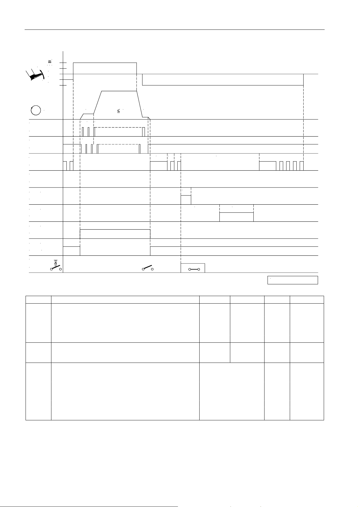
EFKA AB320A5200
Mode 5 (chainstitch) Union Special, bag sewing machine
1
/
21
-
0
-1
+
-2
34
n
POS.1
ST2/20
POS.2
ST2/21
FL
ST2/35
STV
ST2/34
(IMP)
M2
ST2/28
(B R )M3
ST2/27
(M L)
M5
ST2/32
(M S T)
M6
30
ST2/
in 1 ...i10
ST2/..
n6
2
0 1
SSc
t3
n2
n1
t4 t5
kdF
kt2
kd3 kt3
0256/M O DE- 5a
Mark Function Parameter Control V810 V820
Mode 5 290 = 5
Softstart 134 = 1
SAk “Hot thread chain cutting“ (M3) by means of knee switch 198 = 1
and sewing foot lift by means of pedal
in1...i10 Function “hot thread chain cutting“ (M3) by means of knee 24x = 42
switch
n1 Positioning speed 110
n2 Maximum speed 111
n6 Softstart speed 115
t3 Start delay from lifted sewing foot 202
t4 Full power of sewing foot lifting 203
t5 Pulsing of sewing foot lifting 204
SSc Softstart stitches 100
kd2 Delay time for output M2 282 = 0
kt2 ON period for output M2 283 = 50ms
kd3 Delay time for output M3 284 = 1500ms
kt3 ON period for output M3 285 = 1400ms
kdF Switch-on delay of sewing foot lifting 288 = 2550ms
Settings using parameter 198:
Parameter 198 = 0 The signals hot thread chain cutting and sewing foot lift are enabled by means of pedal.
Parameter 198 = 1 The signal hot thread chain cutting is enabled by means of knee switch and sewing foot lift by
means of pedal.
Parameter 198 = 2 The signal hot t hread chain cutting is enabled by means of pedal and sewing foot lift by means of
knee switch.
Page 33
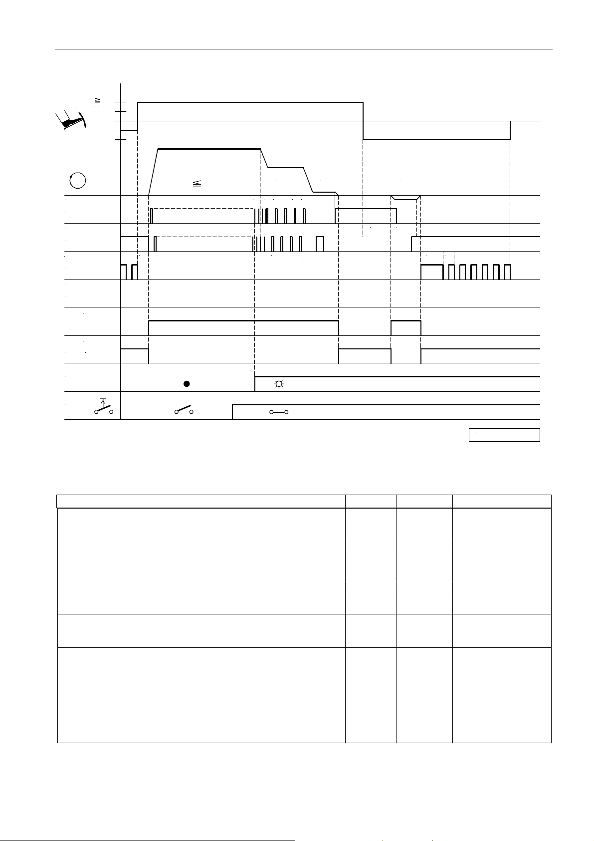
35
Mode 4, 5, 6 or 7 (function “unlocking the chain” with light barrier)
1
1/2
-
0
-1
+
-2
EFKA AB320A5200
n
POS.1
ST2/20
POS.2
ST2/21
FL
ST2/35
STV
ST2/34
(M L)
M5
ST2/32
(M S T)
M6
30ST2/
LS
EN TK
n2
t3
LS
60 3 4 5n57
n1
n1
drd ird
t4 t5
0256/ ENTK- 1
Mark Function Parameter Control V810 V820
Mode 5 290 = 5
drE Direction of motor rotation Clockwise 161 = 0
Frd Reverse motor rotation 182 = 1
Basic position 2 On S5 key 4 key 7 key
End stitch condensing and thread trimmer *) On
Light barrier 009 = ON
Unlock the chain automatically with light barrier 190 = 2
in7 Machine run blockage effective with open contact 246 = 6
in8 Automatic speed n12 without pedal 247 = 10
in.. Assign the function “unlocking the chain” to an output 2..
n1 Positioning speed 110
n2 Maximum speed 111
n5 Speed after light barrier sensing 114
t3 Start delay from lifted sewing foot 202
t4 Full power of sewing foot lifting 203
t5 Pulsing of sewing foot lifting 204
LS Light barrier compensating stitches 004
ird Number of reversing increments 180
drd Switch-on delay of reverse motor rotation 181
tGn Speed gate damping period 222
dGF Speed gate 2 224 = 1
kdF Switch-on delay of sewing foot lifting 288
*) When unlocking the chain, the functions “stitch condensing” and “thread trimmer” are suppressed!
Page 34
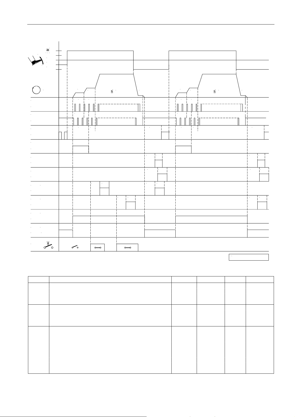
EFKA AB320A5200
Mode 4, 5, 6 or 7 (function “unlocking the chain”)
1
1/2
-
0
-1
+
-2
36
POS.1
ST2/20
POS.2
ST2/21
FL
ST2/35
STV
ST2/34
(ML)
M5
ST2/32
(MST)
M6
30
ST2/
ENTK
n
t3
n2 n1
n2 n1n1
drd Ird drd
n1
Ird
0256/ENTK-2
Mark Function Parameter Control V810 V820
Mode 5 290 = 5
drE Direction of motor rotation Clockwise 161 = 0
Frd Reverse motor rotation 182 = 1
Basic position 2 On S5 key 4 key 7 key
End stitch condensing and thread trimmer *) On
in7 Machine run blockage effective with open contact 246 = 6
in8 Automatic speed n12 without pedal 247 = 10
in.. Assign the function “unlocking the chain” to an output 2..
n1 Positioning speed 110
n2 Maximum speed 111
t3 Start delay from lifted sewing foot 202
t4 Full power of sewing foot lifting 203
t5 Pulsing of sewing foot lifting 204
ird Number of reversing increments 180
drd Switch-on delay of reverse motor rotation 181
tGn Speed gate damping period 222
dGF Speed gate 2 224 = 1
*) When unlocking the chain, the functions “stitch condensing” and “thread trimmer” are suppressed!
Page 35
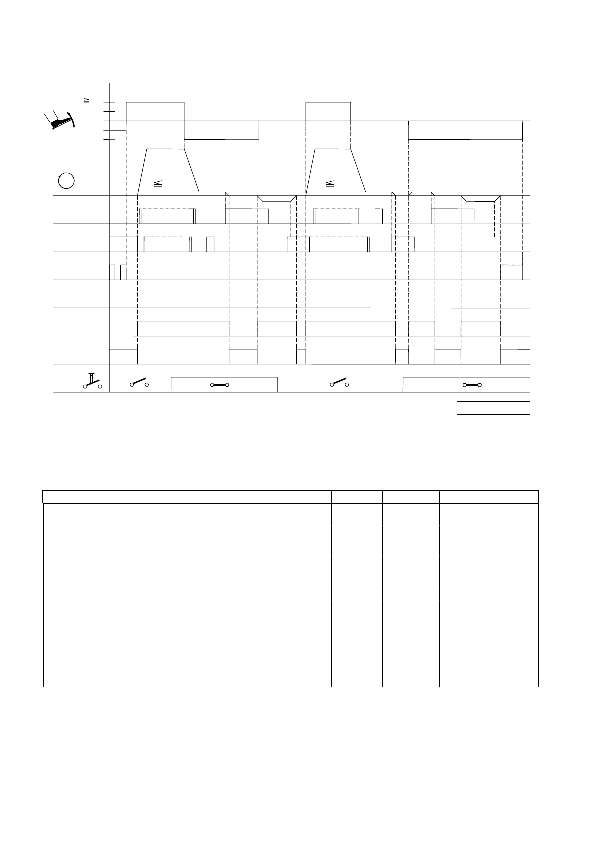
Mode 6 (chainstitch with fast scissors) parameter 232 = 1
1
/
2
1
-
0
-1
+
-2
37
EFKA AB320A5200
n
POS.1
ST2/20
POS.2
ST2/21
FL
ST2/35
STV
ST2/34
M1
ST2/37
M2
ST2/28
(AH 1 )
M3
ST2/27
(AH 2 )
M4
ST2/36
M5
(M L)
ST2/32
M6
(M S T)
ST2/
30
0 1n62 3
SSc
n3
t1t3 c1
kd3
kt3
n2 n7
kt4kd4
kdF
kd1 kt1
kd2
kd3
kt3
kt2
n3
0
1n62 3
SSc
t3
t1c1
n2 n7
kdF
kd1 kt1
kd2
kt2
kd4
kt4
AH
0256/M O DE- 6
Mark Function Parameter Control V810 V820
Mode 6 290 = 6
Softstart 134 = 1
Start stitch condensing On S2 key 1 key 1 key
Chainstitch with fast scissors M3/M4 232 = 1
n2 Maximum speed 111
n3 Start stitch condensing speed 112
n6 Softstart speed 115
n7 Trimming speed 116
t1 Delay until speed release after stitch condensing 200
t3 Start delay from lifted sewing foot 202
c1 Stitch counting of start stitch condensing 001
SSc Softstart stitches 100
kd1/kd2 Delay times of outputs M1/M2 280/282
kt1/kt2 ON periods of outputs M1/M2 281/283
kd3/kd4 Delay times of outputs M3/M4 (AH1/AH2) 284/286
kt3/kt4 ON periods of outputs M3/M4 (AH1/AH2) 285/287
kdF Switch-on delay of sewing foot lifting 288
Page 36
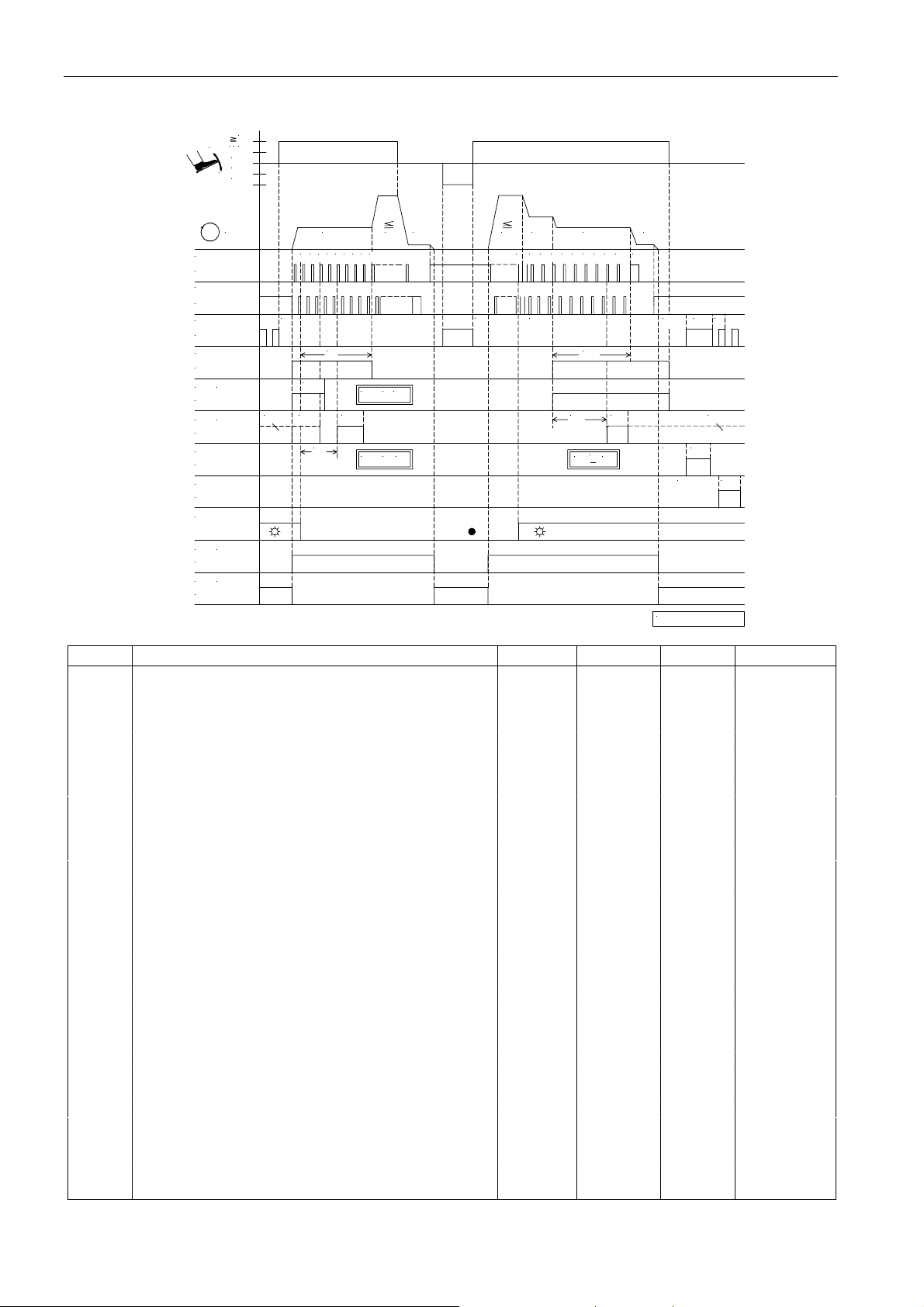
EFKA AB320A5200
38
Mode 7 (overlock) parameter 232 = 0 (tape cutter) / parameter 018 = 0 (seam end with stop)
1
1/2
-
0
-1
+
-2
POS.1
ST2/20
POS.2
ST2/21
FL
ST2/35
KS
ST2/34
(FS P L)M4
ST2/36
(AH )
M3
ST2/27
M1
ST2/37
M2
ST2/28
LS
(M L)
M5
ST2/32
(M S T)
M6
ST2/30
n
0
4321 5 6 7 8
t3
c1
SFS
ckLKLM kt3
c3
ckL
n2n3
n1 n7
<SFS
c1
<
c3
n2 n5
1 53 4n42 3 4 5 6 7
t3
LS
1
c2
c4 c2
t4kdF t5
kt3c4
<
0256/M ODE- 7a
KLM
kd1 kt1
kt2kd2
Mark Function Parameter Control V810 V820
Mode 7 290 = 7
Counts c1, c2, c3 and c4 On S2/3 key 1/2 key 1/4 key
Sewing foot lifting at the seam end On S4 key 3 key 6 key
Light barrier 009 = 1
Sequence “overlock mode with stop” 018 = 0
Function “pedal in pos. –2” blocked 019 = 2
Chain suction at the seam end until pedal in pos. 0 022 = 1
Start blockage with light barrier uncovered 132 = 0
Stitch counting at the start of the seam at fixed 143 = 0
speed n3
Stitch counting at the seam end at fixed speed n4 144 = 0
Seam end after count c2 191 = 1
Speed n5 after light barrier sensing 192 = 0
Chain suction On after light barrier compensating 193 = 0
stitches
Tape cutter function 232 = 0
n1 Positioning speed 110
n2 Maximum speed 111
n3 Speed for start counting 112
n4 Speed for end counting 113
n5 Speed after light barrier sensing 114
n7 Trimming speed 116
c2 End counting for chain suction 000
c1 Start counting for chain suction 001
c3 Start counting for tape cutter 002
c4 End counting for tape cutter 003
LS Light barrier compensating stitches 004
kLM Clamp at the seam end On 020 = 1
ckL Run-out stitches clamp at the start of the seam 021
kd1/kd2 Delay times of outputs M1/M2 280/282
kt1/kt2 ON periods of outputs M1/M2 281/283
kt3 ON period of tape cutter 285
kdF Switch-on delay of sewing foot lifting 288
Page 37
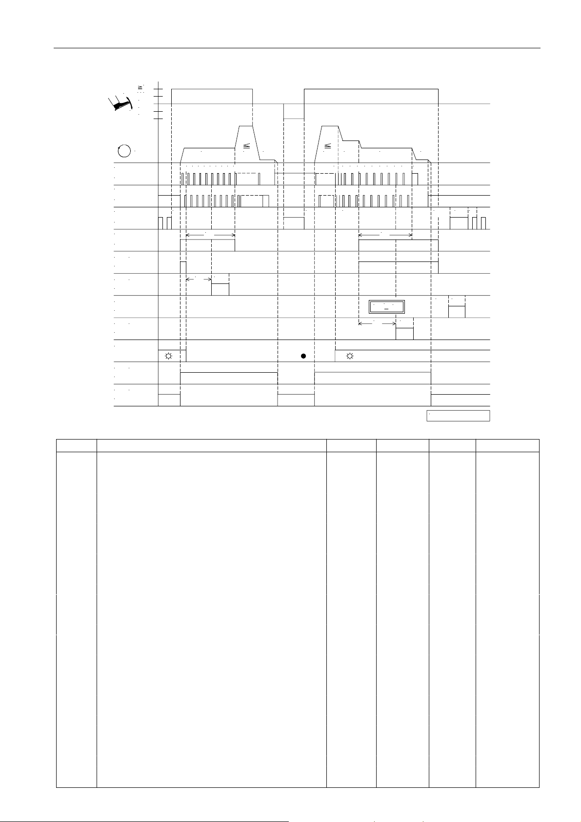
39
Mode 7 (overlock) parameter 232 = 1 (fast scissors) / parameter 018 = 0 (seam end with stop)
1
1/2
-
0
-1
+
-2
EFKA AB320A5200
n
POS.1
ST2/20
POS.2
ST2/21
FL
ST2/35
KS
ST2/34
M4
(FS P L)
ST2/36
M3
(AH 1 )
ST2/27
M1
ST2/37
M2
(AH 2 )
ST2/28
LS
M5 (M L)
ST2/32
M6
(M S T)
ST2/30
n2n3
n1
0
4321 5 6 7 8
t3
c1
kt3c3
n21n5
3 4 1n42 3 4 5 6 7
t3 LS
5
c2
<
c4 c2
c4
n7
t4kdF t5
kt1kd1
kt2
0256/M O DE- 7c
Mark Function Parameter Control V810 V820
Mode 7 290 = 7
Counts c1, c2, c3 and c4 On S2/3 key 1/2 key 1/4 key
Sewing foot lifting at the seam end On S4 key 3 key 6 key
Light barrier 009 = 1
Sequence “overlock mode with stop” 018 = 0
Function “pedal in pos. –2” blocked 019 = 2
Chain suction at the seam end until pedal in pos. 0 022 = 1
Start blockage with light barrier uncovered 132 = 0
Stitch counting at the start of the seam at fixed 143 = 0
speed n3
Stitch counting at the seam end at fixed speed n4 144 = 0
Seam end after count c2 191 = 1
Speed n5 after light barrier sensing 192 = 0
Chain suction On after light barrier compensating 193 = 0
stitches
Function “fast scissors” 232 = 1
n1 Positioning speed 110
n2 Maximum speed 111
n3 Speed for start counting 112
n4 Speed for end counting 113
n5 Speed after light barrier sensing 114
n7 Trimming speed 116
c2 End counting for chain suction 000
c1 Start counting for chain suction 001
c3 Start counting for tape cutter 002
c4 End counting for tape cutter 003
LS Light barrier compensating stitches 004
kLM Clamp at the seam end Off 020 = 0
kd1 Delay time of output M1 280
kd2 Delay time of output M2 282 = 0
kt1/kt2 ON periods of outputs M1/M2 281/283
kt3 ON period of tape cutter 285
kdF Switch-on delay of sewing foot lifting 288
Page 38
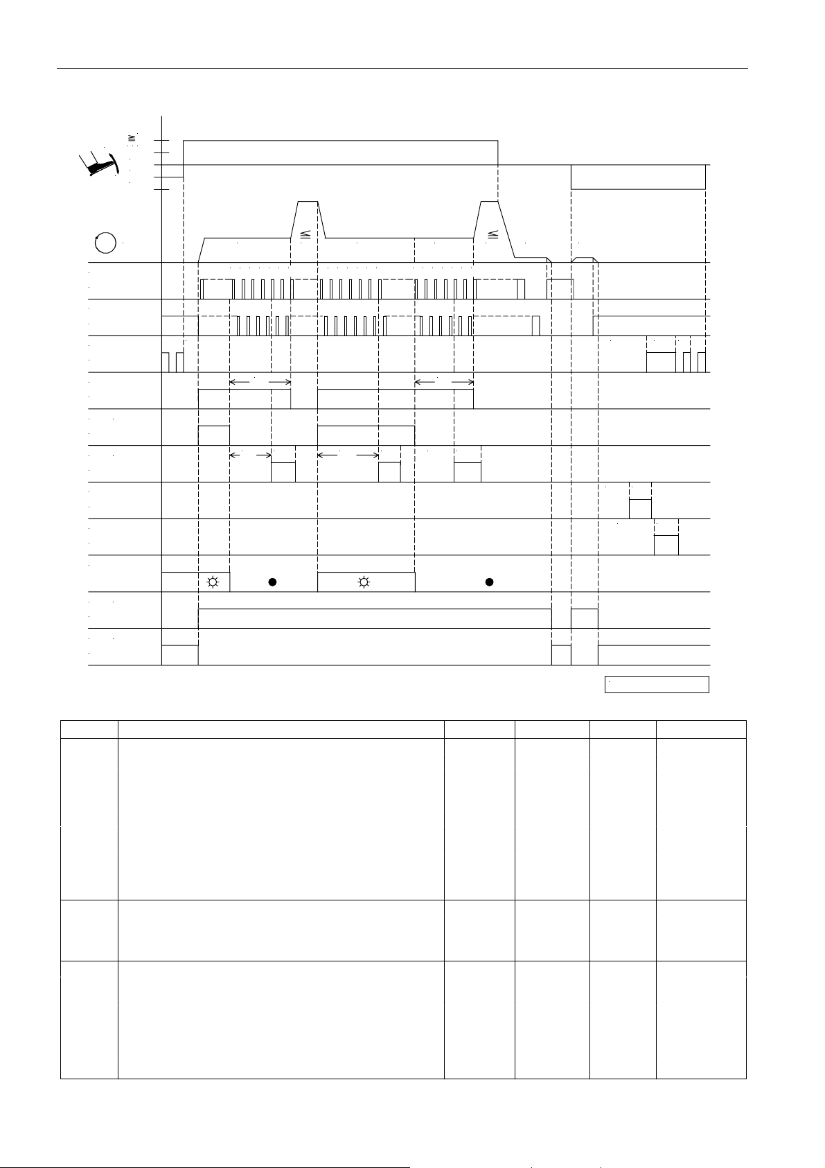
EFKA AB320A5200
40
Mode 7 (overlock) parameter 232 = 0 (tape cutter) / parameter 018 = 1 (seam end without stop)
1
1/2
-
0
-1
+
-2
POS.1
ST2/20
POS.2
ST2/21
FL
ST2/35
KS
ST2/34
(FS P L)
M4
ST2/36
(AH )
M3
ST2/27
M1
ST2/37
M2
ST2/28
LS
(M L)
M5
ST2/32
(M S T)
M6
ST2/30
n
t3
n3 n2
0 1 2 3 4 65
c1
kt3c3 kt3c4
n4
1 2 3 4 65 7
c1
kt3c3
50 1 2 3 4 6
n2n3
n1 n7
t4kdF t5
kd1 kt1
kd2 kt2
0256/M O DE- 7b
Mark Function Parameter Control V810 V820
Mode 7 290 = 7
Counts c1, c2, c3 and c4 On S2/3 key 1/2 key 1/4 key
Light barrier compensating stitches 004 = 0
Light barrier 009 = 1
Sequence “overlock mode at the seam end without stop” 018 = 1
Function “pedal in pos. –1/–2” activated in the seam 019 = 3
Chain suction at the seam end until pedal in pos. 0 022 = 1
Stitch counting at the start of the seam at fixed 143 = 0
speed n3
Stitch counting at the seam end at fixed speed n4 144 = 0
Tape cutter function 232 = 0
n1 Positioning speed 110
n2 Maximum speed 111
n3 Speed for start counting 112
n7 Trimming speed 116
t3 Start delay from lifted sewing foot 202
c1 Start counting for chain suction 001
c3 Start counting for tape cutter 002
c4 End counting for tape cutter 003
kd1/kd2 Delay times of outputs M1/M2 280/282
kt1/kt2 ON periods of outputs M1/M2 281/283
kt3 ON period of tape cutter 285
kdF Switch-on delay of sewing foot lifting 288
Page 39
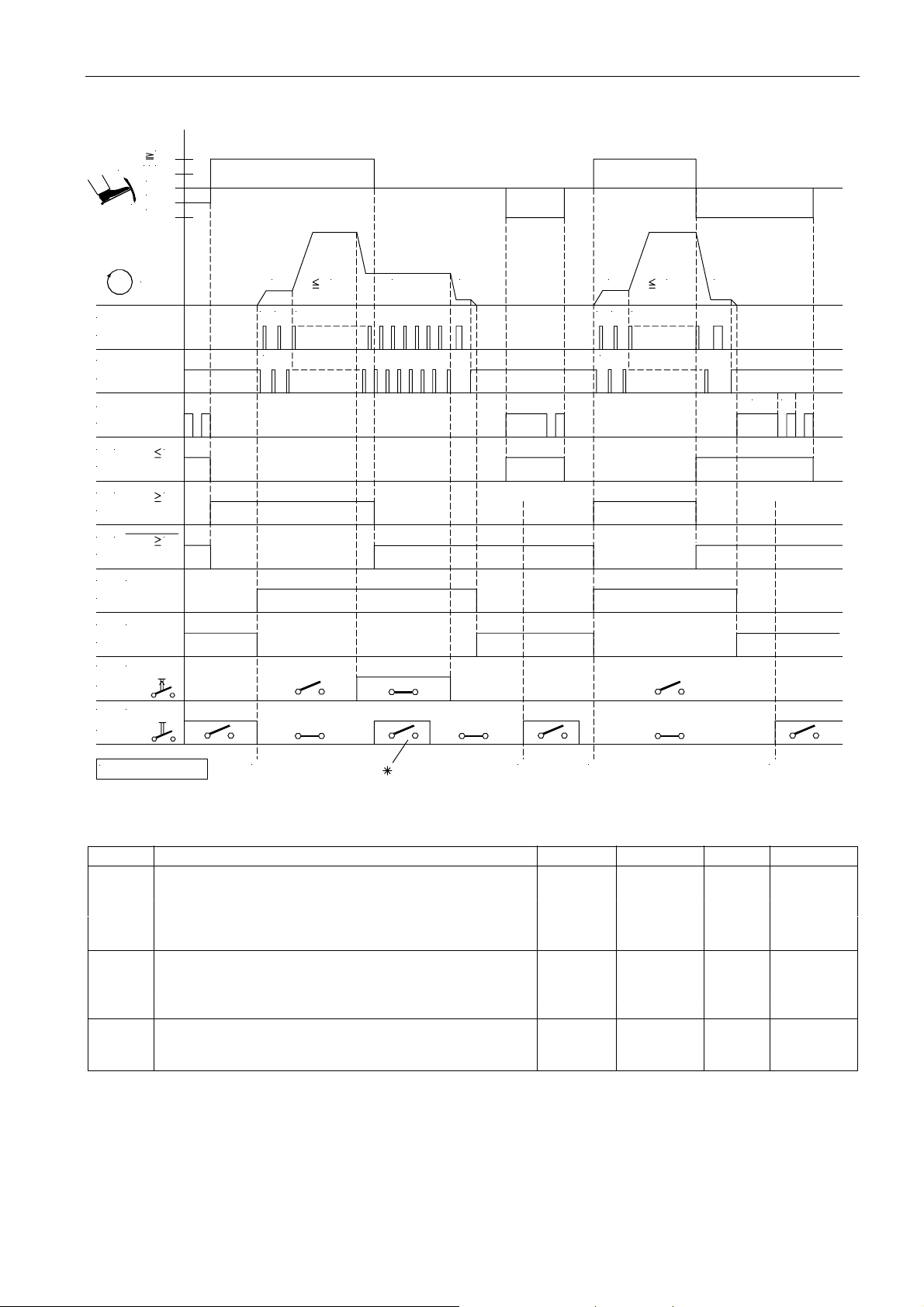
Mode 8 (backlatch Pegasus)
1
21/
-
0
-1
+
-2
41
EFKA AB320A5200
POS.1
ST2/20
POS.2
ST2/21
FL
ST2/35
/PED
M1
ST2/37
/PED
M2
ST2/28
/PED
M3
ST2/27
M5
(M L)
ST2/32
M6
(M S T)
ST2/30
in3
(n 1 2 )
ST2/6
(LS P )in1
ST2/7
n
-1
+1
+1
n6
SSc
n2 n1 2
20 1
n1
n6
0 1 2
SSc
n2
n1
t4 t5
0256/M O DE- 8
NA
NE NA NE
Mark Function Parameter Control V810 V820
Mode 8 290 = 8
Basic position 2 On S5 key 4 key 7 key
SSt Softstart 134 = 1
in1 Machine run blockage activated with open switch 240 = 6
in3 n-Auto with closed switch 242 = 10
n1 Positioning speed 110
n2 Maximum speed 111
n6 Softstart speed 115
n12 Automatic speed 118
t4 Full power of sewing foot lifting 203
t5 Pulsing of sewing foot lifting 204
SSc Softstart stitches 100
*) W hen automatic speed is On, machine run blockage (safety switch) does not work!
NA Start of seam
NE Seam end
Page 40
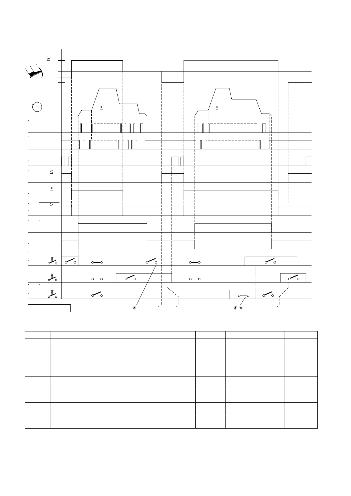
EFKA AB320A5200
Mode 9 (backlatch Yamato)
1
1/2
-
0
-1
+
-2
42
POS.1
ST2/20
POS.2
ST2/21
FL
ST2/35
/PED
M1
ST2/37
/PED
M2
ST2/28
/PED
M3
ST2/27
M5
(M L)
ST2/32
M6
(M S T)
ST2/30
(LS P )
in1
ST2/7
in3
(n 1 2 )
ST2/6
in4
(n 9 )
ST2/8
n
0
1n62
SSc
-1
+1
+1
n2 n1
n12
n9n2 n1
1n60 2
SSc
t3
0256/M O DE- 9
NE
NA NANE
Mark Function Parameter Control V810 V820
Mode 9 290 = 9
Basic position 2 On S5 key 4 key 7 key
SSt Softstart 134 = 1
in1 Machine run blockage activated with open switch 240 = 6
in3 Automatic speed with open switch 242 = 10
(the function of input 3 is inverted in mode 9)
n1 Positioning speed 110
n2 Maximum speed 111
n6 Softstart speed 115
n12 Automatic speed 118
t3 Start delay from lifted sewing foot 202
t4 Full power of sewing foot lifting 203
t5 Pulsing of sewing foot lifting 204
SSc Softstart stitches 100
*) With this setting, machine run blockage (safety switch) takes priority over automatic speed!
Page 41
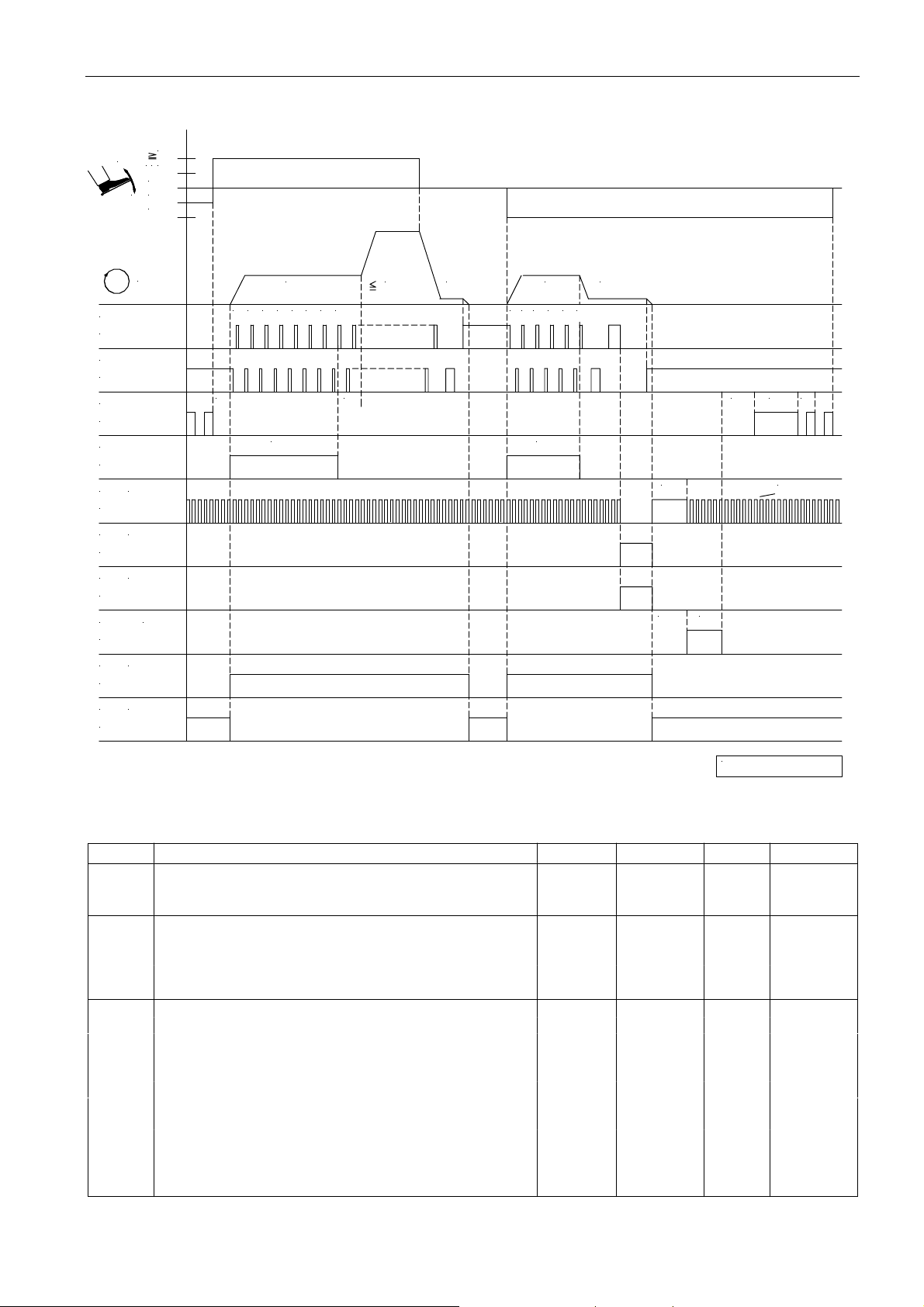
Mode 10 (lockstitch)
1
-
1/2
0
+
-1
-2
43
EFKA AB320A5200
n
POS.1
ST2/20
POS.2
ST2/21
FL
ST2/35
M4
ST2/36
(FA- R)
STV
ST2/34
(FS P L)
M1
ST2/37
(FA- V)
M2
ST2/28
M3
ST2/27
M5
(M L)
ST2/32
M6
(M S T)
ST2/30
(FW )
n3
0 1 2 3t34 5 6 7
c1
n2 n4
t1
n1
0 1 2 3 4 5
c3
n7
t7
t4 t5
t1 0 t1 1
t6dFw
0256/M O DE- 10
Mark Function Parameter Control V810 V820
Mode 10 290 = 10
Single start backtack On S2 key 1 key 1 key
Single end backtack On S3 key 2 key 4 key
n1 Positioning speed 110
n2 Maximum speed 111
n3 Start backtack speed 112
n4 End backtack speed 113
n7 Trimming speed 116
t1 Delay until speed release after start backtack 200
t3 Start delay from lifted sewing foot 202
t4 Full power of sewing foot lifting 203
t5 Pulsing of sewing foot lifting 204
t6 Thread wiper ON period 205
t7 Sewing foot switch-on delay after thread wiper 206
dFW Switch-on delay of the thread wiper 209
t10 Full power of thread trimmer backward 212
t11 Holding power output “stitch condensing” of the thread 213
trimmer backward
c1 Start backtack stitches backward 001
c3 End backtack stitches backward 002
Page 42
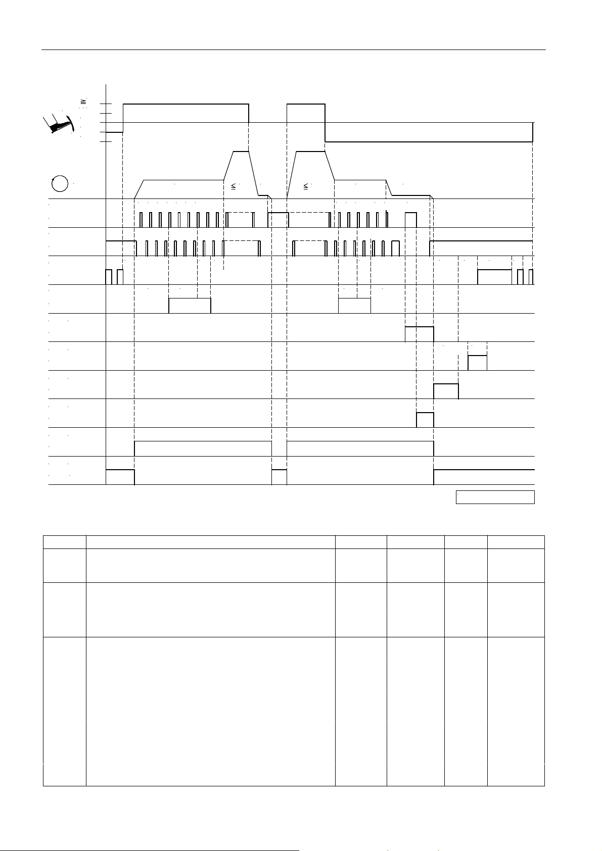
EFKA AB320A5200
Mode 14 (lockstitch)
1
/
21
-
0
-1
+
-2
44
n
POS.1
ST2/20
POS.2
ST2/21
FL
ST2/35
VR
ST2/34
(FA1+ 2)
M1
ST2/37
(FZ )
M2
ST2/28
(FW )
M3
ST2/27
(FA2)M4
ST2/36
(M L)
M5
ST2/32
(M S T)
M6
30
ST2/
310n32 3 1 2
t3 t1
c2
t8
c1
n2n1n2
0
1n42 1 2n73
t7
c3
t6t9
c4
kd4
t4 t5
kt4
0256/M O DE- 14
Mark Function Parameter Control V810 V820
Mode 14 290 = 14
Double start backtack with stitch correction On S2 key 1 key 1 key
Double end backtack with stitch correction On S3 key 2 key 4 key
n1 Positioning speed 110
n2 Maximum speed 111
n3 Start backtack speed 112
n4 End backtack speed 113
n7 Trimming speed 116
t1 Delay until speed release after start backtack 200
t3 Start delay from lifted sewing foot 202
t4 Full power of sewing foot lifting 203
t5 Pulsing of sewing foot lifting 204
t6 Thread wiper ON period 205
t7 Sewing foot switch-on delay after thread wiper 206
t8 Start backtack stitch correction 150
t9 End backtack stitch correction 151
c2 Start backtack stitches forward 000
c1 Start backtack stitches backward 001
c3 End backtack stitches backward 002
c4 End backtack stitches forward 003
kd4 Delay time output M2 286
kt4 ON period output M2 287
Page 43
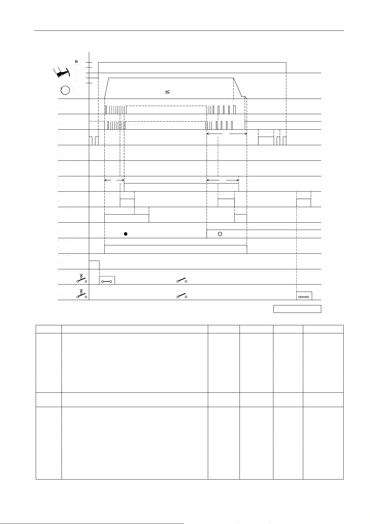
45
EFKA AB320A5200
Mode 15 (Pegasus SSC100) sequence when high lift for walking foot is Off / start of seam with light barrier covered
1
21/
-
0
-1
+
-2
n
POS.1
ST2/20
POS.2
ST2/21
FL
ST2/35
(K B )M1
ST2/37
(K S )
M2
ST2/28
(FS P L)
M3
ST2/27
(AH )
M4
ST2/36
(K S )
VR
ST2/34
t3
c1
c7 kt4
kt6
n2
31 4 5 6 7
c2
c8 kt4
n1
t5LS t4kdF
kt4
LS
(M L)
M5
ST2/32
(H P )M6
ST2/30
(H P )in4
ST2/8
(AH )
in5
ST2/5
0256/MODE- 15a
Mark Function Parameter Control V810 V820
Mode 15 290 = 15
Tape cutting On 2 key 4 key
Counts c1 and c2 On S2/3 key 1 key 1/5 key
Basic position 2 On S5 key 4 key 7 key
Light barrier 009 = 1
Speed of the light barrier compensating stitches 192 = 1
depending on the pedal
in4 Key for high lift for walking foot operational mode stored 243 = 14
in5 Key for manual tape cutter 244 = 15
n1 Positioning speed 110
n2 Maximum speed 111
c2 Stitch counting until thread tension release Off 000
c1 Stitch counting until thread tension release On 001
LS Light barrier compensating stitches 004
t3 Start delay from lifted sewing foot 202
t4 Full power of sewing foot lifting 203
t5 Pulsing of sewing foot lifting 204
kdF Delay time until sewing foot lifting On 288
kt6 *) Delay time of output VR (chain suction) 256
c7 Start counting until tape cutter M4 On 257
c8 End counting until tape cutter M4 On 258
kt4 *) ON period of tape cutter M4 287
*) The value displayed on the control unit must be multiplied by 10. Example: The displayed value 10
corresponds to 100ms.
Page 44
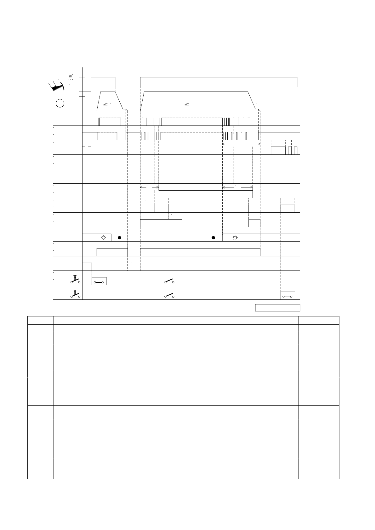
EFKA AB320A5200
46
Mode 15 (Pegasus SSC100) sequence when high lift for walking foot is Off / start of seam with light barrier
uncovered
1
21/
-
0
-1
+
-2
POS.1
ST2/20
POS.2
ST2/21
FL
ST2/35
M1
(K B )
ST2/37
M2
(K S )
ST2/28
M3
(FS P L)
ST2/27
M4
(AH )
ST2/36
VR
(K S )
ST2/34
n
t3
n1n2 n1
c1
c7 kt4
kt6
n2
31 4 5 6 7
LS
c2
kt4c8
t5t4kdF
kt4
LS
M5
(M L)
ST2/32
M6
(H P )
ST2/30
in4
(H P )
ST2/8
in5
(AH )
ST2/5
**)
0256/M OD E- 15c
Mark Function Parameter Control V810 V820
Mode 15 290 = 15
Tape cutting On 2 key 4 key
Counts c1 and c2 On S2/3 key 1 key 1/5 key
Basic position 2 On S5 key 4 key 7 key
Light barrier 009 = 1
Speed of the light barrier compensating stitches 192 = 1
depending on the pedal
in4 Key for high lift for walking foot operational mode stored 243 = 14
(M6 inverted)
in5 Key for manual tape cutter 244 = 15
n1 Positioning speed 110
n2 Maximum speed 111
c2 Stitch counting until thread tension release Off 000
c1 Stitch counting until thread tension release On 001
LS Light barrier compensating stitches 004
t3 Start delay from lifted sewing foot 202
t4 Full power of sewing foot lifting 203
t5 Pulsing of sewing foot lifting 204
kdF Delay time until sewing foot lifting On 288
kt6 *) Delay time of output VR (chain suction) 256
c7 Start counting until tape cutter M4 On 257
c8 End counting until tape cutter M4 On 258
kt4 *) ON period of tape cutter M4 287
*) The value displayed on the control unit must be multiplied by 10. Example: The displayed value 10
corresponds to 100ms.
**) Programming is possible at intermediate stop before tape cutting at the start of the sea m!
Page 45
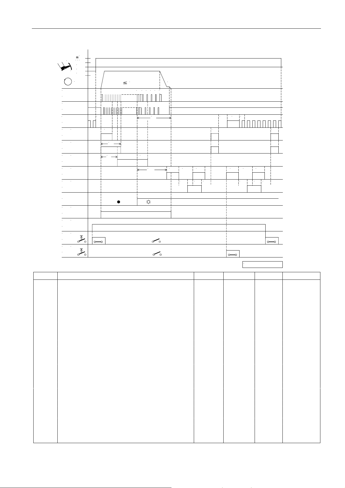
47
Mode 15 (Pegasus SSC100) sequence when high lift for walking foot is On
1
21/
-
0
-1
+
-2
n
POS.1
ST2/20
POS.2
ST2/21
FL
ST2/35
(K B )
M1
ST2/37
(K S )
M2
ST2/28
(FS P L)
M3 c1
ST2/27
(AH )
M4
ST2/36
(K S + K B )
VR
ST2/34
t3
c4
3n21 4 5 6 7
c3
c2
n1
LS
kt1
kd4
kt4ckL
kt4 kt4
kd2
t5kdF t4
kd4 kt4
kd2kt2 kd1
EFKA AB320A5200
kt1
kd1kt2
LS
(M L)
M5
ST2/32
(H P )
M6
ST2/30
(H P )
in4
ST2/8
(AH )
in5
ST2/5
0256/M O D E- 15b
Mark Function Parameter Control V810 V820
Mode 15 290 = 15
Tape cutting On 2 key 4 key
Counts c1 and c2 On S2/3 key 1 key 1/5 key
Basic position 2 On S5 key 4 key 7 key
Light barrier 009 = 1
Speed of the light barrier compensating stitches 192 = 1
depending on the pedal
in4 Key for high lift for walking foot operational mode stored 243 = 14
in5 Key for manual tape cutter 244 = 15
n1 Positioning speed 110
n2 Maximum speed 111
c2 Stitch counting until thread tension release Off 000
c1 Stitch counting until thread tension release On 001
c3 Counting for chain suction 002
c4 Counting for chain blowing 003
LS Light barrier compensating stitches 004
ckL Counting after light barrier uncovered until tape cutter On 021
t3 Start delay from lifted sewing foot 202
t4 Full power of sewing foot lifting 203
t5 Pulsing of sewing foot lifting 204
kdF Delay time until sewing foot lifting On 288
kd1 *) Delay time of output M1 and M2 280
kt1 *) ON period of output M1 and M2 281
kd2 *) Delay time of output ST2/34 282
kt2 *) ON period of output ST2/34 283
kd4 *) Delay time of output M4 (tape cutter) 286
kt4 *) ON period of tape cutter M4 (tape cutter) 287
*) The value displayed on the control unit must be multiplied by 10. Example: The displayed value 10
corresponds to 100ms.
Page 46
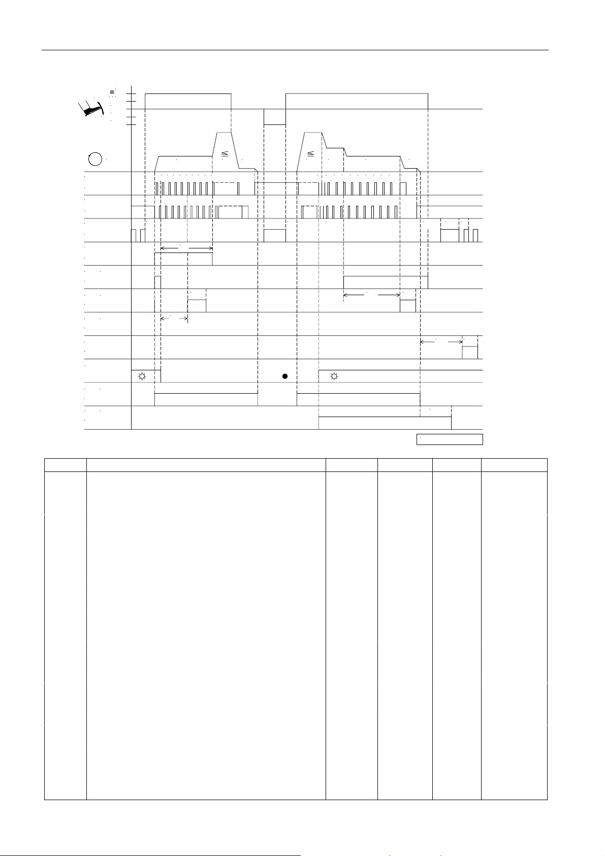
EFKA AB320A5200
48
Mode 16 (feed-off-the-arm machine) without automatically unlocking the chain with tape cutter (232 = 0)
1
/
1
2
-
0
-1
+
-2
n
POS.1
ST2/20
POS.2
ST2/21
FL
ST2/35
KS
ST2/34
(FS P L)
M4
ST2/36
M3 (AH )
ST2/27
M1 (R B )
ST2/37
M2
ST2/28
LS
M5 (M L)
ST2/32
(S TB )
M7
ST2/23
n3
2
0 1
43 5 6 7 8
t3
c1
kt3
c3
n2 n1
n2 n5
1 3 4 15 7
t3
LS
n4
2
3 4 5 6
c4 kt3
n7
kdF t5t4
kd2 kt2
kt5
0256/M OD E- 16
Mark Function Parameter Control V810 V820
Mode 16 290 = 16
Counts c1, c3 and c4 On S2/3 key *) 1/2/4 key
Basic position 2 On S5 key *) 0 key
Sewing foot lifting at the seam end On S4 key *) 9 key
Light barrier 009 = 1
Sequence “overlock mode with stop” 018 = 0
Function “pedal in pos. –2” blocked 019 = 2
Start blockage with light barrier uncovered 132 = 0
Stitch counting at the start of the seam at fixed 143 = 0
speed n3
Stitch counting at the seam end at fixed speed n4 144 = 0
Seam end after count c2 191 = 0
Speed of the light barrier compensating stitches 192 = 0
depending on the pedal
Blow fabric onto stack M7 from light barrier uncovered 194 = 1
onwards
n1 Positioning speed 110
n2 Maximum speed 111
n3 Speed for start counting 112
n4 Speed for end counting 113
n5 Speed after light barrier sensing 114
n7 Trimming speed 116
c1 Start counting for chain suction 001
c3 Start counting for tape cutter 002
c4 End counting for tape cutter 003
LS Light barrier compensating stitches 004
kd2 Delay time of output M2 282
kt2 ON period of output M2 283
kt3 ON period of tape cutter 285
kdF Switch-on delay until sewing foot lifting On 288
kt5 Switch-off delay “blow fabric onto stack at the seam end” 289
*) The V810 control panel cannot be used for the functions in mode 16!
Page 47
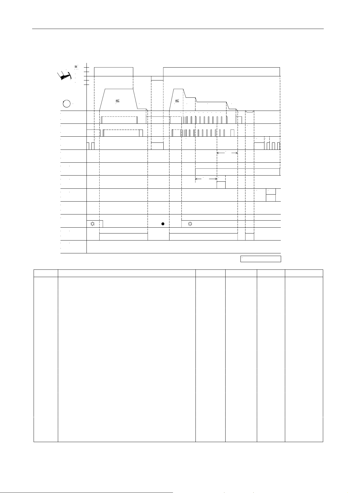
49
EFKA AB320A5200
Mode 16 (feed-off-the-arm machine) automatically unlocking the chain with tape cutting / 8 key on V820
On
1
1/2
-
0
-1
+
-2
n
POS.1
ST2/20
POS.2
ST2/21
FL
ST2/35
KS
ST2/34
M4
(FS P L)
ST2/36
M3
(AH )
ST2/27
M1
(R B )
ST2/37
M2
ST2/28
LS
M5 (M L)
ST2/32
M7 (S TB )
ST2/23
n1n2
t3
n2
1 3 4 15 2n74 5 321
t3 LS
n5
n4
3
c4 kt3
drd
c6
ird
t4 t5
kt1kd1
0256/ M O DE- 16a
Mark Function Parameter Control V810 V820
Mode 16 290 = 16
Counts c4 On S2/3 key *) 1/2/4 key
Basic position 1 On S5 key *) 0 key
Unlock the chain with chain blowing in opposite On *) 8 key
direction
Light barrier 009 = 1
Sequence “overlock mode with stop” 018 = 0
Function “pedal in pos. –2” blocked 019 = 2
Start blockage with light barrier uncovered 132 = 0
Stitch counting at the seam end at fixed speed n3 143 = 0
Stitch counting at the seam end at fixed speed n4 144 = 0
Speed n5 after light barrier sensing 192 = 0
Blow fabric onto stack M7 from light barrier uncovered 194 = 1
onwards
n1 Positioning speed 110
n2 Maximum speed 111
n3 Speed for start counting 112
n4 Speed for end counting 113
n5 Speed after light barrier sensing 114
n7 Trimming speed 116
c4 End counting for tape cutter 003
LS Light barrier compensating stitches 004
ird Number of reversing increments 180
drd Switch-on delay of reverse motor rotation 181
c6 N umber of run-out stitch es w hen unlo ck ing the cha in 184
kd1 Delay time of output M1 280
kt1 ON period of output M1 281
*) The V810 control panel cannot be used for the functions in mode 16!
Page 48
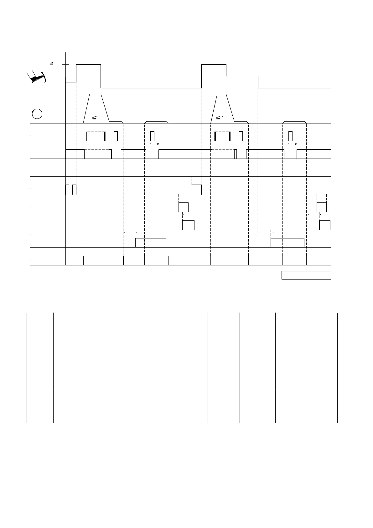
EFKA AB320A5200
Mode 17 (stitch lock Pegasus)
1
/
2+1
-
0
-1
-2
50
n
POS.1
ST2/20
POS.2
ST2/21
FL
ST2/35
VR
(LFA)
ST2/34
M2
(FA)
ST2/28
M3
(S TS )
ST2/27
ML
ST2/32
n2 n7 n7
t3
kd3 kt3
dr
kd1
kd2
kdF
kt1
kt2
n2 n1
t3
kd3
n7
dr
kt3
0256/M O DE- 17
kd1
kd2
kt1
kt2
Mark Function Parameter Control V810 V820
Mode 17 290 = 17
Basic position 2 On S5 key 4 key 7 key
Thread trimmer and thread wiper On S3 key 5 key
n1 Positioning speed 110
n2 Maximum speed 111
n7 Trimming speed 116
dr° Stop for thread trimming depending on angle 197
t3 Start delay from lifted sewing foot 202
kd1 Delay time of the top cover thread cutter LFA 280
kt1 ON period of the top cover thread cutter LFA 281
kd2 Delay time of the thread trimmer FA 282
kt2 ON period of the thread trimmer FA 283
kd3 Delay time of the stitch lock function STS 284
kt3 ON period of the stitch lock function STS 285
kdF Switch-on delay until sewing foot lifting On 288
Page 49
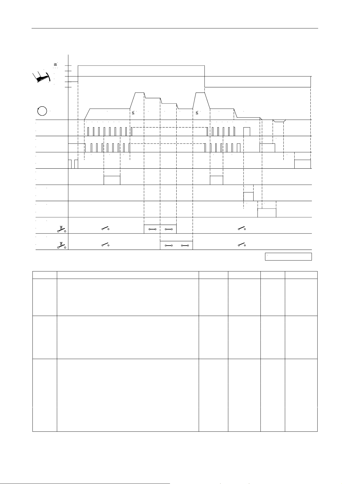
Mode 20 (lockstitch Juki LU1510-7)
1
/
21
-
0
-1
+
-2
51
EFKA AB320A5200
n
POS.1
ST2/20
POS.2
ST2/21
FL
ST2/35
VR
ST2/34
M1
(FA)
ST2/37
M2
(FS P L)
ST2/28
in3
(B I T0)
ST2/6
in4
(B I T1)
ST2/8
0
t3
n3 n2 n11 n9
11 2 3 2 3
c2 t1c1
n2n10
1
0 2 21
c3
c4
n7n4
3
iFA
FSE
drd ird
t7
FSA
0256/M O DE- 20
Mark Function Parameter Control V810 V820
Mode 20 290 = 20
Double start backtack On S2 key 1 key 1 key
Double end backtack On S3 key 2 key 4 key
Reverse motor rotation 182 = 1
in3 Speed limitation bit 0 242 = 31
in4 Speed limitation bit 1 243 = 32
n2 Maximum speed 111
n3 Start backtack speed 112
n4 End backtack speed 113
n7 Trimming speed 116
n9 Automatic speed 122
n10 Automatic speed 117
n11 Automatic speed 123
t1 Delay until speed release after start backtack 200
t3 Start delay from lifted sewing foot 202
t7 Sewing foot switch-on delay after thread wiper 206
ird Number of reversing increments 180
drd Switch-on delay of reverse motor rotation 181
iFA Activation angle of the thread trimmer 250
FSA Thread tension release ON period 251
FSE Thread tension release delay depending on angle 252
c2 Start backtack stitches forward 000
c1 Start backtack stitches backward 001
c3 End backtack stitches backward 002
c4 End backtack stitches forward 003
Page 50
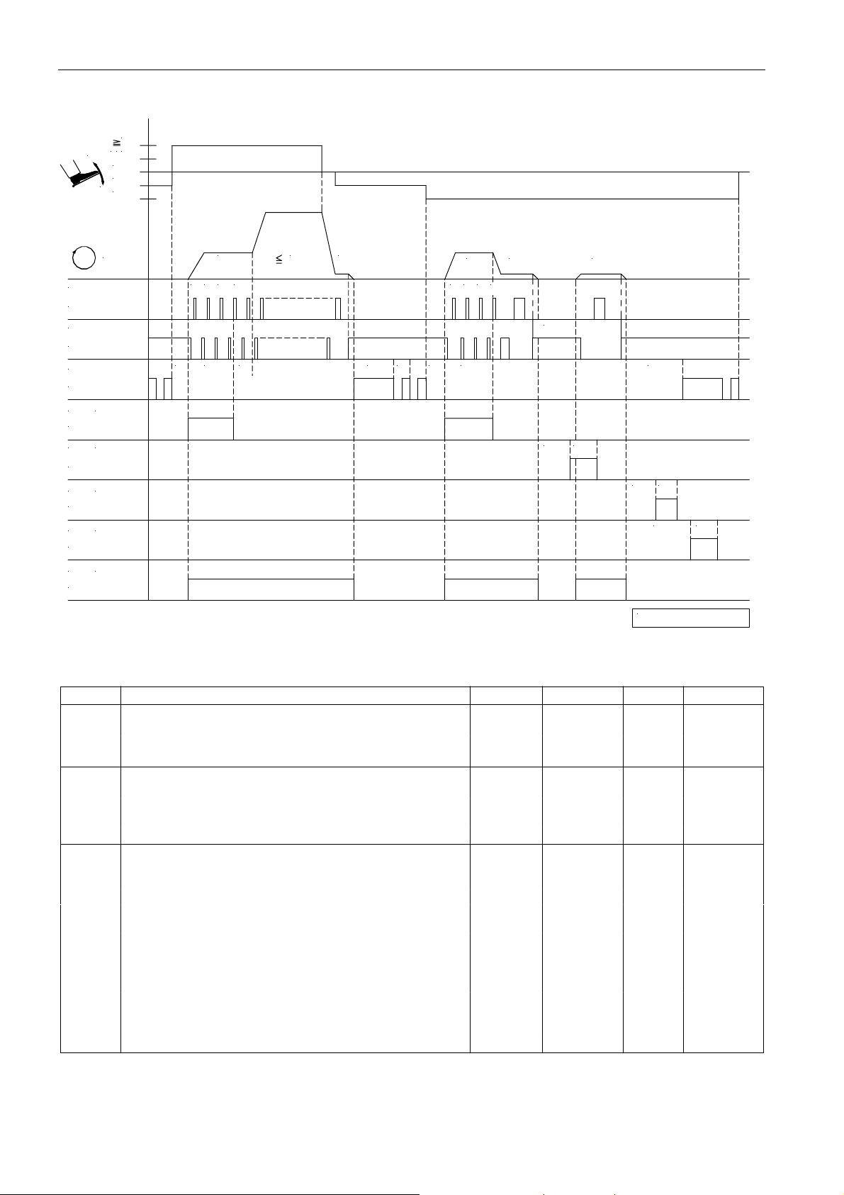
EFKA AB320A5200
Mode 21 (stitch lock)
1
/
21
-
0
-1
+
-2
52
n
POS.1
ST2/20
POS.2
ST2/21
FL
ST2/35
(S TV )
M2
ST2/28
(S TS )
STV
ST2/34
(FA)
M1
ST2/37
(FW )
M3
ST2/27
(M L)
M5
ST2/32
0 1t132
c1t3
n2n3 n1
t4 t5 t3
n4 n7 n7
1
0
32
tF A
c3
kdF
kt2kd2
kd1
kt1
kd3 kt3
0256/M O DE- 21
Mark Function Parameter Control V810 V820
Mode 21 290 = 21
Stitch lock function 196 = 1
Start stitch condensing On S2 key 1 key 1 key
End stitch condensing On S3 key 2 key 4 key
n1 Positioning speed 110
n2 Maximum speed 111
n3 Speed for start stitch condensing 112
n4 Speed for end stitch condensing 113
n7 Trimming speed 116
t1 Delay until speed release after stitch condensing 200
t3 Start delay from lifted sewing foot 202
t4 Full power of sewing foot lifting 203
t5 Pulsing of sewing foot lifting 204
tFA Stop time for drive 253
kd1 Delay time thread trimmer 280
kt1 ON period thread trimmer 281
kd2 Delay time stitch lock 282
kt2 ON period stitch lock 283
kd3 Delay time thread wiper 284
kt3 ON period thread wiper 285
kdF Switch-on delay until sewing foot lifting On 288
c1 Counting start stitch condensing 001
c3 Counting end stitch condensing 002
Page 51
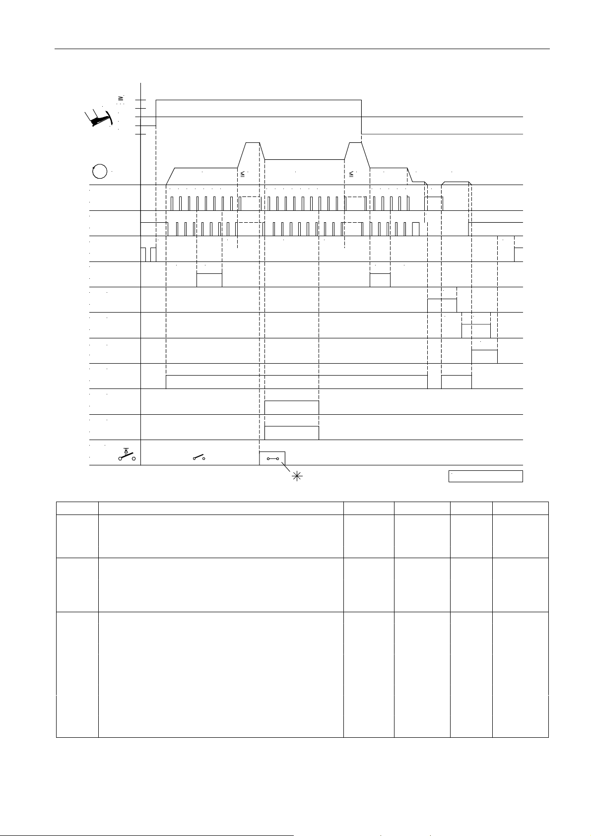
Mode 23 (lockstitch)
1
/ 021
-
-1
+
-2
53
EFKA AB320A5200
n
POS.1
ST2/20
POS.2
ST2/21
FL
ST2/35
VR
ST2/34
(FA )
M1
ST2/37
(FS P L)M4
ST2/36
(FW )
M3
ST2/27
(M L)
M2
ST2/28
(H P )M5
ST2/32
M11(LH P )
ST2/31
(H P )in1
ST2/7
10n32 3 1 2 3
t3 t1
c2 c1
n2
654321
7
cHP tH P
n2n10
0 1 2n41 2
c3
c4
n7
n7
3
tF A
iFA
FSE
0256/ M O D E- 23
t7
FSA
t6
Mark Function Parameter Control V810 V820
Mode 23 290 = 23
Double start backtack On S2 key 1 key 1 key
Double end backtack On S3 key 2 key 4 key
High lift for walking foot 137 = 1
n2 Maximum speed 111
n3 Start backtack speed 112
n4 End backtack speed 113
n7 Trimming speed 116
n10 High lift walking speed 117
t6 Thread wiper ON period 205
t7 Sewing foot switch-on delay after thread wiper 206
iFA Activation angle of the thread trimmer 250
FSA Thread tension release ON period 251
FSE Thread tension release delay depending on angle 252
tFA Stop time for thread trimmer 253
c2 Start backtack stitches forward 000
c1 Start backtack stitches backward 001
c3 End backtack stitches backward 002
c4 End backtack stitches forward 003
tHP High lift walking speed run-out time 152
cHP Stitch counting high lift for walking foot 185
*) If the key is pressed do wn longer than the cHP count, high lift for walking foot remains On as well. If the key
is pressed briefly, high lift for walking foot is On during counting, as shown in the timing diagram.
Page 52
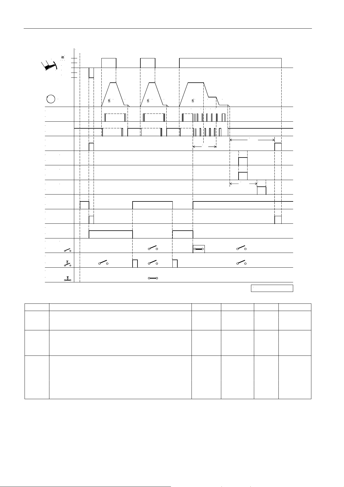
EFKA AB320A5200
54
Mode 24 (Pegasus MHG-100) “bottom hemming“ On
Power on
1
-
1/2
0
+
-1
-2
n
POS.1
ST2/20
POS.2
ST2/21
FL
ST2/35
(FA )
ST2/37
M2M1(FA )
ST2/28
M3 (FW )
ST2/27
M7
ST2/23
M8
ST2/24
M9
ST2/25
in3 (S E N )
ST2/6
in4
ST2/8
in2
ST2/11
n2 n1 n2 n1
dnL
n5n2
5
30 4 6
LS
n7
kdF
kt2kd2
kd3
kt3
0256/M O DE- 24
Mark Function Parameter Control V810 V820
Mode 24 290 = 24
Basic position 2 On S5 key 4 key 7 key
Light barrier 009 = 1
n1 Positioning speed 110
n2 Maximum speed 111
n5 Light barrier speed 114
n7 Trimming speed 116
LS Light barrier compensating stitches 004
dnL Delay time until light barrier speed release 158
kd2 Delay time of the thread trimmer M1 and M2 282
kt2 ON period of the thread trimmer M1 and M2 283
kd3 Delay time of the thread wiper M3 284
kt3 ON period of the thread wiper M3 285
kdF Switch-on delay until sewing foot On 288
Outputs: Inputs:
FL = Sewing foot lifting in1 = Machine run blockage Pa. 240= 6
M1/M2 = Thread trimmer in2 = Switch bottom/sleeve hemming Pa. 241=13
M3 = Thread wiper in3 = Sensor input Pa. 242=28
M7 = Hemming guide in4 = Knee switch “hemming guide” Pa. 243=22
M8 = Hemming blow 1
M9 = Hemming blow 2
M6 = Display “bottom/sleeve hemming”
Page 53
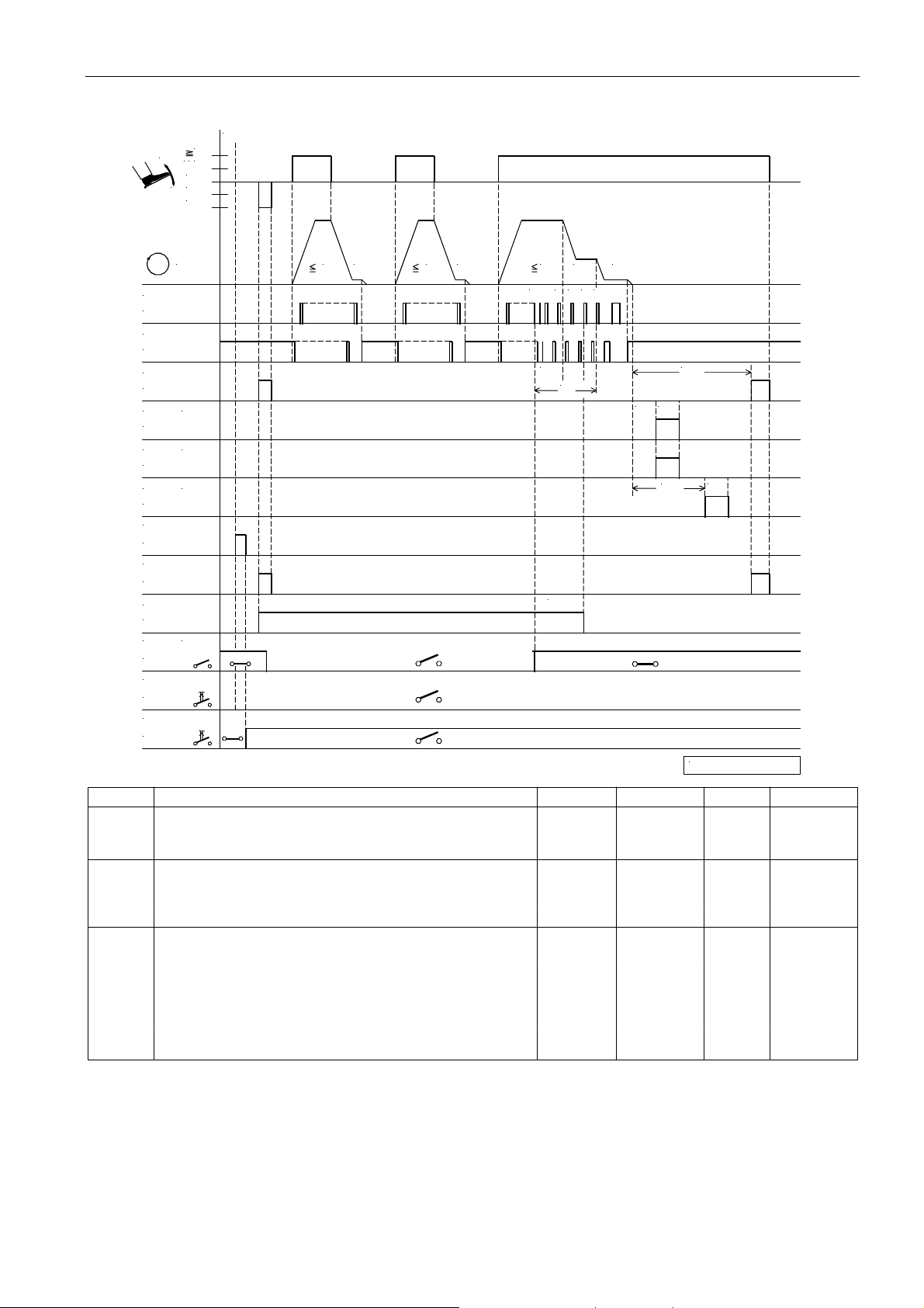
Mode 24 (Pegasus MHG-100) “sleeve hemming“ On
Power on
1
-
1/2
0
+
-1
-2
55
EFKA AB320A5200
n
POS.1
ST2/20
POS.2
ST2/21
FL
ST2/35
M1
ST2/37
M2
ST2/28
M3
ST2/27
M7
ST2/23
M8
ST2/24
M9
ST2/25
ST2/6
in4
ST2/8
in2
ST2/11
(FA)
(FA)
(FW )
(S EN )in3
n2 n1 n1n2
30 4n76
dnL
cb2
LS
n5n2
5
kdF
kd2 kt2
kd3
kt3
0256/M O DE- 24a
Mark Function Parameter Control V810 V820
Mode 24 290 = 24
Basic position 2 On S5 key 4 key 7 key
Light barrier 009 = 1
n1 Positioning speed 110
n2 Maximum speed 111
n5 Light barrier speed 114
n7 Trimming speed 116
LS Light barrier compensating stitches 004
dnL Delay time until light barrier speed release 158
cb2 Stitches until signal M9 “hemming blow 2” Off 159
kd2 Delay time of the thread trimmer M1 and M2 282
kt2 ON period of the thread trimmer M1 and M2 283
kd3 Delay time of the thread wiper M3 284
kt3 ON period of the thread wiper M3 285
kdF Switch-on delay until sewing foot On 288
Outputs: Inputs:
FL = Sewing foot lifting in1 = Machine run blockage Pa. 240= 6
M1/M2 = Thread trimmer in2 = Switch bottom/sleeve hemming Pa. 241=13
M3 = Thread wiper in3 = Sensor input Pa. 242=28
M7 = Hemming guide in4 = Knee switch “hemming guide” Pa. 243=22
M8 = Hemming blow 1
M9 = Hemming blow 2
M6 = Display “bottom/sleeve hemming”
Page 54

EFKA AB320A5200
56
6 List of Parameters
6.1 Preset Values Depending on Mode
The preset values which are different in the various modes are listed in the table below. When switching the mode b y
means of parameter 290, these values change automatically.
Operator Level
Mode !!!!0 2 3 4 5 6 7 8 9101415161720212324
Parameter
000 - ----------630----001 - - - 2 - - - - - 2 - 2 17 - - - - 002 - ----------102---3003 - ----------1018---3004 - -----0----250----35
005 - --0------------0007 - ---------------10008 - -----4---------2009 - -----1----11----1
013 - ------00--0-----014 - 0----000--00-0-0019 - -----2----221---3
021 - ----------23------
Technician Level
Mode !!!! 0 2 3 4 5 6 7 8 9101415161720212324
Parameter
100 - --------1-------** 110 - - - 180 - - - 250 250 180 - - - - - - 180 ** 111 - - - 5000 - - - - - 4500 - 7500 3800 - 2500 5500 4800 5000
** 112 - - - - - - - - - - - - 3800 - 600 - 1700 ** 113 - - - - - - - - - - - - 3800 - 600 - 1700 **114 - ---------------1700 2000
** 115 - - - - - - - - - 700 - - - - - - 800 **116 - ---------------180** 117 - - - - - - - - - - - 9900 - - 1800 - 2000 9900
**118 - -------------2500 - 3000 -
119 - -----------1---** 122 - - - - - - - - 6000 ---------
**123 - -------------2400 - - 9900
130 - -----1-----1-----
131 - ----------1------
132 - -----0----00----0
134 - - - - - - - - -1 - - - -1 -1 -
135 - -------------1---
137 - --------------111
152 - ---------------100-
153 - ---------0-----06-
158 - ----------------100
161 - --0000000-000-0 -0
180 - --------14----45-14-
181 - - - - - - - - - 230 - - - - - - 0 -
182 - -----1--1--1-1---
184 - -----------------
190 - --0--2-----1-----
192 - -----1----11-----
194 - -----------1-----
196 - ---------------0-
197 - ------------360----
x = The positions marked with ”x“ are not used in the functional sequence!
- = For the po sitions marked with “-“ the preset values listed in the List of Parameters are used !
** = When programming the 3-digit or 4-digit control parameter values (without control panel), the 2-digit or 3-digit
value displayed must be multiplied by 10.
Page 55
57
EFKA AB320A5200
Supplier Level
Mode !!!! 0 2 3 4 5 6 7 8 9101415161720212324
Parameter
200 - ---------------50201 - --160-----------200-202 - ------00-------80203 - --350------------200204 - --------12--------
** 205 - - - - - - - - - 240 - - - - - - 100 -
206 - - - - - - - - - 150 - - - - - - 50 207 - ---------------10209 - - - - - - - - - 100 - - - - - - - -
210 - ---------------100211 - ---------------0212 - - - 100 - - - - - 100 - - - - - - - 213 - --------12-100----50234 - ------00---------
240 - - - 6 - - - 6 6 - - - 15 - 13 - 13 6
241 - - - - - - - - - - 16 - - - - - 07 14
242 - --3---1038-----31-0128
243 - - - - - - - 1 34 - - 14 15 - 32 - 0 22
244 - ----------15----16-
245 - ------1212-----16-0246 - -------------13-33247 - ---------------11248 - --------------1428249 - ---------------17-
250 - ---------------400-
**253 - -------------0-0-
255 - --25-----25-------260 - --------------100--
262 - --------------20-269 - -------25--------270 - -------1-3----1-271 - - - - - - - - - - 200 - - - - 4 - -
272 - ----------------**274 - -----------0----** 275 - - - - - - - - - - - - 100 - - - - ** 280 x x x 100 - - 100 x x x - 10 - 100 - x - 100
** 281 - - - - - - - - - 280 - 50 1000 - - 250 - -
** 282 x 0 x 0 - - 200 x x x x 30 200 - - 40 - ** 283 - - - 200 - - - - - - - 100 - - - 80 - ** 284 x x x - - 0 0 x x 150 x - 0 - - 300 - 230
** 285 x x x - - - - x x 70 x - - 70 - 680 - ** 286 x x x x - 0 0 x x x x 100 0 - - - - -
** 287 x x x x - - 0 x x x x 50 0 - - - 0 ** 288 x x x - - - - x x x x - - 200 - - - -
291 - -- -55877- -775 -5 -5
292 - -- -33555- -573 -3 -3
293 - -----------------
294 - ----------14------
Further Functions Switchable by M eans of the Control Keys
Mode !!!! 0 2 3 4 5 6 7 8 9101415161720212324
Basic pos.1 11122222112221112
Single OFF OFF OFF ON ON ON ON OFF OFF OFF OFF ON ON OFF OFF OFF OFF OFF
start
backtack
Double ON ON ON OFF OFF OFF ON OFF OFF ON ON ON OFF OFF ON ON ON OFF
start
backtack
Single OFF OFF OFF ON ON ON ON OFF OFF OFF OFF ON ON OFF OFF OFF OFF OFF
end
backtack
Double ON ON ON OFF OFF OFF ON OFF OFF ON ON ON OFF OFF ON ON ON OFF
end
backtack
Note
The preset values of the following list of parameters refer to the setting of parameter 290 = 0.
x = The positions marked with ”x“ are not used in the functional sequence!
- = For the po sitions marked with “-“ the preset values listed in the List of Parameters are used !
** = When programming the 3-digit or 4-digit control parameter values (without control panel), the 2-digit or 3-digit
value displayed must be multiplied by 10.
Page 56
EFKA AB320A5200
58
6.2 Operator Level
The preset values of the following list of parameters refer to the setting of parameter 290 = 0.
Parameter Designation Unit max min Preset Ind.
000 c2 - Number of stitches of start backtack forward stitches 254 0 2 *) A
- Number of stitches of start stitch condensing
without stitch regulator
- Number of stitches of end counting “chain
suction”
001 c1 - Number of stitches of start backtack backward stitches 254 0 4 *) A
- Number of stitches of start stitch condensing
with stitch regulator
- Number of stitches of start counting “chain
suction”
002 c3 - Number of stitches of end backtack backward stitches 254 0 2 *) A
- Number of stitches of end stitch condensing
with stitch regulator
- Number of stitches of tape cutter at the start
of the seam
003 c4 - Number of stitches of end backtack forward stitches 254 0 2 *) A
- Number of stitches of end stitch condensing
without stitch regulator
- Number of stitches of tape cutter at the seam
end
004 LS Light barrier compensating stitches stitches 254 0 7 *) A
005 LSF Number of stitches of the light barrier filter for stitches 254 0 1 A
knitted fabrics
006 LSn Number of light barrier seams 15 1 1 *) A
007 Stc Number of stitches for the seam with stitch stitches 254 0 20 A
counting
008 -F- A parameter from the technician level is assigned to 5 1 1 *) A
the 9 key on the V820 control panel
1 = Softstart On/Off
2 = Ornamental backtack On/Off
3 = Sewing start blocked with light barrier uncovered
On/Off
4 = Unlocking the chain On/Off
5 = Signals A1 and/or A2 On/Off with slide-in strips
1...4 (lefthand arrow = A1, righthand arrow = A2)
009 LS Light barrier On/Off 1 0 0 *) A
013 FA Thread trimmer On/Off 1 0 1 *) A
014 FW Thread wiper On/Off 1 0 1 *) A
015 StS Stitch counting On/Off 1 0 0 A
018 UoS 0 = Sequence “overlock mode with stop” 3 0 0 A
1 = Sequence “overlock mode without automatic
stop. When the command “run” is given, the
drive runs at the preselected speed. With
pedal in pos. 0 or light barrier covered, the
program switches to the next start of a seam
without issuing signals M1/M2.
2 = As with setting “1”. But with pedal in pos. 0
signals M1/M2 will be issued, and the program
switches to the next start of a seam.
3 = As with setting “1”. But with pedal in pos. -2
signals M1/M2 will be issued, and the program
switches to the next start of a seam. Intermediate stop and sewing foot lift with pedal
in pos. –1 are possible.
*) Depending on the selected mode. See table at the beginning of the List of Parameters!
Page 57
59
EFKA AB320A5200
Operator Level
Parameter Designation Unit max min Preset Ind.
019 -Pd 0 = Pedal in pos. –1 disabled in the seam. With pedal in 4 0 3 *) A
pos. –2 in the seam, only sewing foot lifting is
possible. (Function only if parameter 009 = 1)
1 = Pedal in pos. –1, sewing foot lifting disabled in the
seam.
2 = Pedal in pos. –2, thread trimming disabled.
(Function only if parameter 009 = 1)
3 = Pedal in pos. –1 and –2 enabled in the seam.
4 = Pedal in pos. –1 and –2 blocked in the seam.
(Function only if parameter 009 = 1)
020 kLM Clamp at the seam end On/Off 1 0 0 A
021 ckL Run-out stitches clamp at the start of the seam stitches 254 0 2 *) A
022 SPo 0 = Chain suction until the end of count c2 1 0 0 A
1 = Chain suction at the seam end until pedal in
pos. 0 (neutral)
023 AFL Automatic sewing foot lifting with pedal forward 1 0 1 A
at the seam end, if light barrier or stitch counting is On
0 = Automatic sewing foot Off
1 = Automatic sewing foot On
030 rFw 0 = Bobbin thread monitor Off 2 0 0 A
1 = Bobbin thread monitor with stop
2 = Bobbin thread monitor without stop
031 cFw Number of stitches for bobbin thread monitor stitches 25500 ***) 0 0 A
*) Depending on the selected mode. See table at the beginning of the List of Parameters!
***) When programming the 5-digit (max) parameter values on the control or control panel, the 3-digit value displayed
must be multiplied by 100.
Page 58
EFKA AB320A5200
60
6.3 Technician Level
Code no. 190 with control operation
Code no. 1907 with control panel operation
Parameter Designation Unit max min Preset Ind.
100 SSc Number of softstart stitches stitches 254 0 2 *) A
110 n1 Positioning speed RPM 390 **) 70 200 *) A
111 n2- Upper limit setting range of the maximum speed RPM 9900 **) n2_ 4000 *) A
112 n3 Start backtacking speed RPM 9900 **) 200 1200 *) A
113 n4 End backtacking speed RPM 9900 **) 200 1200 *) A
114 n5 Speed after light barrier sensing RPM 9900 **) 200 1200 A
115 n6 Softstart speed RPM 1500 **) 70 500 *) A
116 n7 Trimming speed RPM 500 **) 70 200 *) A
117 n10 High lift walking speed RPM 9900 **) 400 1000 *) A
118 n12 Automatic speed for stitch counting RPM 9900 **) 400 3500 *) A
119 nSt Speed stage gradua tion 3 1 2 *) A
1 = linear
2 = slightly progressive
3 = highly progressive
121 n2_ Lower limit setting range of the maximum speed RPM n2- **) 400 400 A
122 n9 Limited speed n9 RPM 9900 **) 400 2000 *) A
123 n11 Limited speed n11 RPM 9900 **) 400 2500 *) A
124 toP Speed limitation by means of ex t. potentio met er RPM 9900 **) Pa.125 4000 A
(maximum value)
125 bot Speed limitation by means of ext. potentiomet er RPM Pa.124 **) 400 400 A
(minimum value)
126 Pot Function “speed lim itat ion by means of external 2 0 0 A
potentiometer”
0 = Function “external potentiometer” Off
1 = External potentiometer always active
2 = External potentiometer active only if one of
inputs in1...i10 has been selected and enabled
127 AkS Audible signal of machine run blockage and bobbin 1 0 0 A
thread monitor On/Off
128 Asd Start delay, when command “start” is given by ms 2000 **) 0 0 A
covering the light barrier
(see parameter 129)
129 ALS Machine start by covering the light barrier 3 0 0 A
(only in conjunction with parameter 132 = 1)
0 = Function Off
1 = Light barrier covered ! pedal forward (>1)
! machine run pedal controlled
2 = Pedal forward (>1) ! ligh t barr ier covered
! machine run pedal controlled
3 = Light barrier covered ! machine run at
automatic speed n12 (without pedal)
Caution! If 129 = 3, the machine starts immediately
after covering the light barrier without influence by
the pedal! It can be stopped only by uncovering the
light barrier or by machine run blockage! If machine
run blockage is disabled, the machine starts
immediately even if the light barrier is still covered!
130 LSF Light barrier filter for knitted fabrics 1 0 0 *) A
131 LSd 0 = Light barrier sensing “covered” 1 0 1 *) A
1 = Light barrier sensing “uncovered”
132 LSS 0 = Machine start possible with light barrier 1 0 0 *) A
uncovered or covered.
1 = Machine start blocked with light barrier
uncovered if parameter 131 = 1.
Machine start blocked with light barrier
covered if parameter 131 = 0.
*) Depending on the selected mode. See table at the beginning of the List of Parameters!
**) When programming the 3-digit or 4-digit control parameter values (without control panel), the 2-digit or 3-digit
value displayed must be multiplied by 10.
Page 59
61
EFKA AB320A5200
Technician Level
Code no. 190 with control operation
Code no. 1907 with control panel operation
Parameter Designation Unit max min Preset Ind.
133 LSE Thread trimming operation, when completing the seam 1 0 1 *) A
after light barrier sensing On/Off
134 SSt Softstart On/Off 1 0 0 *) A
135 SrS Ornamental backtack On/Off 1 0 0 A
136 FAr Trimming stitch backward On/Off 1 0 0 A
137 hP High lift for walking foot On/Off 1 0 A
139 nIS Display of machine speed On/Off 1 0 0 *) A
141 SGn Speed status for the seam with stitch counting 4 0 0 A
0 = Speed controllable by the pedal up to the set
maximum speed (parameter 111)
1 = Fixed speed (parameter 118) without influence by
the pedal (machine stop by pressing the pedal
to the basic position)
2 = Limited speed controllable by the pedal up to the
set limit (parameter 118)
3 = At fixed speed (parameter 118) can be interrupted
by full heelback
4 = At fixed speed (parameter 110) can be interrupted
by full heelback.
142 SFn Speed status for the free seam and for the seam with 3 0 0 A
light barrier
0 = Speed controllable by the pedal up to the set
maximum speed (parameter 111)
1 = Fixed speed (parameter 118) without influence by
the pedal (machine stop by pressing the pedal
to the basic position)
2 = Limited speed controllable by the pedal up to the
set limit (parameter 118)
3 = At fixed speed (parameter 118) can be interrupted
by full heelback (only for seams with light barrier).
143 kSA Stitch counting at the start of the seam (e. g. chain 3 0 1 A
suction
0 = Speed controllable by the pedal up to the set
maximum speed (parameter 111)
1 = Fixed speed (parameter 112) without influence by
the pedal (machine stop by pressing the pedal
to the basic position)
2 = Limited speed controllable by the pedal up to the
set limit (parameter 112)
3 = At fixed speed (parameter 112), can be suspended
or interrupted depending on the setting of
parameter 019.
144 kSE Stitch counting at the seam end (e. g. chain suction) 3 0 1 A
0 = Speed controllable by the pedal up to the set
maximum speed (parameter 111)
1 = Fixed speed (parameter 113) without influence by
the pedal (machine stop by pressing the pedal
to the basic position)
2 = Limited speed controllable by the pedal up to the
set limit (parameter 113)
3 = At fixed speed (parameter 113), can be suspended
or interrupted depending on the setting of
parameter 019.
*) Depending on the selected mode. See table at the beginning of the List of Parameters!
**) When programming the 3-digit or 4-digit control parameter values (without control panel), the 2-digit or 3-digit
value displayed must be multiplied by 10.
Page 60
EFKA AB320A5200
62
Technician Level
Code no. 190 with control operation
Code no. 1907 with control panel operation
Parameter Designation Unit max min Preset Ind.
150 t8 Stitch correction of the double start backtack ms 500 0 0 A
(prolongation of the stitch regulator ON period /
not effective with ornamental backtack)
151 t9 Stitch correction of the double end backtack ms 500 0 0 A
(prolongation of the stitch regulator ON period /
not effective with ornamental backtack)
152 thP Run-out time of the high lift walking speed ms 500 80 150 *) A
153 brt Braking power at machine standstill 50 0 10 *) A
155 LSG Mode signal “run” 4 0 1 A
0 = Signal Off.
1 = Signal “run” On.
2 = Signal “run” enabled when the speed is >3000 RPM.
3 = Signal with pedal <> 0.
4 = Signal enabled only after motor synchronization
(one rotation at positioning speed after power On)
156 t05 Switch-off delay for the signal “run” or ms 2550 **) 0 0 A
signal with pedal in pos. 0 (neutral)
157 SFS Stitches until thread tension release Off after stitches 254 0 0 A
light barrier covered at the start of the seam
(effective only in overlock mode)
158 dnL Delay time until light barrier speed release ms 500 0 100 *) A
159 cb2 Stitches after light barrier uncovered unti l stitches 254 0 10 A
signal M9 “hemming blow 2“ Off
161 drE Direction of motor rotation 1 0 1 *) A
0 = Clockwise rotation
1 = Counterclockwise rotation
170 Sr1 Setting the reference position:
- Press the E key.
- Press the >> key.
- Turn handwheel until symbol on display goes off.
Then set the handwheel to the reference position.
- Press the P key twice.
171 Sr2 Setting the needle positions:
1E = Start position 1 degrees 359 0 56 A
2E = Start position 2 281 A
1A = End position 1 98 A
2A = End position 2 323 A
172 Sr3 Display on the control:
Pos. 1 to 1A (LED 7 lights up)
Pos. 2 to 2A (LED 8 lights up)
172 Sr3 Display on the V810 control panel:
Pos. 1 to 1A (lefthand arrow above the 4 key On)
Pos. 2 to 2A (righthand arrow above the 4 key On)
172 Sr3 Display on the V820 control panel:
Pos. 1 to 1A (lefthand arrow above the 7 key On)
Pos. 2 to 2A (righthand arrow above the 7 key On)
*) Depending on the selected mode. See table at the beginning of the List of Parameters!
**) When programming the 3-digit or 4-digit control parameter values (without control panel), the 2-digit or 3-digit
value displayed must be multiplied by 10.
Page 61
63
EFKA AB320A5200
Technician Level
Code no. 190 with control operation
Code no. 1907 with control panel operation
Parameter Designation Unit max min Preset Ind.
173 Sr4 Checking of the signal outputs and inputs using the
incorporated control panel or the V810/V820 control
panels
01 = Backtacking on socket ST2/34
02 = Sewing foot lift on socket ST2/35
03 = Output M1 on socket ST2/37
04 = Output M3 on socket ST2/27
05 = Output M2 on socket ST2/28
06 = Output M4 on socket ST2/36
07 = Output M5 on socket ST2/32
08 = Output M11 on socket ST2/31
09 = Output M6 on socket ST2/30
10 = Output M9 on socket ST2/25
11 = Output M8 on socket ST2/24
12 = Output M7 on socket ST2/23
13 = Output M10 on socket ST2/29
OFF/ON = By actuating the switches connected to the
control, the function of these switches is
checked and displayed on the control.
OFF is displayed with open switch and the
activated input in1...i10 with closed switch.
179 Sr5 Control program number with index and identification
number. Upon pressing the appropriate key the data
will be displayed in succession.
V810 control panel display example:
Press the E key
Press the >> key
Press the E key ! Display e. g. 981019
Press the E key ! Display e. g. 15
Press the P key twice! Display Ab320A
V820 control panel display example:
Press the E key
Press the >> key
Press the E key
Press the P key twice! Display 4000 Ab320A
See instruction manual for control display example.
180 rd Number of reversing increments degrees 359 0 175 *) A
181 drd Switch-on delay of reverse motor rotation ms 990 0 10 *) A
182 Frd Reverse motor rotation On/Off 1 0 0 *) A
183 FFm Disabling of flip-flop functions at the seam end 3 0 0 A
0 = Flip-flop 1 (M6) and flip-flop 2 (M10) not disabled
at the seam end
1 = Flip-flop 1 (M6) disabled at the seam end
2 = Flip-flop 2 (M10) disabled at the seam end
3 = Flip-flop 1 (M6) and flip-flop 2 (M10) disabled
at the seam end
184 c6 Number of run-out stitches when unlocking the stitches 254 0 20 *) A
chain
185 chP Stitch counting high lift for walking foot stitches 254 0 0 A
186 FFi Function “speed limitation n11” 1 0 0 *) A
0 = Speed limitation n11 On, when signal M10 is On.
Speed limitation n11 Off, when signal M10 is Off.
1 = Speed limitation n11 Off, when signal M10 is On.
Speed limitation n11 On, when signal M10 is Off.
187 FFo Function of signal M10 after “power On” (flip-flop 2) 1 0 0 *) A
on socket ST2/29
0 = Signal M10 Off / speed limitation n11
according to setting of parameter 186
1 = Signal M10 On / speed limitation n11
according to setting of parameter 186
!
Display e. g. Sr [°]
!
Display e. g. 5200A
!
Display F-179 Sr5 [°]
!
Display e. g. 5200A
!
Display e. g. 98101915
*) Depending on the selected mode. See table at the beginning of the List of Parameters!
Page 62
EFKA AB320A5200
64
Technician Level
Code no. 190 with control operation
Code no. 1907 with control panel operation
Parameter Designation Unit max min Preset Ind.
190 MEK Function “unlock the chain” in modes 5, 6, 7 and 16 3 0 1 *) A
(parameter 290)
0 = Unlocking the chain Off
1 = Unlocking the chain manually (with pedal in
pos. –2 without cutting at the seam end)
2 = Unlocking the chain automatically
- by means of light barrier or
- pedal in pos. –2 (parameter 019) without
cutting at the seam end
3 = Unlocking the chain automatically
- by means of light barrier or
- pedal in pos. –2 (parameter 019) with cutting
and run-out stitches (parameter 184) at the
seam end, then unlocking the chain (only if
parameter 290 = 7)
191 MHE Seam end in the overlock mode by end count c2 or c4 1 0 0 A
0 = Seam end after count c4 – tape cutter
1 = Seam end after count c2 – chain suction
192 PLS Speed of the light barrier compensating stitches 1 0 0 *) A
0 = Speed n5 after light barrier sensing
1 = Speed pedal controlled
193 kSL Enable chain suction signal and thread tension release 1 0 0 A
0 = Thread tension release and chain suction after
the light barrier compensating stitches
1 = Chain suction from light barrier uncovered
onwards and thread tension release after the
light barrier compensating stitches
194 Stb Function “blow fabric onto stack” 1 0 0 *) A
(only if parameter 290 = 16)
0 = Blow fabric onto stack at the seam end
1 = Blow fabric onto stack from light barrier
uncovered onwards
195 LSc Stitches for light barrier monitoring stitches 2550 **) 0 0 A
(light barrier monitoring is off, when set to “0”).
196 StL Function “stitch lock” (parameter 290 = 21) 1 0 1 *) A
0 = Stitch lock Off
Output ST2/34 (STV) = Stitch condensing
1 = Stitch lock On
Output ST2/28 (M2) = Stitch condensing
Output ST2/34 (STV) = Stitch lock
Attention! Upon switching the parameter from 0 to 1 or
vice versa, the output function changes accordingly!
198 SAk Functions with chainstitch machines 2 0 0 A
e. g. bag sewing machine (parameter 290 = 5)
0 = Function “thread trimming” or “hot thread chain
cutting” and sewing foot lift using the pedal.
1 = Function “thread trimming” or “hot thread chain
cutting” by means of knee switch and sewing foot lift
using the pedal.
2 = Function “thread trimming” or “hot thread chain
cutting” using the pedal and sewing foot lift by means
of knee switch.
*) Depending on the selected mode. See table at the beginning of the List of Parameters!
**) When programming the 3-digit or 4-digit control parameter values (without control panel), the 2-digit or 3-digit
value displayed must be multiplied by 10.
Page 63
65
EFKA AB320A5200
6.4 Supplier Level
Code no. 311 with control operation
Code no. 3112 with control panel operation
Parameter Designation Unit max min Preset Ind.
200 t1 Delay until speed release after start backtack ms 500 0 100 *) A
201 t2 Sewing foot lift switch-on delay with half ms 500 20 80 *) A
heelback
202 t3 Start delay after disabling the sewing foot ms 500 0 50 *) A
lift signal
203 t4 Time of full power of sewing foot lifting ms 600 0 500 *) A
204 t5 Holding power for sewing foot lifting % pa. 254 1 40 *) A
1...100%
1% ! low holding power
100% ! high holding power
205 t6 Thread wiper time ms 2550 **) 0 120 *) A
206 t7 Delay from end of thread wiper until sewing ms 800 0 40 *) A
foot lifting On
207 br1 Braking effect when modifying the preset value 55 1 10 A
≤ 4 stages
208 br2 Braking effect when modifying the preset value 55 1 20 A
≥ 5 stages
210 tSr Stop time for switching the stitch regulator ms 500 0 140 A
in the ornamental backtack
211 tFL Sewing foot lift switch-on delay with thread ms 500 0 60 *) A
wiper off
212 t10 Time of full power of backtacking or thread ms 600 0 200 A
trimmer forward
213 t11 Holding power for backtacking or thread % pa. 255 1 12 *) A
trimmer backward 1...100%
1%
100%
219 br3 Positioning power at stop of the drive 55 1 10 A
220 ALF Accelerating power of the drive 55 1 20 A
221 dGn Speed gate 1 RPM 990 **) 50 100 A
222 tGn Speed gate damping period ms 990 0 120 A
(effective only if parameter 224 = 0)
223 dG2 Speed gate 2 RPM 6500 **) 200 1600 A
224 dGF Speed gate 2 On/Off 1 0 1 A
232 USS Overlock with fast scissors On/Off 1 0 0 A
0 = Tape cutter
1 = Fast scissors (set parameter 282 = 0)
234 PdO New start after machine run blockage 1 0 1 A
0 = New start after disabling machine run
1 = New start after disabling machine run
235 bkS Braking curve in the overlock mode On/Off 1 0 1 A
0 = Braking curve Off
1 = Braking curve On for precise stop upon chain
236 FLP 0 = Sewing foot lift possible in all positions 2 0 0 A
1 = Sewing foot lift possible in position 2
2 = Sewing foot lift at the seam end stored with pedal
!
!
blockage without influence by the pedal
(e. g. with automats)
blockage only if pedal in pos. 0
suction at the seam end
backward. Storing undone with pedal slightly forward.
low holding power
high holding power
*) Depending on the selected mode. See table at the beginning of the List of Parameters!
**) When programming the 3-digit or 4-digit control parameter values (without control panel), the 2-digit or 3-digit
value displayed must be multiplied by 10.
Page 64
EFKA AB320A5200
66
Supplier Level
Code no. 311 with control operation
Code no. 3112 with control panel operation
Parameter Designation Unit max min Preset Ind.
239 FEL Selection of the input function on socket B18/5 43 0 0 A
0 = Light barrier function, if 009 = 1
All other functions as with parameter 240, except
parameter 239 = 14. In this case high lift for
walking foot is performed with speed limitation
operational mode not stored.
240 in1 Selection of the input functions on socket ST2/7 43 0 43 *) A
for input 1
0 = No function
1 = Needle up/down
2 = Needle up
3 = Single stitch (basting stitch)
4 = Full stitch
5 = Needle to position 2
6 = Machine run blockage effective with open
contact
7 = Machine run blockage effective with closed
contact
8 = Machine run blockage unpositioned effective
with open contact
9 = Machine run blockage unpositioned effective
with closed contact
10 = Automatic speed n12 without pedal
(see parameter 266)
11 = Limited speed n12 pedal controlled
12 = Sewing foot lifting with pedal in position 0
(neutral)
13 = High lift for walking foot with speed limitation n10
(operational mode not stored)
14 = High lift for walking foot (flip-flop 1) with speed
limitation n10
15 = Tape cutter / fast scissors: function only in
chainstitch and overlock mode
16 = Intermediate backtack / intermediate stitch
condensing
17 = Stitch regulator suppression / recall
18 = Unlocking the chain: can be activated by
keystroke, but will be executed only at the
seam end
19 = Reset bobbin thread monitor if parameter
030 = >0
20 = Handwheel running in the direction of rotation
according to the setting of parameter 161
21 = Handwheel running in the opposite direction of
rotation according to the setting of parameter
161
22 = Speed limitation n11 (flip-flop 2). Output
ST2/29 is enabled according to setting of
parameter 186
23 = No function
24 = No function
25 = Speed limitation with ext. potentiometer
On/Off (see parameter 126)
26 = Manual stacker
27 = Unlocking the chain, function is performed
upon pressing the key
28 = External light barrier (according to the
setting of parameter 131)
*) Depending on the selected mode. See table at the beginning of the List of Parameters!
**) When programming the 3-digit or 4-digit control parameter values (without control panel), the 2-digit or 3-digit
value displayed must be multiplied by 10.
Page 65
67
EFKA AB320A5200
Supplier Level
Code no. 311 with control operation
Code no. 3112 with control panel operation
Parameter Designation Unit max min Preset Ind.
240 in1 29 = “Hemmer foot” signal Off (see parameter 296),
function effective only in the seam
30 = High lift for walking foot, if sewing foot is On
31 = Function “speed limitation bit0” (speed n11)
32 = Function “speed limitation bit1” (speed n10)
(bit0 + bit1 = speed n9).
33 = Speed n9 pedal controlled
34 = Automatic speed n9 can be suspended by
pressing the pedal to pos. 0 (neutral)
35 = Automatic speed n9 can be interrupted by
pressing the pedal to pos. -2
36 = Automatic speed n9 without pedal
37 = Speed n12 pedal controlled (break contact)
38 = Automatic speed n12 without pedal
(break contact [N.C.])
39 = Switch to the next pattern in TEACH IN
40 = Switch back to the previous pattern in TEACH IN
41 = Tape cutting only at machine standstill
42 = Enable hot thread chain cutting or sewing foot
lifting. Function effective only in the chain stitch
mode.
43 = No function
241 in2 Selection of input function on socket ST2/11 43 0 43 *) A
for input 2
0 = No function
All other functions of the keys as with parameter 240
242 in3 Selection of input function on socket ST2/6 43 0 43 *) A
for input 3
0 = No function
All other functions of the keys as with parameter 240
243 in4 Selection of input function on socket ST2/8 43 0 43 *) A
for input 4
0 = No function
All other functions of the keys as with parameter 240
244 in5 Selection of input function on socket ST2/5 43 0 43 *) A
for input 5
0 = No function
All other functions of the keys as with parameter 240
245 in6 Selection of input function on socket ST2/12 43 0 43 *) A
for input 6
0 = No function
All other functions of the keys as with parameter 240
246 in7 Selection of input function on socket ST2/9 43 0 43 *) A
for input 7
0 = No function
All other functions of the keys as with parameter 240
247 in8 Selection of input function on socket ST2/10 43 0 43 *) A
for input 8
0 = No function
All other functions of the keys as with parameter 240
248 in9 Selection of input function on socket ST2/13 43 0 43 *) A
for input 9
0 = No function
All other functions of the keys as with parameter 240
249 i10 Selection of input function on socket ST2/14 43 0 43 *) A
for input 10
0 = No function
All other functions of the keys as with parameter 240
*) Depending on the selected mode. See table at the beginning of the List of Parameters!
Page 66
EFKA AB320A5200
68
Supplier Level
Code no. 311 with control operation
Code no. 3112 with control panel operation
Parameter Designation Unit max min Preset Ind.
250 iFA Thread trimmer activation angle incr. 500 0 180 *) A
(1 increment = 0.7°)
251 FSA Switch-off delay of thread tension release ms 990 0 50 *) A
252 FSE Switch-on delay angle of thread tension release incr. 500 0 0 *) A
(1 increment = 0.7°)
253 tFA Stop time for thread trimmer ms 500 **) 0 70 *) A
254 EF- Upper limit (pa. 204) duty ratio for sewing % 100 1 100 *) A
foot lift 1...100
255 EV- Upper limit (pa. 213) duty ratio for backtacking % 100 1 100 *) A
or thread trimmer backward 1...100
256 kt6 Delay time of output VR (chain suction), ms 2550 **) 0 250 A
(function only if parameter 290 = 15)
257 c7 Start counting until tape cutter M4 On stitches 254 0 5 A
(function only if parameter 290 = 15)
258 c8 End counting until tape cutter M4 On stitches 254 0 15 A
(function only if parameter 290 = 15)
260 ihr Handwheel increments carried out when the incr. 500 0 10 *) A
key is pressed once (in1...i10)
261 nhr Handwheel speed RPM 150 **) 30 50 A
262 dhr Delay time until the key is pressed down ms 2550 **) 0 200 *) A
causing the handwheel to rotate continuously
(in1...i10).
Pressing the key briefly < preset value of
parameter 262: increments set by means of
parameter 260 are carried out.
Keeping the key pressed down > preset value
of parameter 262: handwheel rotates
continuously.
263 ihP 0 = Signal “high lift for walking foot” (M6), when key is 1 0 0 A
closed.
1 = Signal “high lift for walking foot” (M6), when key is
open.
(Function only if parameter 137 = 1)
264 iS1 0 = Signal “manual stacker” (M7), when key is closed. 1 0 0 A
1 = Signal “manual stacker” (M7), when key is open.
(Function in all modes except mode 16)
265 ktS ON period of manual stacker (M7) ms 2550 **) 0 500 A
266 inr 0 =Speed reduction (n12), when key is closed 1 0 0 A
1 = Speed reduction (n12), when key is open
269 PSv Positioning shift degrees 100 0 15 *) A
*) Depending on the selected mode. See table at the beginning of the List of Parameters!
**) When programming the 3-digit or 4-digit control parameter values (without control panel), the 2-digit or 3-digit
value displayed must be multiplied by 10.
Page 67
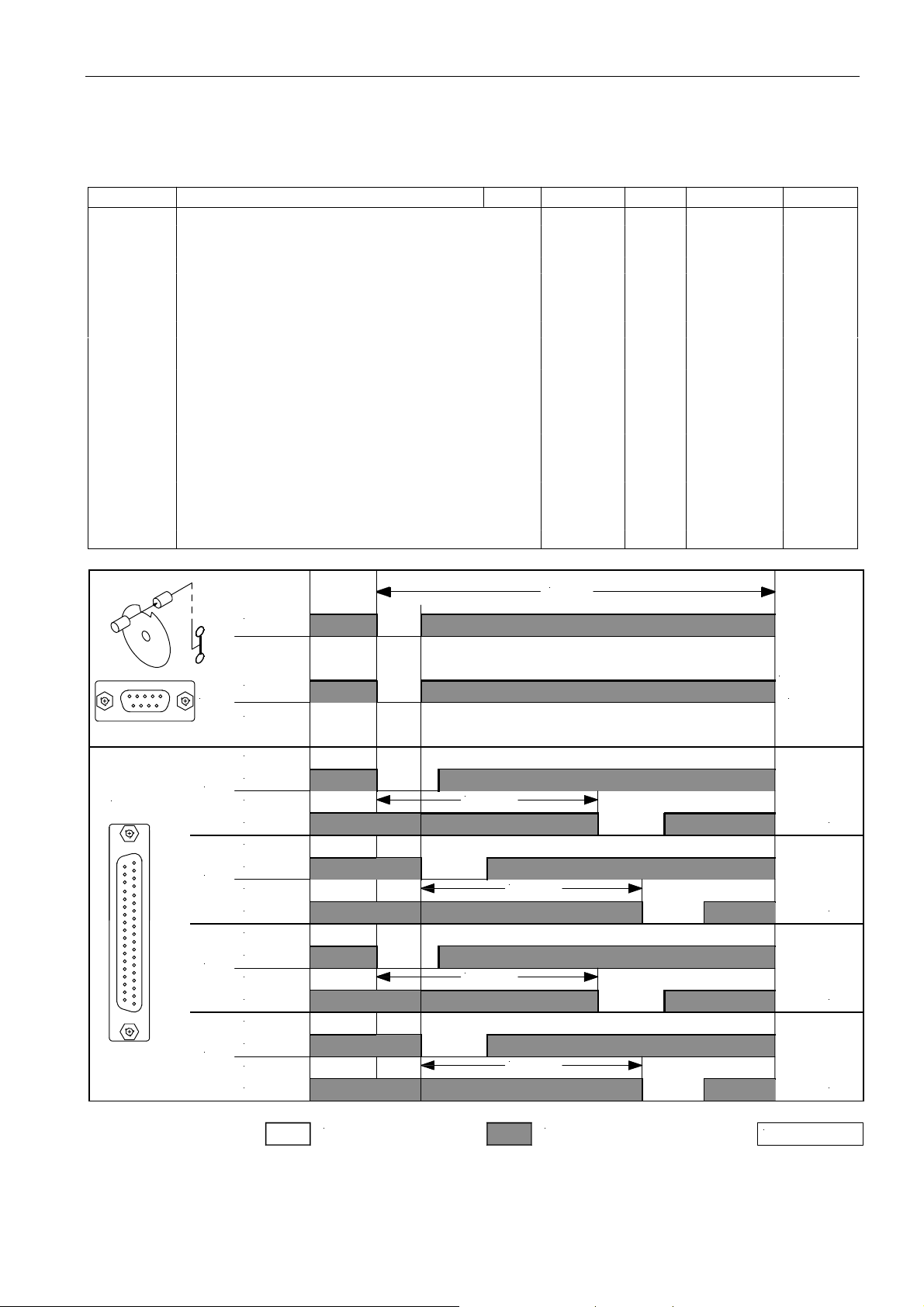
69
EFKA AB320A5200
Supplier Level
Code no. 311 with control operation
Code no. 3112 with control panel operation
Parameter Designation Unit max min Preset Ind.
270 PGm Connection of a sensor e. g. light barrier sensor to 5 0 0 *) A
light barrier socket B18/7. Selection of the desired
function!
0 = The positions are generated by means of the
transmitter incorporated in the motor and can be set
by means of parameter 171.
1 = Setting the sensor to position 2.
Set position 1 using parameter 271, starting from
leading edge position 2.
2 = Setting the sensor to position 2.
Set position 1 using parameter 271, starting from
trailing edge position 2.
3 = Setting the sensor to position 1.
Set position 2 using parameter 271, starting from
leading edge position 1.
4 = Setting the sensor to position 1.
Set position 2 using parameter 271, starting from
trailing edge position 1.
5 = No position sensor available. The drive stops
unpositioned. The thread trimmer function is
suppressed with this setting.
ST2
IN
OUT
OUT
OUT
OUT
SEN
POS
B18/7
POS2
ST2/21
POS1
ST2/20
POS2
ST2/21
POS1
ST2/20
POS1
ST2/20
POS2
ST2/21
POS1
ST2/20
POS2
ST2/21
360°
+5V
0V
Pa 271
270 = 1270 = 3270 = 4 270 = 2
Pa 271
Pa 271
Pa 271
= 0V
= high
*) Depending on the selected mode. See table at the beginning of the List of Parameters!
0256/ SEN- 1
Page 68
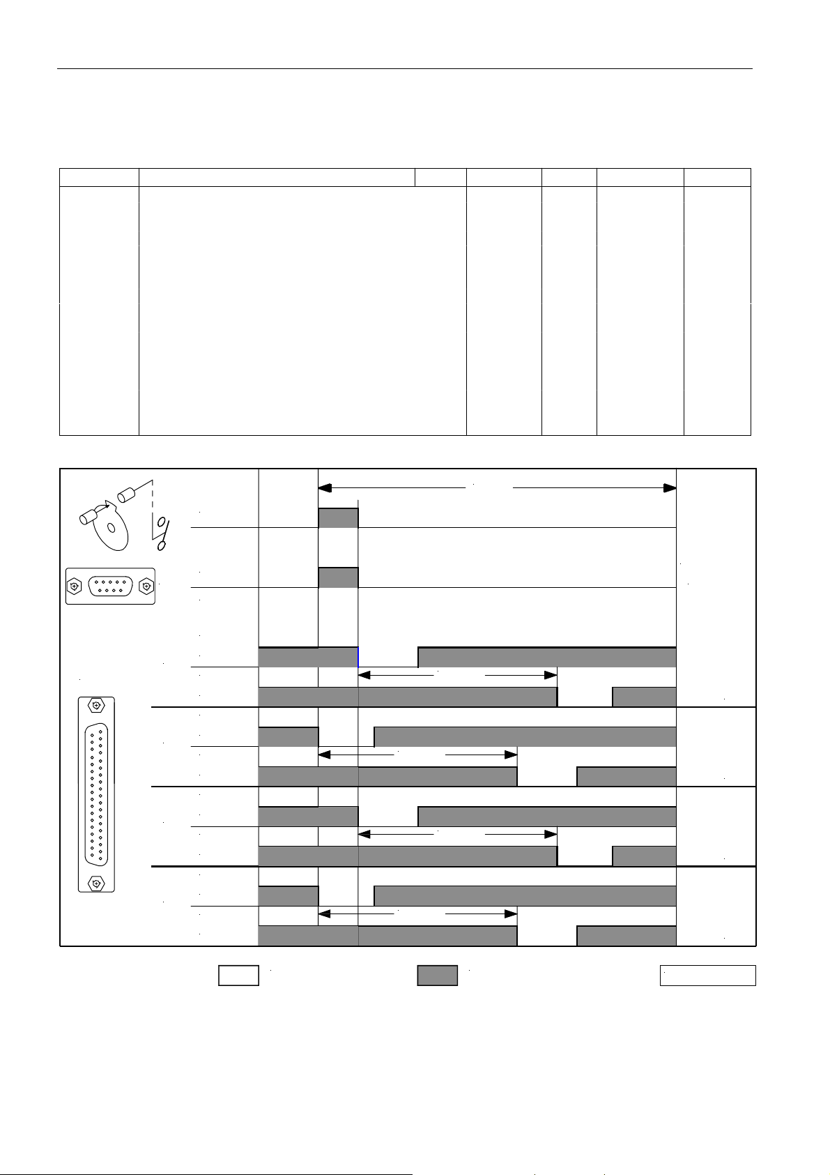
EFKA AB320A5200
70
Supplier Level
Code no. 311 with control operation
Code no. 3112 with control panel operation
Parameter Designation Unit max min Preset Ind.
270 PGm Connection of a sensor e. g. light barrier sensor to 5 0 0 *) A
light barrier socket B18/7. Selection of the desired
function!
0 = Function as in table on previous page!
1 = Setting the sensor to position 2.
Set position 1 using parameter 271, starting from
trailing edge position 2.
2 = Setting the sensor to position 2.
Set position 1 using parameter 271, starting from
leading edge position 2.
3 = Setting the sensor to position 1.
Set position 2 using parameter 271, starting from
trailing edge position 1.
4 = Setting the sensor to position 1.
Set position 2 using parameter 271, starting from
leading edge position 1.
5 = Function as in table on previous page!
ST2
IN
OUT
OUT
OUT
OUT
SEN
POS
B18/7
POS2
ST2/21
POS1
ST2/20
POS2
ST2/21
POS1
ST2/20
POS1
ST2/20
POS2
ST2/21
POS1
ST2/20
POS2
ST2/21
360°
+5V
0V
Pa 271
270 = 1270 = 3270 = 4 270 = 2
Pa 271
Pa 271
Pa 271
= 0V
= high
*) Depending on the selected mode. See table at the beginning of the List of Parameters!
0256/ SEN- 2
Page 69
71
EFKA AB320A5200
Supplier Level
Code no. 311 with control operation
Code no. 3112 with control panel operation
Parameter Designation Unit max min Preset Ind.
271 PGr Number of angular degrees after the sensor degrees 255 0 180 *) A
position on the machine handwheel
272 trr Transmission ratio between motor shaft and machine 255 020 100 *) A
shaft (calculation formula see instruction manual!)
The transmission ratio should be determined and
indicated as precisely as possible!
273 Asi Signals M8, M9, M10 On/Off 1 0 0 A
(0 = Off, 1 = On)
274 Ad1 Delay time of signal M8 at the start of the seam ms 2550 **) 0 40 *) A
275 At1 ON period of signal M8 at the start of the seam ms 2550 **) 0 150 *) A
276 Ad2 Delay time of signal M9 at the start of the seam ms 2550 **) 0 50 A
277 At2 ON period of signal M9 at the start of the seam ms 2550 **) 0 60 A
278 Ad3 Delay time of signal M10 at the start of the seam ms 2550 **) 0 40 A
279 At3 ON period of signal M10 at the start of the seam ms 2550 **) 0 350 A
280 kd1 Delay time output M1 ms 2550 **) 0 0 *) A
281 kt1 ON period output M1 ms 2550 **) 0 100 *) A
282 kd2 Delay time output M2 ms 2550 **) 0 100 *) A
283 kt2 ON period output M2 ms 2550 **) 0 100 *) A
284 kd3 Delay time output M3 ms 2550 **) 0 200 *) A
285 kt3 ON period output M3 ms 2550 **) 0 100 *) A
286 kd4 Delay time output M4 ms 2550 **) 0 300 *) A
287 kt4 ON period output M4 ms 2550 **) 0 100 *) A
288 kdF Delay time until sewing foot On ms 2550 **) 0 380 *) A
289 kt5 ON period output M7 ms 2550 **) 0 1000 A
*) Depending on the selected mode. See table at the beginning of the List of Parameters!
**) When programming the 3-digit or 4-digit control parameter values (without control panel), the 2-digit or 3-digit
value displayed must be multiplied by 10.
Page 70
EFKA AB320A5200
72
Supplier Level
Code no. 311 with control operation
Code no. 3112 with control panel operation
Parameter Designation Unit max min Preset Ind.
290 FAM 0 = Lockstitch mode: 24 0 5 A
(FA1, FA2, FA3, FA1+FA2); e. g. Brother
Dürkopp Adler, Mitsubishi, Pfaff, Toyota
»Slide-in strip for V810 and V820 = 1«
2 = Lockstitch mode: e. g. Singer (212 UTT)
»Slide-in strip for V810 and V820 = 1«
3...= Lockstitch mode:
e. g. Dürkopp Adler (models 767, N291)
»Slide-in strip for V810 and V820 = 1«
4 = Chainstitch mode: e. g. (US80A)
»Slide-in strip for V810 = 5«
»Slide-in strip for V820 = 3«
5 = Chainstitch mode in general:
M1, M2, M3 and M4 parallel sequence
»Slide-in strip for V810 = 5«
»Slide-in strip for V820 = 3«
6 = Chainstitch mode with tape cutter and/or
fast scissors and M1 / M2 at the seam end
»Slide-in strip for V810 = 5«
»Slide-in strip for V820 = 3«
7 = Overlock mode: e. g. (AC62AV1461)
»Slide-in strip for V810 = 7«
»Slide-in strip for V820 = 5«
8 = Backlatch mode: Pegasus
»Slide-in strip for V810 = 7«
»Slide-in strip for V820 = 5«
9 = Backlatch mode: Yamato
»Slide-in strip for V810 = 7«
»Slide-in strip for V820 = 5«
10 = Lockstitch mode:
Union Special (63900AMZ »replacement for
US80A«) and on Refrey lockstitch machines
»Slide-in strip for V810 and V820 = 1«
14 = Lockstitch mode: Juki (5550-6, 5550-7)
»Slide-in strip for V810 and V820 = 1«
15 = Backlatch mode: Pegasus (SSC100)
»Slide-in strip for V810 = 7«
»Slide-in strip for V820 = 5«
16 = Overlock mode: feed-off-the-arm machines
e. g. Yamato (FD62)
»Slide-in strip for V820 = 7«
17 = Chainstitch mode: Pegasus (stitch lock)
»Slide-in strip for V810 = 5«
»Slide-in strip for V820 = 3«
20 = Lockstitch mode: Juki (LU1510-7)
»Slide-in strip for V810 and V820 = 1«
21 = Chainstitch mode with stitch lock:
Yamato (VG2730-156M)
»Slide-in strip for V810 = 5«
»Slide-in strip for V820 = 3«
23 = Lockstitch mode: Dürkopp Adler (271...275)
»Slide-in strip for V810 and V820 = 1«
24 = Chainstitch mode: Pegasus (MHG-100)
Modes 1, 11...13, 18, 19, 22 are selectable, but their
functions correspond to mode 0!
Page 71
73
EFKA AB320A5200
Supplier Level
Code no. 311 with control operation
Code no. 3112 with control panel operation
Note
When selecting the trimming mode by means of parameter 290, the connected V810 or V820 control panel is
automatically sensed and the corresponding slide-in strip number is selected by means of parameter 291 and 292,
respectively. Should a different strip be inserted, its number can be set by means of parameter 291 and 292, respectively,
after having selected the trimming mode.
Parameter Designation Unit max min Preset Ind.
291 810 Select slide-in strip number for the V810 control 8 1 1 *) A
panel (illustrations of slide-in strips see the
following chapter 9)
292 820 Select slide-in strip number for the V820 control 10 1 1 *) A
panel (illustrations of slide-in strips see the
following chapter 9)
293 tF1 Selection of the input function by means of the 43 0 17 *) A
(A) key “F1” on the V810/V820 control panel
0 = No function
1 = Needle up/down
2 = Needle up
3 = Single stitch (basting stitch)
4 = Full stitch
5 = Needle to position 2
6...12 = No function
13 =High lift for walking foot with speed limitation
n10 (operational mode not stored)
14 =High lift for walking foot with speed limitation
n10 (operational mode stored)
15 = Tape cutter / fast scissors
(in chainstitch and overlock mode)
16 =Intermediate backtack/intermediate stitch
condensing
17 = Stitch regulator suppression / recall
18 = No function
19 = Reset bobbin thread monitor if parameter
030 = >0
20...43 =No function
294 tF2 Selection of the input function by means of the 43 0 1 *) C
(B) key “F2” on the V810/V820 control panel
Functions of the key as with parameter 293
295 nAM Switch proximity switches for inputs in2, in7, in8, in9 1 0 0 A
296 M08 Functions of signal M8 5 0 0 *) A
0 = Signal M8 Off
1 = Signal hemmer foot On at the start of the seam
with pedal in pos. -1 or –2 and in the seam with
machine running
2 = Signal hemmer foot On at the start of the seam
with pedal in pos. -1 or –2 and remains active in
the seam
3 = Signal M8 as center cutter
4 = Signal M8 with needle up / down
5 = Signal M8 alternating with M3 with “fast scissors”
on overlock machines in mode 16,
if parameter 232=1 has been selected
*) Depending on the selected mode. See table at the beginning of the List of Parameters!
Page 72
EFKA AB320A5200
74
Supplier Level
Code no. 311 with control operation
Code no. 3112 with control panel operation
Parameter Designation Unit max min Preset Ind.
297 M11 Functions of signal M11 5 0 0 A
0 = Function according to setting of parameter 290.
1 = Signal M11 is switched on whenever the light
barrier is covered
2 = Signal M11 is switched on whenever the light
barrier is uncovered
3 = Signal M11 is switched on only after light barrier
uncovered and/or covered until seam end
4 = Signal M11 is switched on as with setting 3.
Signal M5 (machine running), however, is
switched off while signal M11 is issued.
When signal M11 is issued, signal M6 (machine
at standstill) is also immediately issued.
5 = Signal M11 is switched on from “light barrier
sensing“, “pedal in pos. –2“ or “‘hemmer foot
signal’ key off“ onwards.
298 nSo Backtack synchronization On/Off 1 0 0 A
299 nrS Backtack synchronization speed RPM 3000 **) 200 400 A
300 AA1 Selectable power transistors for signal A1 12 0 0 A
0 =No function
1 =Signal on output M1
2 =Signal on output M2
3 =Signal on output M3
4 =Signal on output M4
5 =Signal on output M5
6 =Signal on output M6
7 =Signal on output M7
8 =Signal on output M8
9 =Signal on output M9
10 = Signal on output M10
11 = Signal on output M11
12 = Signal on output VR
301 So1 Issue signal A1 3 0 0 A
0 =Signal until seam end (according to setting of
parameter 320)
1 =Signal over time
2 =Signal until seam end and drive stops
3 =Signal during stitch counting (according to setting
of parameter 309)
302 tr1 Starting point for signal A1 3 0 0 A
0 =Start at the beginning of the seam
1 =Start of the signal triggered by light barrier sensing
2 =Start of the signal when the drive stops at the seam
end
3 =Start from light barrier covered onwards at the
beginning of the seam
303 do1 Delay of signal A1 2 0 1 A
0 =No delay until signal On
1 =Delay over time until signal On
2 =Delay over stitches until signal On
304 dt1 Delay time until signal A1 On ms 2550 **) 0 0 A
305 St1 ON period of signal A1 ms 2550 **) 0 0 A
306 nA1 Speed mode when signal A1 is On 2 0 0 A
0 =Pedal controlled speed
1 =Limited speed n9
2 =Limited speed n11
*) Depending on the selected mode. See table at the beginning of the List of Parameters!
**) When programming the 3-digit or 4-digit control parameter values (without control panel), the 2-digit or 3-digit
value displayed must be multiplied by 10.
Page 73
75
EFKA AB320A5200
Supplier Level
Code no. 311 with control operation
Code no. 3112 with control panel operation
Parameter Designation Unit max min Preset Ind.
307 A1 Signal A1 On/Off 1 0 0 A
308 dA1 Stitches delaying signal A1 stitches 999 0 0 A
309 cA1 Stitch counting during signal A1 stitches 999 0 0 A
310 AA2 Selectable power transistors for signal A2 12 0 0 A
0 =No function
1 =Signal on output M1
2 =Signal on output M2
3 =Signal on output M3
4 =Signal on output M4
5 =Signal on output M5
6 =Signal on output M6
7 =Signal on output M7
8 =Signal on output M8
9 =Signal on output M9
10 = Signal on output M10
11 = Signal on output M11
12 = Signal on output VR
311 So2 Issue signal A2 3 0 0 A
0 =Signal until seam end (according to setting of
parameter 320)
1 =Signal over time
2 =Signal until seam end and drive stops
3 =Signal during stitch counting (according to setting
of parameter 319)
312 tr2 Starting point for signal A2 3 0 0 A
0 =Start at the beginning of the seam
1 =Start of the signal triggered by light barrier sensing
2 =Start of the signal when the drive stops at the seam
end
3 =Start from light barrier covered onwards at the
beginning of the seam
313 do2 Delay of signal A2 2 0 1 A
0 =No delay until signal On
1 =Delay over time until signal On
2 =Delay over stitches until signal On
314 dt2 Delay time until signal A2 On ms 2550 **) 0 0 A
315 St2 ON period of signal A2 ms 2550 **) 0 0 A
316 nA2 Speed mode when signal A2 is On 2 0 0 A
0 =Pedal controlled speed
1 =Limited speed n9
2 =Limited speed n11
317 A2 Signal A2 On/Off 1 0 0 A
318 dA2 Stitches delaying signal A2 stitches 999 0 0 A
319 cA2 Stitch counting during signal A2 stitches 999 0 0 A
320 bP0 Switch-off time of signals A1 and A2 1 0 0 A
0 =Signals effective until seam end
1 =Signals effective until pedal is in pos. 0 (neutral)
321 Std Suppression of the seam when 0 stitches are set 1 0 0 A
0 =Suppression Off
1 =Suppression On
322 dkn 0 = Correction seam Off 2 0 0 A
1 =Correction seam On
2 =Interruption of seam or pattern by thread trimmer
*) Depending on the selected mode. See table at the beginning of the List of Parameters!
**) When programming the 3-digit or 4-digit control parameter values (without control panel), the 2-digit or 3-digit
value displayed must be multiplied by 10.
Page 74
EFKA AB320A5200
76
Supplier Level
Code no. 311 with control operation
Code no. 3112 with control panel operation
Parameter Designation Unit max min Preset Ind.
323 FLn 0 = Sewing foot is not lifted after power On 1 0 0 A
1 =Sewing foot is lifted after power On
This function is enabled only if TEACH IN is On
324 ti 0 = Teach-in Off 1 0 0 A
1 =Teach-in On
Teach-in programming is possible only with V820.
Execution of pattern is possible without V820.
500 Sir Recall of Fast Installation Routine (SIR)
(see description on page 8!)
Param eter
A1
A2
301
311
302
303
313312
304 305
314 315
[m s ] [m s]
308
318
[S t]
309
319
[S t]
NA
LS
NE
FA- E P= 0
2
0
2
1
2
0
0
100
100 100
100
0
0
0
0 100
0
0
0
0
0
100
0
100
0
100100
0
0
10
0
0
0
10
0
10
0
0
0
0
0
0
0
10
10
10
0
0
0
0
1 0
0 11
0 1
1
1 0
1 1 1
3
1
3
1
3
1
11
2
1 0
2
1 1
NA = Start of seam
LS = Light barrier uncovered or covered at the seam end
NE = Seam end
FA-E = End thread trimming operation
P=0 = Pedal in pos. 0 (neutral)
St = Stitches
100
10
100
100100
10
10 10
100
10
100
10
100
100
100
0256/ BILD4
Parameter 320 = 0 ! Signals enabled according to setting of parameter 301/311.
Parameter 320 = 1 ! Signals enabled until pedal is in pos. 0 (neutral).
Page 75
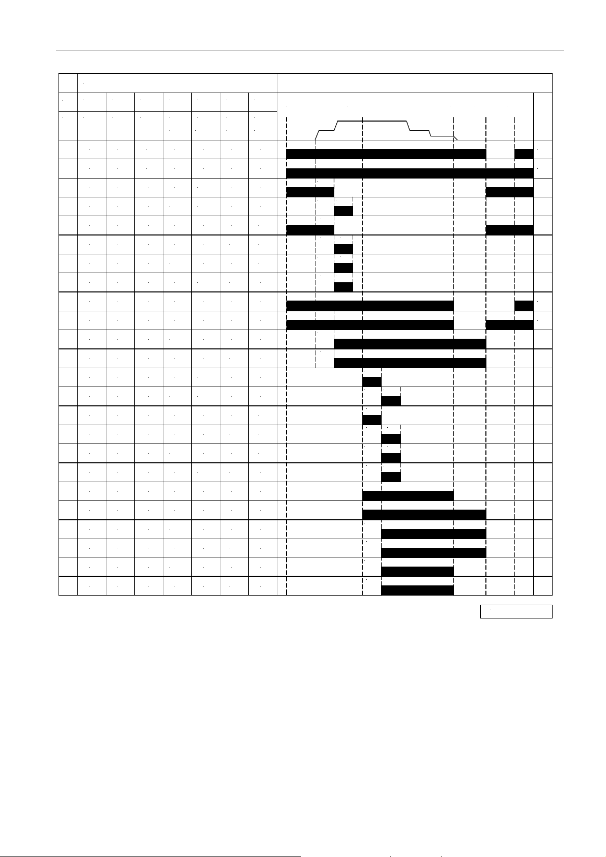
Param eter
301
A1
311
A2
302
303
313312
304 305
314 315
[m s ] [m s ]
308
318
[S t]
309
319
[S t]
NA
77
LS- D
EFKA AB320A5200
FA- E P= 0
NE
0
0 0
0
0 0
1
0 0
1
3
0 0
3
0
3
1 0
2
0 0
2
0 0
0 0 1
0 0
3
1
3
1 1
33
33 2
33
3 2
1
10
2
10
2
2
0
0
1
0 0
0 0
0 100
0
0
100
0
0
100
0
0 100
0
0
100
0
100100
0
0
0
1000
0
0
0
0
100100
0
0
0
100
0
0
0
0
0
10
0
10
0
0
0
10
0
0
0
10
0
10
0
0
0
0
10
10
10
0
0
0
0
0
0
0
10
10
10
0
100
10
101010
100
10
100
10
100100
100
100
100
10
10
100
10
1)
2)
1)
2)
100
10
10
100
3
2
3
0
3
0
3
0
32
32 2
0
0
0
0
100
1
2
0
100
1
0
0
0
0
0
10
0
0
10
0
0
0
0
0
0
0
0
0
0
100
10
100
10
NA = Start of seam
LS-D = Light barrier uncovered ! covered (parameter 131 = 1 and parameter 132 = 0)
NE = Seam end
FA-E = End thread trimming operation
P=0 = Pedal in pos. 0 (neutral)
St = Stitches
1) Seam end after stitch counting or light barrier sensing
2) Seam end after pedal in pos. -2
0256/ B ILD3
Page 76
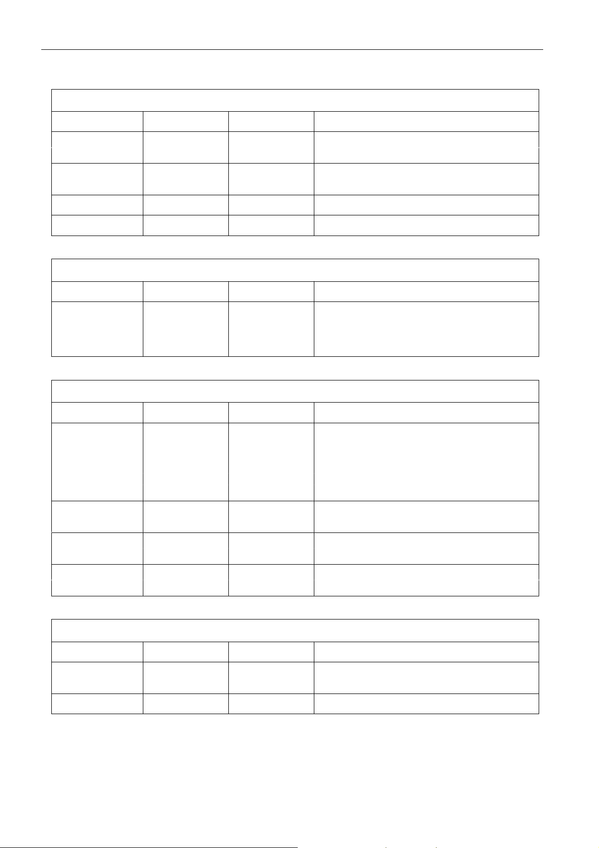
EFKA AB320A5200
78
7 Error Displays
General Information
On the control On the V810 On the V820 Signification
A1 InF A1 InFo A1 Pedal not in neutral position, when turning
the machine on
A2 -StoP- blinking -StoP- blinking + Mac hi ne run bloc kage
symbol display
A3 InF A3 InFo A3 Reference position is not set
A7 Symbol blinking Symbol blinking Bobbin thread monitor
Programming Functions and Values (Parameters)
On the control On the V810 On the V820 Signification
Returns to 000 Returns to 0000 Like V810 + Wrong code number or parameter number
or to last or to last display InFo F1 input
parameter number parameter
number
Serious Condition
On the control On the V810 On the V820 Signification
E1 InF E1 InFo E1 After power On, position transmitter or
commutation transmitter defective, or
connecting cables have been changed by
mistake. During operation or after a sewing
cycle, only position transmitter defects can
be identified.
E2 InF E2 InFo E2 Line voltage too low, or time between power off
and power on too short.
E3 InF E3 InFo E3 Machine blocked or does not reach the desired
speed.
E4 InF E4 InFo E4 Control disturbed by deficient grounding or
loose contact.
Hardware Disturbance
On the control On the V810 On the V820 Signification
H1 InF H1 InFo H1 Commutation transmitter cord or frequency
converter disturbed.
H2 InF H2 InFo H2 Processor disturbed
Page 77
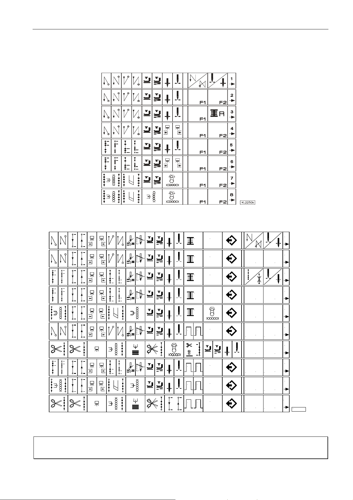
79
8 Slide-in Strips for the V810/V820 Control Panels
Slide-in strips for the V810 control panel
EFKA AB320A5200
Slide-in strips for the V820 control panel
R
R
R
R
R
1 2
1 2
1 2
F
F
F
F
F
F
F
F1
F1
F1
INSERT DELETE
F1
F1
F1
INSERT DELETE
F1
INSERT DELETE
1
2
F2
3
4
F2
5
F2
6
F2
7
F2
8
F2
9
F2
1 2
F
INSERT DELETE
F1
F2
10
KL2256e
Note
When changing the setting of parameters 291 / 292, the V810 / V820 functions change as well, save function keys
F1 / F2 which are influenced by parameters 293 /294.
Page 78

FRANKL & KIRCHNER GMBH & CO KG
SCHEFFELSTRASSE 73 – D-68723 SCHWETZINGEN
TEL.: (06202)2020 – TELEFAX: (06202)202115
email: [email protected] – http://www.efka.net
OF AMERICA INC.
3715 NORTHCREST ROAD – SUITE 10 – ATLANTA – GEORGIA 30340
PHONE: (770)457-7006 – TELEFAX: (770)458-3899 – email: [email protected]
ELECTRONIC MOTORS SINGAPORE PTE. LTD.
67, AYER RAJAH CRESCENT 05-03 – SINGAPORE 139950
PHONE: 7772459 – TELEFAX: 7771048 – email: [email protected]
1(1)-191101 B (402286 EN)
 Loading...