

Efka dc 1500 Instruction Manual
CONTROL FP220A5911
INSTRUCTION MANUAL
No. 402295 English
FRANKL & KIRCHNER EFKA OF AMERICA INC. EFKA ELECTRONIC MOTORS
GMBH & CO KG SINGAPORE PTE. LTD.
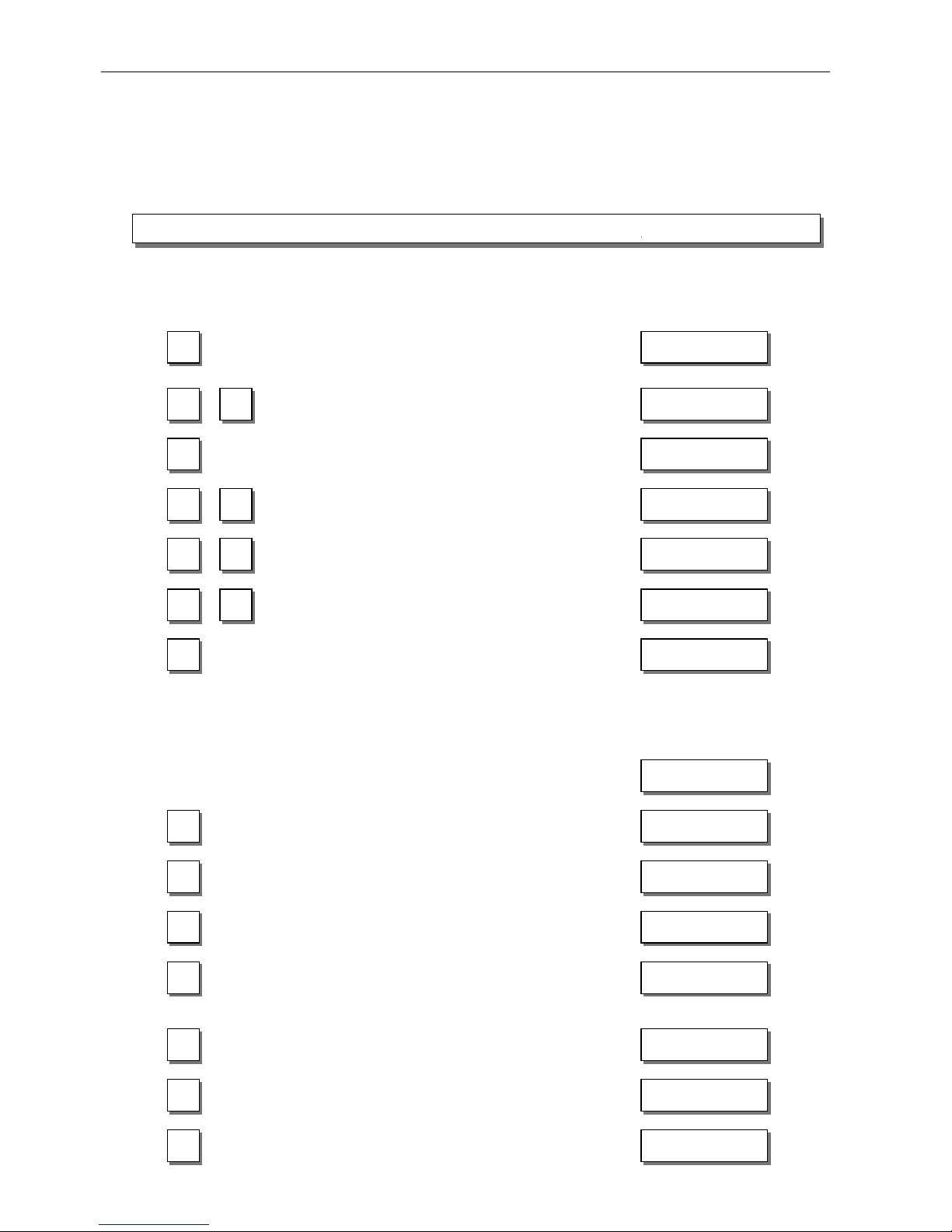
+
-
>
>
P
E
0
I
KL2334a

EFKA FP220A5911
3
CONTENTS Page
1 Important Safety Instructions 7
2 Range of Applications 8
2.1 Use in Accordance with Regulations 9
3 Scope of Supply 9
3.1 Special Accessories 10
4 Use of the C200 Compiler 11
5 Connection of Stepping Motor Controls to the FP220A Control 12
5.1 SM210A Control Settings for Operating the FP220A Control 12
5.2 FP220A Control Settings 12
6 Control Operation without Control Panel 13
6.1 Access Authorization upon Command Input 13
6.2 Programming the Code Number 14
6.3 Parameter Selection 15
6.3.1 Direct Selection 15
6.3.2 Changing Parameter Values 16
6.3.3 Parameter Selection with the +/- Keys 17
6.3.4 Immediate Storage of All Changed Data 17
6.4 Changing All Parameter Values at the Operator Level 18
6.5 Function Switchover 18
6.6 Direct Input of Maximum Speed Limitation without Control Panel 18
6.7 Program Identification on the Control 19
7 Control Operation with Control Panel 20
7.1 Operation of the V810 Control Panel 20
7.1.1 Code Number Input on the V810 Control Panel 20
7.1.2 Parameter Input at the Operator Level on the V810 Control Panel 20
7.1.3 Parameter Input at the Technician/Supplier Level on the V810 Control Panel 21
7.2 V820 Control Panel Operation 21
7.2.1 Code Number Input on the V820 Control Panel 21
7.2.2 Parameter Input at the Operator Level on the V820 Control Panel 22
7.2.3 Parameter Input at the Technician/Supplier Level on the V820 Control Panel 22
7.3 Program Identification 23
7.4 Direct Input of Maximum Speed Limitation (DED) with Control Panel 23
7.4.1 Setting on the V810 Control Panel 23
7.4.2 Setting on the V820 Control Panel 23
7.5 Keys for Background Information (HIT) with V820 24
7.5.1 Example of HIT 24
7.5.2 Further Functions of the V810/V820 Control Panels 25
7.5.3 Special Functions of the V820 Control Panel 26
7.6 Programming of Seams (TEACH IN) 27
7.6.1 Programming after Code Number Input 28
7.6.2 Programming without Code Number Input 28
7.6.3 Detailed Example 30
7.6.4 Inserting a Seam or Pattern 31
7.6.5 Deleting a Seam or Pattern 32
7.6.6 Execution (Pattern) Mode 32
7.6.7 Further Settings for TEACH IN 32
8 Putting into Service 34
9 Setting and Putting into Service with the Aid of the Fast Installation Routine (SIR) 34

EFKA FP220A5911
4
CONTENTS Page
10 Setting the Basic Functions 36
10.1 Direction of Motor Rotation 36
10.2 Transmission Ratio 36
10.3 Selection of Functional Sequences (Thread Trimming Operations) 36
10.4 Functions of the Keys Inputs in1...i10 41
10.5 Positioning Speed 41
10.6 Maximum Speed Compatible with the Sewing Machine 41
10.7 Maximum Speed 41
10.8 Positions 42
10.8.1 Setting the Reference Position (Parameter 270 = 0) 44
10.8.2 Setting the Positions on the Control (Parameter 270 = 0) 44
10.8.3 Setting the Positions on the V810 Control Panel (Parameter 270 = 0) 45
10.8.4 Setting the Positions on the V820 Control Panel (Parameter 270 = 0) 45
10.9 Display of the Signal and Stop Positions 46
10.10 Positioning Shift 47
10.11 Braking Characteristics 47
10.12 Braking Power at Standstill 47
10.13 Starting Characteristics 47
10.14 Inputs for Proximity Switches 48
10.15 Actual Speed Display 48
11 Functions with or without Control Panel 49
11.1 Softstart 49
11.1.1 Softstart Speed 49
11.1.2 Softstart Stitches 49
11.2 Sewing Foot Lifting 49
11.3 Start Backtack/Start Stitch Condensing 51
11.3.1 Speed n3 at the Start of the Seam 51
11.3.2 Stitch Counting for Start Backtack/Start Stitch Condensing 51
11.3.3 Stitch Correction and Speed Release 52
11.3.4 Double Start Backtack 52
11.3.5 Single Start Backtack / Start Stitch Condensing 52
11.4 End Backtack / End Stitch Condensing 52
11.4.1 Speed n4 at the Seam End 53
11.4.2 Stitch Counting for End Backtack/End Stitch Condensing 53
11.4.3 Stitch Correction and Last Stitch Backward 53
11.4.4 Double End Backtack/End Stitch Condensing 53
11.4.5 Single End Backtack / End Stitch Condensing 53
11.4.6 Backtack Synchronization 54
11.5 Start Ornamental Backtack/Stitch Condensing 54
11.6 End Ornamental Backtack/Stitch Condensing 54
11.7 Intermediate Backtack 55
11.8 Stitch Regulator Suppression/Recall 55
11.9 Holding Power of the Stitch Regulator Solenoid 55
11.10 Reverse Motor Rotation 56
11.11 Unlocking the Chain (Mode 4/5/6/7/16) 56
11.12 Machine Run Blockage (Safety Switch) 57
11.13 High Lift for Walking Foot Signal Output M6 / Flip-Flop 1 58
11.13.1 High Lift Walking Speed 58
11.13.2 High Lift Walking Speed Run-Out Time 58
11.13.3 High Lift Walking Stitches 59
11.13.4 High Lift for Walking Foot Operational Mode Not Stored (Parameters 240...249 = 13) 59
11.13.5 High Lift for Walking Foot Operational Mode Stored /Flip-Flop 1
(Parameters 240...249 = 14) 59

EFKA FP220A5911
5
CONTENTS Page
11.14 Speed Depending on High Lift 59
11.14.1 Operating Mode of Speed Limitation Depending on High Lift 59
11.14.2 Setting the Speed Limitation Depending on High Lift with the V820 Control Panel 60
11.14.3 Setting the Speed Limitation Depending on High Lift with the V810 Control Panel 61
11.14.4 Potentiometer Adjustment on JUKI Machine Model LU-2210/LU2260 62
11.15 Speed Limitation n9 62
11.16 Speed Limitation n11 with Signal Output M10 / Flip-Flop 2 62
11.17 Disabling of Flip-Flop Functions at the Seam End 63
11.18 Bobbin Thread Monitor 63
11.19 Thread Trimming Operation 64
11.19.1 Thread Trimmer/Thread Wiper (Modes 0, 2, 3, 10, 14, 20 and 23) 64
11.19.2 Trimming Speed 64
11.19.3 Chainstitch Thread Trimmer (Modes 4, 5, 6, 21 and 24) 64
11.19.4 Chainstitch Machine Trimming Signal Times 65
11.20 Bag Sewing Machine Functions (Mode 5) 65
11.21 Stitch Lock Machine Functions (Mode 21) 65
11.22 Functions for Pegasus MHG-100 Machine (Mode 24) 66
11.23 Overlock Machine Functions (Mode 7) 66
11.23.1 Chain Suction Signal 66
11.23.2 Start and End Counts 67
11.24 Function of Output Signal M8 67
11.25 Function of Output Signal M11 68
11.26 Tape Cutter/Fast Scissors (Modes 6/7/15/16) 68
11.26.1 Functions for Mode 6 68
11.26.2 Functions for Mode 7 68
11.26.3 Functions for Mode 15 69
11.26.4 Functions for Mode 16 70
11.27 Manual Tape Cutter/Fast Scissors 71
11.28 Manual Stacker 72
11.29 Selection of Signals M8, M9 and M10 at the Start of the Seam 72
11.30 Seam with Stitch Counting 72
11.30.1 Stitches for Stitch Counting 72
11.30.2 Stitch Counting Speed 73
11.30.3 Seam with Stitch Counting When Light Barrier Is On 73
11.31 Free Seam and Seam with Light Barrier 73
11.32 Light Barrier 74
11.32.1 Speed after Light Barrier Sensing 74
11.32.2 General Light Barrier Functions 74
11.32.3 Reflection Light Barrier LS002 75
11.32.4 Light Barrier Monitoring 75
11.32.5 Automatic Start Controlled by Light Barrier 75
11.32.6 Light Barrier Filter for Knitted Fabrics 75
11.32.7 Functional Variations of the Light Barrier Input 76
11.33 Switching Functions of Inputs in1...i10 76
11.34 Software Debouncing of All Inputs 77
11.35 F1/F2 Function Key Assignment on the V810/V820 Control Panels 77
11.36 Functioning of Handwheel when Pressing a Key 78
11.37 Speed Limitation by means of External Potentiometer 78
11.38 Signals A1 and A2 79
11.39 Signal “Machine Running“ 81
11.40 Signal Output Position 1 81
11.41 Signal Output Position 2 81
11.42 Signal Output 512 Impulses per Rotation 82
11.43 Actuator 82
11.44 Audible Signal 83

EFKA FP220A5911
6
CONTENTS Page
12 Signal Test 83
12.1 Signal Test Using the Incorporated Control Panel or the V810/V820 83
13 Error Displays 85
14 Operating Elements of the V810 Control Panel 86
15 Operating Elements of the V820 Control Panel 87
EFKA FP220A5911
7
1 Important Safety Instructions
When using an EFKA drive and accompanying devices (e g
for sewing machines), basic safety precautions should
always be followed, including the following:
! Read all instructions thoroughly before using this drive.
! Drive, its accessories and accompanying devices should
be mounted and put into operation by qualified personnel
in accordance with the guidelines provided in the
instruction manual.
To reduce the risk of burns, fire, electric shock, or
personal injury:
! Use this drive only for its intended use as described in the
instruction manual.
! Use only attachments recommended by the manufacturer
or as contained in the instruction manual.
!
Do not operate without corresponding protective devices.
!
Never operate this drive if one or more parts (e. g. cables,
plugs) are damaged, if it is not working properly, if any
damages can be identified or are to be suspected (e. g.
after it has been dropped). Only qualified personnel are
authorized to make adjustments, eliminate faults and
complete repair work.
!
Never operate the drive with the air openings blocked.
Keep ventilation openings of the drive free from the
accumulation of lint, dust and loose cloth.
! Never drop or insert any object into any opening.
! Do not use drive outdoors.
! Do not operate where aerosol (spray) products are being
used or where oxygen is being administered.
! To disconnect, turn off main switch, then remove plug
from outlet.
! Do not unplug by pulling on cord. To unplug, grasp the
plug, not the cord.
!
Keep fingers away from all moving machine parts. Special
care is required e. g. around the sewing machine needle
and the V-belt.
!
Before mounting and adjusting accompan ying devic es, i. e.
position transmitter, reversing device, light barrier, etc.,
disconnect drive from mains (turn off main switch,
remove mains plug from outlet [DIN VDE 0113 part 301;
EN 60204-3-1; IEC 204-3-1]).
! Always switch off (0) machine and remove plug from
outlet, when removing covers, mounting accompanying
devices, position transmitter especially, light barrier, etc.,
or any other devices mentioned in the instruction manual.
! Only qualified personnel are authorized to work on the
electrical components.
! Work on high voltage circu it areas is forbidd en, except as
stated in the respective regulati ons, e.g. DIN VDE 0105
part 1.
! Only specially trained personnel are authorized to
complete repair work.
!
Cables to be wired must be protected again st expectable
strain and fastened adequ ately.
! Cables near moving machine parts (e. g. V-belts) must be
wired at a minimum distance of 25 mm (see DIN VDE
0113 part 301; EN 60204-3-1; IEC 204-3-1).
! For safety it is preferred to wire the cables separately from
each other.
! Before connecting the mains line make sure that the mains
voltage corresponds to the specifications on the motor
rating plate and on the nameplate of the power pack.
!
Connect this drive to a properly grounded outlet only. See
Grounding Instructions.
!
Electric accompanying devices an d accessories must only
be connected to safety low voltage.
!
EFKA DC drives are protected accordin g to overvoltage
class 2 (DIN VDE 0160 § 5.3.1).
! Observe all safety guidelines before undertaking
conversions or modifications.
! For repair and maintenance use only original replacement
parts.
Warnings in the instruction manual
which point out particular risks of
personal injury or risk to the machine
are marked with this symbol wherever
applicable.
This symbol is a warning on the control
and in the instruction manual. It
indicates hazardous voltage.
CAUTION – In the case of failure this
area can be current-carrying even a fter
having turned the power off (non
discharged capacitors).
! The drive is not an independently operating unit, but is
designed to be incorporated into the machinery. It must
not be put into service until the machinery into which it is
to be incorporated has b een declared in conformity with
the provisions of the EC Directive.
Save these instructions for future reference.
EFKA FP220A5911
8
2 Range of Applications
The drive is suitable for lockstitch, chainstitch and overlock machines of various manufacturers. Furthermore, stepping
motor operation is possible with the SM210A control. See connection scheme in the List of Parameters.
With the help of adapter cords (adapter cords see Special Accessories), the drive can be used with the following
controls replacing previous models:
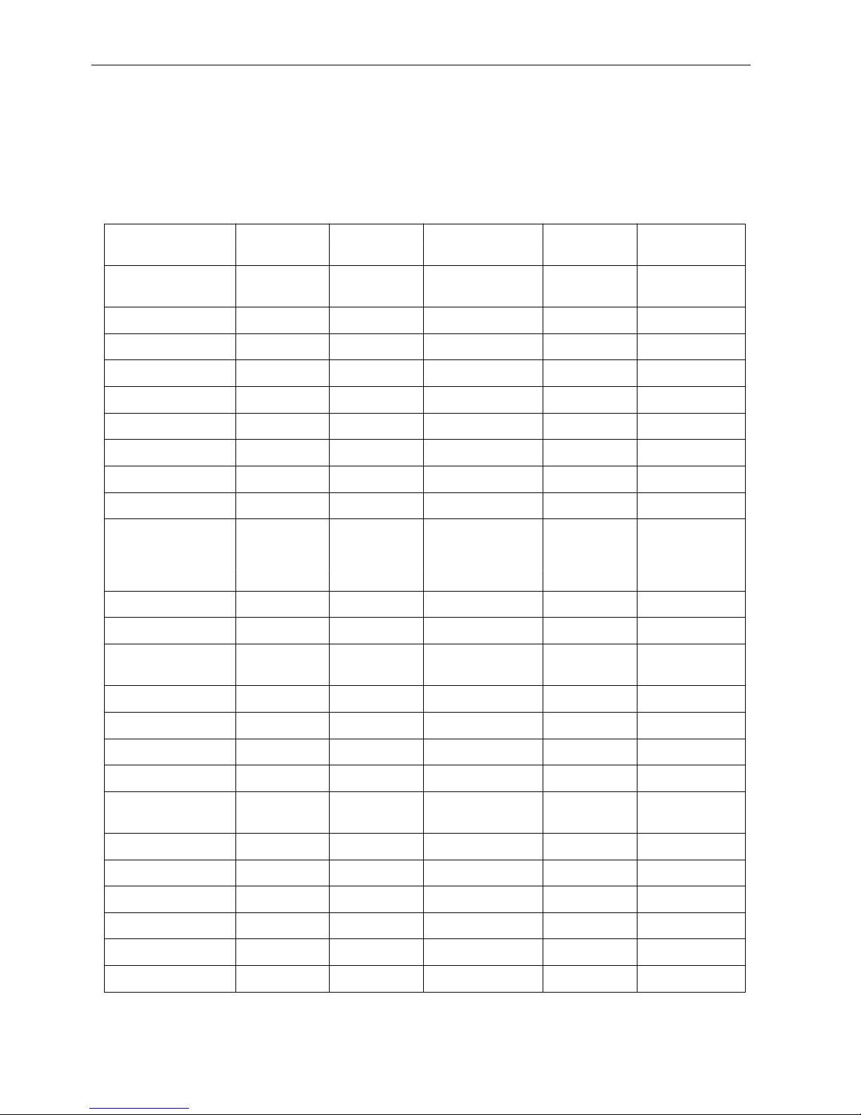
Machine Replacing Machine Model Thread Adapter cord
manuf a c t u r e r trimmi n g mode
Aisin AB62AV Lockstitch AD3XX,AD158 0 1112815
3310,EK1
Brother AB62AV Lockstitch 737-113,737-913 0 1112814
Brother AC62AV Chainstitch FD3 B257 5 1112822
Dürkopp Adler DA62AV Lockstitch 210,270 0 1112845
Global Chainstitch CB2803-56 5 1112866
Juki AB62AV Lockstitch 5550-6 14 1112816
Juki AB62AV Lockstitch 5550-7 14 1113132
Juki LU1510-7 Lockstitch 20 1113200
Kansai AC62AV Chainstitch RX 9803 5 1113130
Pegasus AC62AV Chainstitch W500/UT 5 1112821
W600/UT/MS
with/without stitch
condensing
Pegasus AB60C Backlatch 8 1113234
Pegasus Chainstitch MHG-100 24 1113267
Pfaff PF62AV Lockstitch 563,953,1050, 0 1112841
1180
Rimoldi Chainstitch F27 5 1113096
Singer SN62AV Lockstitch 212 UTT 2 1112824
Union Special US80A Lockstitch 63900AMZ 10 1112823
Union Special US80A Chainstitch 34000, 36200 4 1112865
Union Special AC62AV Chainstitch 34700 with 5 1112844
stitch lock
Union Special US80A Chainstitch CS100, FS100 4 1112905
Yamato AC62AV Chainstitch VC series 5 1112818
Yamato Chainstitch VG series 5 1113178
Yamato AB60C Backlatch ABT3 9 1112826
Yamato Backlatch ABT13, ABT17 9 1113205
Yamato Chainstitch Stitch lock 21 1113178
EFKA FP220A5911
9
2.1 Use in Accordance with Regulations
The drive is not an independently operating machine, but is designed to be incorporated into other machinery. It must not
be put into service until the machinery into which it is to be incorporated has been declared in conformity with the
provisions of the EC Directive (Appendix II, paragraph B of the Directive 89/392/EEC and supplement 91/368/EEC).
The drive has been developed and manufactured in accordance with the relevant EC standards:
EN 60204-3-1:1990 Electrical equipment of industrial machines:
Particular requir ements for industrial sewing machines, sewing units a nd sewing systems.
Operate the drive only in dry areas.
3 Scope of Supply
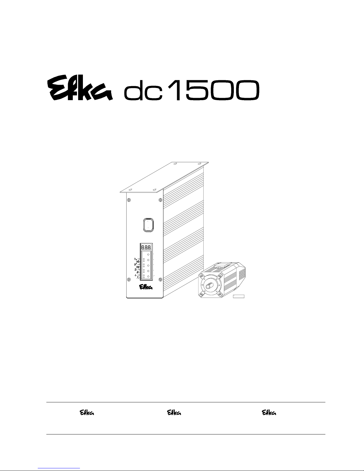
1 Direct current motor DC1500
1 Electronic control FP220A5911
- Power pack N201
1Actuator EB301A
1 Set of standard accessories B156 standard
consisting of: Plastic bag for B156
Documentation
or
1 Set of standard accessories B159 optional
consisting of: Bracket DC1500
Plastic bag for B159
Normal mount in g foo t
Belt guard, complete
Support + Mounting material
Documentation
Pulley A71-L
Adapter ring
1 Set of accessories Z53
consisting of: Pitman rod 400...700mm long
37-pin SubminD plug
Potential equalization cord
Bracket for fastening EB3..
Note
If there is no metallical contact between drive (motor) and machine head, the potential equalization cord supplied
with the unit is to be wired from the machine head to the terminal provided on the control box!
CAUTION
When selecting the installation site and the layout of the connecting cable, the Safety
Instructions in chapter 1 must be followed with no exceptions.
Particular attention should be paid to maintaining the proper distance from moving
parts!

EFKA FP220A5911
10
3.1 Special Accessories
Control panel Variocontrol V810 - part no. 5970153
Control panel Variocontrol V820 - part no. 5970154
Reflection light barrier module LSM002 - part no. 6100031
Hall sensor module HSM001 - part no. 6100032
Pulse encoder IPG001 - part no. 6100033
EFKANET interface IF232-2, complete - part no. 7900068
Adapter cord for the connection of the control to interface 232-2 - part no. 1113119
Compiler C200 (see chapter on the following page!) - part no. 1113262
Adapter cord for the connection of sockets B18 each on the SM210 stepping - part no. 1113172
motor control and on the above control (see chapter on the next page but one!)
Actuating solenoid type EM1.. (for e. g. sewing foot lifting, backtacking, etc.) - see specification
“solenoids” for
available models
Fitting piece for position transmitter - part no. 0300019
Knee switch type KN3 (pushbutton) with cord of approx. 950 mm length without plug - part no. 5870013
Adapter cord for the connection to AISIN high-speed seamer AD3XX, AD158, 3310 - part no. 1112815
and overlock machi ne EK 1
Adapter cord for the connection to BROTHER models 737-113, 737-913 - part no. 1112814
Adapter cord for the connection to BROTHER chainstitch machine model FD3 B257 - part no. 1112822
Adapter cord for the connection to BROTHER sewing machines with position sensor - part no. 1113213
incorporated in the handwheel
Adapter cord for the connection to DÜRKOPP ADLER models 210 and 270 - part no. 1112845
Adapter cord for the connection to GLOBAL model CB2803-56 - part no. 1112866
Adapter cord for the connection to JUKI high-speed seamer with index -6 - part no. 1112816
Adapter cord for the connection to JUKI high-speed seamer with index -7 - part no. 1113132
Adapter cord for the connection to JUKI lockstitch machines with position sensor - part no. 1113157
incorporated in the handwheel
Adapter cord for the connection to JUKI high-speed seamer model LU1510-7 - part no. 1113200
Adapter cord for the connection to KANSAI machine model RX 9803 - part no. 1113130
Adapter cord for the connection to PEGASUS models W500/UT, W600/UT/MS - part no. 1112821
with or without stitch condensing
Adapter cord for the connection to PEGASUS backlatch machine - part no. 1113234
Adapter cord for the connection to PEGASUS chainstitch machine MHG-100 - part no. 1113267
Adapter cord for the connection to PFAFF models 563, 953, 1050, 1180 - part no. 1112841
Adapter cord for the connection to RIMOLDI model F27 - part no. 1113096
Adapter cord for the connection to SINGER models 211, 212U, 212UTT and 591 - part no. 1112824
Adapter cord for the connection to UNION SPECIAL lockstitch machine model - part no. 1112823
63900AMZ (as a replacement for the US80A)
Adapter cord for the connection to UNION SPECIAL model 34700 with stitch lock - part no. 1112844
Adapter cord for the connection to UNION SPECIAL models 34000 and 36200 - part no. 1112865
(as a replacement for the US80A)
Adapter cord for the connection to UNION SPECIAL models CS100 and FS100 - part no. 1112905
Adapter cord for the connection to YAMATO VC series chainstitch machines - part no. 1112818
Adapter cord for the connection to YAMATO VG series chainstitch machines - part no. 1113178
Adapter cord for the connection to YAMATO backlatch machine ABT3 - part no. 1112826
Adapter cord for the connection to YAMATO backlatch machines ABT13, ABT17 - part no. 1113205
Extension c able approx. 1000 mm long for commutation transmitter DC15.. - part no. 1113151
Extension c able approx. 1000 mm long for DC15.. line - part no. 1113150
Adapter cord for the connection of both light barrier module and Hall sensor module - part no. 1113229
or EFKANET
Mounting kit for DC1500 on PEGASUS model W600 - part no. 1113125
Mounting kit for DC1500 on PEGASUS Ex/Ext - part no. 1113126
Undertable mounting kit for DC15.. - part no. 1113235
Sewing light transformer - please indicate
line voltage and
sewing light voltage
(6,3V or 12V)
9-contact SubminD male connector - part no. 0504135
9-contact SubminD male connector - part no. 0504136
Half-shell housing for 9-contact SubminD - part no. 0101523
37-pin SubminD male connector, complete - part no. 1112900
Single pins for 37-pin SubminD with strand of 5cm length - part no. 1112899

EFKA FP220A5911
11
4 Use of the C200 Compiler
The Efka C200 Compiler is a software tool for the programming of functions on the FP220A control, with which the user
can program a variety of additional user-defined functions.
The compiler provides the following basic functions:
! predetermined functions which are integrated by means of a system file
! approx. 2kB for user programs and data
!
error management routine with automatic error marking
! loader for program storing in the control
! a multi-tasking time sharing mechanism
The FP220A control (socket B18) and the computer (socket com1) are connected by means of interface IF232-2.
Set of special C200 compiler accessories consisting of: order no. 1113262
! C200 Compiler Software CD-ROM
!
C200 Compiler User Manual
! EFKANET IF232-2 Interface
See C200 Compiler user manual for more information on programming and use of control commands!
EFKA FP220A5911
12
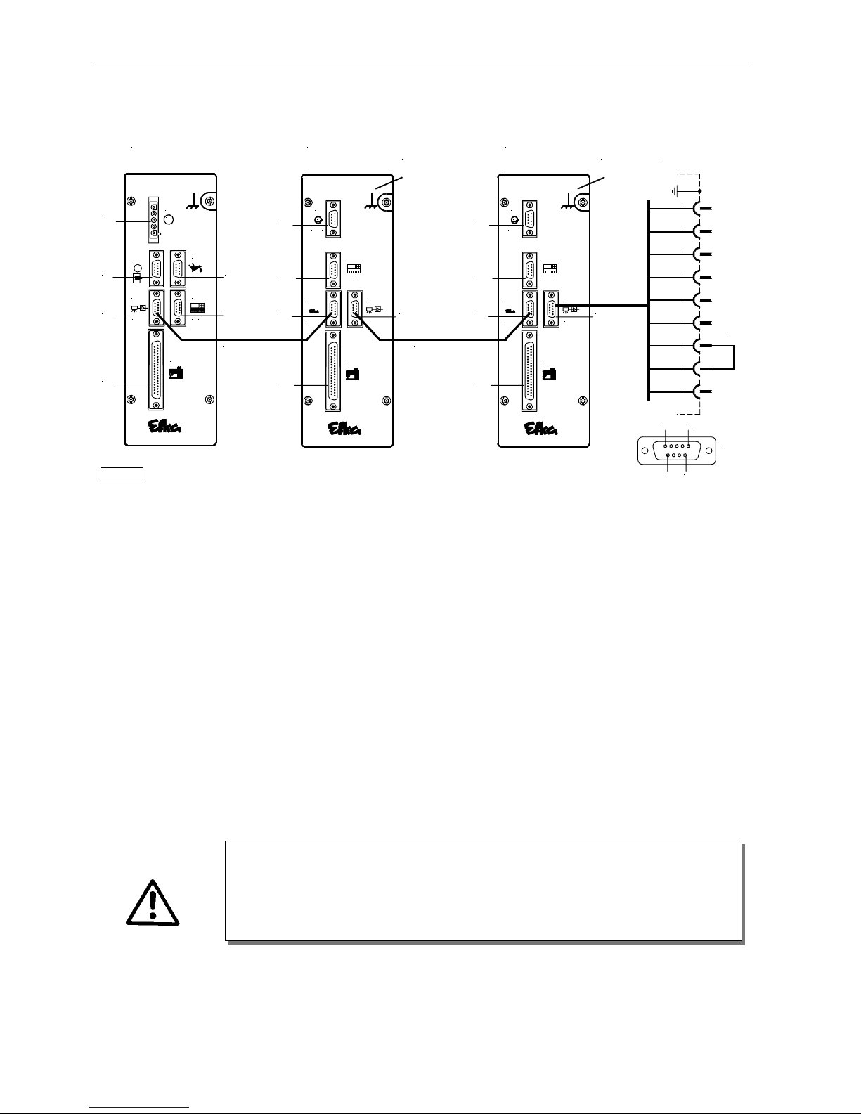
5 Connection of Stepping Motor Controls to the FP220A Control
*) Front view of the socket (component side) and/or rear view of the plug (soldering side)
5.1 SM210A Control Settings for Operating the FP220A Control
! Parameter 290 = 10 In mode 10, the SM210A control operates as slave.
! Parameter 272 = 2 #2 = SCI stepping motor control address. All additional controls have higher addresses
(..#3, #4, etc.)
! Parameter 270 = 560 Baud rate
! Parameter 401 = 1 Immediate storing of the settings in the EEPROM.
5.2 FP220A Control Settings
!
Parameter 401 = 1 Immediate storing of the settings in the EEPROM.
ATTENTION
Turn on the FP220A / FP320A control together with the connected SM210A controls
by means of one mains switch.
Place a jumper between pin 2 and pin 3 on socket B19 of the last SM210A stepping
motor control.
Nr. 1113172
B776
B80B2
Nr. 1113172
LSM ...
KL2484
B18
B18
ST2
E B ...
B776
ST2
V8 . .
B776
B18
control
B18
ST1
V8
ST1
B19
L S M ...
..
B19
M
FP220A
B2
B41
B41
M
B80
SM210A
M
B5
1mot
B5
B776
#2
B776
B18
control
B18
ST1
V8
ST1
B19
L S M ...
..
B19
Br.
591
6
(*)
SUB - D- 9
321 54
SM210A
M
B5
1mot
B5
B776
#3
B19
6 987
EFKA FP220A5911
13
6 Control Operation without Control Panel
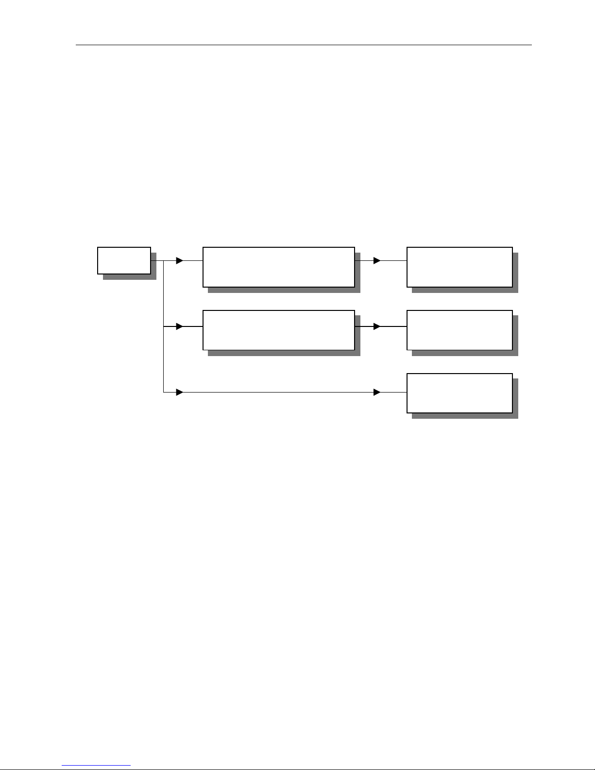
6.1 Access Authorization upon Command Input
In order to prevent unintentional changes of preset functions the command input is distributed at variou s levels.
The following persons have access: - the supplier to the highest and all subo rdinate levels by means of a code
number
- the technician to the next lower and all subordinate levels by means of a code
- number
- the operator to the lowest level without code number
ACaCCallufruf
Call-up
Supplier: Code number for
control 311 or
control panel 3112
Supplier Level
200 series of
parameter numbers
Technician: Code number for
control 190 or
control panel 1907
Technician Level
100 series of
parameter numbers
Operator Level
EFKA FP220A5911
14
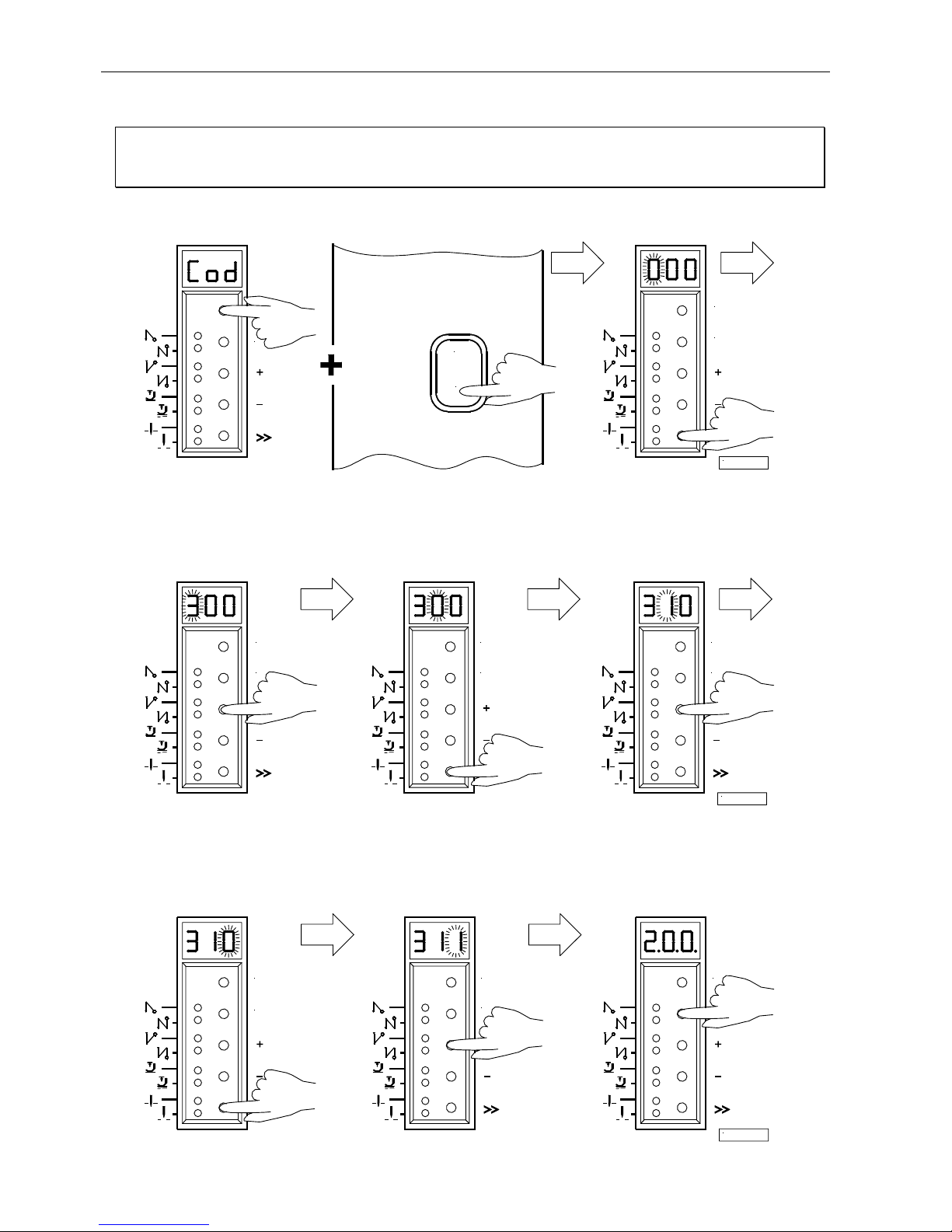
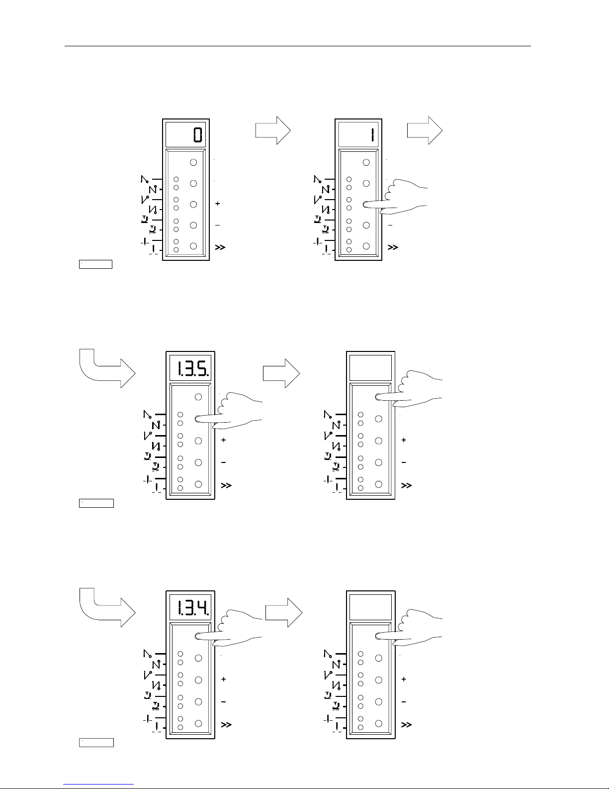
6.2 Programming the Code Number
Note
The parameter numbers in the illustrations below serve as examples and may not be available in all program versions.
In this case, the display shows the next higher parameter number. See List of Parameters.
1.
Press the P key and turn power on
2.
Press the >> key (1st digit blinks)
3.
Press the + or – key to select
4.
Press the >> key
5.
Press the + or – key to select
the 1st digit (2nd digit blinks) the 2nd digit
Technician level " Code no. 190
Supplier level " Code no. 311
6.
Press the >> key
7.
Press the + or – key to
8.
Press the E key; the parameter
(3rd digit blinks) select the 3rd digit number is displayed, which is
indicated by points between the
digits.
E
0
I
1/K L2316
P
E
E
P
E
P
2/K L2317
E
P
P
E
P
E
3/K L2318
P
EFKA FP220A5911
15
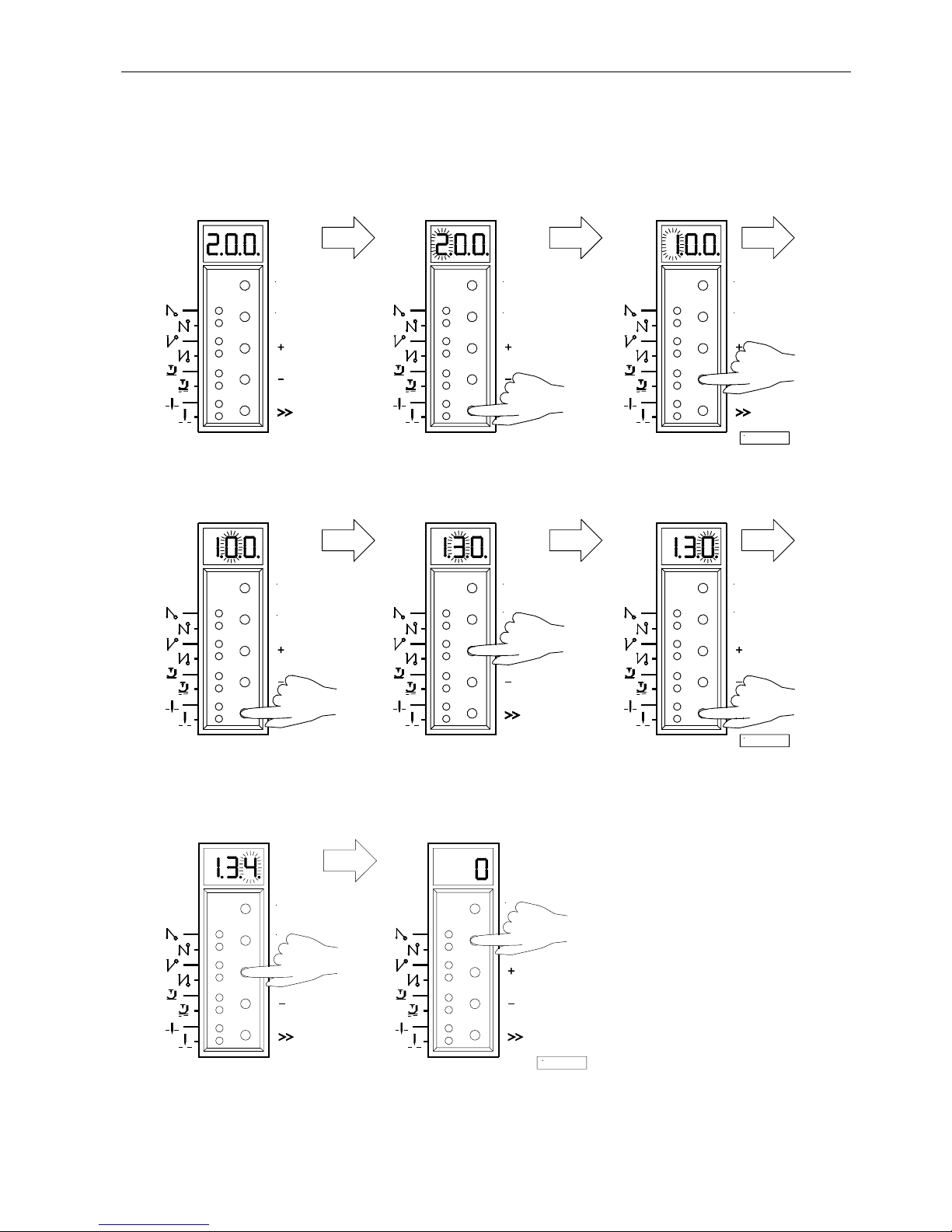
6.3 Parameter Selection
6.3.1 Direct Selection
1.
After code number input at the
2.
Press the >> key
3.
Press the + or – key to select
programming level (1st digit blinks) the 1st digit
4.
Press the >> key
5.
Press the + or – key to select
6.
Press the >> key
(2nd digit blinks) the 2nd digit (3rd digit blinks)
7.
Press the + or – key to select
8.
Press the E key; the parameter
the 3rd digit value is displayed. There are no
points between the digits.
P
E
P
E
4/K L2319
P
E
P
E
P
E
5/K L2320
P
E
P
E
6/K L2321
P
EFKA FP220A5911
16
6.3.2 Changing Parameter Values
1.
Display after parameter value selection
2.
Change the parameter value by pressing the
+ or - key
Option 1
Press the E key. The next Press the P key. Exit programming.
parameter number is displayed. The changed parameter values will be saved
when you start sewing again!
Option 2
Press the P key. The same Press the P key. Exit programming.
parameter number is displayed. The changed parameter values will be saved
when you start sewing again!
7/K L2322
P
E
P
E
8/K L2323
P
E
9/K L2324
E E
EFKA FP220A5911
17
6.3.3 Parameter Selection with the +/- Keys
1.
After code number input at the
2.
Select the next parameter by pressing the + key
programming level
3.
Select the previous parameter by
4.
After pressing the E key, the
pressing the - key parameter value is displayed
These values are saved when you start sewing. They remain in effect even after turning the machine off!
Using parameter 401 is another possibility for immediate storage without having to start sewing.
6.3.4 Immediate Storage of All Changed Data
Functions Parameter
Immediate storage of all changed data (EEP) 401
! Input code number 3112 after power On " Taste E betätigen
!
Input parameter 401 " Taste E betätigen
! Set display from 0 to1 " Taste E oder P betätigen
!
All data are stored!
10/K L2325
P
E
P
E
11/K L2326
P
E
P
EFKA FP220A5911
18
6.4 Changing All Parameter Values at the Operator Level
All parameter values at the operator level can be changed without code number input (see List of Parameters).
!
Press the P key " The first parameter number will be displayed
! Press the E key " The parameter value will be displayed
!
Press the +/- keys " The parameter value will be changed
! Press the E key " The next parameter will be displayed
! Press the E key " The parameter value will be displayed
! Press the +/- keys " The parameter value will be changed
etc.
!
Press the P key t wice " Exit programming at the operator level
6.5 Function Switchover
Switchable functions can be changed by pressing the appropriate key. The switching state is indicated by light emjtting
diodes (LED). See above illustration!
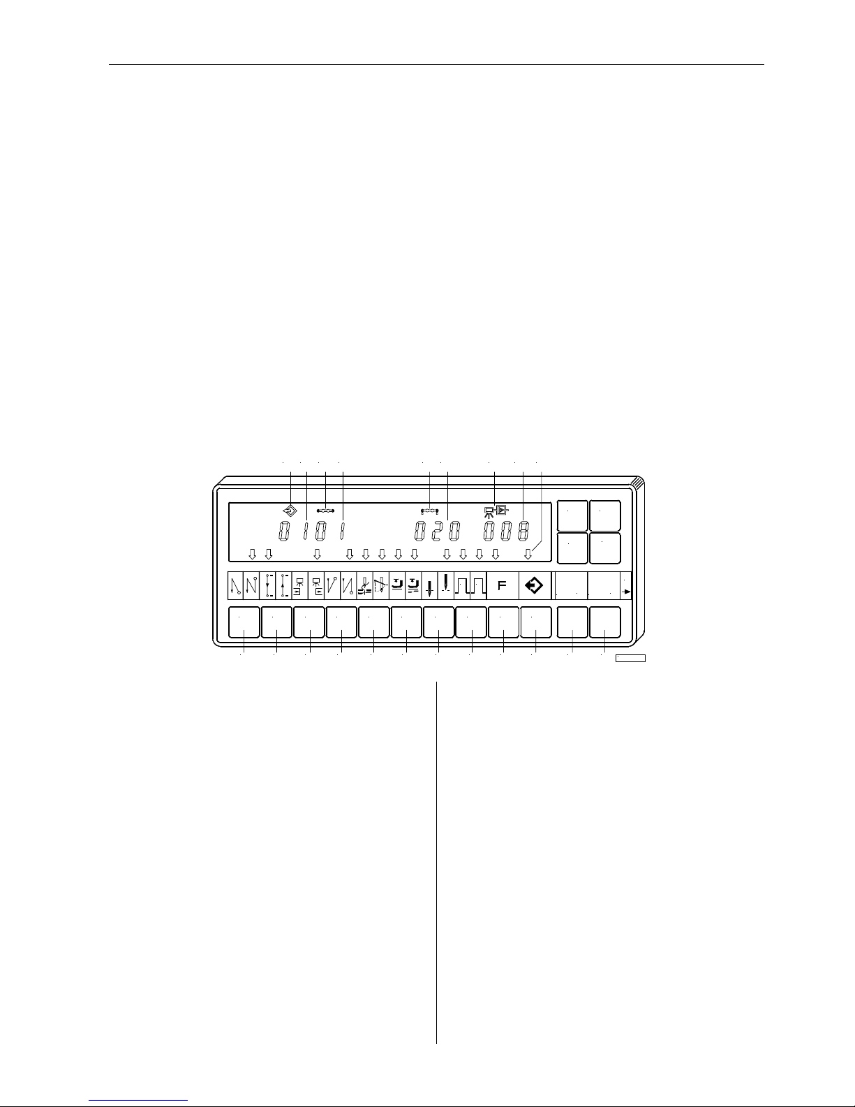
Table: Assignment of functions to keys and LEDs
Function Key LED number
Single start backtack / Chain suction at the start of the seam E (S2) 1 = on 2 = off
Double start backtack / Chain suction at the seam end E 1 = off 2 = on
Chain suction at the start of the seam / seam end E 1 = on 2 = on
Start backtack Off / Chain suction Off E 1 = off 2 = off
Single end backtack / Tape cutter at the start of the seam + (S3) 3 = on 4 = off
Double end backtack / Tape cutter at the seam end + 3 = off 4 = on
Tape cutter at the start of the seam / seam end + 3 = on 4 = on
End backtack Off / Tape cutter Off + 3 = off 4 = off
Sewing foot lift at stop in the seam (automatic) - (S4) 5 = on 6 = off
Sewing foot lift at the seam end (automatic) - 5 = off 6 = on
Sewing foot lift at stop in the seam and at the seam end (automatic) - 5 = on 6 = on
Sewing foot lift (automatic) Off - 5 = off 6 = off
Basic position down (position 1) >> (S5) 7 = on 8 = off
Basic position up (position 2) >> 7 = off 8 = on
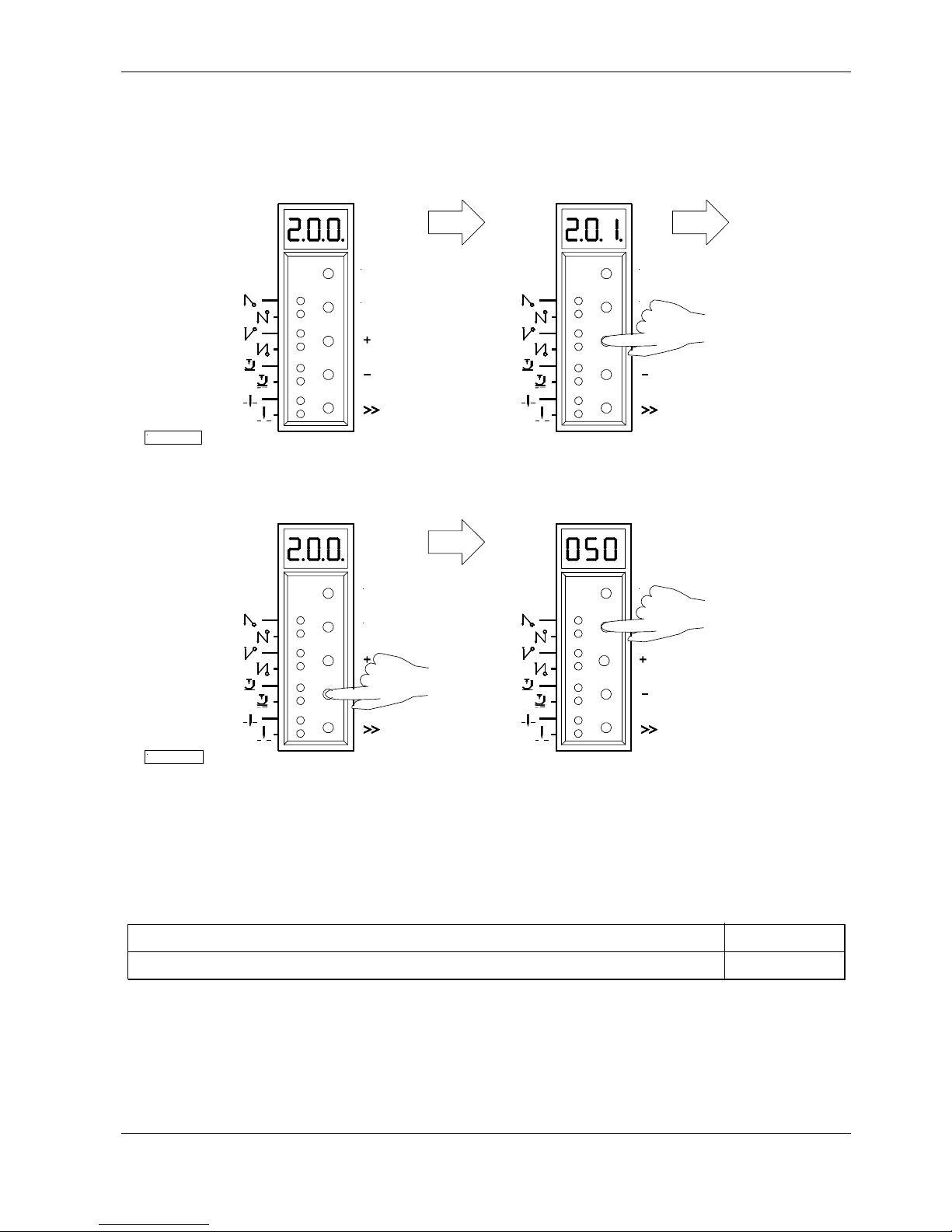
6.6 Direct Input of Maximum Speed Limitation without Control Panel
The maximum speed of the machine must be limited to the specific level according to the application. Do the setting at the
operator level on the control by means of the +/- keys during operation or at intermediate machine stop . This function is
blocked at the start of the seam or after the seam end. The actual value shown on the display must be multiplied by 10.
When using a control panel, the full speed value is displayed. See also chapter 7.4!
Example:
The value 330 on the control display corresponds to a speed of
3300 RPM.
Important! If the speed is changed, it is saved only after trimming
and when you start sewing again.
LED3
LED4
LED5
LED6
LED7
LED8
LED2
LED1
S1
S5
S2
S3
S4
13/KL2328a
P
E
LED7
LED8
LED1
LED2
LED3
LED4
LED5
LED6
S1
S4
S3
S2
S5
12/KL2327a
P
E
EFKA FP220A5911
19
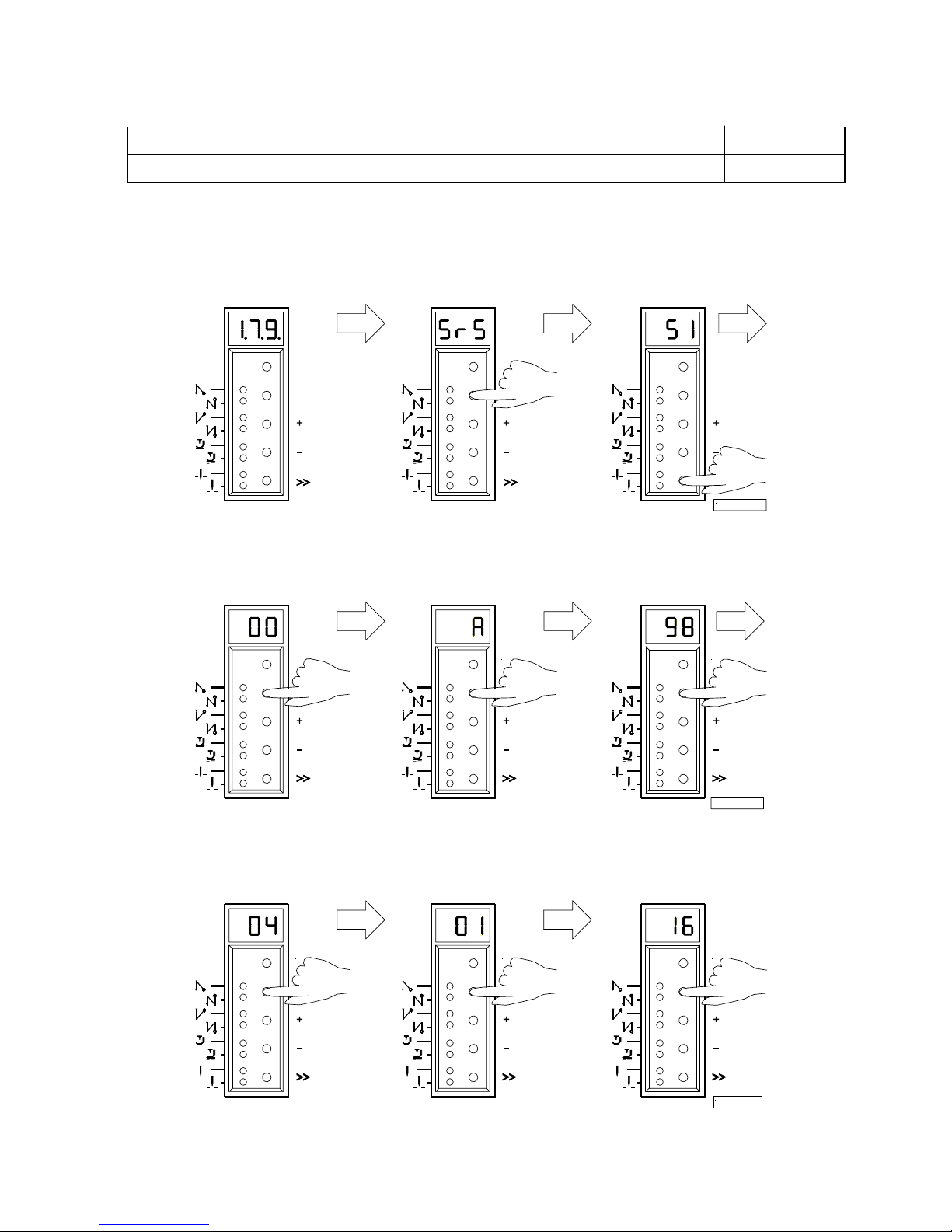
6.7 Program Identification on the Control
Function without control panel Parameter
Program number, modification index and identification number display 179
After having selected parameter 179, the following information is displayed in succession:
1.
Select parameter 179.
2.
Press the E key.
3.
Press the >> key.
Abbreviation Sr5 is displayed. The first 2 digits of the
program number are displayed.
4.
Press the E key.
5.
Press the E key.
6.
Press the E key.
The second 2 digits of the The program modification The identification number
program number are displayed. index is displayed. digits 1 and 2 are displayed.
7.
Press the E key.
8.
Press the E key.
9.
Press the E key.
The identification number The identification number The identification number
digits 3 and 4 are displayed. digits 5 and 6 are displayed. digits 7 and 8 are displayed.
The routine is repeated after pressing the E key. Exit the routine after pressing the P key once. The next parameter number
is displayed. Exit programming after pressing the P key. The drive is again ready for sewing.
P
E
P
14/K L2329a
P
E
P P P
15/K L2330a
P P
17/K L2361
P
EFKA FP220A5911
20
7 Control Operation with Control Panel
7.1 Operation of the V810 Control Panel
7.1.1 Code Number Input on the V810 Control Panel
Example: Technician level CODE number selection on the V810 control panel
TURN POWER OFF
+
TURN POWER ON. First digit blinks ! "
Press the + or – key to select the first digit !
"
Press the >> key !
Second digit blinks ! "
Press the + or – key to select the second digit !
"
Press the >> key twice !
Fourth digit blinks ! "
Press the + or – key to select the fourth digit!
"
If the CODE number is correct, the first
PARAMETER number at the selected level "
is displayed !
7.1.2 Parameter Input at the Operator Level on the V810 Control Panel
Example: CODE number has not been input !
TURN POWER ON ! "
First parameter at the operator level is
displayed. "
Second parameter at the operator level is
displayed. The next or previous parameter "
can be called by pressing the +/- keys.
Parameter value is displayed ! "
Change parameter value by pressing the
+/- keys. "
Parameter value is entered.
Display advances to the next parameter. "
Press the + key several times until the "
desired parameter is displayed !
Parameter value is displayed ! "
Technician Level Code Number => 1907 and Supplier Level Code Number => 3112
P
C – 0 0 0 0
+
-
C – 1 0 0 0
» C – 1 0 0 0
+
- C – 1 9 0 0
» » C – 1 9 0 0
+
- C – 1 9 0 7
E
F – 1 0 0
F P 2 2 0 A
P
F – 0 0 0
+
F – 0 0 1
E
0 0 3
+
X X X
E
F – 0 0 2
+
F – 0 0 9
E
0
EFKA FP220A5911
21
New parameter value is displayed ! "
Next parameter is displayed ! "
or
Exit programming ! "
These values are saved when you start sewing. They remain in effect even after turning the machine off!
Using parameter 401 is another possibility for immediate storage without having to start sewing.
7.1.3 Parameter Input at the Technician/Supplier Level on the V810 Control Panel
Example: After CODE number input at the technician level.
After CODE number input, the first
PARAMETER number is displayed! "
Press the + key ! The next
parameter number is displayed ! "
Press the E key !
The parameter value is displayed ! "
Change the parameter value ! "
Parameter value is entered.
Display advances to the next parameter. "
or
Parameter value is entered.
The actual PARAMETER number is displayed! "
or
Press the P key twice !
Exit programming ! "
These values are saved when you start sewing. They remain in effect even after turning the machine off!
Using parameter 401 is another possibility for immediate storage without having to start sewing.
7.2 V820 Control Panel Operation
7.2.1 Code Number Input on the V820 Control Panel
Example: Technician level CODE number selection on the V820 control panel
TURN POWER OFF !
+
TURN POWER ON ! "
Input CODE number ! "
+
1
Note! The parameter number can also be selected directly, like the code number!
F – 1 0 0
+
F – 1 1 0
E
0 1 8 0
+
- 0 X X X
E
F – 0 1 3
P
F P 2 2 0 A
E
F – 1 1 1
P
F - 1 1 0
P
P
F P 2 2 0 A
Technician Level Code Number => 1907 and Supplier Level Code Number => 3112
P
C–0000
1 9
C–1907
0
7
EFKA FP220A5911
22
If CODE number is incorrect,
repeat input ! "
If CODE number is correct,
the first PARAMETER number at the "
selected level is displayed.
7.2.2 Parameter Input at the Operator Level on the V820 Control Panel
Example: CODE number has not been input !
TURN POWER ON ! "
Display shows no reading ! "
First parameter at the operator level
is displayed. PARAMETER number "
is not displayed.
Change the parameter value ! "
Parameter value is entered.
Display advances to the next parameter. "
or
Exit programming ! "
7.2.3 Parameter Input at the Technician/Supplier Level on the V820 Control Panel
Example: After CODE number input at the technician level.
After CODE number input, the first "
PARAMETER number is displayed.
The most significant digi t of the
PARAMETER number blinks. "
Input desired PARAMETER
number! "
If PARAMETER number is incorrect,
repeat input! "
If PARAMETER number is correct "
Change the parameter value! "
Parameter value is entered.
Display advances to the next parameter. "
or
Parameter value is entered.
A new PARAMETER number can be "
selected.
or
Press the P key twice.
Exit programming! "
These values are saved when you start sewing. They remain in effect even after turning the machine off!
Using parameter 401 is another possibility for immediate storage without having to start sewing.
E
C–0000 InFo F1
E
F–100
4000 FP220A
E
c2 003
E
c1 003
P
4000 FP220A
P
+
-
c2 XXX
F-100
E
F-100
1 1
F-110
0
E
F–XXX InFo F1
E
F–110 n1 180
E
F-111 n2- 4000
P
F-XXX
+
-
F-110 n1 XXX
P
P
4000 FP220A
EFKA FP220A5911
23
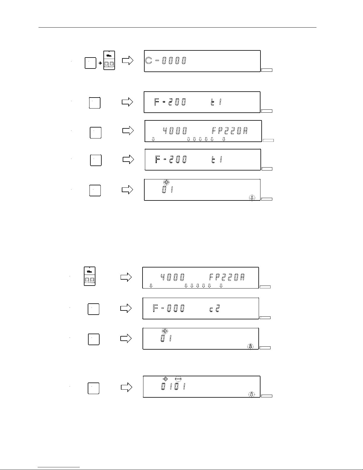
7.3 Program Identification
Function with control panel Parameter
Program number, modification index and identification number display 179
Display example parameter 179 on the V810 control panel:
! Select parameter 179!
!
Press the E key " Sr5 [°] is displayed
! Press the >> key " e. g. 5911A is displayed (Program number with index)
! Press the E key " e. g. 010823 is displayed (1st part of identification number)
!
Press the E key " e. g. 15 is displayed (2nd part of identification number)
! Press the P key twic e " FP220A is displayed (Sewing process can be started)
Display example parameter 179 on the V820 control panel:
! Select parameter 179!
!
Press the E key " F-179 Sr5 [°] is displayed
! Press the >> key " e. g. 5911A is displayed (Program number with index)
! Press the E key " e. g. 01082315 is displayed (Identification number)
!
Press the P key t wice " FP220A is displayed (Sewing process can be started)
7.4 Direct Input of Maximum Speed Limitation (DED) with Control Panel
The maximum speed of the machine must be limited to the specific level according to the application. Do the setting at the
operator level by means of the +/- keys at any time. The actual value is shown on the display. The speed setting range is
between parameter 111 (upper limit) and parameter 121 (lower limit).
7.4.1 Setting on the V810 Control Panel
Type designation is displayed "
Maximum spe ed is displa yed
(reading remains on for max. 5 seconds) "
Change the value;
e. g. press the – key 8 times ! "
After approx. 5 seconds the display shows "
7.4.2 Setting on the V820 Control Panel
Actual display value, in the direct mode
Maximum speed and type designation are displayed "
Change the maximum speed value;
e. g. press the – key 8 times ! "
F P 2 2 0 A
+
4 0 0 0
+
- 3 2 0 0
F P 2 2 0 A
4000 FP220A
+
- 3200 FP220A
Note
Changing the setting of the maximum speed limitation also affects the start backtack, end backtack and stitch
counting spee ds.
EFKA FP220A5911
24
7.5 Keys for Background Information (HIT) with V820
(key assignment see figure on the last page)
For fast operator information, the values of functions switched on by means of the 1, 2, 3, 4 and 9 keys are displayed on the
control panel for approx. 3 seconds. During this time, the respective values can be varied directly by pressing the + or key.
7.5.1 Example of HIT
Increase stitch-count seam section from 20 stitches to 25 stitches.
Stitch-count function (2 key) is off.
Display after power on "
↓↓↓↓
Press the 2 key br iefly ! Lefthand arrow
and stitch-count function are on "
Press the + key ! "
Increase the number of stitches from 20 to 25 !
Display after approx. 3 seconds "
Stitch-count function (2 key ) is already on.
Display after power on "
↓↓↓↓
Press the 2 key for at least 1 second!
Lefthand arrow goes off momentarily; "
stitch-count function is on
Press the + key ! "
Increase the number of stitches from 20 to 25 !
Display after approx. 3 seconds "
These values are saved when you start sewing. They remain in effect even after turning the machine off!
Using parameter 401 is another possibility for immediate storage without having to start sewing.
Function key F
Various parameters, eve n higher-level parameters, can be s witched on or off by pressing the funct ion key (9 key).
The following functions may be assigned to the function key:
1. Softstart ON/OFF
2. Ornamental backtack ON/OFF
3. Se wing start blocked with light barrier uncovered ON/OFF
4.
Unlocking the chain ON/OFF
5. Signals A1 and/or A2 On/Off with slide-in strips 1...4 (lefthand arrow = A1, righthand arrow = A2)
The key assignment can be changed as follows:
Display after power on "
Press the P key! "
Note
The following functions are possible only with the V820 control panel!
4000 FP220A
2 Stc 020
+
Stc 025
4000 FP220A
2 Stc 020
+
Stc 025
4000 FP220A
4000 FP220A
P
4000 FP220A
EFKA FP220A5911
25
Press the E key! "
Press the E key several times until the
letter symbol –F– appears ! "
(ornamental backtack On/Off)
Press the – key! "
(softstart On/Off)
Press the P key! "
The assignment is completed.
The number of softstart stitches can be changed as follows:
Example: change number of stitches from 1 to 3 (softstart function (9 key) is off).
Press the 9 key bri efly !
The arrow above the key lights up "
(softstart function is On)
Press the + key ! "
Number of stitches increases.
Display after 3 seconds "
Example: change number of stitches from 1 to 3 (softstart function (9 key) is already on).
Press the 9 key for at least 1 sec. !
The arrow above the key goes off momentarily "
(softstart function is On)
Press the + key ! "
Number of stitches increases.
Display after 3 seconds "
These values are saved when you start sewing. They remain in effect even after turning the machine off!
Using parameter 401 is another possibility for immediate storage without having to start sewing.
7.5.2 Further Functions of the V810/V820 Control Panels
! Press the >> key " The most significant digit blinks.
! Press the +/- key briefly " The blinking digit changes by ±1.
! Keep the +/- pressed down " The blinking digit keeps changing its value, as long as the key is
pressed down.
!
Press the >> key once more " The next digit bl i nks.
!
Press the +/- key as above!
!
Press the E key " The setting is completed.
With the code number and parameter number there is no carry over when changing from 0 to 9 or vice versa. Parameter
values are, however, carried over. Therefore, you can use the +/- keys to change the value beween the minimum and
maximum va lue.
If the value change is significant, it is better to use the >> key. If the value change is insignificant, use the +/- keys.
For setting the minimum or maximum value, select the most significant digit by means of the >> ke y. The n keep pre ssing
the – key for the minimum or the + key for the maxi mu m va lue.
The above description is applicable to both control panels, V810 and V820. Direct input of values is possible with the V820
using the 0...9 keys.
E
c2 002
E
-F- 2
- -F- 1
P
4000 FP220A
9 SSc 001
+
SSc 003
4000 FP220A
9 SSc 001
+
SSc 003
4000 FP220A
EFKA FP220A5911
26
7.5.3 Special Functions of the V820 Control Panel
Select parameter 200 "
Press the E key. "
The set value is displayed.
Press the 0 key three times. "
The minimu m value is displayed.
Press the 9 key three times. "
The maximum value is disp layed.
2 0
F-200
0
E
F–200 t1 050
0 0
F-200 t1 000
0
9 9
F-200 t1 500
9
EFKA FP220A5911
27
7.6 Programming of Seams (TEACH IN)
! A maximum of 99 patterns with a total of 99 seams can be programmed, i. e. 1 pattern with 99 seams each or 99
patterns with 1 seam each. In between, all combinations are possible.
! Programming is possible with or without code number.
!
The functions “start backtack”, “end backtack”, “stitch counting”, “light barrier”, “thread trimmer”, “sewing foot lift”
and “needle positions” can be assigned individually to each seam.
!
The functions of signals A1 and A2 can also be assigned to each seam, on condition that slide-in strip 6 , 8, 9, 10 has
been inserted into the V820 control panel and activated by means of the respective parameter 292.
! The stitches for start and end backtack and stitch counting as well as the compensating stitches for the light barrier
function can be programmed individually for each seam section.
! Several counted seam sections can be linked (9 key).
Attention!
The “TEACH IN“ function has been changed as compared to the 62 and 82 type series!
Seams and/or patterns can be added by pressing the INSERT F1 key or erased by pressing the DELETE F2 key. Before
programming new patterns and/or seams it is advisable to erase previously saved patterns and/or seams by pressing the
DELETE F2 key according to chapter “Deleting a Seam or Pattern“. If patterns or seams are to be inserted between
existing ones, press the INSERT F1 key according to chapter “Inserting a Seam or Pattern“.
Example: 3 patterns are in the memory. Delete the 2nd pattern b y pressin g the DELETE F2 key. The 3rd pattern takes the
place of the 2nd pattern. A new 2nd pattern can be intalled by pressing the INSERT F1 key. The pattern in 2nd place will
go back to being pattern no. 3.
If patterns and/or seams are only to be added, proceed as described in the following chapters.
The figure below shows all the functions assigned to programming of seams TEACH IN.
1 = Single start backtack On (lefthand arrow)
Double start backtack On (righthand arrow)
Start backtack Off
2 =Counted seam forward On (lefthand arrow)
Counted seam backward On (righthand arrow)
Counted seam Off
3 = Light barrier uncovered/covered On (lefthand arrow)
Light barrier covered/uncovered On (righthand arrow)
Light barrier Off
4 = Single end backtack On (lefthand arrow)
Double end backtack On (righthand arrow)
End backtack Off
5 = Thread trimmer On (lefthand arrow)
Thread wiper On (righthand arrow)
Thread trimmer and thread wiper On (both arrows)
Thread trimmer and thread wiper Off
6 =Sewing foot in the seam On (lefthand arrow)
Sewing foot after seam end On (righthand arrow)
Sewing foot in the seam and after seam end On
(both arrows)
Sewing foot Off
7 = Basic position down (lefthand arrow)
Basic position up (righthand arrow)
8 = Signal A1 On (lefthand arrow)
Signal A2 On (righthand ar row)
Signal A1 and A2 On (both arrows)
Signal A1 and A2 Off
9 = Switching from one seam to the next On
(lefthand arrow)
Switching from one seam to the next Off
10 = Programmed seams TEACH IN On (lefthand arrow)
Programmed seams TEACH IN Off
11 = Program symbol
12 = Display of program number
13 = Seam symbol
14 = Display of seam number
15 = Symbol for number of stitches of a seam
16 = Display of number of stitches
17 = Light barrier symbol
18 = Display of light barrier compensating stitches
19 = Arrow for TEACH IN
A=INSERT " Insert seams or patterns
B=DELETE " Delete seams or patterns
7
16
7
21
1 2
3 4435 6
65
13 141211 15
B
E
DELETE
8 9
98
1 2
0
A10
INSERT
F1
1817 19
P
+
6
KL2369
F2
-
EFKA FP220A5911
28
7.6.1 Programming after Code Number Input
!
Input code number by means of the 0...9 keys.
!
Activate programming of seams TEACH IN by means of the 0 key / Display of pattern number.
Select the next pattern number by means of the + key, in case the actual pattern is already programmed.
Continue the programming of seams as described i n the next chapter “Pro gramming wit hout Code Number Input”
from item 4.) onwards.
7.6.2 Programming without Code Number Input
! Activate programming of seams TEACH IN by means of the 0 key / Display of pattern number.
Select the next pattern number by means of the + key, in case the actual pattern is already programmed.
0 I
1.) P
KL2370
E2.)
KL2371
4.) E
KL2373
5.) 0
KL2374
2.) P
KL2376
3.) 0
KL2377
4.) E
KL2378
3.)
P
KL2468
1.)
I0
KL2469
 Loading...