

Efka AB620A, AB611A, AB600A Instructions For Use Manual
- Variocontrol V860
AB600A
AB611A
AB620A
Instructions for changing
the circuit boards
Nr.402453 english
(for german language and colored illustration use downloadlink)
www.efka.net/Downloads/Andere/Changing circuit boards AB6xxx
FRANKL & KIRCHNER EFKA OF AMERICA INC. EFKA ELECTRONIC MOTORS
GMBH & CO KG SINGAPORE PTE. LTD.


Contents
1 Important instructions ............................................................................................................. 4
2 Scope of Supply ....................................................................................................................... 5
3 Changing the circuit boards AB600A .................................................................................. 5
3.1 Required tools .................................................................................................................. 5
3.2 Removing the control housing .......................................................................................... 5
3.3 Removing the circuit board ............................................................................................... 7
3.4 Installation oft he circuit board ....................................................................................... 10
3.5 Installing the housing ..................................................................................................... 15
4 Changing the Circuit boards AB611A & AB620A ........................................................ 16
4.1 Required tools ................................................................................................................ 16
4.2 Removing the Control housing ........................................................................................ 16
4.3 Removing the line filter cicruit board .............................................................................. 19
4.4 Removing the main cicruit board .................................................................................... 23
4.5 Installation oft he main cicruit board .............................................................................. 25
4.6 Installation of the line filter board .................................................................................. 30
4.7 Installing the housing ..................................................................................................... 33
- AB600A /AB611A /AB620A
ATTENTION!
The controls must be completely disconnected
from power during the entire work!
ATTENTION!
ALL work on the controls must be performed in powerless condition!
Safety instructions warn of dangers and help prevent injuries!
Important Notes
For current versions of the Instructions for Use and Lists of Parameters, necessary for operating
EFKA drives in accordance with regulations, please refer to the EFKA web site www.efka.net,
page ”Downloads“.
On our web site you will also find the following supplementary instructions for this control:
General instructions for use and programming
Use with USB Memory Stick
Adapter cords
1 Important instructions
Warranty and liability
Warranty and liability claims for personal and property damage are excluded if they result due to one
or more of the following causes:
o Improper use of the controls
o Improper assembly and commissioning
o Not following instructions in the assembly instructions
o Independent constructional changes of the controls
o Insufficient maintenance and repair measures
4 | P a g e
- AB600A /AB611A /AB620A
2 Scope of Supply
Repair set for circuit board -AB600A -Order- Nr. 311 4051
Thermal Compound Keratherm KP97 1ml - Order- Nr. 150 5077
Repair set for main circuit board -AB611A - Order- Nr. 311 4013
Repair set for main circuit board -AB620A - Order- Nr. 311 4123
Netfiltert circuit board -AB611A & AB620A - Order- Nr. 311 3832
Instructions for changing the circuit boards - Order- Nr. 020 7288
3 Changing the circuit boards AB600A
3.1 Required tools
1x Torx screwdriver T 20
1x Torx screwdriver T 10
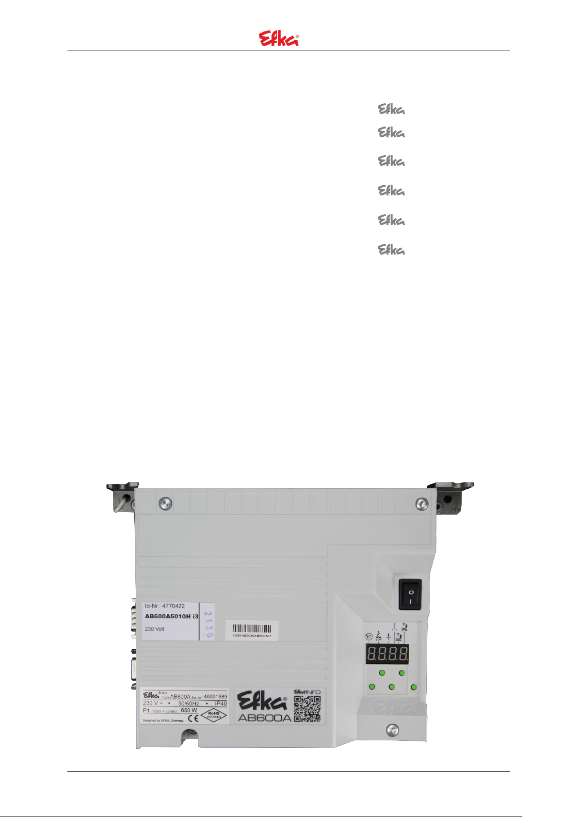
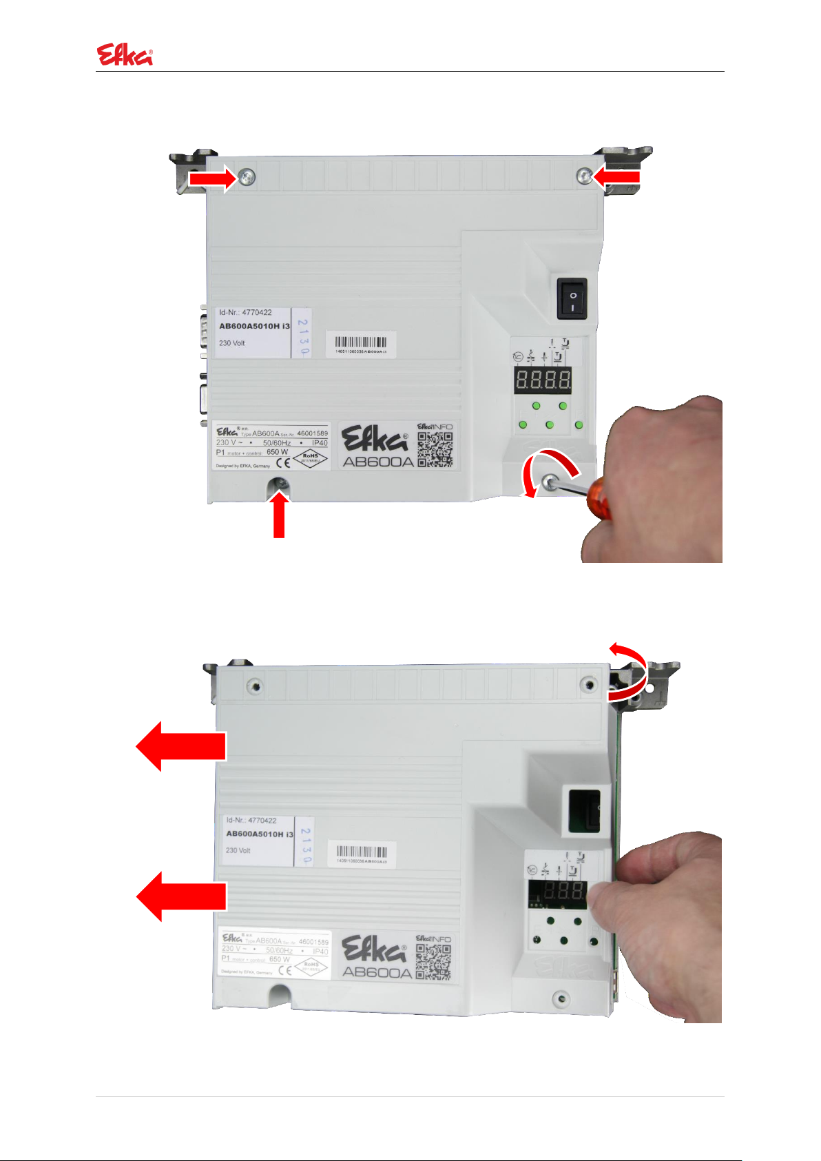
3.2 Removing the control housing
P a g e | 5
- AB600A /AB611A /AB620A
Remove the 4 screws of thefront housing (Torx T 20).
Remove front housing.
Note: First tip the cover slightly to the top, then push it away to the left.
6 | P a g e
- AB600A /AB611A /AB620A
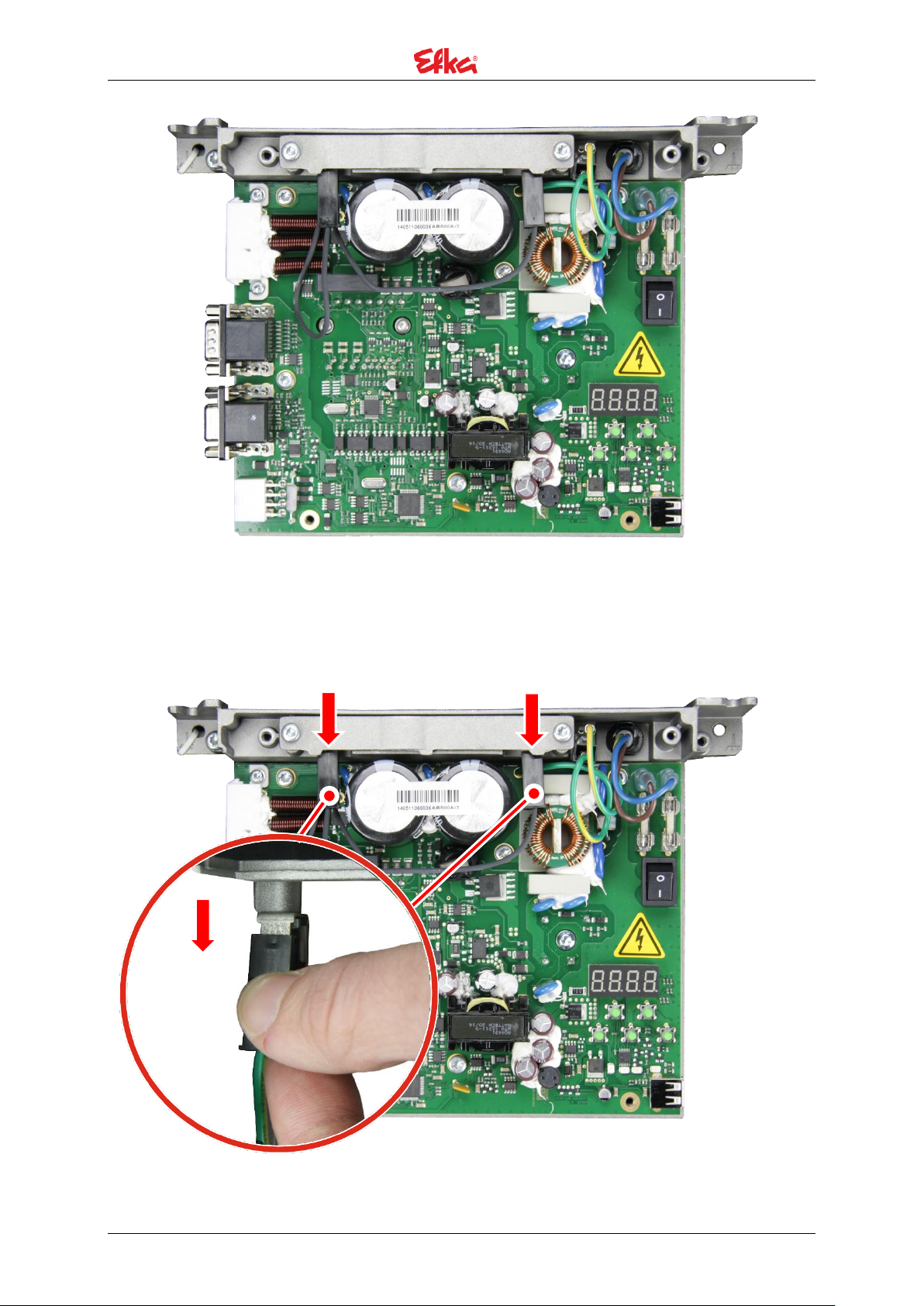
3.3 Removing the circuit board
Pull off the "Fast on" plug connector of the brake resistor.
P a g e | 7
- AB600A /AB611A /AB620A
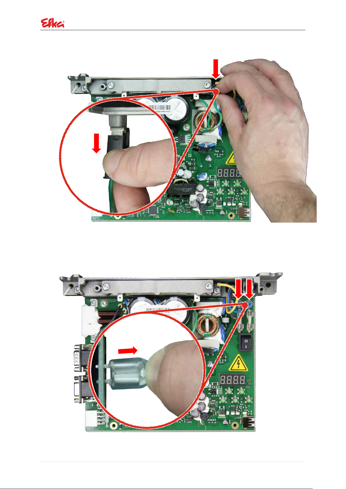
Pull off the "Fast on" plug connector of the board ground.
Press the lock of the "Fast on" plug with your fingernail and pull it carefully from the circuit
board.
8 | P a g e
- AB600A /AB611A /AB620A
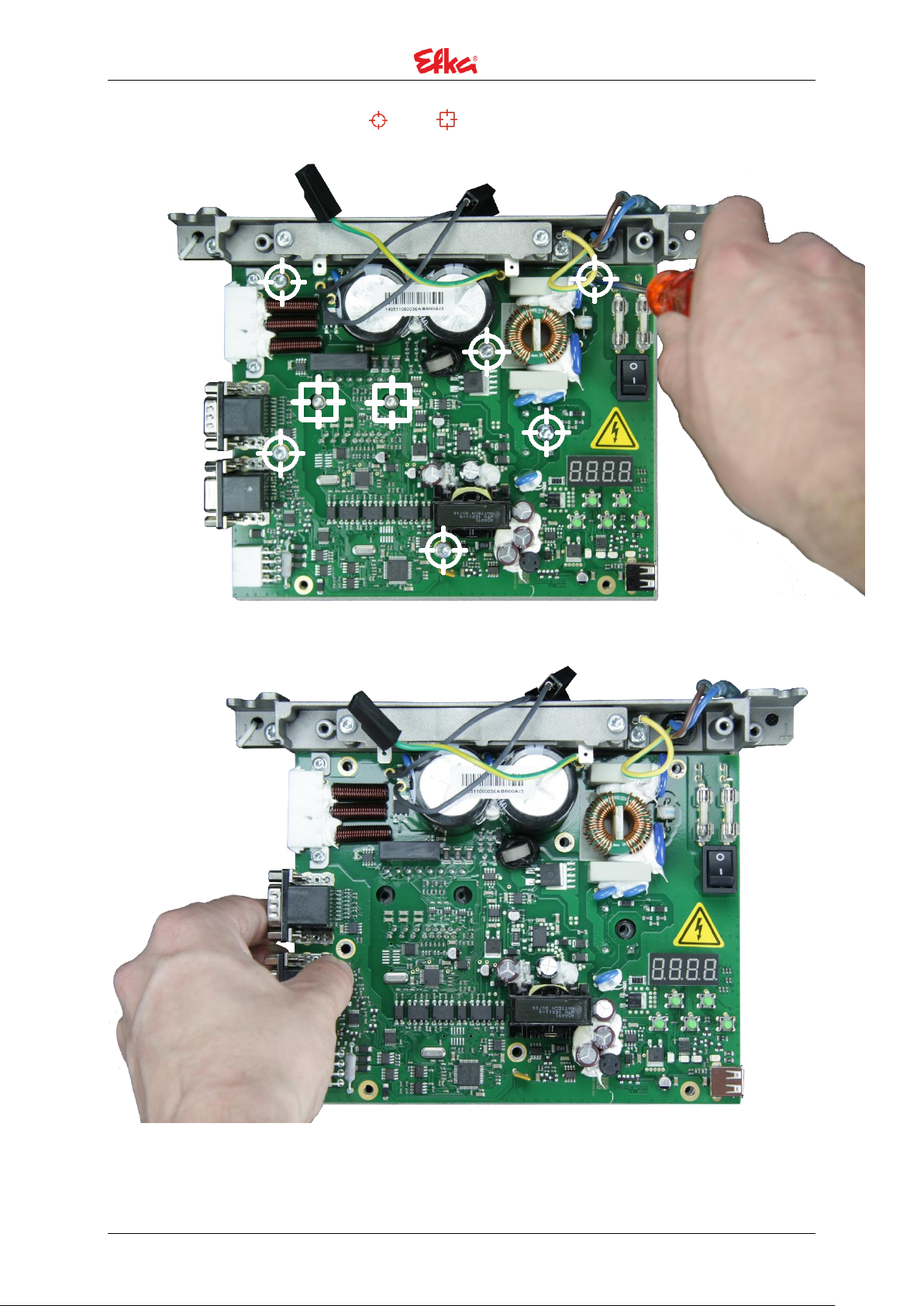
Remove the 8 marked screws (Torx T20 & T10)
Carefully lift the circuit board.
P a g e | 9
- AB600A /AB611A /AB620A
( -Nr. 1114051)
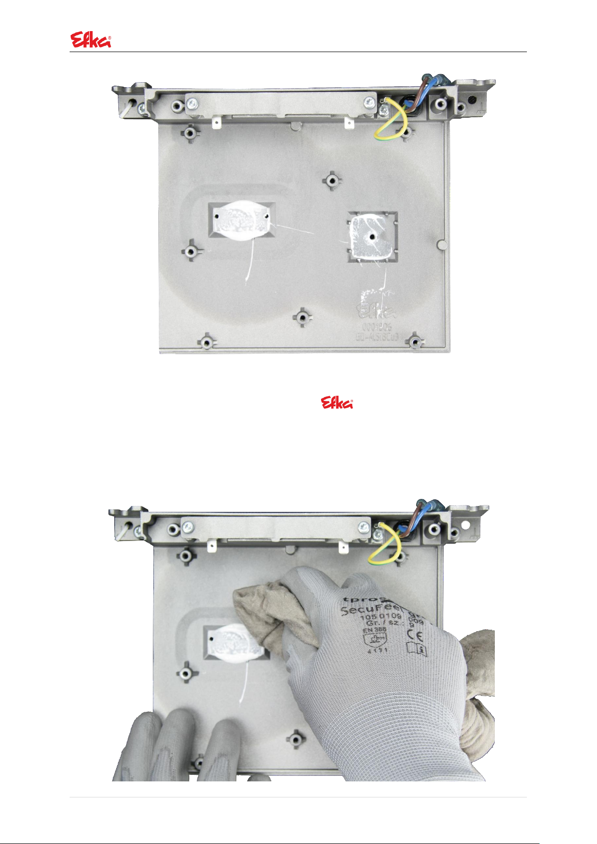
3.4 Installation oft he circuit board
Remove the residues of the thermal compound from the housing and ensure that the contact
surfaces are dust-free.
Note: Ware gloves to protect your skin!
10 | P a g e
- AB600A /AB611A /AB620A
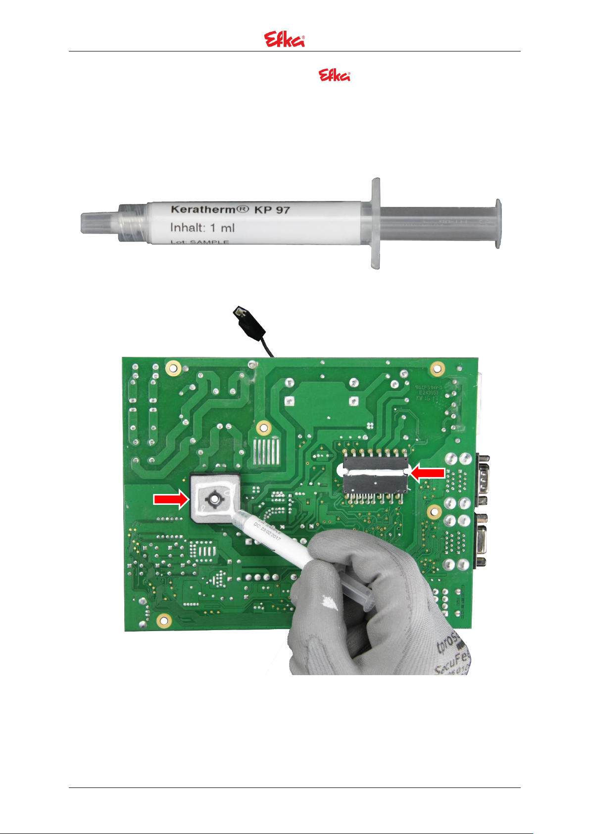
( -Nr. 150 5077)
Apply the thermal compound from repair set
on powermodul and rectifier on the cicruit board. Follow the illustration!
Note: Ware gloves to protect your skin!
Note: Apply the thermal compound ca. Ø 3mm thick!
P a g e | 11
- AB600A /AB611A /AB620A
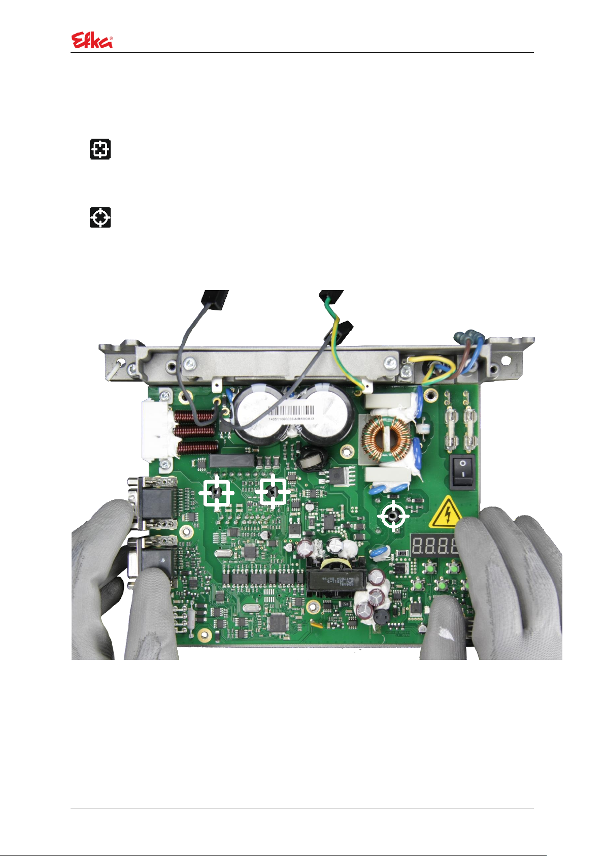
Carefully insert the board.
Insert the marked screws and tighten them with specified torque.
Note: make sure that the drillings are concentric over each other!
2x M3x16 (Torx T10) Torque: 0,8 +/-0,2 Nm
IMPORTANT! Fix the screws reciprocally! Fix the screws again after 10 minutes with 0,8 +/-0,2 Nm
torque!
1x M4x16 (Torx T20) Torque: 2 +/-0,2 Nm
IMPORTANT! Fix the screws again after 10 minutes with 2 +/-0,2 Nm torque!
12 | P a g e
 Loading...