

Page 1

Section
1
Section 13800 Information
1.1 General Description
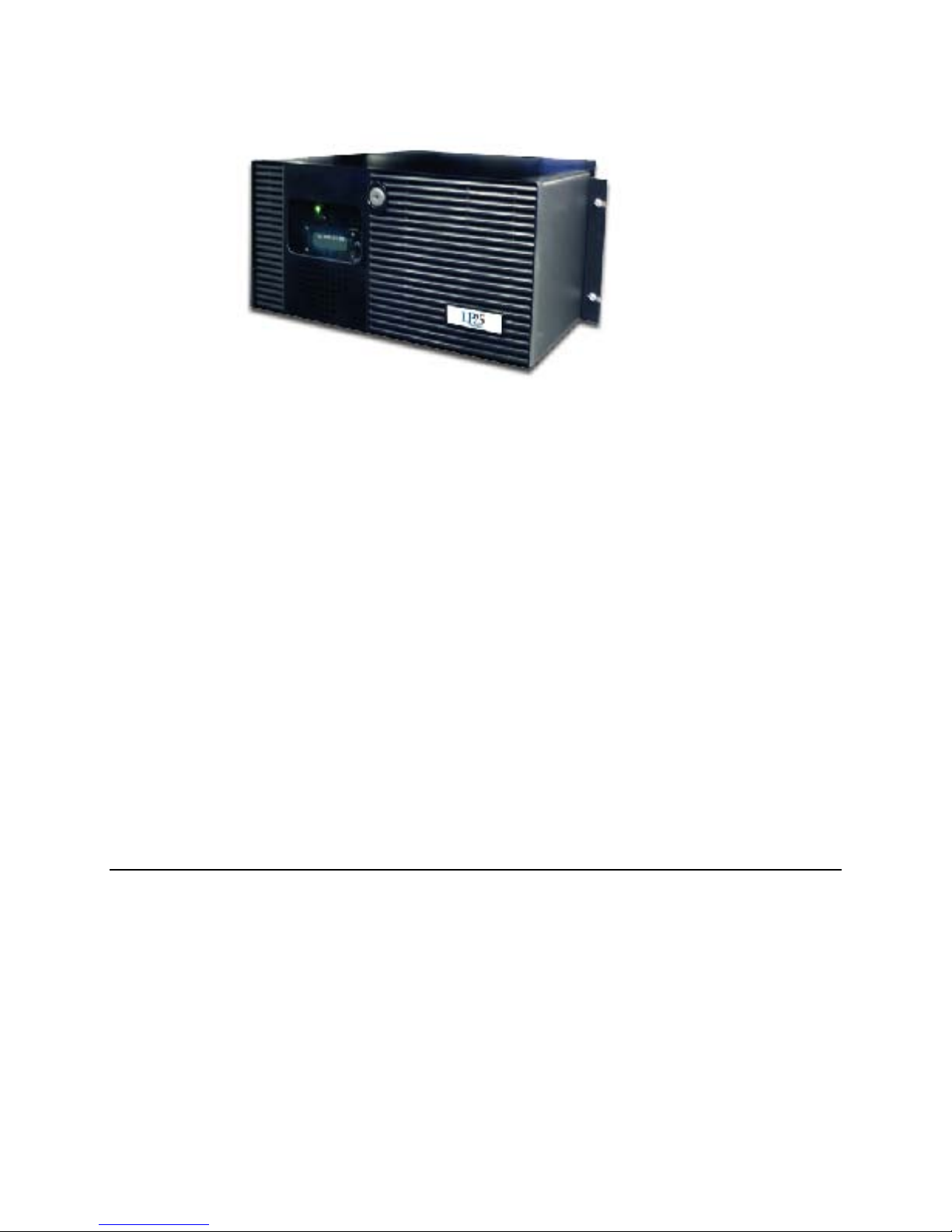
The EF Johnson Technologies 3800 Series Digital Repeaters are designed specifically for radio trunking
operations. The 3800 integrates the functions of radio repeater and trunking channel controller into one
unit. See Figure 1.1.
Figure 1.1 3800 Series Digital Repeater
October 2009 3800 Digital Repeater Operating Manual 1 -1
Page 2
3800 Information
The radio
component provides a transmitter and receiver with software programmable frequency and power
selection. Transmitter and receiver signals are encoded and sampled by dual Digital Signal Processors
DSP).
Channel controllers in each repeater manage the control and traffic channels for frequency assignments
and transmitter power level. The local site controller is integrated into one of the repeaters. The Trunked
IP25 System supports the ability to have backup site controllers, but only one site controller is required
per site.
Multiple repeaters may be used per site to accommodate multiple frequencies, traffic level, and provide
radio channel backup. One repeater is required for a control channel and one or more repeaters for traffic
channels.
A built-in ethernet interface lets the repeater communicate over the Trunked IP25 System IP network to
other system components.
1.1.1 Models & Features
The 3800 Series Repeater consists of various models and features. Please refer to the 3800 Digital
Repeater Service Manual for descriptions of the different models, identification and part number
information.
1 -2 3800 Digital Repeater Operating Manual October 2009
Page 3
3800 Information
1.2 Functional Description
The EF Johnson Technologies 3800 Series Digital Repeater is a trunked repeater with built-in trunking
control. The Trunked IP25 System Channel Controller function is integrated into the repeater subsystem.
The 3800 Repeater uses frequency synthesizer and Digital Signal Processor (DSP) technologies to
provide digital control of the radio channels. Software defined configurations allow for quick updates and
programmable operating frequency, output power, and other key functions.
Multiple repeaters may be used per site to accommodate multiple frequency bands and provide radio
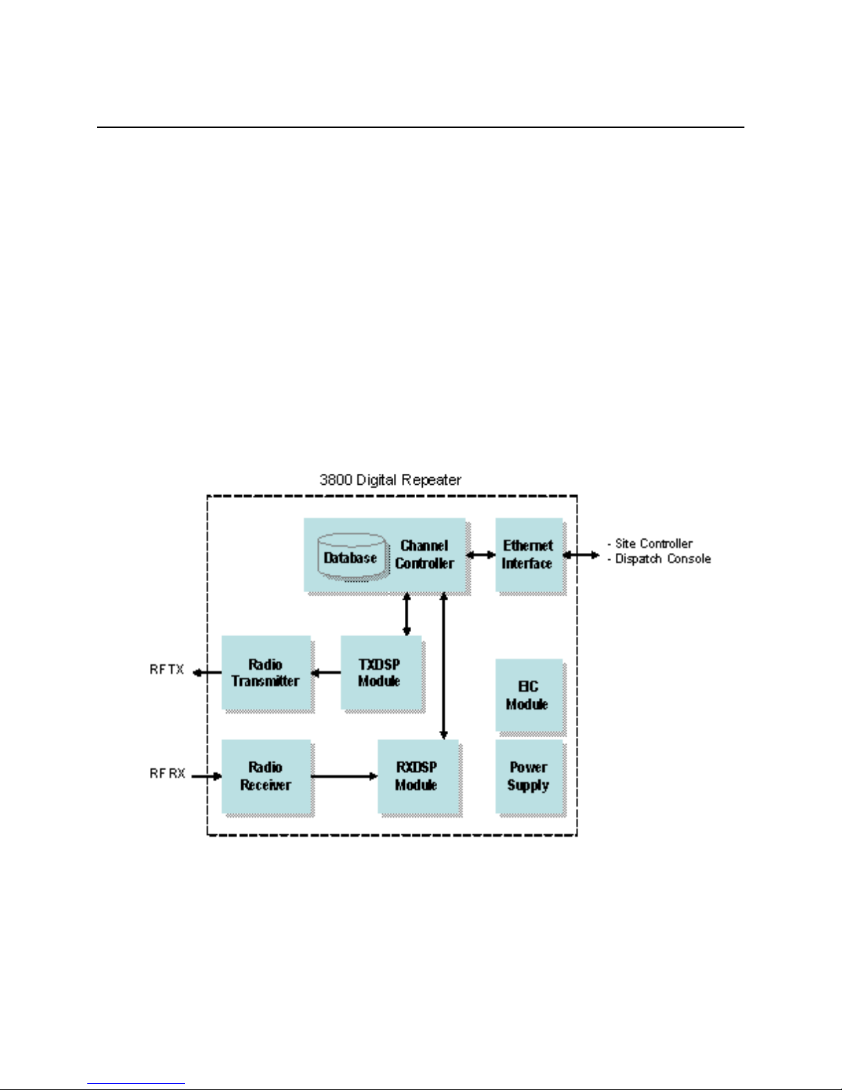
backup. The 3800 is comprised of the following functional modules
( Figure 1.2):
Figure 1.2 3800 Repeater Subsystem Functional Diagram
Channel Controller
All channels are managed by the integrated Channel Controller. The controller provides overall channel
control for control and traffic channels in a repeater. It manages the radio transmitter and receiver
frequency assignments and power lev els. Th e Chan nel Controller checks channel status and reports any
October 2009 3800 Digital Repeater Operating Manual 1 -3
Page 4

3800 Information
channel failures or processing errors to the Site Controller. One Channel Controller is used for each radio
repeater subsystem (in multiple repeater systems).
TXDSP Module
The TXDSP module manages the repeate r radio transmitter interface. This module prov ides chann el
encoding with forward error detection and correction coding. It receives data packets from the channel
controller and creates a signal for the transm itter.
Radio Transmitter
The Radio Transmitter is digital synthesizer based to ensure on-frequency and high stability operation. It
converts the processed signal from the TXDSP module into a radio frequency (RF) signal for
transmission.
Radio Receiver
The Radio Receiver is digital synthesizer based to ensure on-frequency and high stability operation. It
receives and converts the radio frequency signals for processing by the RXDSP module.
RXDSP Module
The RXDSP module manages the repeater radio receiver interface. It processes the received signal
samples from the radio receiver into data packets. The module then sends the data packets to the Channel
Controller.
Ethernet Inte rface
The repeater communicates over its Ethernet interface with the Site Controller, Dispatch Console, and
Network Management System (NMS).
EIC Module
The EIC module provides a user interface to the repeater including a 2-line display and push button rotary
knob for menu navigation.
1 -4 3800 Digital Repeater Operating Manual October 2009
Page 5

3800 Information
Power Supply
The power supply accepts the AC line power input and converts it into the various DC power
requirements of the repeater.
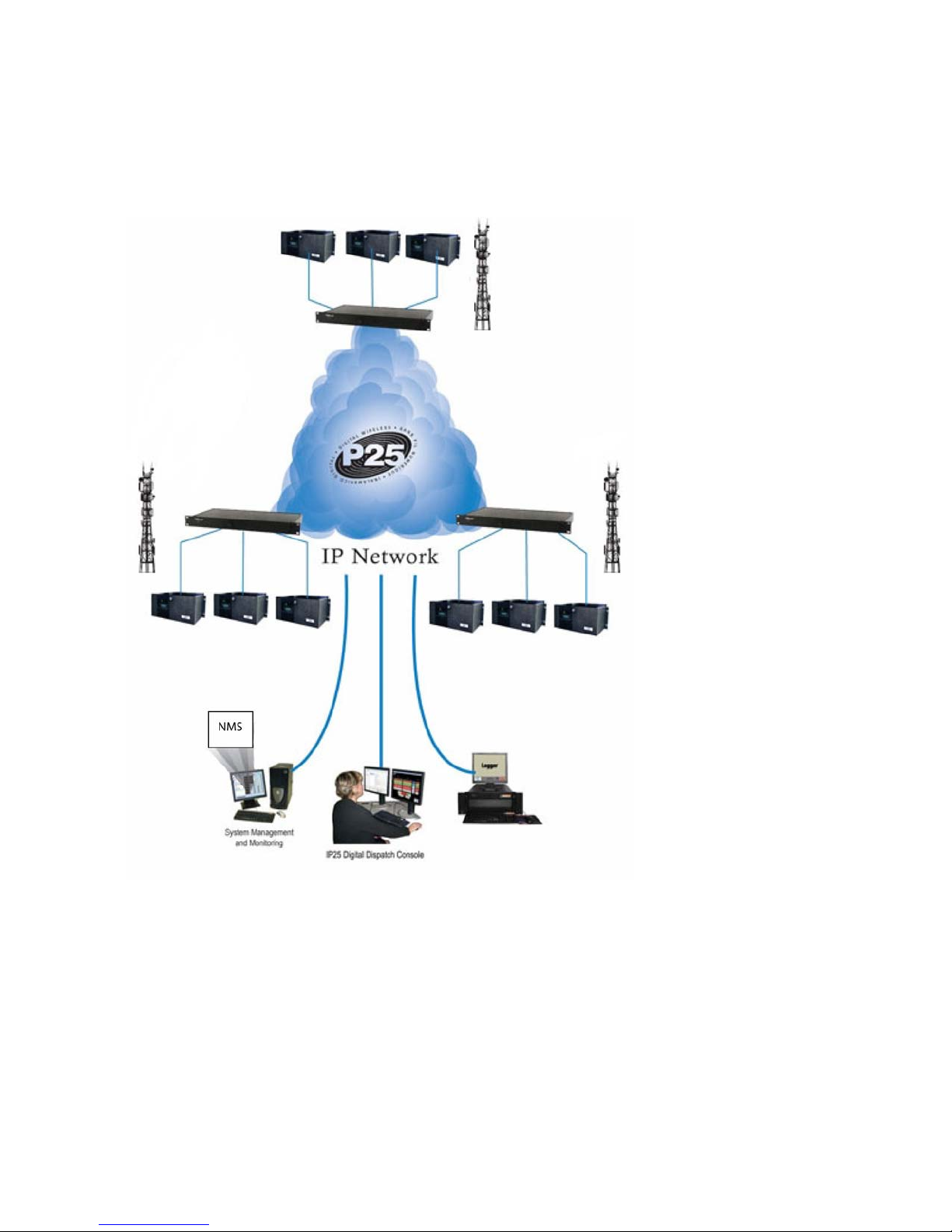
1.3 System Configuration
The 3800 Repeater is typically used as the repeater component in an EF Johnson Technologies Trunked
TM
IP25
IP network configuration lets a system administrator manage the radios and system components exactly as
if they were computers on a LAN. See Figure 1.3.
Configuration of 3800 repeaters is performed through the Network Management System (NMS). Refer to
Section 3.3, “Trunked System Operation”in this manual for system operating information.
System. This is an Internet Protocol (IP) Local Area Network (LAN) based radio system. Using a
October 2009 3800 Digital Repeater Operating Manual 1 -5
Page 6
3800 Information
Figure 1.3 Trunked IP25 System
1 -6 3800 Digital Repeater Operating Manual October 2009
Page 7

3800 Information
1.4 Safety Information
This repeater emits radio frequency (RF) energy when transmitting. Make sure to observe
all RF energy exposure standards when installing, testing, repairing, and operating this radio equipment.
The FCC has adopted a safety standard for human exposure to RF energy. Proper operation of this
repeater under normal conditions results in user exposure to RF energy below the Occupational Safety
and Health Act and Federal Communication Commission limits.
- Do not allow the antenna to touch or come in very close proximity with the eyes, face, or any
exposed body parts while the repeater is transmitting.
- To comply with FCC RF exposure limits, do not operate the transmitter of a stationary radio (base
station or marine radio) when a person is within fourteen (14) feet [four (4) meters] of the antenna.
- Do not operate the repeater in explosive or flamm ab le atm ospheres . The tran sm itte d repeater energ y
could trigger blasting caps or cause an explosion.
- Do not operate the repeater without the proper antenna installed.
- Do not allow children to operate transmitter equipped repeater equipment.
Note The above warning list is not intended to include all hazards that may be encountered
when using this repeater.
This device complies with Part 15 of the FCC rules. Operation is subject to the condition that this device
does not cause harmful interference. In addition, changes or modification to this equipment not expressly
approved by EF Johnson Technologies could void the user’s authority to operate this equipment (FCC
rules, 47CFR Part 15.19).
The information in this document is subject to change without notice. EF Johnson Technologies will not
be liable for any misunderstanding due to misinformation or errors found in this document.
1.5 More Information
Additional information is available for the 3800 Digital Repeater. Contact your supervisor, site radio
administrator or EF Johnson Technologies representative should you need one of these additional
manuals. Refer to the following:
- EF Johnson Technologies 3800 Digital Repeater Installation Manual
October 2009 3800 Digital Repeater Operating Manual 1 -7
Page 8

3800 Information
- EF Johnson Technologies 3800 Digital Repeater Service Manual
- EFJohnson Trunked IP25 System Installation & Configuration Manual
- EFJohnson Trunked IP25 System Administration & Maintenance Manual
1 -8 3800 Digital Repeater Operating Manual October 2009
Page 9
Section
2
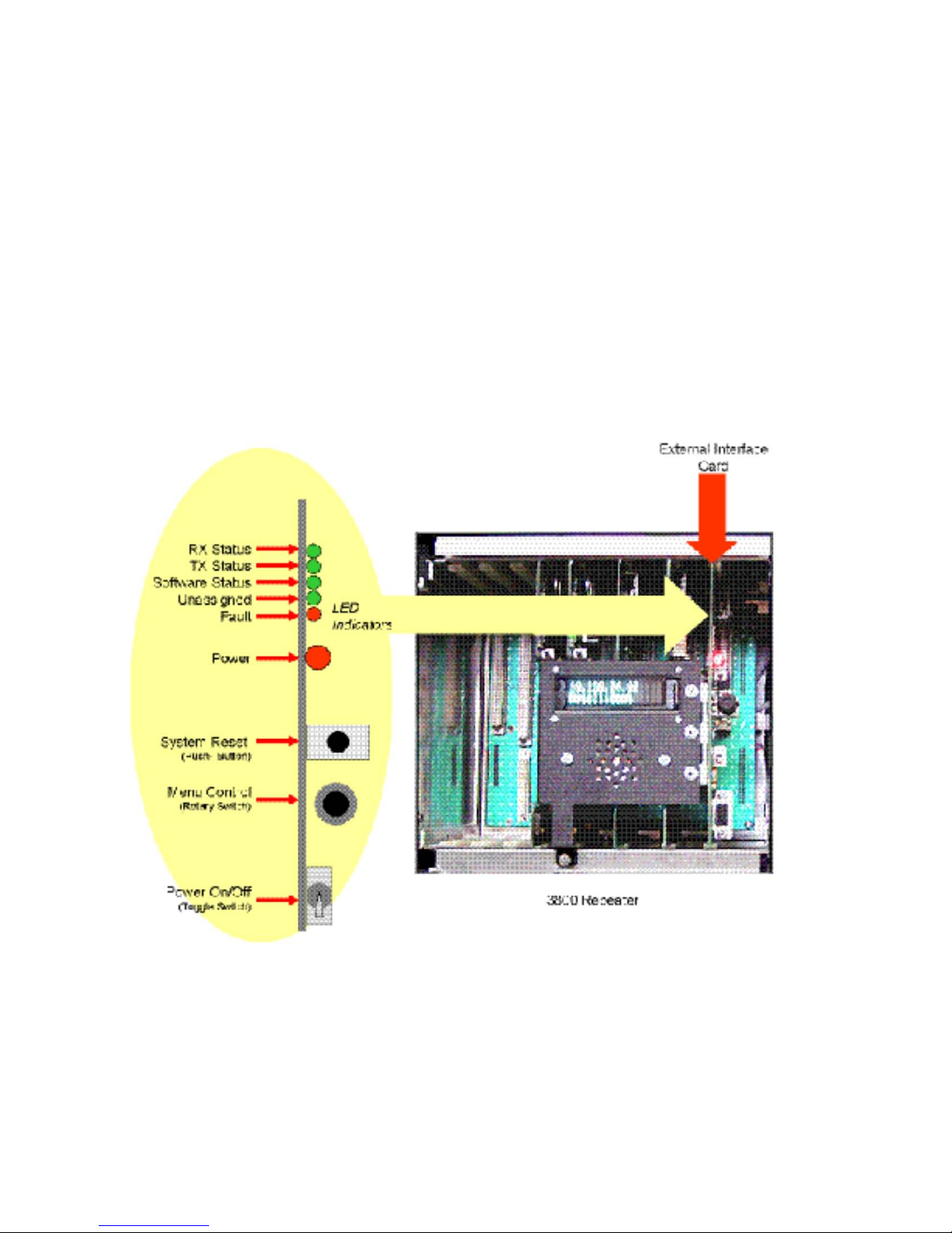
Section 2Controls & Indicators
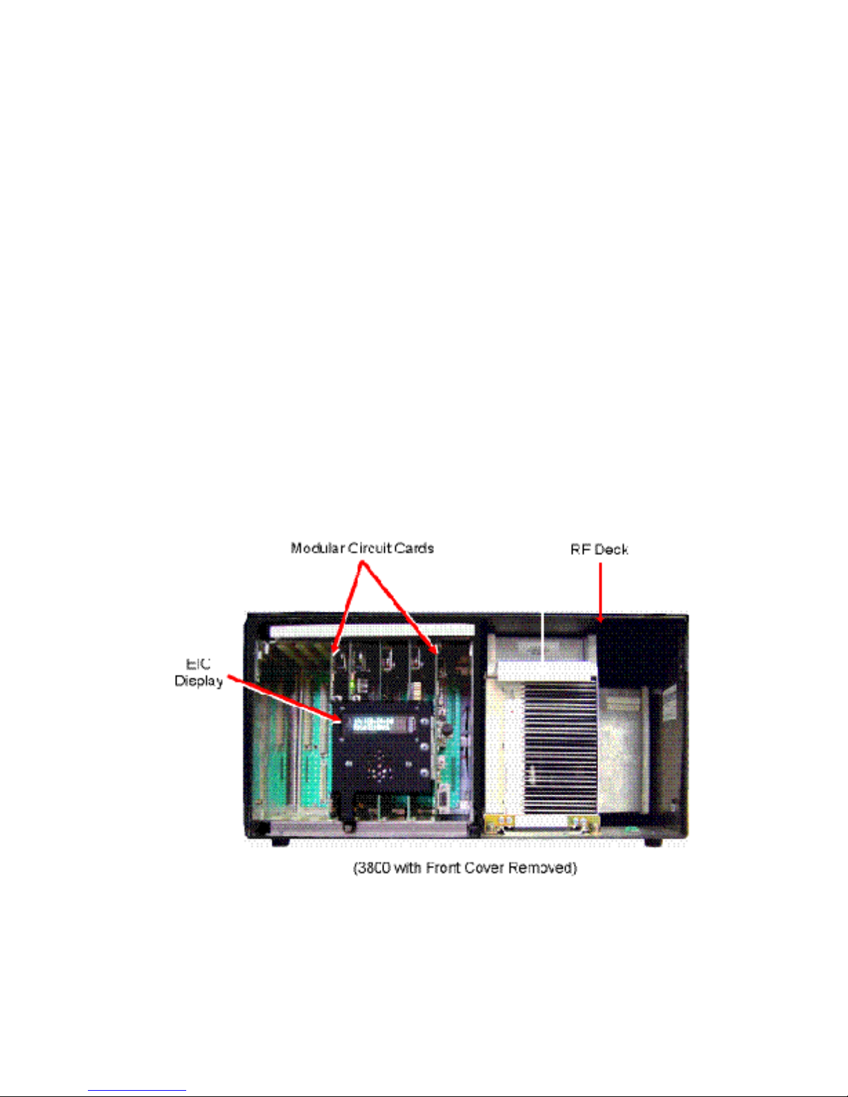
Most controls and indicators on the 3800 are located behind the front panel. Figure 2.1 shows the 3800 with its front
panel removed. 3800 controls and indicators are located on the Site Controller card, Channel Controller card, and the
External Interface card. These are described and illustrated in greater detail in the following sections.
Figure 2.1 3800 Repeater with Front Panel Removed
October 2009 3800 Digital Repeater Operating Manual 2 -1
Page 10
Controls & Indicators
Site Controller Controls and Indicators
Auxiliary Status LED
LED Indication
Software Version < 3.0
Software Version > or = 3.0
On Solid
Ethernet link datarate = 100 Mbps
Site controller is in standby as redundant
Flashing
NA
Site Controller is active in Trunking
Off
Ethernet link datarate = 10 Mbps
NA
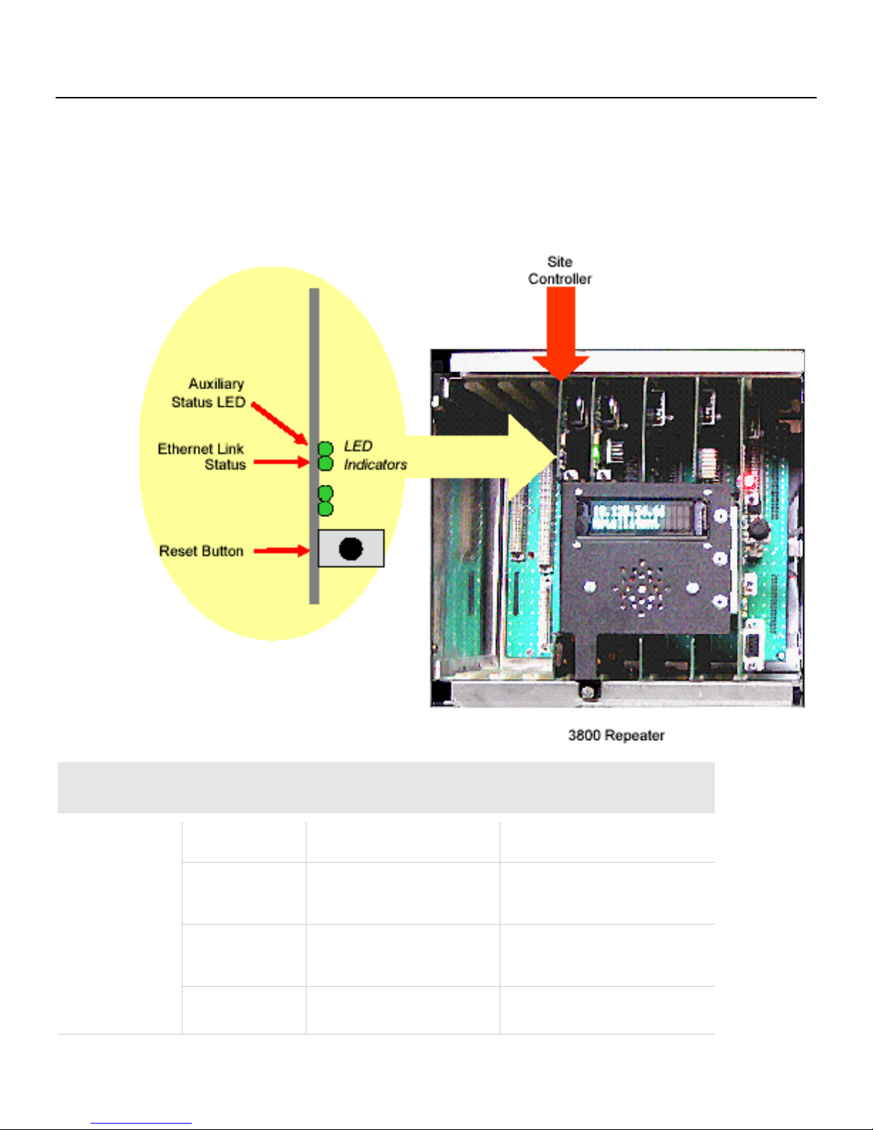
2.1 Site Controller Card
The site controller card provides the high-level call processing for the entire site. Unless using backup site controllers,
only one repeater in each system contains a site controller card. The Site Controller card’s controls and indicators are
illustrated in Figure 2.2 and described following.
Figure 2.2 Site Controller Controls and
Indicators
2 -2 3800 Digital Repeater Operating Manual October 2009
controller.
Mode.
Page 11
Controls & Indicators
Ethernet Link Status
This indicates the main Ethernet link data rate. If this LED is on, the rate is 100 Mbps. If this LED is off,
Reset Switch
Pressing this switch resets the controller card.
the rate is 10 Mbps.
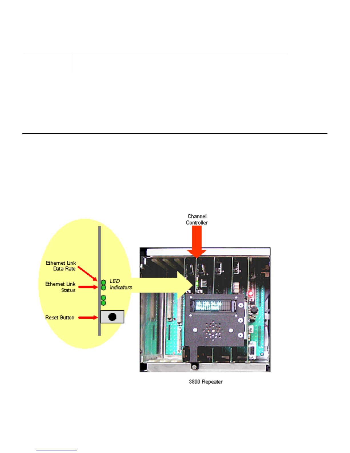
2.2 Channel Controller Card
The channel controller card controls either a single t raf fic chann el or a single control channel for a particular 3800
repeater system. The Channel Controller card’s controls and indicators are illustrated in Figure 2.3 and described
following.
Figure 2.3 Channel Controller Card Controls and Indicators
October 2009 3800 Digital Repeater Operating Manual 2 -3
Page 12

Controls & Indicators
Channel Controller Controls and Indicators
Ethernet Link Data Rate LED
This indicates the main Ethernet link data rate. If this LED is on, the rate
Ethernet Status LED
If on, the repeater is connected to Ethernet.
Reset Switch
Pressing this switch resets the channel controller card.
is 100 Mbps. If this LED is off, the rate is 10 Mbps.
Note Both of the Channel Controller card LEDs should be ON continuously after you initialize the repeater.
(Two LEDs are not used in the field.)
2 -4 3800 Digital Repeater Operating Manual October 2009
Page 13

Controls & Indicators
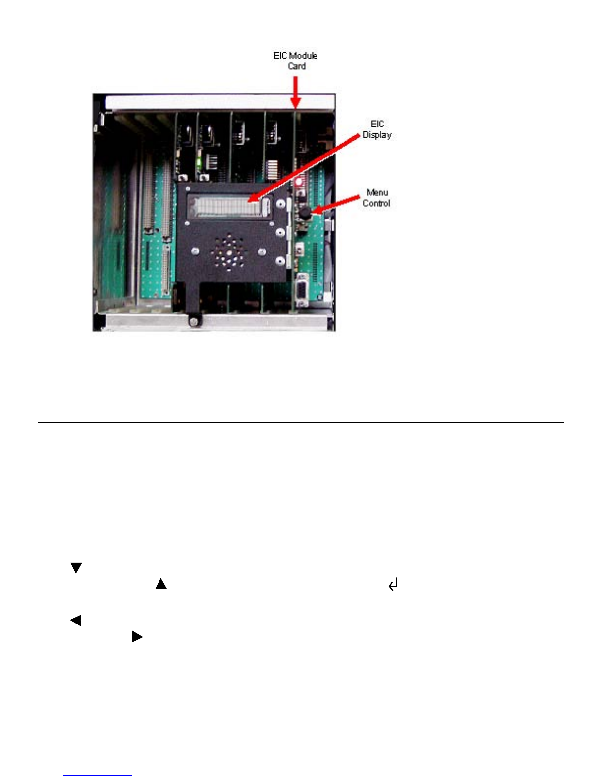
2.3 External Interface Card (EIC)
The External Interface Card (EIC) contains most of the switches and LEDs that you use to monitor and control the
repeater. The EIC controls only the channel controller card. These contro ls an d indicators are il lu s tra te d in Figure 2.4
and described as follows.
Note LED indications discussed here apply only during normal operation (i.e., not during diagnostics)
EIC Controls and Indicators
October 2009 3800 Digital Repeater Operating Manual 2 -5
Page 14

Controls & Indicators
EIC Controls and Indicators
RX DSP Data LED
When ON, receiving decodable data.
RX synthesizer is locked, receiving decodable user
TX DSP Data LED
When ON, transmitter is active.
System Status LED
When ON, system is operating properly.
Channel Status LED
When ON, repeater is operationally active and in service.
Alarm LED
When ON, a Critical alarm is pending.
RF Interference (RFI)
Flashing Green
RFI Detection Disabled
Solid Green
RFI Detection Enabled: no RFI detected
Solid Orange
RFI Detection Enabled: Alarm level RFI
Solid Red
Flashing Red
RFI Detection not supported
• Control channel –
registrations, affiliations or call requests
• Traffic channel – RX synthesizer is locked, receiving user voice
traffic. This LED flickers as users key and dekey, enter and exit
fades, etc.
• Control channel – TX synthesizer is locked, PA is keyed up, no RF
deck alarms. This LED is on continuously unless there is a failure
condition
• Traffic channel – TX synthesizer is locked, PA is keyed up with user
voice, no RF deck alarms. This LED is on for the duration of a voice
call. During fail-soft operation, this LED is on continuously.
Status
This LED indicates that all tasks are reporting in to the watch dog timer.
As long as all tasks are reporting in, this LED is on. If a failure occurs,
the LED is off.
This LED is on while a repeater is administratively and operationally
active. If configuration is corrupted resulting in the repeater being
unusable, the LED is off.
This indicates that service is required. An example would be an RF
transmitter failure.
detected
RFI Detection Enabled: Disable level RFI
detected
2 -6 3800 Digital Repeater Operating Manual October 2009
Page 15

System Reset Switch
This is the reset switch for both the channel controller and the site
controller (if one is installed). Pressing this switch resets the control
Menu Control Switch
Pressing or rotating this control enables the menu mode. When the
Power On/Off Switch
Turns repeater power on and off. It connects to the power supply remote
Channel Controller Port
RS232-C jack that connects to channel controller processor.
Display
This 2 line x 16 character vacuum fluorescent display can indicate the
up, it indicates the various sequences that are executed by
logic and restarts the operating program(s) from the beginning.
menu mode is selected, pressing and rotating this control scrolls
through and selects the various menus and parameters.
enable line and switches the main power supply power sources.
following information:
• On powerthe control logic as the operating program starts.
• During normal operation, the display indicates
• The repeater name
• Whether the repeater’s channel is a voice channel (V) or a control
channel (C)
• The repeater’s IP address
Controls & Indicators
October 2009 3800 Digital Repeater Operating Manual 2 -7
Page 16

Section
3
Section 3Operation
3.1 Operational Interface
The External Interface Card (EIC) module provides the primary manual interface to setup and operate the 3800
Repeater. Using the two-line display, the EIC provides a menu structure of functions and settings for operating the
repeater. (See Figure 3.1.)
Figure 3.1 3800 EIC Interface
October 2009 3800 Digital Repeater Operating Manual 3 -1
Page 17
Operation
3.2 EIC Menu Modes
The main menu mode can be selected to display various repeater parameters. Figure 3.2 is a block diagram of the menu
mode struct
The menu mode is selected and controlled by the Menu Control knob as follows.
• To select the menu mode, press or rotate the Menu Control knob. The first main menu “CPU” is then displayed.
• In general, rotating the Menu Control scrolls through available parameters, and pressing it selects the displayed
parameter.
• The
selected. Conversely, if
parameter or function is selected.
ure.
icon in the upper right corner of the display indicates that if the knob is pressed, the next lower menu level is
is displayed, the next higher level is selected. The icon indicates that the displayed
• The
left. Likewise, the
• Selecting [Back] returns a level up in menu hierarchy.
3 -2 3800 Digital Repeater Operating Manual October 2009
icon in the left-most position of the bottom line indicates that additional parameters have scrolled off to the
icon in the right-most position indicates additional parameters have scrolled off to the right.
Page 18
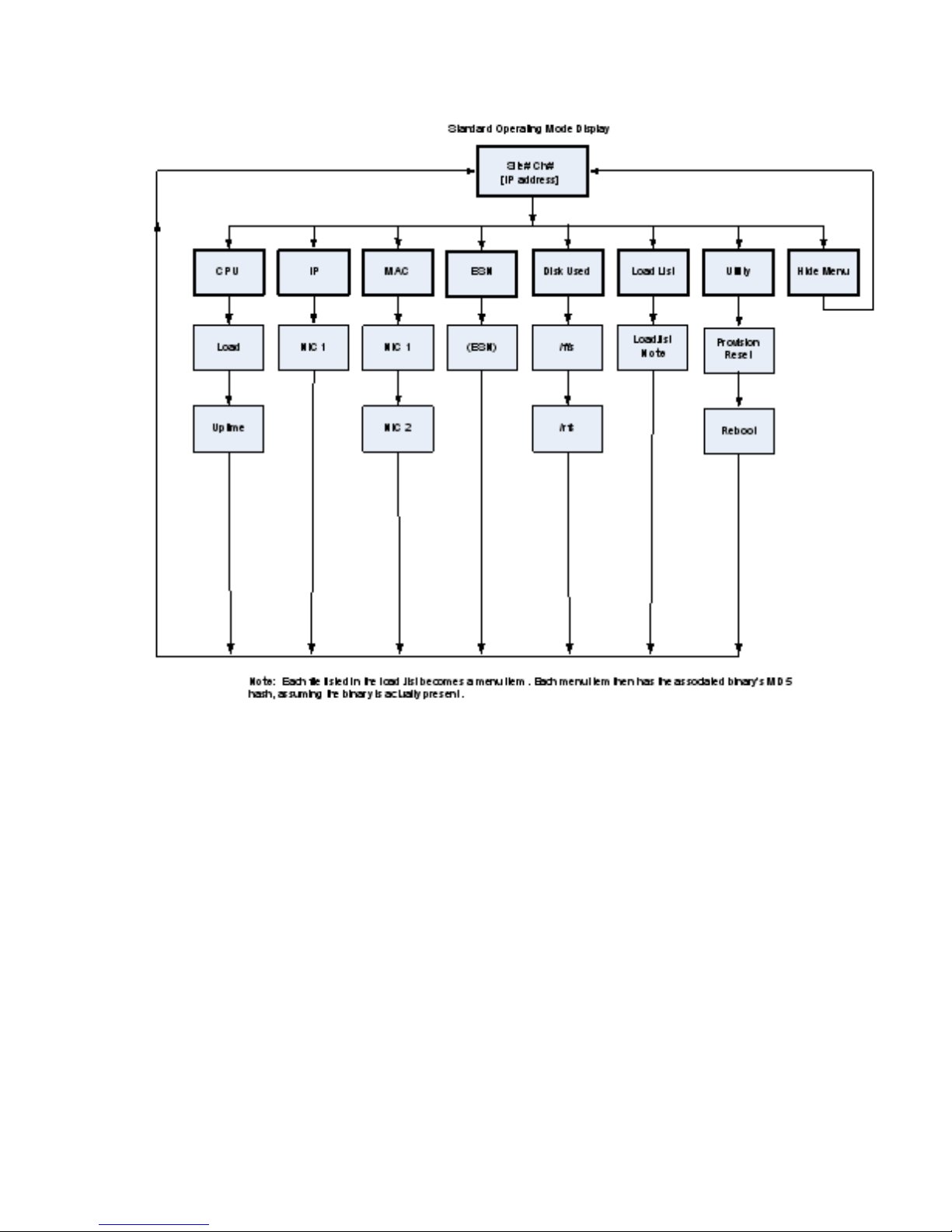
Figure 3.2 Main Menu Mode Block
Diagram
Operation
Note The repeater also has a diagnostic menu mode. Refer to Section 4 of this manual for a description of
this mode.
October 2009 3800 Digital Repeater Operating Manual 3 -3
Page 19

Operation
3.2.1 CPU Menu
This menu displays CPU information.
- Load - Current system load.
- Uptime - Length of time in seconds that the CPU has been running.
3.2.2 IP Menu
This menu displays the Internet protocol (IP) address associated with the repeater.
- NIC1 - The first network interface card. Some repeaters may have more than one network interface card.
3.2.3 MAC
This menu displays the MAC information for the repea ter.
- NIC1- - The first network interface card. Some repeaters may have more than one network interface card.
- The second network interface card.
NIC2
3.2.4 ESN
This menu displays Electronic Serial Number (ESN) information for the repeater.
- (ESN)
- Electronic Serial Number for the repeater.
3.2.5 Disk Used Menu
This menu shows the amount of used disk space (disks) for each item in the menus below this menu.
- /ffs - Shows disks used for /ffs (Flash file system).
- /rfs - Shows disks used for /rfs (RAM file system).
3 -4 3800 Digital Repeater Operating Manual October 2009
Page 20

Operation
3.2.6 Load List Menu
This menu displays the list of items in current load list.
- load.lst - Shows the last digits of the MD5 hash for the /ffs/etc/load.lst file. Each line in this file becomes a menu
item. Each menu item then has the associated binary’s MD5 hash, assuming the binary is actually present.
Note Shows the cumulative MD5 hash for all binaries listed in the load.list.
3.2.7 Utility Menu
This menu provides access to various utility functions for the system.
- Provision Reset - Replaces manifest files currently installed on the board
(/ffs/etc/site.maf and /ffs/etc/site.maf.md5) with updated files from the NMS.
- Reboot - Reboots the channel controller without regard for the current state.
Tip To reboot the channel controller, it is preferable to use this command rather than to press the Reset switch.
Note
When you reboot the channel controller, the reboot may not happen immediately. The reboot may require several
seconds.
3.2.8 Hide Menu
This menu exits the menu mode.
3.3 Trunked System Operat io n
When used in a Trunked IP25 System infrastructure, the 3800 repeater communicates all control and status to the
Network Management System (NMS). All system control setup is through the NMS.
Refer to the EFJohnson Trunked IP25 System Administration & Maintenance manual for additional information on
3800 Repeater operation in a system infrastructure.
October 2009 3800 Digital Repeater Operating Manual 3 -5
Page 21

Section1
3800 Repeater Troubleshooting (Continued)
Problem
Test Action / Procedure / Solution
If any action corrects the problem, return to normal equipment operation. If an action does
Troubleshooting & Diagnostics
The 3800 repeater includes a diagnostic and troubleshooting mode. Running diagnostics is an alternate
startup operational mode and is not available while the system is already running. During boot up, the
normal boot up sequence can be aborted and an alternate boot personality may be selected. One alternate
boot personality is the Diagnostic Personality.
.1 Repeater Troubleshooting
You can troubleshoot the 3800 repeater to the circuit board or module replacement level. If you
experience problems with the 3800, first perform the following basic checks. If these checks do not
correct the problem, continue with the troubleshooting chart procedures that apply to your problem.
• Perform a visual inspection:
- Remove each card and check for bent pins.
- Replace each card and be sure that all cards are properly seated into the card chassis.
- Make sure the RF deck is securely seated into the chassis.
- Confirm that the repeater’s power supply is receiving enough AC power.
- Confirm there is a properly-tuned antenna connected to the Transmit and Receive RF ports.
- Confirm that environmental temperature is within specified limits.
- Confirm that the repeater’s location is properly ventilated.
- Confirm that network cables are connected securely, and network equipment is on.
Repeater Troubleshooting Chart
not correct the problem, then proceed to the next test action.
Page 22

Repeater does not power up
Repeater indicates powered on, but
• Reset the repeater by momentarily pressing the System Reset pushbutton on the EIC
Fault or multiple faults indicated
• If the repeater indicates it is powered on, it may be possible to reboot the repeater
Repeater not transmitting
• Verify the repeater has supplied AC power.
• Verify the repeater has supplied AC power
• Check that the Power On/Off toggle switch on the EIC card module is set to the On
position. When set to On, the EIC Power LED should be blinking. If not, replace the
power supply module.
does not operate
card module.
• Perform a Power Supply Diagnostic:
1 From the diagnostics application, select
Power Supply > PS Test > PS output > Start
Confirm that the power supply output is approximately 25.0 volts
1
Stop the test.
1
If the power supply test fails, then replace the power supply.
1
1
If the red EIC Alarm LED remains on, select the
Faults menu item to view
detected faults.
1
If the PS Temp- The power supply temperature has exceeded limits fa ult is
detected, replace the power supply assembly.
into the diagnostics mode to review any detected faults.
1 Activate the diagnostics application, and select the
2
Review the indicated fault conditions and take the appropriate action.
Faults menu item.
• If multiple faults occur, it is possible that the measurements themselves are at fault.
Replace the Channel Controller card. If problem persists, replace the RF deck.
• Ensure that the TX DSP card is fully seated, with no bent pins.
• Ensure that the Channel Controller card is fully seated, with no bent pins.
• Reboot the Channel Controller card by momentarily pressing the Reset button on the
card. If this does not correct the problem, continue to the Transmitter Test.
• Perform a Transmitter Test - Connect a test receiver to the RF transmit port. Make
sure that sufficient attenuation is provided to protect the test receiver.
1 From the diagnostics application, select
2
Verify that the Tx Frequency is within specified limits.
2
Verify that the Tx Power output is within specified limits.
2
Verify that the Tx Modulation level is within specified limits.
2
Verify that the test receiver can decode the P25 1011 Hz tone.
2
Stop the test.
2
If any of the TX tests fail, then replace the RF deck.
2
If the red EIC Alarm LED remains on, select the
detected faults.
TX > TX Test > Cont > Start
Faults menu item to view
Page 23

2
If any of the following TX faults are detected, replace the RF deck.
Repeater not receiving
• Verify the repeater has supplied AC power.
Repeater not communicating over
• Verify the repeater has supplied AC power
- TX Synth Lock –T ransmit synthesizer out of lock.
- TX Temperature –PA temperature has exceeded limits.
- TX Fwd Power –Forward power is below limits when keyed.
- TX NoFwdPower –Forward power is above limits when not keyed.
- TX Power1 –Output of exciter is below limits.
- TX Power2 –Output of exciter is below limits.
- TX Power3 –Output of exciter is below limits.
- TX Power4 –Output of exciter is below limits.
- TX Imbal ½ Ratio of Tx Power 1 to Tx Power 2 is beyond limits.
- TX Imbal ¾ Ratio of Tx Power 3 to Tx Power 4 is beyond limits.
- TX Fan Op –Fan does not work.
- TX Fan1 Cur –Fan current is beyond limits.
- TX Fan2 Cur –Fan current is beyond limits.
2 A TX VSWR –The VSWR is beyond limits fault indicates an antenna problem.
Check all antenna connections at the antenna, feed line, and at the repeater. If
necessary, replace the antenna, and/or the feed line.
• Ensure that the RX DSP card is fully seated, with no bent pins.
• Ensure that the Channel Controller card is fully seated, with no bent pins.
• Reboot the Channel Controller card by momentarily pressing the Reset button on the
card. If this does not correct the problem, continue to the next item.
• Verify that the proper options are installed in case of P25 or VoIP
• Check the receive and transmit frequencies
• Make sure the RF deck is tightly secured.
• Verify NAC
• Check the LO and RF cable connection on the receive board
• Perform a Receiver Test - Connect an RF test signal to the RF receive port. This
signal should be set to the repeater’s receive frequency and modulated with a standard
P25 1011Hz Tone.
1 From the diagnostics application, select
Verify that receive sensitivity is within specified limits.
2
Stop the test.
2
If the BER test fails, then replace the RF deck.
2
If the display indicates “NO RSP”, then replace the receive DSP card.
2
2
If the red EIC LED remains on, select the
RX > RX Test > BER > Start
Faults menu item to view detected
faults.
2
If the RX Synth Lock - Receiver synthesizer is out of lock fault is detected,
replace the RF deck.
Page 24

LAN
• Make sure that the site LAN is operating
• Check the LAN connections to the repeater
SIte Controller not communicating
• Verify the repeater has supplied AC power
• Reboot the Channel Controller card and observe the LED indicators on this card. The
green LEDs should remain on, indicating that a network connection is present. If not,
replace the Channel Controller card.
over LAN
• Make sure that the site LAN is operating
• Check the LAN connections to the repeater
• If this repeater has an installed Site Controller card, reboot the Site Controller card
and observe the LED indicators on this card. The green LEDs should remain on,
indicating that a network connection is present. If not, replace the Site Controller card.
Activating Diagnostics
During repeater boot up, the option of aborting the boot process is indicated as it counts down on the EIC
display. Press and release the rotary knob during the countdown to abort the bootup process and activate
diagnostics. Once the boot up process is aborted, the Personality Menu is activated. Navigation through
the list of available personalities is performed by rotating the input control. If there exists only a single
personality, rotating the knob will appear to have no effect. Once the desired personality is displayed on
the front panel, pressing the input control knob will activate the currently selected personality.
.1.1 Navigation
Navigation is performed using the input control knob. All menu navigation is performed by both rotating
the front panel control knob and by depressing and releasing it. The act of depressing and releasing the
control knob is known as selecting. Rotating the knob clockwise is known as advancing or moving
forward, while rotating the knob counter clockwise is known as moving backward.
.1.1 LEDs
The LEDs on the EIC card indicate the following: (LEDs are numbered 1-5 from top to bottom.)
Note LED indications described here (see ) apply only during diagnostics mode (i.e., not
during normal operation).
Page 25
2) Rx LED -when illuminated, indicates receive activity. Only applicable during RX Tests.
3) Tx LED -when illuminated, indicates the transmitter is in a keyed state.
4) Software Operational LED -when illuminated, indicates the software is operating properly.
5) Unassigned LED -This LED does not have a functional indication.
6) Fault LED -when illuminated, a fault has been detected. See Monitors/Faults.
EIC Controls and Indicators: Diagnostic Mode Indications
Page 26

.0.1 Monitors/Faults
Diagnostic Menu Tree (Continued)
be applied.
--
[BACK]
A monitor is a comparison of a sensor measurement to a predetermined limit or range. Monitoring of
sensors is an ongoing process while running the diagnostics application. When a sensor measurement is
out of range, a fault is generated. Detected faults result in the illumination of the red LED, and a
corresponding message, which is viewable under the Faults menu.
Monitor tests are selectable via the menu items TX Monitors, RX Monitors, or PSMonitors. When
selected, a measured value used by the sensor comparison, and a Pass (“P”) or Fail (“F”) indication will
be displayed. The P/F indicates the results of the comparison to the valid range limits. If a monitor is not
enabled, an “NA” will be displayed.
Monitors are enabled automatically according to the state of the transceiver. (i.e. some TX Monitors are
enabled only when the transmitter is in the keyed state.) Even though monitors are always active when
enabled, only one can be displayed at a time. Before starting the display of a monitor, a previously
displayed monitor must first be stopped by selecting it a second time. The Fault LED is cleared on reboot.
Diagnostic Mode Menu Tree
The following lists the EIC menu tree available in diagnostic mode.
--> TX -Transmitter menu
>> TX Tests -Test the transmitter. Use the Tx Config menu to configure the
transmitter test.
-- Cont [START/STOP] -Start or stop a continuous transmitter test
-- Timed [START/STOP] -Start or stop a timed transmitter test
-- Cycle [START/STOP] -Start or stop a cycled transmitter test
--
[TOP]
--
[BACK]
>> TX Control -Control the transmitter now.
-- Turn PA [ON/OFF]-Toggle transmitter state. The transmitter will be
keyed at the currently configured frequency and power. No modulation will
-- Turn Fan [ON/OFF]-Toggle fan state. Note that this control is an “or”
control with the hardware circuitry. i.e. The fan cannot be turned off by this
control if the current PA temperature exceeds the default fan-on set point.
[TOP]
--
Page 27

>> TX Config -Configure the Tx Test. Note that configuration changes will not
TX Max PA Watt -Display maximum allowed power.
Low Dev Amp Hz -Configure the amplitude for the “Analog Low Dev” waveform.
take effect until the next time the Tx Test is started.
-- TX Waveform -Select the waveform used during the TX Test; refer to
ANSI/TIA-102.CAAA-A-2002 “Digital C4FM/CQPSK Transceiver
Measurement Methods” for details
• [P25 1011Hz Tn]
• Silence Tone
• P25 Interfrnce
• P25 Busy Patrn
• P25 Idle P atrn
• P25 Cal Patrn
• P25 Inner Dev
• P25 Outer Dev
• P25 c4fmMod Fid
• P25 Auto Freq
• Analog Low Dev
• Analog High Dev
• Silent Carrier
• Station ID
• [TOP]
• [BACK]
-- TX Min Freq MHz -Display minimum tuned TX frequency.
-- TX Max Freq MHz -Display maximum tuned TX frequency.
-- TX Freq -Review/Edit TX Frequency. This frequency is applicable for Tx
Tests and Tx Control. By default, the center of the tuned frequency range
is used.
-- TX Min PA Watt -Display minimum allowed power.
--
-- TX Power -Review/edit TX Power in watts. This power setting is
applicable for Tx Tests and Tx Control. By default, the maximum allowed
power setting is used.
-- Set Keyed [OFF/ON]-Sets transmit state during Tx Tests.
-- Station ID -Review/edit Station ID. Only applicable when Tx Waveform =
“Station ID”
-- Dev Wfrm Param -Configure the modulation amplitude and frequency.
• Low Dev Frq Hz -Configure the modulation frequency for the “Analog Low Dev”
waveform.
• Hi Dev Frq Hz -Configure the modulation frequency for the “Analog High Dev”
waveform.
•
Page 28

• Hi Dev Amp Hz -Configure the amplitude for the “Analog High Dev” waveform.
when locked, TRUE when not locked.
models.
• [TOP]
• [BACK]
-- Test Duration -Set the Tx Test duration.
• Timed (sec) -Set the Tx Test duration in seconds. Only applicable when Tx Test is
started as “Timed”
• Cycled - Set the Tx Test duration in number of Tx cycles, where a Tx cycle
includes a duration of time where the transmitter is keyed, followed by a duration of
time where the transmitter is dekeyed.
•• Test Key Time - Number of seconds to keep PA keyed
•• Test Dekey Time - Number of seconds to keep PA dekeyed
•• Test Cycles - number of iterations
••
[TOP]
••
[BACK]
• [TOP]
• [BACK]
--
[BACK]
>> TX Monitors - Shows the result of a transmitter monitor. See Monitors/Faults
for more detail. For many of the monitors, the transmitter must be in the keyed
state as a result of actions under the Tx Control, or the Tx Tests menu items.
-- TX Synth Lock - Transmit synthesizer. The measurement is FALSE
-- TX Temperature - Temperature of the PA in degrees C. This monitor
checks that the PA does not get too hot.
-- TX Fwd Power - Output of forward power sensor in volts when keyed.
This monitor checks for a minimum level of forward power when the
transmitter is keyed.
-- TX NoFwd Power - Output of forward power sensor in volts when
dekeyed. This monitor checks that power is not radiated when not keyed.
-- TX Power1 - Output of Exciter current sensor. Not applicable in all
models.
-- TX Power2 - Output of Exciter current sensor. Not applicable in all
models.
-- TX Power3 - Output of Exciter current sensor. Not applicable in all
models.
-- TX Power4 - Output of Exciter current sensor. Not applicable in all
models.
-- TX Imbal ½ - Ratio of Tx Power1 to Tx Power2 or Tx Power2 to Tx
Power1. Number will always be greater than 1. Not applicable in all
models.
-- TX Imbal ¾ - Ratio of Tx Power3 to Tx Power4 or Tx Power4 to Tx
Power3. Number will always be greater than 1. Not applicable in all
Page 29

-- TX VSWR - Voltage Standing Wave Ratio. This is the ratio of the
displayed in%. Not all RF decks support this feature.
--
[BACK]
forward power sensor to the reflected power sensor given that both
measurements exceed the minimum measurement. The minimum
measurement is defaulted to 0.9 volts. If either of the sensors is below the
minimum measurement, the resulting sensor measurement will be 2.001.
-- TX Fan Op - Fan Operating sensor in volts.
-- TX Fan1 Cur - Fan Current sensor 1 in volts.
-- TX Fan2 Cur - Fan current sensor 2 in volts.
--
[TOP]
--
[BACK]
>> [BACK]
--> RX -Receiver menu
>> RX Tests - Test the receiver. Use the Rx Config menu to configure the receiver
test.
-- BER [START/STOP] Bit Error Rate Test. Results displayed in%.
-- RSSI [START/STOP] Receive Signal Strength (relative). Results
--
[TOP]
--
[BACK]
>> RX Config - Configure the RX Tests.
-- RX Min Freq MHz - Display minimum tuned RX frequency.
-- RX Max Freq MHz - Display maximum tuned RX frequency.
-- RX Freq - Review/Edit RX Frequency. This frequency is applicable for
Rx Tests. By default, the center of the tuned frequency range is used.
--
[TOP]
--
[BACK]
>> RX Monitors - Shows the result of a receiver monitor. See Monitors/Faults for
more detail.
-- RX Synth Lock - Receiver synthesizer. The measurement is FALSE
when locked, TRUE when not locked.
--
[TOP]
--
[BACK]
>> [BACK]
--> Power Supply
>> PS Tests - Test the power supply.
-- PS Oput [START/STOP] -Displays the primary output of the power
supply in volts.
[TOP]
--
Page 30

>> PS Monitor - Shows the result of a power supply monitor. See Monitors/Faults
--
[BACK]
-- Inj Lvl - Receiver Injection Level
for more detail.
-- PS Temp [START/STOP]- Power supply temperature in degrees C.
-- PS Batt Warn
- The measurement is TRUE when backup battery level is
sufficient for operation, FALSE when belw the warning level. It is also
TRUE if the backup battery option is not installed.
--
PS Batt Fail
- The measurement is TRUE when backup battery level is
at or above the failed threshold, FALSE when below the failed level. It is
also TRUE if the backup battery option is not installed.
--
PS AC Fail
- The measurement is TRUE when AC is present, FALSE
when AC is not (assuming presence of backup battery).
--
[TOP]
[BACK]
--
--> Alarms - This feature is currently not supported
>> Alarm Tests
--
Alarm Input - Test the status of the alarm inputs on the rear of the
chassis. This test is currently not supported.
--
[TOP]
--
[BACK]
>> Alarm Control
-- Alarm Toggle [Set/Reset] Control the alarm outputs on the rear of the
chassis. This control is currently not supported.
--
[TOP]
--
[BACK]
>> [BACK]
--> Sensor/Other
>> Sensor Tests - Display the raw measurement of the corresponding sensor, in
volts.
-- TX Mod - TX Modulation
-- HS TX Syn Lock - High Stability TX Synthesizer Lock
-- TX Syn Lock - TX Synthesizer Lock
-- AGC - Receiver Automatic Gain Control
-- Gnd - Ground (through resistor)
-- PS Temp - Power Supply temperature sensor.
-- RX WB - RX Wideband.
-- RX RSSI/Q- - Multiplexed RSSI or QRX
Page 31

-- HS RX Syn Lock - High Stability RX Synthesizer Lock
-- RX Syn Lock - Rx Synthesizer Lock
-- 5 Volt - Connected to 5 volt supply through R divider.
-- Fan2 Cur - Fan current sensor 2.
-- Fan1 Cur - Fan current sensor 1.
-- 26.5 Volt - Connected to 26.5 volt supply through R divider.
-- Fan1 Op - Fan Operational sensor.
-- Fwd Power - TX Forward Power sensor
-- Power 1 - Power 1 sensor.
-- Power 2 - Power 2 sensor.
-- Power 3 - Power 3 sensor.
-- Power 4 - Power 4 sensor.
-- Refl Power - TX Reflected Power sensor.
-- PA Temp - PA Temperature Sensor
-- 2.5 Volt - 2.5 volt through R divider.
--
[TOP]
--
[BACK]
>> ESN - Electronic Serial Number
>>
IP NIC 1
>> MAC Addr - Hardware ethernet address
>> Diag Version - Version number of the diagnostic applications
>> Diag Menu Ver - Version number of the diagnostic menu
>> [BACK]
--> Faults - Maintain a list of issued detected while r u n n ing diagnostics
--
(Updated as they occur)
--
[BACK]
--> Exit Diag Menu – Allows for selection of another bo o t p ersonality (if one exists)
--> Reboot - Reboots
Page 32

Menu Tips
postfix down arrow
Current position is within a submenu, navigating “BACK”
association functionality. If an item supports editing, Edit/
most menu level. Only submenus two
These menu items will also be prefixed by the double up, menu item prefix. See above in this symbol
table.
Selecting this menu item will navigate into a sub-menu
prefix up arrow
will go transition one menu level up.
prefix, double up arrow
left arrow
solid block
underscore
[BACK]
[TOP]
Indicates the associated action will change the position to
the highest level menu. This is a shortcut, which can save
many navigation steps.
Selecting the menu item performs an action; activates the
Navigation mode will be enabled.
Edit/Navigation mode
Edit/Modify mode
Navigates on menu level up. Every menu except the top
level menus will contain one of these.
Navigates to the toplevels or greater will contain this navigation aid.
Page 33

Section
5
Section 5Maintenance
5.1 Routine Maintenance
No routine maintenance is generally required for the 3800 repeater. Periodic visual inspec tions are rec om mended for
adequate cooling, secure mounting, and secure connections and cabling.
It is also recommended that, using the repeater diagnostic mode, the repeater is checked for any recent fault conditions.
5.2 Firmware Updates
Periodically, firmware updates may be available for the repeater and repeater controller cards. You will be notified by
EFJohnson Customer Service or your EF Johnson Technologies representative should updates be required for your
equipment depending on your specific serv ice ag reem ents.
You may also contact EF Johnson Technologies directly to inquire of available updates for your equipment. See Section
6 in this manual for additional information on contacting EF Johnson Technologies Customer Service.
October 2009 3800 Digital Repeater Operating Manual 5 -1
Page 34

Section
6
Section 6Service Information
Should service be necessary for this equipment, EF Johnson Technologies can provide technical assistance, service
support, and replacement parts.
6.1 Product Warranty
The warranty statement for this equipment is available from your product supplier or from
Warranty Department
EF Johnson Technologies
8050 Jetstar # 175
Irving, TX 75063
This information may also be requested from the Warranty Department by phone at the numbers listed in Section 6.2.
The Warranty Department may also be contacted for warranty service reports, claim forms, or any other questions
concerning warranties or warranty service.
6.1.1 Online Registration
EF Johnson Technologies offers greater convenience through online product warranty registration. Registering EF
Johnson Technologies prod ucts onl ine al lows cust omers to receive warranty service and field servic e notic es more
quickly.
To register EF Johnson Technology products online, visit www.efjohnsontechnologies.com. Click the link at the bottom
of the page that says “Warranty Registration”or go to http://www.efjohn son.com / W arrantyRegistrat ion.asp. Then,
follow the instructions to register your products.
October 2009 3800 Digital Repeater Operating Manual 6 -1
Page 35

Service Information
6.2 Factory Customer Service
The Customer Service Department of EF Johnson Technologies provides customer assistance on technical problems and
the availability of local and factory repair facilities.
6.2.1 BEFORE Contacting Customer Service
It will be more efficient if you have critical information on hand before contacting customer support. Be sure to have the
following:
- Any necessary equipment model numbers and configuration options.
- Description of the problem/symptoms
- Description of any troubleshooting actions performed.
6.2.2 Contacting Customer Service
The Customer Service Department of EF Johnson Technologies can be contacted during regular customer service hours
of 8:00 a.m. - 5:00 p.m. Central Time, Monday- Friday. A technical support subscription service is available or support
can be purchased on an as-needed basis. The Customer Service Department can be reached using the following
telephone numbers:
Toll-Free: (800) 328-3911 (all except Multi-Net)
(800) 295-1773 (Multi-Net only)
Fax: (972) 819-0639
E-Mail: customerservice@efjohnson.com
You can also e-mail a person directly if you know their first initial/last name. For example, if John Smith is an EF
Johnson Technologies employee, then his email address is probably jsmith@EFJohnson.com
Note
Emergency 24-hour technical support is also available at the preceding numbers during off hours, holidays, and
weekends.
When your call is answered at EF Johnson Technologies, you will hear a brief message informing you of numbers that
can be entered to reach various departments. This number may be entered during or after the message using a tone-type
telephone. If you have a pulse-type telephone, wait until the message is finished and an operator will come on the line to
assist you. When you enter some numbers, another number is requested to further categorize the type of information you
need.
You may also contact the Customer Service Department by mail. Please include all information that may be helpful in
solving your problem. The mailing address is as follows:
Customer Service Department
EF Johnson Technologies
6 -2 3800 Digital Repeater Operating Manual October 2009
Page 36

Service Information
8050 Jetstar # 175
Irving, TX 75063
6.2.3 Internet Home Page
EF Johnson Technologies has a site on the World Wide Web internet that can be accessed for information on the
company, products, systems, and regulation s. The add ress is:
http://www.efjohnsontechnologies.com
6.3 Returns for Repairs
Before returning equipment for repair, contact EF Johnson Technologies Service Department as described in the
preceding section. They may be able to suggest a solution to the problem, making return of the equipment unnecessary.
Repair service is normally available through local authorized EF Johnson Technologies land mobile radio service
centers. If local service is not available, the equipment can be re turned to the EF Johnson Technologies repair depot for
repair. However, before returning equipment, contact the Customer Service Department Repair Depot for the correct
“Ship To” address.
Be sure to fill out a Factory Repair Request Form #271 for each unit to be repaired, whether it is in or out of warranty.
You can obtain it in any of three ways:
- Download it from the EF Johnson Technologies Web site’s “Service & Support” section.
- Call the EF Johnson Technologies Customer Service Department and request it. (See Section 6.2.)
- Request it when you send a unit in for repair.
Clearly describe the difficulty experienced in the space provided and also note any prior physical damage to the
equipment. Include this form in the shipping container with each unit. Your telephone number and contact name are
important as there are times when the technicians may have specific questions that need to be answered to completely
identify and repair a problem.
When returning equipment for repair, it is also recommended that you use a PO number or some other reference number
on your paperwork in case you need to call the repair lab about your unit. These numbers are referenced on the repair
order and make it easier and faster to locate your unit in the lab.
Return Authorization (RA) numbers are not necessary unless you have been given one by the Field Service Department.
RA numbers are required for exchange units or if the Field Service Department wants to be aware of a specific problem.
If you have been given an RA number, reference this number on the Factory Repair Request Form sent with the unit.
The repair lab will then contact the Field Service Department when the unit arrives. For additional information on
factory service, the Depot Service Department can be contacted at the following e-mail address:
October 2009 3800 Digital Repeater Operating Manual 6 -3
Page 37

Service Information
depotrepair@efjohnson.com
6.4 Replacement Parts
Replacement parts can be ordered directly from the Service Parts Department. To order parts by phone, dial the
toll-free number as described in Section 6.2. When ordering, please supply the part number and quantity of each part
ordered. EF Johnson Technologies dealers also need to give their account number. If there is uncertainty about the part
number, include the designator (C512, for example) and the model number of the equipment the part is from.
You may also send your order by mail or fax. The mailing address is as follows and the fax number is shown in
Section 6.2.
Service Parts Department
EF Johnson Technologies
8050 Jetstar # 175
Irving, TX 75063
6 -4 3800 Digital Repeater Operating Manual October 2009
 Loading...