

Page 1
LTR-Net™
9800 Series
Trunked Mobile Radio
98x3/98x6
LTR-NET™ Mobile
OPERATING
MANUAL
Page 2

Page 3

LAND MOBILE PRODUCT WARRANTY - The manufacturer’s
warranty statement for this product is available from your product
supplier or from EFJohnson, 299 Johnson Avenue, Box 1249,
Waseca, MN 56093-0514. Phone (507) 835-6222.
Copyright© 1999 by the E.F. Johnson Company
E.F. Johnson Company, which was founded in 1923, designs, manufactures, and markets radio communication products, systems, and
services worldwide. E.F. Johnson produces equipment for land
mobile radio and mobiletelephone services which include business,
industrial, government, public safety, and personal users.
V iki ng Head /EFJ ohns on logo, LTR-Net™, LTR®, and Call Guard®
are trademarks of the E.F. Johnson Company. All other company
and/or product names used in this manual are trademarks and/or
registered trademarks of their respective manufacturer.
Page 4

SAFETY INFORMATION
SAFETY INFORMATION
The FCC has adopted a safety standard for human exposure to
RF energy. Proper operation of this radio under normal conditions results in user exposure to RF energy below the Occupational Safety and Health Act and Federal Co mmunication
Commission limits.
WARNING
DO NOT allow the antenna to touch or come in very close proximity with the eyes, face, or any exposed body parts while the
radio is transmitting.
DO NOT operate the transmitter of a mobile radio when a person
outside the vehicle is within one (1) meter of the antenna.
DO NOT operate the transmitter of a stationary radio (base
station or marine radio) when a person is within one (1) meter of
the antenna.
DO NOT operate the radio in explosive or flammable atmospheres. The transmitted radio energy could trigger blasting caps
or cause an explosion.
DO NOT operate the radio without the proper antenna installed.
DO NOT allow children to operate or play with this radio.
NOTE: The above warning list is not intended to include all
hazards that may be encountered when using this radio.
This device complies with Part 15 of the FCC rules. Operation is
subject to the condition that this device does not cause harmful
interference. In addition, changes or modifications to this equip-
ment not expressly approved by EFJ ohns on could void the user’s
authority to operate this equipment (FCC rules, 47C FR Part
15.19).
4
Page 5

SAFETY INFORMATION
FCC EXPOSURE LIMITS
This mobile radio transceiver was tested by the manufacturer
with an appropriate antenna in order to verify compliance with
Maximum Permissible Exposure (MPE) limits set under Section
2.1091 of the FCC Rules and Regulations. The guidelines used in
the evaluation are derived from Figure 1 (B) titled “Limits For
General Population/Uncontrolled Exposure” which is from FCC
report OET bulletin #65.
Figure 1
FCC Limits for Maximum Permissible Exposure (MPE)
(A) Limits For Occupational/Controlled Exposure
Frequency Range
(MHz)
0.3-3.0 614 1.63 (100)* 6
3.0-30 1842/f 4.89/f (900/f
30-300 61.4 0.163 1.0 6
300-1500 -- -- f/300 6
1500-100,000 -- -- 5 6
Electric Field
Strength (E)
(V/m)
Magnetic Field
Strength (H)
(A/m)
Power Density
(S)
(mW/cm22)
2
)* 6
Averaging
Time |E|
S (minutes)
(B) Limits For General Population/Uncontrolled Exposure
Frequency Range
(MHz)
0.3-1.34 614 1.63 (100)* 30
1.34-30 824/f 2.19/f (180/f
30-300 27.5 0.073 0.2 30
300-1500 -- -- f/1500 30
1500-100,000 -- -- 1.0 30
f = Frequency in MHz *Plane-wave equivalent power density
Electric Field
Strength (E)
(V/m)
Magnetic Field
Strength (H)
(A/m)
Power Density
(S)
(mW/cm2
2
)* 30
2
)
Time |E|
Averaging
S (minutes)
2,
2,
|H|2,
|H|2,
5
Page 6

SAFETY INFORMATION
Figure 2 lists the antenna whips and bases recommended for
use in each frequency range. Each model of this radio was tested
with the appropriate antenn a liste d . The ante nna was mount ed in the
center of the roof of a domestic manufactured 4-door passenger
sedan. The radio manufacturer has determined that the user and
service personnel should remain one (1) meter in distance away
from the antenna when transmitting. By maintaining this distance,
these individuals are not exposed to radio frequency energy or
magnetic fields in excess of the guidelines set forth in Figure 1.
NOTE: If the installer or user changes the type or location of the
antenna, they should be aware of the MPE guidelines shown in
Figure 1 and take measures to comply with those guidelines.
Figure 2
Recommended Antenna Whips and Bases
(Antenna Manufacturer - Antenna S pecialists)
Frequency Whip Model No. Base Model No.
136-144 MHz ASPJ1415 KM220
144-152 MHz ASPA1415 KM220
152-162 MHz ASPB1415 KM220
162-174 MHz ASPC1415 KM220
400-430 MHz A SP E1615 KM220
430-470 MHz ASPD1615 KM220
470--512 MHz ASPF1615 KM220
806-869 MHz ASPA1855 KM220
890-960 MHz ASPG1865 KM220
6
Page 7

TABLE OF CONTENTS
TABLE OF CONT EN TS
SAFETY INFORMATION
QUICK REFERENCE GUIDE
FEATURES
General Features. . . . . . . . . . . . . . . . . . . . . . . . . . . . . . . . . . . . . . . . . .10
LTR-Net Features. . . . . . . . . . . . . . . . . . . . . . . . . . . . . . . . . . . . . . . . .10
LTR Features . . . . . . . . . . . . . . . . . . . . . . . . . . . . . . . . . . . . . . . . . . . .10
Conventional Features . . . . . . . . . . . . . . . . . . . . . . . . . . . . . . . . . . . . .10
CONTROLS AND DISPLAY
Front Panel Controls. . . . . . . . . . . . . . . . . . . . . . . . . . . . . . . . . . . . . . .11
Rear Panel Jacks and Connectors. . . . . . . . . . . . . . . . . . . . . . . . . . . . .13
. . . . . . . . . . . . . . . . . . . . . . . . . . . . . . . . . . . . . . . . . . . . . . .10
. . . . . . . . . . . . . . . . . . . . . . . . . . . . . . . . . . . . .4
. . . . . . . . . . . . . . . . . . . . . . . . . . . . . . . . .9
. . . . . . . . . . . . . . . . . . . . . . . . . . . . . . . . .11
Display Description . . . . . . . . . . . . . . . . . . . . . . . . . . . . . 14
GENERAL OPERATION
Power-Up Sequence. . . . . . . . . . . . . . . . . . . . . . . . . . . . . . . . . . . . . . .15
Determining Volume Level . . . . . . . . . . . . . . . . . . . . . . . . . . . . . . . . .15
Backlight Operation . . . . . . . . . . . . . . . . . . . . . . . . . . . . . . . . . . . . . . .16
System/Group Display Modes . . . . . . . . . . . . . . . . . . . . . . . . . . . . . . .16
Selecting the System and Group . . . . . . . . . . . . . . . . . . . . . . . . . . . . .17
Setting Squelch Control . . . . . . . . . . . . . . . . . . . . . . . . . . . . . . . . . . . .18
Microphone Off-Hook Detect . . . . . . . . . . . . . . . . . . . . . . . . . . . . . . .18
LTR-Net, LTR, and Conventional Operation . . . . . . . . . . . . . . . . . . .19
GENERAL FEATURES
Bank Select. . . . . . . . . . . . . . . . . . . . . . . . . . . . . . . . . . . . . . . . . . . . . .20
Call Indicator . . . . . . . . . . . . . . . . . . . . . . . . . . . . . . . . . . . . . . . . . . . . 21
Emergency Switch . . . . . . . . . . . . . . . . . . . . . . . . . . . . . . . . . . . . . . . .21
Encryption . . . . . . . . . . . . . . . . . . . . . . . . . . . . . . . . . . . . . . . . . . . . . .21
Function (FCN) Switch . . . . . . . . . . . . . . . . . . . . . . . . . . . . . . . . . . . .22
Home System/Group Select . . . . . . . . . . . . . . . . . . . . . . . . . . . . . . . . .22
Horn Alert. . . . . . . . . . . . . . . . . . . . . . . . . . . . . . . . . . . . . . . . . . . . . . .23
Option Select . . . . . . . . . . . . . . . . . . . . . . . . . . . . . . . . . . . . . . . . . . . .24
Power Turn-Off Delay . . . . . . . . . . . . . . . . . . . . . . . . . . . . . . . . . . . . .24
Proceed (Clear-To-Talk) Tone. . . . . . . . . . . . . . . . . . . . . . . . . . . . . . .25
Receive-Only Groups. . . . . . . . . . . . . . . . . . . . . . . . . . . . . . . . . . . . . .25
Stealth Mode. . . . . . . . . . . . . . . . . . . . . . . . . . . . . . . . . . . . . . . . . . . . .26
Time-Out Timer . . . . . . . . . . . . . . . . . . . . . . . . . . . . . . . . . . . . . . . . . .26
Tone Select. . . . . . . . . . . . . . . . . . . . . . . . . . . . . . . . . . . . . . . . . . . . . .26
Transmitter Thermal Foldback . . . . . . . . . . . . . . . . . . . . . . . . . . . . . . . 27
STANDARD GROUP CALLS. . . . . . . . . . . . . . . . . . . . . . . . . . . . . . . .27
General . . . . . . . . . . . . . . . . . . . . . . . . . . . . . . . . . . . . . . . . . . . . . . . . .27
Placing a Standard Group Call. . . . . . . . . . . . . . . . . . . . . . . . . . . . . . .27
Receiving a Standard Group Call. . . . . . . . . . . . . . . . . . . . . . . . . . . . .29
TELEPHONE CALLS. . . . . . . . . . . . . . . . . . . . . . . . . . . . . . . . . . . . . . .29
General . . . . . . . . . . . . . . . . . . . . . . . . . . . . . . . . . . . . . . . . . . . . . . . . .29
. . . . . . . . . . . . . . . . . . . . . . . . . . . . . . . . . . . .15
. . . . . . . . . . . . . . . . . . . . . . . . . . . . . . . . . . . . .20
7
Page 8

TABLE OF CONTENTS
Placing Telephone Calls. . . . . . . . . . . . . . . . . . . . . . . . . . . . . . . . . . . .29
Receiving a Telephone Call . . . . . . . . . . . . . . . . . . . . . . . . . . . . . . . . .30
Landside-Originate Telephone Calls . . . . . . . . . . . . . . . . . . . . . . . . . .31
LTR-NET AUXILIARY CALLS
General . . . . . . . . . . . . . . . . . . . . . . . . . . . . . . . . . . . . . . . . . . . . . . . . .31
Placing LTR-Net Auxiliary Calls. . . . . . . . . . . . . . . . . . . . . . . . . . . . .32
Receiving Auxiliary Calls . . . . . . . . . . . . . . . . . . . . . . . . . . . . . . . . . .32
OPTION SWITCHES AND MENU MODE
Option Switches . . . . . . . . . . . . . . . . . . . . . . . . . . . . . . . . . . . . . . . . . .33
Menu Mode Introduction . . . . . . . . . . . . . . . . . . . . . . . . . . . . . . . . . . .33
Using Menu Mode . . . . . . . . . . . . . . . . . . . . . . . . . . . . . . . . . . . . . . . .35
SYSTEM AND GROUP SCANNING
General . . . . . . . . . . . . . . . . . . . . . . . . . . . . . . . . . . . . . . . . . . . . . . . . .35
Scan List Programming . . . . . . . . . . . . . . . . . . . . . . . . . . . . . . . . . . . .38
Scan Delay and Continue Timers. . . . . . . . . . . . . . . . . . . . . . . . . . . . .39
Transmitting In The Scan Mode. . . . . . . . . . . . . . . . . . . . . . . . . . . . . .39
LTR-NET AND LTR FEATURES
Transmit Inhibit . . . . . . . . . . . . . . . . . . . . . . . . . . . . . . . . . . . . . . . . . .40
Calls on Priority ID Codes. . . . . . . . . . . . . . . . . . . . . . . . . . . . . . . . . .41
Telephone Group Select. . . . . . . . . . . . . . . . . . . . . . . . . . . . . . . . . . . .41
LTR-NET FEATURES
LTR-Net Standard and Special Calls . . . . . . . . . . . . . . . . . . . . . . . . . .42
Busy Queuing. . . . . . . . . . . . . . . . . . . . . . . . . . . . . . . . . . . . . . . . . . . .42
Roaming . . . . . . . . . . . . . . . . . . . . . . . . . . . . . . . . . . . . . . . . . . . . . . . .43
LTR FEATURES
Standard Group Calls. . . . . . . . . . . . . . . . . . . . . . . . . . . . . . . . . . . . . .44
Telephone Calls . . . . . . . . . . . . . . . . . . . . . . . . . . . . . . . . . . . . . . . . . .44
CONVENTIONAL FEATURES
Monitoring Before Transmitting . . . . . . . . . . . . . . . . . . . . . . . . . . . . .44
Transmit Disable On Busy. . . . . . . . . . . . . . . . . . . . . . . . . . . . . . . . . .46
Talk-Around. . . . . . . . . . . . . . . . . . . . . . . . . . . . . . . . . . . . . . . . . . . . .46
Call Guard Squelch . . . . . . . . . . . . . . . . . . . . . . . . . . . . . . . . . . . . . . .47
MISCELLANEOUS
Supervisory Tones . . . . . . . . . . . . . . . . . . . . . . . . . . . . . . . . . . . . . . . .47
LTR-Net Special Call Tones . . . . . . . . . . . . . . . . . . . . . . . . . . . . . . . .49
LTR Telephone Call Tones . . . . . . . . . . . . . . . . . . . . . . . . . . . . . . . . .49
Display Messages. . . . . . . . . . . . . . . . . . . . . . . . . . . . . . . . . . . . . . . . .50
Menu Mode Messages . . . . . . . . . . . . . . . . . . . . . . . . . . . . . . . . . . . . .52
System Operator Programming . . . . . . . . . . . . . . . . . . . . . . . . . . . . . .53
Speaking Into Microphone. . . . . . . . . . . . . . . . . . . . . . . . . . . . . . . . . .53
Operation At Extended Range . . . . . . . . . . . . . . . . . . . . . . . . . . . . . . .54
Preventing Battery Discharge. . . . . . . . . . . . . . . . . . . . . . . . . . . . . . . .54
Licensing . . . . . . . . . . . . . . . . . . . . . . . . . . . . . . . . . . . . . . . . . . . . . . .54
Transceiver Service . . . . . . . . . . . . . . . . . . . . . . . . . . . . . . . . . . . . . . .55
8
. . . . . . . . . . . . . . . . . . . . . . . . . . . . . . . . . . . . . .42
. . . . . . . . . . . . . . . . . . . . . . . . . . . . . . . . . . . . . . . . . . .44
. . . . . . . . . . . . . . . . . . . . . . . . . . . . . . . . . . . . . . . . .47
. . . . . . . . . . . . . . . . . . . . . . . . . . . . . . .31
. . . . . . . . . . . . . . . . . . . . .33
. . . . . . . . . . . . . . . . . . . . . . . . . .35
. . . . . . . . . . . . . . . . . . . . . . . . . . . . .40
. . . . . . . . . . . . . . . . . . . . . . . . . . . . . . .44
Page 9
QUICK REFERENCE GUIDE
QUICK REFERENCE GUIDE
Red - Transmit
Amber - Transmit (Reduced Pwr)
Green - Busy Conv. Group (Channel)
On-Off/Volum e
(Press/Rotate) (Press/Rotate)
Select Switch
System Scan
List
Encrypt
Phone/
Aux Call
Horn
Scan
Group Scan
Monitor
Option
List
Call
Power On/Off - Press on-off /volume control.
Set Volume Level - Rotate on-off/volume control.
Change System or Group - Pre ss Select switch to enable system or
group select mode (indicated by ←/→ or __). Then rotate Select
switch to select desired system or group (see page 17).
Select Menu Mode - Press FCN twice or Menu switch and then
rotate/press Select switch as required to display/select desired
parameter (see page 33).
Select Home System/Group - Press FCN then Select sw. or HOME
Scan On/Off - Press SCAN switch. Scan on = , Scanning
occurring = scrolling underline (see page 35).
Program System or Group Scan List - Press Select switch to enable
system or group select mode (same as when changing system or
group), then press A/D switch. System in list = , Group in
list = (see page 38).
Set Squelch Level (Conv. Only) - Press FCN then rotate Select
switch with conventional system selected (see page 18).
Monitor Before Transmitting (Conv. Only) - Take microphone off-
hook to enable monitor mode (indicated by ). Channel is busy
if indicator is green or someone is talking (see page 44).
9
Page 10

FEATURES
FEATURES
General Features
• Up to approximately 99 systems with up to 99 groups each
• LTR-Net™, LTR®, and conventional operation
• Unique 8-character system and group identification tags
• System and group scan
• User programmable system and group scan lists
• Menu mode to control various functions
• Five programmable option switches
• Up to 16 banks selectable
• Proceed (clear-to-talk) tone
• Call indicator
• Horn alert
• Emergency quick select switch
• Companding (optional)
• Encryption (optional)
• Receive-only groups
LTR-Net Features
• Roaming (automatic locality search)
• Standard (mobile-to-mobile) cal ls
• Special calls including telephone, unique ID, and directed group
• Busy queuing of special calls by radio system
• Transm i t in hi bit
• Receive priority calls
LTR Features
• Standard and telephone calls
• Transm i t in hi bit
• Receive priority calls
Conventional Features
• Busy indicator
• Talk-around
• User-adjustable squelch level
• Call Guard® sque lch control
• Transmi t disable on busy
NOTE: System operator programming determ ines the availability of many
of the preceding features.
10
Page 11
CONTROLS AND DISPLAY
CONTROLS AND DISPLAY
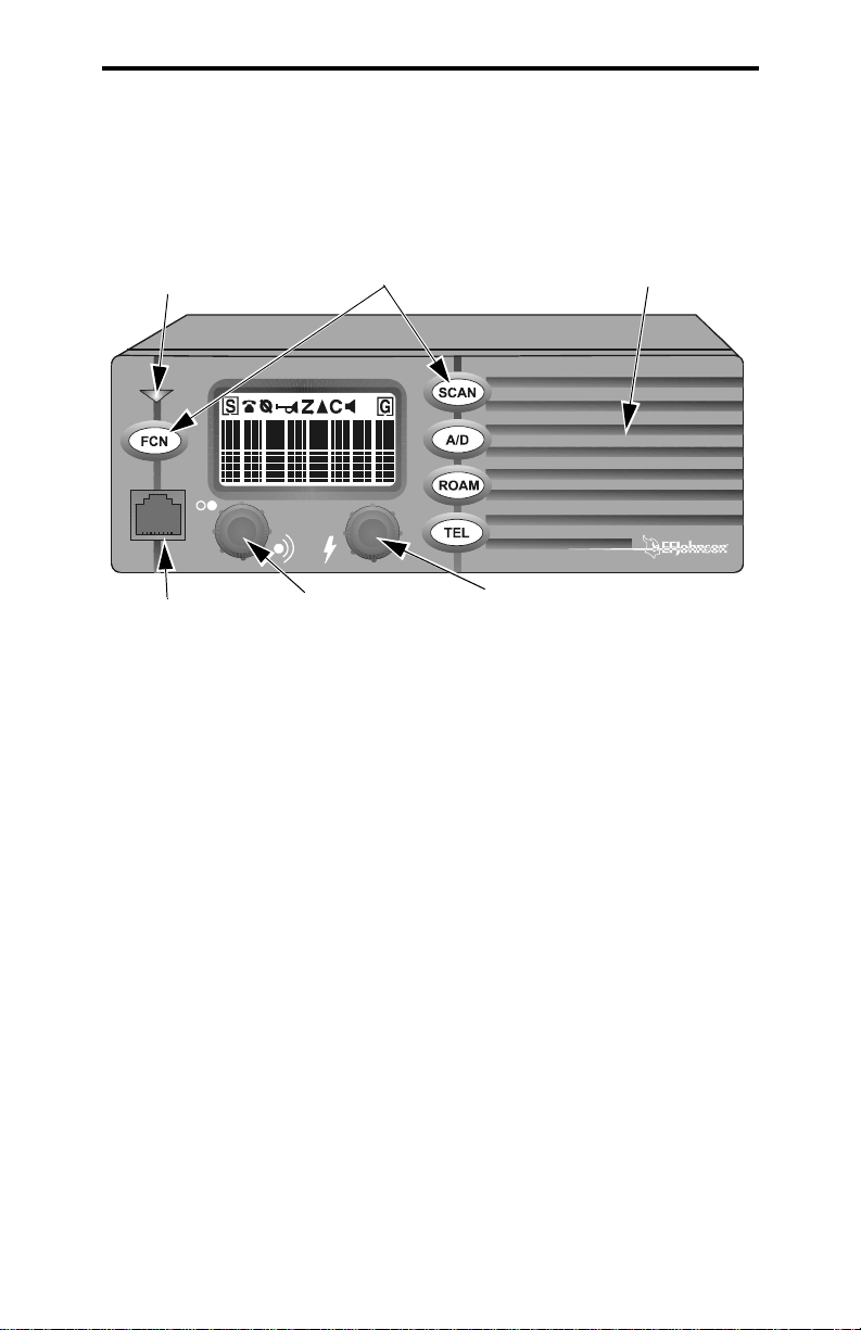
Transmit/Busy
Indicator
Microphone
Jack
Option Switches
On-Off/Volume
Speaker
Select Switch
Front Panel Controls
On-Off Volume - Pressing this knob turns power on and off. The
vehicle ignition switch may also control power as described in
“Power Turn-Off Delay” on page 24. Rotating this knob sets the
speaker volume (see page 15).
Select Switch - Th is switch changes the selected sys tem or group and
is also used for other functions such as selecting parameters in the
menu mode. T o change the system or group, pres s this knob to switch
between the system and group select modes, and then rotate it to
increase or decrease the system or group. Refer to “Selecting the
System and Group” on p age 17 and the FCN switch description which
follows for more information.
Option Switches - The five front panel option switches can be
programmed by your system operator to control the functions which
follow. Refer to the section indicated for more information . T he
keycap usually indicates the function controlled by the switch.
11
Page 12

CONTROLS AND DISPLAY
A/D - Scan list add/delete (see page 38)
BANK - Bank select (see page 20)
EMER - Emergency switch (see page 21)
ENCPT - Encryption select (see page 21)
FCN - Function select (see following description)
HOME - Select home system/group (see page 22)
(Menu) - Menu mode select (see page 33)
AUX - Option select (see page 24)
ROAM - Roam on-off (see page 43)
SCAN - Scan on-off (see page 35)
TEL - Selects telephone group (see “Tel Grp Select” on page 41)
(Blank) - Not used (disabled) or one of above functions
FCN (Function) Switch - This switch, if programmed, selects the
following functions:
Menu Mode Select
Home Sys/Grp Select
Conv Squelch Set
- Press FCN twice (see page 33)
- FCN/press Select switch (see page 22)
- FCN/rotate Select switch (see page 18)
Transmit/Busy Indicator - Indicates the following conditions:
Red
- Transmitter keyed, normal power output
Orange
- Transmitter keyed, power reduced because internal
temperature is high (see page 27).
Green
- Busy conventiona l group (chann el). Refer to “Moni toring
Before Transmitting” on page 44 for more information.
Microphone Jack - C onnection point for the microphone.
Microphone Push-To-Talk (PTT) Switch (Not Shown) - Push-
button on the microphone which is pressed to key the transmitter.
Speaker - The internal speaker is located behind the grille. An
optional speaker can be connected to the external speaker jack located
on the back (see “Speaker Jack” which follows).
12
Page 13
CONTROLS AND DISPLAY
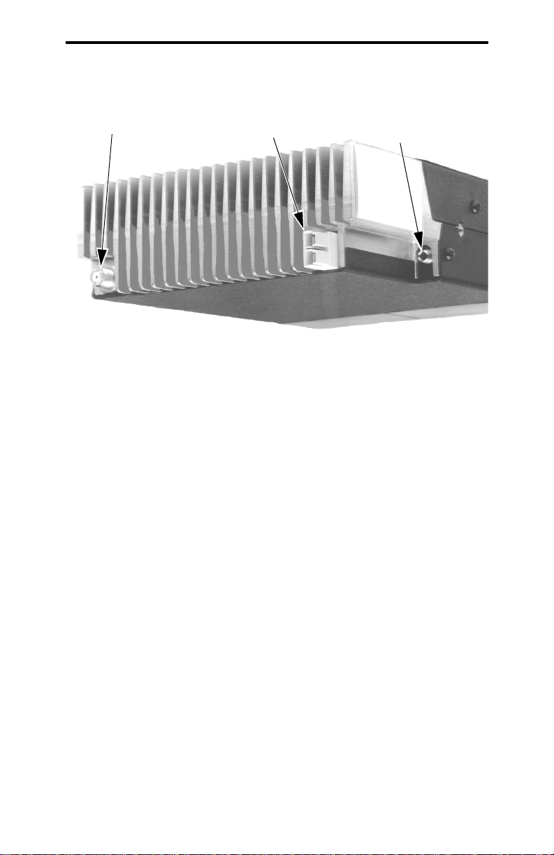
Antenna
Jack
Power
Jack
Speaker
Jack
Rear Panel Jacks and Connectors
Antenna Jack - Miniature UHF jack for connecting the 50-ohm
antenna.
Power Jack - Connection po int for the power c able which attaches t o
the vehicle battery. A nominal 12-volt DC, negative ground power
source is required.
Speaker Jack - Connection point for an optional external 4.7-ohm,
5-watt speaker . The inter nal speaker is automa tically disabled when a
speaker is plugged into this jack.
Accessory Cable (Not Shown) - This optional cable is used to
connect functions such as ignition switch sense to the transceiver.
13
Page 14
CONTROLS AND DISPLAY
System Scan
List
16-Character
Message Area
Phone/
UID Grp
Encryption
Scan
Horn Alert
Call
Option
Group Scan
List
Monitor
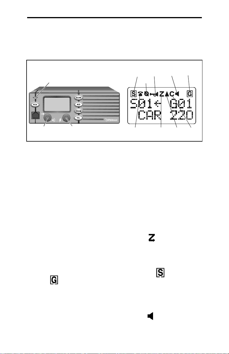
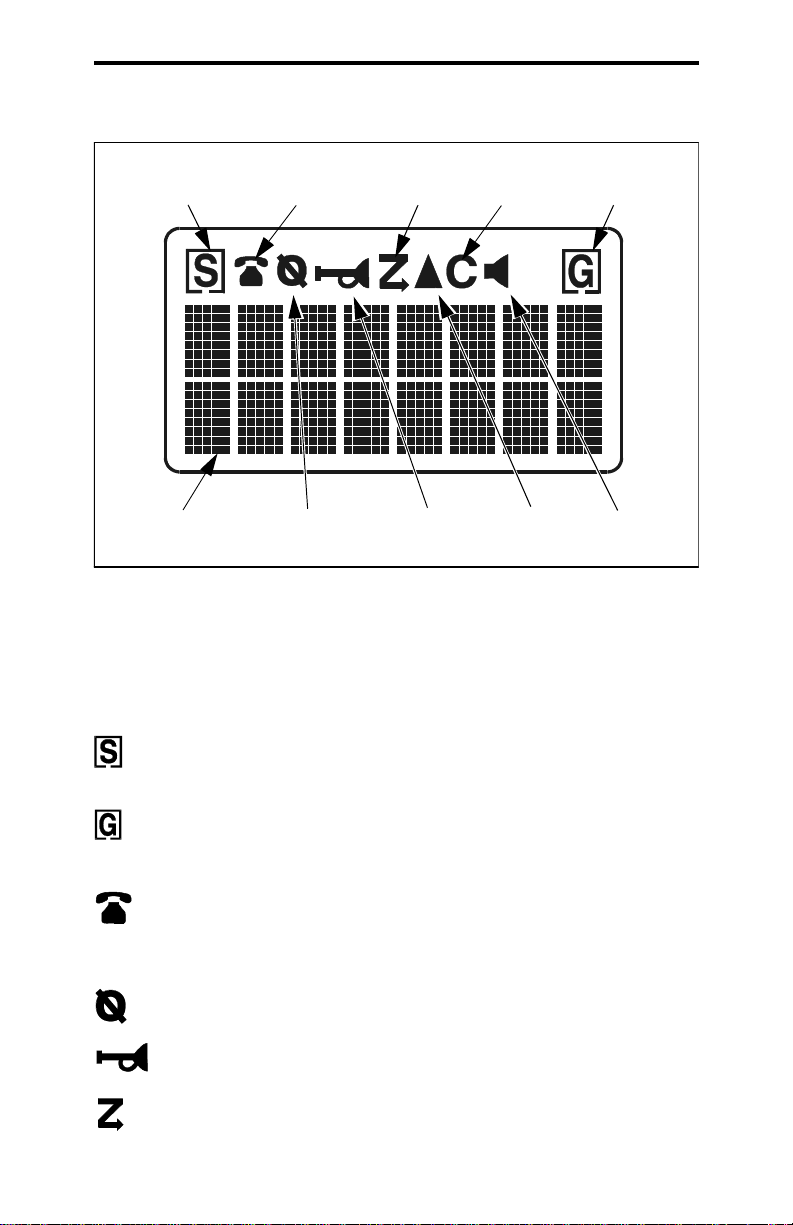
Display Description
16-Character Message Area - Indicates the selected system and
group (see page 16) and also error conditions and status information.
- Indicates that the displayed system is in the scan list and
scanned normally (see page 38).
- Indicates that the displayed group is in the scan list and
scanned normally (see page 38).
- Indicates that the selec te d grou p is pr ogr amme d for tel ep hone
calls. With LTR-Net operation, it also indicates that the group is
programmed for Auxiliary calls (see page 42).
- Indicates that optional encryption is enabled (see page 21).
- Indicates that the horn alert is enabled (see page 23).
- Indicates that scanning is enabled (see page 35).
14
Page 15

GENERAL OPERATION
- Indicates that an option controlled by the AUX switch or
OPTION menu parameter is e nabled (see page 24).
- Indicates that a call has been received on a group programmed
for a call indicator (see page 21). To turn this indication off, press
any key.
- Indicates that th e m oni tor mode is enabled. This mode disable s
Call Guard squelch and other squelch control features so that all
messages are heard on conventional systems (see page 44).
GENERAL OPERATION
Power-Up Sequence
When power is turned on, the backlight turns on, all segments
in the display are momentarily enabled, and the last seven digits of
the transceiver part number are very briefly displayed. A beep then
sounds (if tones are enabled) and the transceiver is operational.
Determining Volume Level
The relative volum e setting can be determined by noting the
position of the index on the volume knob. You may also be able to
enable a reference tone or background noise for use in setting the
volume. Proceed as follows:
• If key press tones are enabl ed, a short tone soun ds when an option
switch is pressed or the Select switch is pressed or rotated.
• If a conventional syst em is selected, take the mi crophone off-hook
and if someone is using the channel, voice is heard. If no one is
using the channel, the squelch control can be adjusted counter-
clockwise as described in “Setting Squelch Control” on page 18
and noise is heard. It is not possible to unsquelch the transceiver
in this manner when an LTR-Net or LTR system is selected.
15
Page 16
GENERAL OPERATION
Backlight Operation
The display and keypad backlight can be controlled by the
BACKLG T menu parameter (see page 33). The three states that can be
selected are Bright, Dim, and Off. If this menu parameter is not selectable, the backlight is fixed in one of these states by programming.
System/Group Display Modes
The selected system and group are displayed using either a
Numeric or Alpha display mode. The display mode is selectable if
the S/G DISPL menu parameter is available (see page 33). Otherwise, it is fixed in one of these modes by programming.
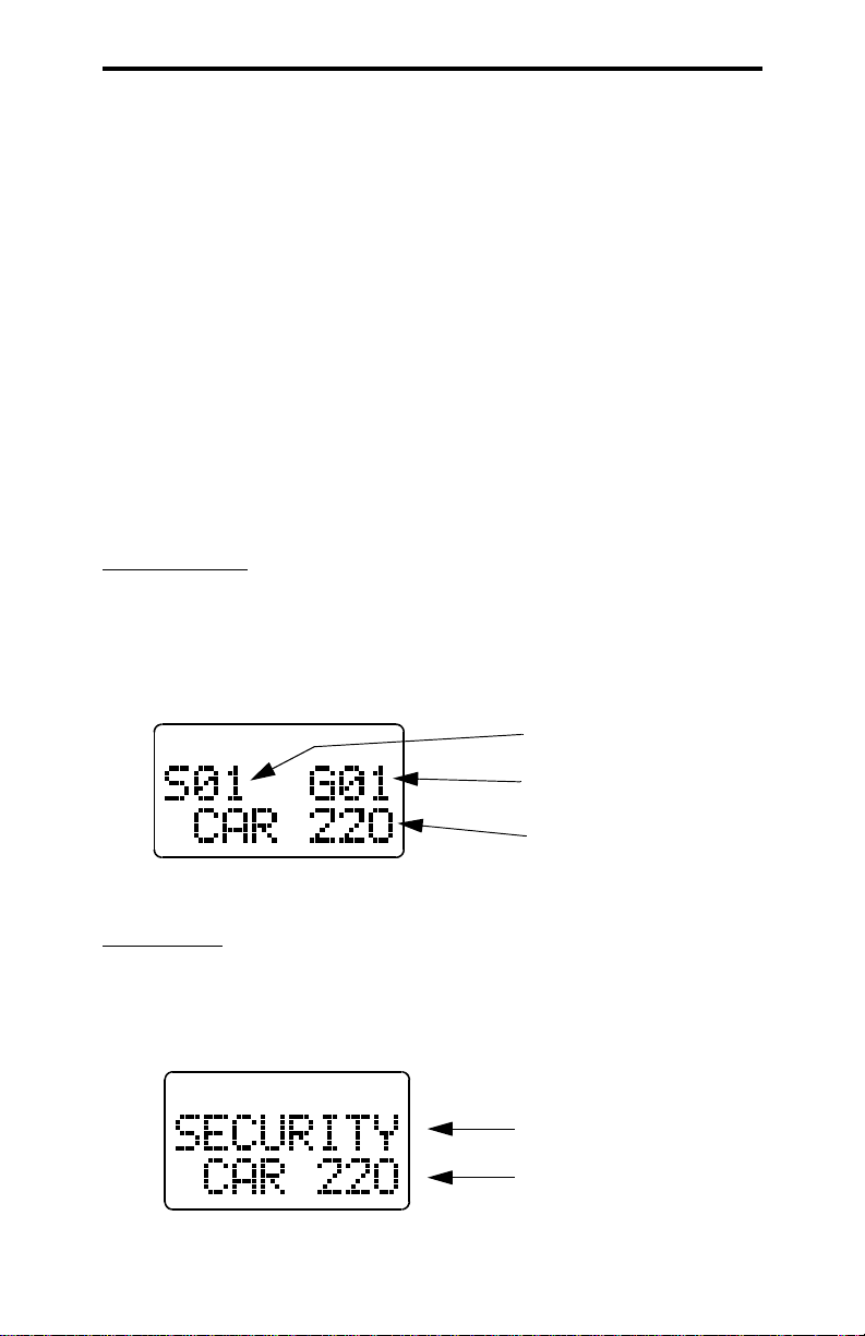
Numeric Mode
- In this mode the selected system and group
numbers are displayed on t he top l ine as Sxx and Gxx, an d th e group
alpha tag is displayed on the bottom line. For example, System 1,
Group 1 (CAR 220) is displayed as follows. The system alpha tag is
not displayed in this mode.
System Nu mber
Group Number
Group Alpha Tag
Numeric Display Mode
Alpha Mode
- In the alpha mode, the system alpha tag is displayed
on the top line and the group alpha tag is displayed on the bottom
line. For example, a “SECURITY” system and “CAR 220” group
are displayed as follows. The system and group numbers are not
displayed in this mode.
System Alpha Tag
Group Alpha Tag
16
Alpha Display Mode
Page 17
GENERAL OPERATION
Selecting the System and Group
The front panel Select switch is used to change the system and
group. Pressing this switch toggles between the system and group
select modes, and rotating it increases or decreases the system or
group.
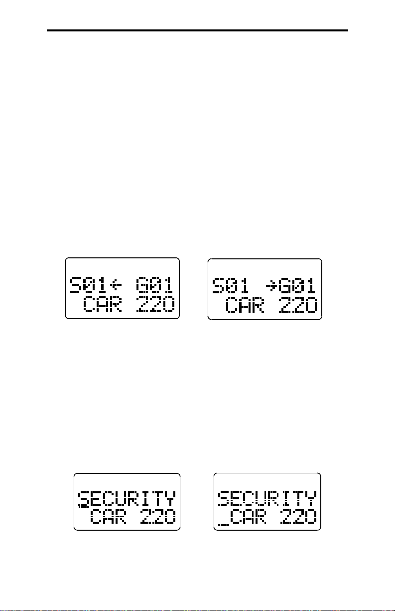
In the Numeric display mode (see preceding description), the
system select mode i s i ndi ca te d whe n t he arrow points to “Sxx”, and
the group select mode is indicated when it points to “Gxx” (see
following illustration).
System Select
Mode
Group Select
Mode
Select Mode Indication With Numeric Display
In the Alpha Tag display mode, the system select mode is indicated by an underline in the left-most character position of the
system alpha tag. Likewi se , th e gr oup select mode is indicated by an
underline in the left-most position of the group alpha tag (see
following illustration).
System Select
Mode
Group Select
Mode
Select Mode Indication With Alpha Tag Display
17
Page 18

GENERAL OPERATION
The current mode remains selected until the menu mode is
selected or transceiver power is cycled. The programmed default
mode is then selected if applicable.
Setting Squelch Contro l
NOTE: This sets the squelch level used for conventional calls. The
squelch level for L TR-Ne t and L TR cal ls i s preset and not affected by
this adjustment. For more information on operating modes, refer to
page 19.
If conventional systems are programmed, the squelch level can
be set if the FCN option switch is enabled. Proceed as follows:
1. Select a convent ional system and a group that i s not busy . T ake the
microphone off-hook to enable monitoring.
2. Press the FCN switch and then rotate the Select switch as you
would a normal squelch control. Rotate it counterclockwise until
receiver noise is heard and then clockwise slightly past the point
where the noise mutes. The squelch adjust mode is indicated by
“SQUELCH” on the upper line of the display, and the relative
squelch level is indicated by a bar graph on the bottom line.
3. To select the current level and exit this mode, press the Select
switch. This also occurs automatically 2 seconds after no change
is made or 8 seconds after no activity.
4. If both narrow and wide band channels are used, perform this
adjustment on both types be cause separate settings are maintained.
NOTE: Some readjustment may be required if weak messages are
not heard or unsquelching occurs when no messages are present.
Microphone Off-Hook Detect
Microphone off-hook detection can be disabled by programming. Taking the microphone off-hook then does not disable scan-
18
Page 19

GENERAL OPERATION
ning (see page 35) or enable conventional channel monitoring (see
page 44).
LTR-Net, LTR, and Conventional Operation
Introduction
Each selectable system can be programmed for LTR-Net, LTR,
or conventional op er ati on. The type of operation that is p rog rammed
is determined by the radio equipment being used by your system
operator. There are only a few differences in operation that are of
concern to the user. These differences are described in the following
information and also noted elsewhere in this manual as required.
LTR-Net and LTR Operation
The LTR-Net and LTR modes provide automatic channel selection and monitoring before transmitting. Special tones and display
messages indicate busy and out-of-range conditions, and telephone
calls can be placed almost as conveniently as with your home
telephone.
Selecting a system selects a collection of up to 99 groups, and
selecting one of these groups selects an ID code which determines
the type of call (standard group, telephone, or special). In addition,
with standard group calls, it determines the specific mobile or
mobiles being called and what calls are received. Priority groups
may also be programmed wh ich allow a dditi onal ca lls t o be rec eived
(see page 41).
The LTR-Net operating mode provides the most operating
features. Exclusive LTR-Net features include roaming and auxiliary
calls such as Unique ID and Directed Group. Calls can be made to
mobiles in your site or some other site. LTR-Net and LTR features
are described starting on page 40.
19
Page 20

GENERAL FEATURES
Conventional Operation
In the conventional mode, selecting a system selects a specific
radio channel, and selecting a group selects the special Call Guard
squelch coding (if used) and other unique channel parameters such
as call indicator operation. The Call Guard coding determines the
mobile or group of mobiles being called and also the mobiles from
which calls are received (see “Call Guard Squelch” on page 47).
In the conventional mode, a busy con dit io n is detected automatically if the Transmit Disable On Busy feature is used. Otherwise, it
must be detected manually as described in “Monitoring Before
Transmitting” on page 44. Busy and no access conditions cannot be
detected with conventional signaling, so are not indicated by special
tones or display messages. Refer to “Operation At Extended Range”
on page 54 for information on how to determine if an out-of-range
condition may exist.
GENERAL FEATURES
Bank Select
A bank is a collection of selectable systems that have been set
up for a specific application. For example, one bank could be
programmed for operation in Minneapolis and another for operation
in Milwaukee. Each bank is identified by a unique alpha tag, and up
to sixteen banks can be programmed.
Banks are selected by the BANK SEL menu parameter or
BANK option switch. In the menu mode (see page 33), rotate the
Select switch to display “BANK SEL” on the top line and the
current bank is then displayed on the bottom line. Press the Select
switch to change the bank. If using the option switch, when “BANK
SEL” is displayed on the top line, simply press the Select switch to
select the desired bank. If neither the menu parameter nor the option
switch is available, banks are not selectable.
20
Page 21

GENERAL FEATURES
Call Indicator
The call indicator is “C” in the upper part of the display (see
following illustra ti on) . The pu rpos e of this indication is to show that
a call was received while you were away from the vehicle. Individual groups can be programmed for this feature and it then turns
on when a call is received on one of those groups.
Call
Indicator
This indicator is turned off by pressing any button or cycling
transceiver power. If scanning and the “Last Received” configuration is programmed (see “Transmitting In The Scan Mode” on
page 39), the system and group of the last call are displayed. Otherwise, the currently selected system/group is displayed.
Emergency Switch
If the EMER option switch is programmed (see page 33), it is
used to quickly select the emergency system/group that has been
programmed in the current bank. The emergency call must then be
manually transmitted by pressing the PTT switch (automatic transmissions do not occur). Scanning continues if it is enabled, and calls
are received normally on other systems and groups if appli cab le.
Encryption
Encryption is an optional feature that prevents conversations
from being monitored by casual eavesdropping and analog
scanners. It does this by encrypting your voice so that it can be
understood only by someone using a transceiver equipped with a
similar encryption device.
Encryption is enabled and disabled by the ENCRYPT menu
parameter or ENCPT option switch (see page 33). If this menu
21
Page 22

GENERAL FEATURES
parameter or option switch is not available, encryption may be fixed
in the enabled mode by programming. When encryption is enabled,
is indicated in the upper part of the display (see page 14).
To transmit an encrypted call, encryption must be enabled as
just described and the selected group must be programmed for
encryption. Encrypted calls are always received regardless of the
currently selected encryption mode and group programming (if the
radio is equipped with encryption). When transmitting an encrypted
call, wait approximately 1 second before speaking. This gives the
receiving transceiver time to establish synchronization which
ensures that all of the first word is received. If the proceed tone is
used and an encrypted call is transmitted, two beeps instead of one
sound and the tone is automatically delayed for the required time.
Function (FCN) Switch
If an option switch is pr ogrammed for FCN (f unction) , it selects
the following features. When the function select mode is active,
“FCN” is displayed on the lower line of the display. This mode is
automatically exited 2 seconds after a change is made or 8 seconds
after no activity.
Menu Mode Select
- Pressing FCN twice or the Menu option switch
selects the menu mode as described on page 33.
Home System/Group Select
- Pressing FCN and then the Select
switch or the HOME option swi tch selec ts the home sy stem/group as
described in the next section.
Squelch Adjust
- Pressing FCN and then rotating the Select switch
with a conventional system selected sets the squelch level as
described on page 18.
Home System/Group Select
T o selec t the prepr ogrammed Home sys tem/group, s imply press
the FCN swi t ch and then the Select switch. Alternatively, press the
22
Page 23

GENERAL FEATURES
HOME option switch if it is programmed. The Home system/group
is then displayed and it becomes the selected system/group. If no
home system/group or FCN or HOME option switch has been
programmed, this functi on i s no t a vai la ble . A di fferent home system/
group can be programmed for each bank.
Horn Alert
NOTE: The horn alert feature is not be available with some early
models.
If this feature has been installed by your system operator, it
activates an external alert such as the vehicle horn or lights when a
call is received on a group programmed for horn alert. When the
horn alert is enabled, is displayed as shown in the following
illustration.
Horn Alert
Enabled
When enabled, the horn alert pulses on and off for 1-8 cycles
and then goes back to the disabled state. To change the currently
selected horn alert mode, the HRN ALRT menu param eter can be
used if available (see page 33).
The horn alert is programmed to operate in the manual or automatic mode (see descriptions which follow). If the ignition switch
does not control transceiver power, only the front panel power
switch affects operation when applicable. Refer to “Power Turn-Off
Delay” on page 24 for more information.
Manual Off/On Mode
The horn alert mode does not change when power is turned on
and off by either the ignition switch or power switch. Therefore, the
horn alert is entirely controlled by the HRN ALRT menu parameter.
23
Page 24

GENERAL FEATURES
Auto Off/On Mode
Ignition Switch - The horn alert always turns off when the ignition
switch is turned on, and al ways turns on when the ignition switch is
turned off (if the re is a turn-off delay).
Power Switch
- The horn alert always reverts to the off condition
when power is turned on by the power switch.
NOTE: The preceding automatic operation overrides any mode that
may have been selected by the HRN ALRT menu parameter.
Option Select
The AUX switch or OPTION menu parameter can be used to
control an accessory that may have been installed by your system
operator. The enabled condition is indicated by in the display.
Power Turn-Off De l ay
Your transceiver may have been installed so that the vehicle
ignition switch as well as the front-panel power switch control transceiver power. If this is the case, both the ignition switch and the
front panel power switch must be on for transceiver power to turn
on.
When the igni tion switch controls power, turn-off delays of
Immediate, 10, 20, 30, 40, or 50 minutes, 1, 2, 4, 8, 10, 12, or 16
hours or Forever can be programmed. The delay can be overridden
at any time by turning power off using the front-panel power switch
or turning the ignition switch back on.
A power turn-off del ay allows f eatures such as the call indicat or
to remain activ e for a time after the ignition switch is turned off. At
the same time, advantages of ignition switch control are utilized
such as preventing battery discharge that may occur if the transceiver is accidentally left on for an extended period (see page 54).
24
Page 25

GENERAL FEATURES
Proceed (Clear-To-Talk) Tone
This is a short tone that sounds shortly after the PTT switch is
pressed to indicate that the radio system has been accessed and
speaking can begin. The transceiver can be programmed so that this
tone sounds on LTR-Net and LTR systems but not conventional
systems. In addition, this and other tones can be disabled on all
systems by the TONES menu parameter (see “Tone Select” on
page 26) or system operator programming.
On L TR- Net and LTR systems, if the radio system is busy when
making a call, the busy tone sounds instead of the proceed tone and
“BUSY” is indicated on the bottom line of the display. If an access
attempt is unsuccessful, such as because of an out-of-range condition, the intercept tone sounds and “NO ACCES” is indicated in the
display. When the “NO ACCES” condition, the PTT switch must be
released to make another call at tempt. Refer to page 47 for more
information on the busy and intercept tones.
On conventional systems, the Transmit Disable On Busy
feature can be used to automatically perform monitoring (see
page 46). The proceed tone then does not sound if the channel is
busy. Otherwise, the proceed tone (if enabled) sounds on conventional systems even if the channel is busy. If encryption is used, two
tones sound instead of one to indicate that an encrypted call is being
transmitted. With other calls, a standard (single beep) or distinctive
(3-beep) tone may be used. With special and telephone calls, the
proceed tone may sound on only the initial access.
Receive-Only Groups
Any group can be programmed for monitoring only (transmitting is disabled). If the PTT switch is pressed with one of these
groups selected, the intercept tone sounds and “TX DISBL” is
displayed.
25
Page 26

GENERAL FEATURES
Stealth Mode
The stealth mode disables the following tones and indicators so
that they do not reveal t hat you are transmittin g or otherwi se indicat e
your presence. The speaker audi o and display remain enabled in this
mode.
• All tones (see “Tone Select” on page 26)
• The front panel transmit/busy indicator (see page 11)
• Display backlight
The stealth mode can be selected by the STEALTH menu
parameter (see page 33), or is fixed in the on or off mode by
programming. There is no special indication that this mode is
selected except that “On” is displayed under “STEALTH” when it is
selected by the menu mode.
Time-Out Timer
The time-out timer disables the transmitter if it is keyed continuously for longer than the programmed time. It can be programmed
for 0.5 - 5.0 minutes or disabled entirely. If the transmitter is keyed
continuously for lon ger tha n the program med time, th e trans mit ter is
disabled, “TIMEOUT” is indicated on the lower line of the display,
and the intercept tone sounds. The timer and tone are reset by
releasing the PTT switch.
One use of the time-out timer feature is to prevent a repeater
from being kept busy for an extended period by an accidentally
keyed transmitter. It can also prevent possible damage to the transmitter caused by transmitting for an excessively long period.
Tone Select
If the TONES menu parameter is selectable, the tones that
sound can be selected. Otherwise, the tones that sound are fixed by
programming. The following choi ces are available. Refer to page 33
for more information on using the menu mode.
26
Page 27

STANDARD GROUP CALLS
Silent - All tones are disabled.
Keys - Only the Select switch and key press tones are enabled.
Alerts - All tones except the preceding Key Beep tones are enabled.
All - Both the Key Beep and Alert tones are enabled.
Transmitter Thermal Foldback
If the transm itter temperature increases to the point where
damage to the transceiver could result, power is automatically cut
back. When this happens, the transmit indicator on the front panel is
orange instead of red when the transmitter is keyed. After sufficient
cooling occurs, power output automatically returns to the normal
level and the indicator changes back to red. One time when this indication could occur is if you transmit for an extended period.
STANDARD GROUP CALLS
General
Most calls you make are probably the standard group type
described in this section. These calls are between you and another
mobile or control station. The main difference between these calls
and the other types that can be placed is that no number is dialed
using a keypad. The follo wing proc edure ap plies to all three t ypes of
operation (LTR-Net, LTR, and conventional).
Placing a Standard Group Call
1. Turn tran sceiver power on and set the volume as descri bed starting
on page 15. With conventional operation, also make sure that the
squelch is properly set as described on page 18.
2. Select the system and group of the mobile being called as
described starting on page 17.
3. If a conventional call is being placed, monitor the channel
manually or automatically as described on page 44.
27
Page 28

STANDARD GROUP CALLS
4. Press (and hold) the microph one P TT (pus h-to-talk) swi tch to talk
and release it to listen. Operatio n with LTR-Net, LTR, and conventional calls is as follows:
LTR-Net and LTR Operation
• If the proceed tone is enabled (see page 25), it sounds shortly
after the PTT switch is pressed i f t he radio system was successfully accessed. If it is not enabled, no tone sounds when the
system is successfully accessed. The proceed and other tones
can be disabled as described in “Tone Select” on page 26.
• If the radio system is busy, the busy tone sounds (see page 47)
and “BUSY” is indicated on the lowe r line of the display. Additional access attempts are made as long as the PTT switch
remains pressed.
• If the radio system could not be accessed because of an out-of-
range condition or some other reaso n, the intercept ton e sounds
(see page 48) and “NO ACCES” is indicated on the lower line
of the display. The PTT switch must then be released and
pressed again to make another access attempt.
• When responding, b usy or no access co nditions may also oc cur
the same as when placing a call because the system is
re-accessed for each transmission with these calls.
Conventional Operati on
• If the channe l is busy and th e Tran smit Disable On Bus y feature
is programmed (see page 46), “DSBL BSY” is indicated on t he
lower line of the display and the transmitter is disabled. Any
channel activity is heard while the PTT switch is pressed.
• Otherwise, busy and out-of-range conditions are not indicated
and speaking can begin when the PTT switch is pressed (if the
channel is not busy). If the proceed tone is enabled on conventional systems, it indicates when speaking can begin but does
28
Page 29

TELEPHONE CALLS
not indicate that the radio system has been successfully
accessed.
5. When the call is complete, place the microphone back on-hook.
Receiving a Standard Group Call
1. Select or scan the system and group programmed for the call you
want to receive (see page 35 for scan information).
2. When the message is received, the display usually changes to the
system and group of the call. Take the microphone off-hook and
press the PTT switch to talk and release it to listen. If scanning, a
response may not automatically occur on the group of the call.
Refer to “Transmitting In The Scan Mode” on page 39 for more
information.
TELEPHONE CALLS
General
NOTE: Telephone calls can be placed and received only if that
service is available to you and your transceiver has been
programmed appr opr iately. In addition, a microphone equipped with
a telephone keypad is required to dial the telephone number.
The telephone calling feature allows you to place and receive
telephone calls using your transceiver. The following information
describes how these calls are made with LTR-Net and LTR operation. If you can make telephone calls with conventional operation,
the procedure may be somewhat different and your system operator
will then provide additional information. Proceed as follows:
Placing Telephone Calls
1. Turn tran sceiver power on and set the volume as descri bed starting
on page 15. Select the group programm ed for telephone calls. To
29
Page 30

TELEPHONE CALLS
quickly select the teleph one group in the current system, press the
TEL option switch as described on page 41. When a group
programmed for telephone calls is selected, is displayed.
2. T o obtain the dial tone, briefly press t he P TT switch. If the proceed
tone is used (see page 25), press the PTT switch until this tone
sounds. If a dial tone is then heard, proceed to step 4. Busy or no
access conditions may also be indic ated the s ame as desc ribed for
standard group calls on page 28.
3. With th e dial tone soundi ng, dial the number using the 0-9 keys on
the microphone keypad. I f the microphone has a memory , you may
also be able to recall the number from memory. The PTT switch
does not need to be pressed while dialing if the transmitter automatically keys. If too much time elapses betw een digits, t he call is
terminated.
4. After the number is dialed, release the PTT switch (if it was
pressed). With LTR-Net operation, a short tone then sounds to
indicate that the number was accepted by the system. Landside
ringing (or a landside busy condition) should then be heard.
5. When the other party answers, pr ess th e PTT switch and respond.
The PTT switch must be pressed to talk and released to listen the
same as with mobile-to-mobile calls.
6. When the c all is finished, it should be terminated. This is usually
done by transmitting either the # or # characters, and termina-
X
tion is indicated by three beeps. Terminating the call in this
manner prevents extra billing that may occur while the system
automatically detects the end of the call.
Receiving a Telephone Call
1. Select or scan the system and group programmed for telephone
calls. To quickly select the te lephone group i n the c urren t syst em,
press the TEL option s witch. When a telep hone group is sel ecte d,
is displaye d.
30
Page 31

LTR-NET AUXILIARY CALLS
2. When “ringing” is heard, press the PTT switch and respond. The
P TT switch must be pr essed t o talk a nd released to lis ten the same
as with standard calls.
3. When the call is finish ed, it should be termina ted as in step 6 of the
preceding section.
Landside-Originate Telephone Calls
If telephone calls can be placed, then it is usually possible to
receive telephone calls from a landside telephone. With some radio
systems, each mobile is assigned a unique telephone number so that
it can be dialed direc tl y. With others, the number of the radio system
is dialed and then when a tone sounds, the number specifying the
mobile being called is dialed using a tone-type telephone. The
mobile user hears “ringing” when the call is received. Contact your
system operator fo r t he numb er to d ial and mo re inf orma tion o n how
to place these calls.
LTR-NET AUXILIARY CALLS
General
The LTR-Net Auxiliary calls include Unique ID and Directed
Group calls (see page 42). Unique ID calls are to specific mobiles,
and Directed Group calls are to specific talk groups. These calls can
be placed to mobiles in your site or some other site that is part of
your radio network.
As with telephone calls, a special number must be dialed to
place these calls. Therefore, a microphone with a telephone keypad
is required. The number dialed is 1-10 digits long, and is provided
by your system operator. Other requirements to place these calls are
you must be authorized to make them and your transceiver must be
appropriately programmed.
31
Page 32

LTR-NET AUXILIARY CALLS
Placing LTR-Net Auxiliary C alls
1. Select the LTR-Net system and group programmed for Auxiliary
calls. When a group programmed for the se calls is select ed, is
indicated in the upper part of the display. The group alpha tag
displayed on the lower line may also indicate when one of these
groups is selected.
2. To obtain a dial tone, briefly press the PTT switch. If the proceed
tone is enabled, hold the PTT switch until this tone sounds. Busy
or no access conditions may also be indicated the same as
described for standard group calls on page 28.
3. A 1-10 digit number is dialed which specifies the destination of
the call. Refer to step 3 on page 30 for more dialing inform ation.
4. A tone then sounds to indicate that the call was accepted by the
system. If this tone does not sound, an unauthorized or incorrect
number may have been d ial ed . The call then proceeds as follows.
If all system resources are busy, the call is placed in a queue as
described in “Busy Queuing” on page 42.
Unique ID Call - Ringing is heard to indica te that th e other trans ceiver is being rung. If there is no answer, ringing automatically
stops after sever al rings and the c all is term inated. When the other
party answers, respond as with a standard call.
Directed Group Call - A second tone sounds to indicate that the
path is complete and speaking should begin. No ringing occurs.
5. When the call is complete, it s hould be termina ted by transmit ting
either the # or # characters. Three beeps indicate that the call
X
has been terminated.
Receiving Auxiliar y Calls
To receive a Unique ID call, all that is required is that an LTRNet system containing a group programmed for those calls be
32
Page 33

OPTION SWITCHES AND MENU MODE
selected. To receive a Directed Group call, the group of the call may
need to be selected or scanned. A Unique ID call is indicated by a
“ringing” tone similar to telephone calls, and a Directed Group call
is indicated by the caller’s voice the same as with standard group
calls.
The transceiver may be programmed so that responses always
occur on the last selected group. In this case, the group may need to
be manually changed to respond to these calls (see “Transmitting In
The Scan Mode” on page 39). Unique ID and Directed Group calls
can also be placed from a landside telephone. The same number s are
dialed as when the call is mobile originated. Contact your system
operator fo r more information.
OPTION SWITCHES AND
MENU MODE
Option Switches
All five option switches on the front panel are programmable
by your system operator. The available option switch functions are
indicated by an entry in the “Option Switch” column of the table on
the next page. More information on each function can be found on
the page indicated in this table. Some functions may be controlled
by both the menu mode and an option switch. The function
controlled by each switch may be indicated on the switch key cap.
Some switches may not be used or may have a blank key cap.
Menu Mode Introduction
The menu mode is selec te d by pre ssing the Menu option switch
(the label may vary) or the FCN switch twice. If neither of these
switches is programmed, the m enu mode is not available. Functions
which can be controlled by the menu mode a re indicated by an entry
in the “Menu Items” column o f the preceding table. More inf ormation on each function can be found on the page indicated in this
33
Page 34

OPTION SWITCHES AND MENU MODE
table. Some parameters may not be displayed because they are not
used or are in a fixed state or controlled by an option switch. Calls
cannot be received or transmitted while the menu mode is selected.
Menu Mode and Option Switch Functions
Function Menu Items
Option
Switch
See Descrip.
on Page
Add/delete (scan list prg) A/D 38
Backlight adjust BACKLGHT 16
Bank select BANK SEL BANK 20
Display mode select SG DISPL 16
Emergency sys/grp select EMER 21
Encryption on-off ENCRYPT ENCPT 21
Function select FCN 22
Home system/group
select
HOME 22
FCN then
press Sel Sw
Horn Alert on-off HRN ALRT 23
Menu mode select MENU 33
FCN (twice)
Option select OPTION AUX 24
Roaming on-off [1] ROAMING ROAM 43
Scan on-off SCAN 35
Scan type select SCN TYPE 35
Scan continue on-off SCN CONT 39
Scan list save mode SCN SAVE 38
Stealth mode select STEALTH 26
Squelch adjust FCN then
18
rotate Sel Sw
Telephone group select TEL 41
Tone type select TONES 26
NOTES: Functions left blank are not available.
[1] Available with LTR-Net operation only.
34
Page 35

SYSTEM AND GROUP SCANNING
Using Menu Mode
1. T o select the menu mode, press th e Menu switch or FCN FCN (the
FCN switch twice). The top line of the display indicates the function being edited, and the bottom line indicates the current status
of that function (see following illustration).
Function
Status
2. T o d ispla y the vari ous f uncti ons t hat a re co ntrol lable by t he menu
mode (top line indicatio n), rota te the Sel ect switc h. The curr ently
selected status of that function is displayed on the bottom line.
3. To change the selected status, press the Select switch. The selections displayed for each menu function are shown on page 52.
4. The selected status conditions for the various functions are saved
when the menu mode is exited in one of the following ways:
• Pressing the FCN switch again
• Pressing the PTT switch
• Automatically when time-out occu rs 2 seconds after a chang e is
made or 8 seconds after no changes are made.
SYSTEM AND GROUP SCANNING
General
Introduction
The scan feature monitors, in sequence, the programmed
systems and/or groups in the scan list. When a message is detected
that the transceiver is programmed to rece ive, sca nning stops an d the
35
Page 36

SYSTEM AND GROUP SCANNING
message is received. Shortl y afte r the mess age is complete , scanni ng
resumes (unless it h as been di sabled ). Scanning is sequen tial throu gh
the programmed systems and groups. System and group scanning
operate as follows:
System Scanning
- Detects calls on all systems that are in the
system scan list. When system scanning is not used, calls are
detected on only the currently selected system.
Group Scanning
- Detects calls on the selectable groups in the
current or scanned systems that are in the group scan list. When
group scanning is not used, calls are detected on only the
currently selected group or if system scanning, on the last
selected group of each system.
Scan On-Off
System and/or group scanning are turned on and off by the
SCAN option switch. When system and/or group scanning is
enabled by this switch, is indicated in the display (see following
illustration). Then when system or group scanning is actually occurring, a scrolling underline is displayed under each character in the
upper line of the display. The microphone must be on-hook for scanning to occur (unless off-hook detection has been disabled as
described on page 18).
System Scan List Group Scan List
36
System or Group
Scanning Selected
System or Group
Scanning Occurring
Page 37

SYSTEM AND GROUP SCANNING
Scan Types
The type of scanning selected is determined by the menu mode
SCN TYPE parameter (see page 33). If it is not selectable, the type
of scanning is fixed b y programming . The availa ble scan t ypes are a s
follows.
SYSTEMS - Both system and group
GROUPS - Group scanning only
OFF - Both types disabled (SCAN switch non-functional)
If the SCAN option switch is not programmed, the selected
mode is always enabled. If both the switch and SCN TYPE menu
parameter are disabled, the scan mode and type are fixed by
programming. The selected system and group can be changed while
scanning using the Select switch in the normal manner. Scanning
resumes shortly after the change is made.
When a call is received in the scan mode , the display cha nges to
the system and group of the call. Programming determines if this
change is temporary or permanent, and if a response occurs on the
system/group of the call or the selected system/group. Refer to
“Transmitting In The Scan Mode” on page 39 for more information.
LTR-Net Mode Scanning
When system scanning with an LTR-Net system selected and
roaming disabled, only the LTR-Net systems i n the scan list that
access the site of the selected system are scanned. LTR and conventional systems are not scanned.
When system scanning with roaming enabled, registration on
other sites occurs normally and scanning operates as just described.
However, if the current LTR-Net site is lost and no other LTR-Net
site can be located, the LTR and conventional sy stems in the s can list
are also scanned. If an LTR-Net site is again de tected, reg istration on
that site occurs and the LTR and conventional systems are no longer
scanned. This can provide uninterrupted operation in areas which
have not been converted to LTR-Net operation.
37
Page 38

SYSTEM AND GROUP SCANNING
LTR and Conventional Mode Scanning
When an LTR or conventional system is selected with system
scanning enabled and roaming disabled, scanning is sequential
through only the LTR and conventional systems in the scan list
(LTR-Net systems are not scanned). If roaming is enabled, all three
system types are scanned as described in the preceding LTR-Net
description. Therefore, LTR and conventional systems are not
scanned while on LTR-Net site.
Scan List Programming
General
NOTE: The selected (displayed) system and group are always
scanned even if they have been deleted from the scan list.
The system and group sca n l is ts ar e pr ogr ammed u si ng t he A/D
(add/delete) option switch. Pr essing this switch chang es the st atus of
either the displayed system or group, depending on whether the
system or group select mode is active. This is the same select mode
used for system and group selection as described on page 17. For
example, to change the scan list statu s of the dis playe d system, pre ss
the Select switch if necessary so that the system select mode is indicated and then press the A/D switch.
The displayed system is in the scan list and scanned normally
when is displayed. Likewise, the displayed group is in the scan list
and scanned normally when is displayed (see preceding illustration). Deleting a system only temporarily deletes the groups associated with that system. When a system is added back into the scan list,
the original group scan list is again active.
Systems and groups can be deleted from the scan list while
listening to a message on the system or group by pressing the A/D
switch in the normal manner. Scanning resumes shortly after the
system or group is deleted. Scan list programming is not available if
the A/D switch is not programmed.
38
Page 39

SYSTEM AND GROUP SCANNING
Saving Scan List
If the menu mode SCN SAVE parameter is available, you can
select if scan list changes are saved. If “On” is selected, changes are
saved as they are made and the scan list is the same when power is
turned on. Conversely, if “Off” is selected, they are not saved and the
default scan list status of all systems and groups is reselected when
power is turned on. If the menu SCN SAVE parameter is not selectable, the scan list save mode is fixed in one of these states.
Scan Delay and Continue Timers
When a message is received or transmitted while scanning, there
is a short delay before scanning resumes. The delay after receiving a
call prevents another message from being received before a response
can be made. Likewise, the delay after transmitting a call ensures that
you hear a response to your call instead of another message occurring
on some other system or group. Scanning does not resume if it has
been disabled, such as by taking the microphone off-hook.
There is also a scan continue timer that may be programmed.
This timer controls the maximum time that a call is received before
scanning resumes. Times up to 60 seconds can be programmed. This
prevents scanning from being delayed for long periods by lengthy
calls. If the menu SCN CONT parameter is selectable (see page 33),
this feature can be turned on and off.
Transmitting In The Scan Mode
General
When the transmitter is keyed in the scan mode, programming
determines if the transmission occurs on the last selected or last
received system/group. The display usually indicates the system/
group on which a transmission would occur. The exceptions are
noted in the following information. The three programmable configurations are as follows.
39
Page 40

LTR-NET AND LTR FEATURES
Last Selected - Transmissions always occur on the system/group
that was last selected by the Select switch. Therefore, the display
may not indicate the system/group on which a response occurs. To
respond to a call not on the selected system/group, first select the
system/group of the call using one of the following methods:
• Select it manually using the Select switch.
• Before scanning resumes, exit the scan mode by pressing the
SCAN switch. The system/group of the call then becomes the
selected system/group and it is not necessary to change it
manually.
Last Received - The selected system/group changes to the system/
group of a call. Therefore, you can always respond to a call without
having to manually change the system/group. To return to the previously selected system/group, it must be manually selected using the
Select switch.
Temporary Last Received - The system/group changes to the
system/group of a call for only the duration of the scan delay period
(see page 39.) Then when the delay expir es and scanni ng re sumes ( if
it is not disabled), the selected system/group is again displayed.
Therefore, you can respond to a call without changing the selected
system/group as long as you do so before scanning resumes.
LTR-NET AND LTR FEATURES
Transmit Inhibit
The Transmit Inhibit feature prevents the transmitter from
keying if the mobile you are calling is busy with another call. When
the transmitter is disabled by this feature, the intercept tone sounds
and “TX INHIB” is displayed (see following illustration). To make
another call attempt, the PTT switch must be released and pressed
40
Page 41

LTR-NET AND LTR FEATURES
again. However, you may want to wait a few seconds before making
another attempt because a timer must time out before another
attempt will be successful. A similar Transmit Disable On Busy
feature is available on conventional systems (see page 46).
Calls on Priority ID Codes
With LTR-Net and LTR systems, each selectable group is
programmed with a receive priority number. If a call with a higher
priority is de tected while re ceiving a call, the current call is immediately dropped and the higher priority call is received. System or
group scanning does not need to be enabled for this to occur. Some
groups, such as those used to make telephone calls, may be
programmed as not interrupt ible so t hat cal ls on those groups are not
interrupted by other calls.
The system/group of the higher priority call is displayed while
it is received. The programming of the Last Selected/Last Received/
Temporary parameter described on page 39 determines if the change
is temporary or permanent and if a response occurs on the displayed
or last selected system/group.
Telephone Group Select
If the TEL option switch is programmed (s ee page 33), it can be
used to quickly select the group programmed for telephone calls in
the current system. When a telephone group is selected, is
displayed (this icon is also displayed if an LTR-Net Auxiliary call
group is selected). If more than one group is programmed for telephone calls, the first higher numbe red telephone gro up is se lecte d. If
there is no telephone group or a conventional system is selected,
“NO PHONE” is displayed and an error tone sounds.
41
Page 42

LTR-NET FEATURES
LTR-NET FEATURES
NOTE: Other LTR-Net features are described starting on page 40.
LTR-Net Standard and Special Calls
The LTR-Net Special and Auxiliary calls are shown below.
Refer to the descriptions which follow for more information.
Special
Standard Group Calls
Telephone
Auxiliary
- Standard group calls are b etween two mobiles
Unique ID
Directed Group
or between a mobile and a control station. To place these calls in the
LTR-Net or L TR mode, si mply select the desired group and press the
PTT switch. The procedure for placing and receiving these calls is
described starting on page 27.
T elephone Calls
- These calls allow y ou to make telephone ca lls using
your transceiver, and they are described starting on page 29.
Auxiliary Calls
- As shown in the preceding illustration, Auxiliary
calls include Unique ID and Directed Group calls. Unique ID calls
allow calls to be placed to speci fic mobi les, and Directed Group cal ls
allow calls to be placed to specific talk groups. Auxiliary calls are
described starting on page 31.
Busy Queuing
Queuing may be provided by t he radio syste m when plac ing th e
special calls described in the preceding section if system resources
are not available for the call. Standard group calls are not queued.
When a call is placed in a queue, a voice message informs you that
this has occurred. Then when resou rc es bec o me avai l abl e, the cal l is
automatically pl ace d and the normal ringing or other tones are heard
if applicable. If the call cannot be placed in the allotted time, it is
terminated and another message informs you that this has occurred.
42
Page 43

LTR-NET FEATURES
Roaming
LTR-Net radio localities (sites) can be linked together to
provide wide area coverage. Then as you travel from locality to
locality with roaming enabled, calls are automatically ro uted to your
current location. Both standard group and special calls may be
routed to other localities. To utilize the Roaming feature, proceed as
follows:
1. An LTR-Net system must be selected. When an LTR or conven-
tional system is selected, roaming is disabled.
2. Roaming must be enabled by the ROAM option switch or
ROAMING menu parameter (see page 33) if available. When
roaming is enabled and disabled by the option switch, “ROAM
ON” and “ROAM OFF” are momentarily displa yed. If neither the
menu parameter no r option switch is availab le, roaming is fixed in
the on or off mode by programming.
3. Scanning does not need to be e nabled . If it is, an LTR-Net system
must be selected.
When roaming is enabled as just described and the signal from
the current locality becomes weak, the transceiver automatically
begins searching for another locality. While searching is occurring,
“LCL SRCH” is displayed as shown below. Then when a new
locality is locat ed, regis trat ion occ urs an d “LCL SRCH” is no longer
displayed. The displayed system is the next LTR-Net system
programmed with a diffe ren t lo cality that could be accessed, and the
displayed group is usually the group that was displayed before
roaming occurred.
43
Page 44

LTR FEATURES
LTR FEATURES
NOTE: Other LTR features are described starting on page 40.
Standard Group Calls
Standard group calls are between two mobiles or between a
mobile and a control station. To place these calls in the LTR or LTRNet mode, simply select t he desired group and press the PTT switch.
The procedure for placing and receiving these calls is described
starting on page 27.
Telephone Calls
Telephone calls allow you to place and receive calls over the
public telephone system using your transceiver. LTR and LTR-Net
telephone calls are described starting on page 29.
CONVENTIONAL FEATURES
Monitoring Before Transmitting
General
Regulations require that conventional groups (channels) be
monitored before transmitting to make sure that they are not being
used by someone else. If you were to transmit when someone else is
talking, you would probably disrupt their conversation. In the LTRNet and LTR modes, monitoring is p erformed automa tically. In the
conventional mode, it must be performed automatically or manually
as follows.
Automatic Chann el Monitoring
If the selected group is programmed for the Transmit Disable
On Busy feature (see page 46), monitoring is performed
automatically.
44
Page 45

CONVENTIONAL FEATURES
Busy Indicator
If the group is not automatically monitored as just described, it
must be monitored manually. The simplest way to do this may be to
note if a busy condition is indica ted by the fr ont panel multi -functi on
indicator (see page 11). With scanning disabled and the squelch
control properly adjusted (see page 18), note if this indicator is
lighted green. If it i s, a s ig nal i s b eing detected on the selected grou p
(channel) and you should not transmit a message until it turns off.
Monitor Mode
There may be times when the Busy indica tion i s displ ayed even
though no one is using the channel. Monitoring should then be
performed using the monitor mode. This mode is enabled by taking
the microphone off-hook, and is indicated by in the display as
shown in the following illustration. The monitor mode temporarily
disables Call Guard squelch (see page 47) and other squelch control
techniques and also scanning so that all messages on the group are
heard.
Monitor Mode
Selected
The transceiver may be programmed so that the microphone
off-hook condition is not detected. The monitor mode is then not
enabled when the microphone is taken off-hook. The Transmit
Disable feature then may be used on all conventional groups so that
manual monitoring is not required.
Monitoring may also be selectively disabled on each group by
programming. Taking the microphone off-hook then does not enable
monitoring on that group and monit oring i s alway s performed by the
Transmit Disable On Busy feature.
45
Page 46

CONVENTIONAL FEATURES
A conventional system must be selected to enable monitoring.
If the microphone is t ake n off-hook with an LTR-Net or LTR system
selected, scanning halts (unless off-hook detection is disabled) but
monitoring is not selected.
Transmit Disable On Busy
The Transmit Disable On Busy feature automatically disables
the transmitter if the selected group (channel) is busy and it has not
been monitored when the PTT switch is pressed. When the transmitter is disabled by this feature, the busy tone sounds briefly and
“DSBL BSY” is indicated on the lower li ne of the display.
While the PTT switch is pressed, the receiver is enabled so that
activity on the channel can be monitored. The PTT switch must be
released and then pressed again to make another call attempt. Occasionally, a busy condition may be detected even though no one is
talking. To key the transmitter in this case, release the PTT switch
and then immediately press it again.
There is also a programmable option with this feature to allow
transmittin g with a busy chan nel if the correct Call Guard si gnal is
detected. The Transmit Disable On Busy feature is enabled or
disabled on each conventional group by dealer programming. If this
feature is disable d or if monitor ing has been per formed b y taki ng the
microphone off-hook, the transmitter keys even if the group is busy.
Talk-Around
Normally , al l transmissi ons go throu gh a repeate r which usually
increases range because the repeater transmits at a higher power
level and has a higher antenna. However, this means that if you are
out of radio range of the repeater, you cannot talk to anyone even if
the mobile you are calling is only a short distance away. To allow
communication if this occurs, talk-around groups can be
programmed which enable direct mobile-to-mobile communication
without going through a repeater.
46
Page 47

MISCELLANEOUS
Talk-around is then automatically selected when one of these
groups is selected. There is no special talk-around option switch or
indicator. However, the group alpha tag on the lower line of the
display may be used to indicate groups programmed for this feature.
Talk-around is not available on LTR-Net and LTR systems.
Call Guard Squelch
The Call Guard squelch fe ature eliminates distracting messages
intended for others using the channel. This is done by using a
subaudible tone or digital code to control the squelch. This tone or
code is unique to a user or a group on that channel. It is transmitted
with the voice signal but is not heard because it is in the subaudible
range and attenuated by a filter. Call Guard squelch can be
programmed on each conventional group. LTR-Net and LTR operation uses ID c odes to perform a similar function.
MISCELLANEOUS
Supervisory Tones
The following tones are heard at various times when operating
this transceiver. Some or all of these tones can be disabled by the
TONES menu para mete r o r prog rammi ng. Refe r to “Tone Select” on
page 26 for more infor mation.
Busy Tone
This tone is similar to the standard telephone busy tone, and it
indicates that the radio system is currently busy. The display also
indicates “BUSY” while this tone is sounding. Repeated access
attempts are made while the PTT switch pressed with this tone
sounding. Therefore, it is not necessary to release the PTT switch to
access the system. This tone sounds only with LTR-Net and LTR
calls.
47
Page 48

MISCELLANEOUS
Intercept Tone
This is a siren-like tone (alternating high and low tones) which
indicates the following no access and error conditions:
• No Access - If this tone sounds shortly after pressing the PTT
switch and “NO ACCES” is displayed, the radio system could
not be accessed, perhaps because of an out-of-range condition
(see “Operation At Extended Range” on page 54). Once this
tone sounds, no more access attempts are made until the PTT
switch is released and t hen pressed again. This condition is indi cated only with LTR-Net and LTR calls.
• Time-Out Timer - If this tone sounds after the transmitter has
been keyed for an extended period and “TIMEOUT” is
displayed, the transmitter has been disabled by the Time-Out
Timer feature (see page 26).
• Transmit Inhi bit - If this tone sound s as soon as the PTT switch
is pressed with an LTR-Net or LTR system selected and “TX
INHIB” is displayed, the transmitter has been disabled by the
Transmit Inhibit feature (see page 40).
• Receive-Only Group - If this tone sounds as soon as the push-
to-talk switch is pressed and “TX DISBL” is displayed, the
group is receive-only (see page 25).
Proceed (Clear-To-Talk) Tone
which sounds after the push-to-talk switch is pressed to indicate
when talking can begin (see page 25).
Key Press Tone
switch is pressed.
Wrap-Around Tone
highest or lowest channel was displayed and that wrap-around has
occurred.
48
- This is a short tone that indicates when an option
- This is a two-pitch tone that indicates that the
- This is a short single or double tone
Page 49

MISCELLANEOUS
Error T one - This is a two-pitch tone that indicates that an error condi-
tion has occurred.
LTR-Net Special Call Tones
The following tones are generated by the LTR-Net equipment
and are heard when making a telephone, unique ID, or directed
group special call on an LTR-Net system.
Confirmation Tone - This is a short tone tha t s ound s when t he number just dialed has been accepted by the system.
Call Proceed Tone - With LTR-Net directed group calls (see
page 32), ringing does not occur after the number is dialed. Instead,
another short tone so unds af ter th e confirmation tone to indicate that
the audio path is complete and speaking can begin.
End Call Tone - Three beeps which indicate that the end of the call
has been detected by the system.
Proceed Dialing Tone - When placing a landside-to-mobile telephone call (see page 31), the landside caller may enter a special
number which specifies the mobile being called. This tone indicates
when that number should be dialed.
LTR Telephone Call Tones
The following tones are generated by LTR interconnect equipment and are heard when making LTR telephone calls.
Reorder Tone - Three beeps which indicate that the call has been
terminated by the system.
Return Time Warning Tone - T wo beeps which warn that you have
not transmitted for an extended period. If you do not transmit within
5 seconds, the call is automatically terminated by the system. The
time between transmissions is one of the parameters used by the
system to detect the end of a call when the # character is not sent.
49
Page 50

MISCELLANEOUS
Conversation Time-Out Tone - Calls are limited to a certai n l engt h
by the system. Thirty seconds before this time is reached, a “tick”
begins sounding each second. When the 30-second time expires, the
call is automatically terminated by the system.
Turn-Around Tone - This is a single beep which m ay be used to
indicate to the landside party when to respond to your transmission.
It sounds when you release the PTT switch, and you may partially
hear this tone.
Proceed Tone - This tone consists of two beeps and it tells the landside caller when to enter the five-digit number specifying the mobile
being called. Dialing of this number must be started within 5 sec. of
hearing this tone, and a tone-type telephone must be used.
Display Messages
The following messages appear in the display to indicate
various operating modes and error conditions.
BUSY - Indicates that the LTR-Net or LTR radio system is currently
busy (see “Busy Tone” on page 47).
CALL SVC - Indicates that the transceiver is inoperative. Contact
your system operator for service.
DSBL BSY - Indicates that the transmitter is disabled by the
conventional Transmit Disable On Busy feature (see page 46). It
also indicates that the transmitter was keyed while receiving an
LTR-Net or LTR call.
FCN - Indicates that the funct ion s elect mode i s se lecte d by t he FCN
option switch (see page 22).
LCL SRCH - Indicates that the transceiver is currently searching
for a new locality (site) on which to register (see page 43).
Model - The last seven digits of the transceiver part number are indicated very briefly on the top line of the display when transceiver
50
Page 51

MISCELLANEOUS
power is turned on. This number indicates such things as frequency
band, power output, and tier of the transceiver. The eighth digit is
reserved and always “0”.
NO ACCES - Indicates tha t the radio system could not be accessed,
perhaps because of an out-of-range condition. Refer to “Operation
At Extended Range” on page 54 for more information.
NO PHONE - Indicates that there is no telephone group
programmed in the current system when the Telephone option
switch is pressed (see page 41).
NO POWER - Indicates that the transmitter temperature or supply
voltage is excessive and that the transmitter has been automatically
shut down. Release the PTT switch and allow the transmitter to cool.
If the problem persists, contact your system operator for service.
NOT AUTH - Indicates that an attempt was made to register on a
site where service was not authorized (see page 43).
NOT CONV - Indicates that an attempt was made to enable a
conventional mode feature on an LTR-Net or LTR system.
NOT LNET - Indicates that an attempt was made to enable an LTRNet mode feature on an LTR or conventional system.
OUT-LOCK - Indicates that the synthesizer is unlocked. Refer to
“Transceiver Service” on page 55 for more information.
PROG ERR - Indicates an EEPROM read error. Refer to “Transceiver Service” on page 55 for more information.
SLEEPING - Indicates that the transceiver has been temporarily
disabled by the system operator. It will be automatically enabled
again when operation can be resumed.
SQUELCH - Indicates that the conventional squelch adjust mode is
selected (see page 18).
51
Page 52

MISCELLANEOUS
TIMEOUT - Indicates that the transmitter has been disabled by the
Time-Out Timer (see page 26).
TX DISBL - Indicates that the t ransmitt er has been d isabled be cause
the selected group is receive-only (see page 25).
TX INHIB - Indicates that the transmitter has been disabled by the
Transmit Inhibit feature (see page 40).
Menu Mode Messages
The following messages a re displayed in the menu mode that is
described starting on page 33. The enabled or “yes” condition is
indicated by “ON”, and the disabled or “no” condition by “OFF”.
BACKLGT - Backlight control
• BRIGHT
• DIM
• OFF
BANK SEL - Bank select
• Bank alpha tag
ENCRYPT - Encryption select
• ON or OFF
HRN ALRT - Horn alert select
• ON or OFF
OPTION - Option on-off
• ON or OFF
ROAMING - LTR-Net roaming on-off
• ON or OFF
SCN CONT - Scan continue on-off
• ON or OFF
52
Page 53

MISCELLANEOUS
SCN SAVE - Scan list save
• ON = save, OFF = not saved
SCN TYPE - Selects type of scanning
• SYSTEM - Both system and group
• GROUPS - Group scanning only
• OFF - All scanning disabled
S/G DISPL - System/group display mode
• ALPHA
• NUMERIC
STEALTH - Stealth mode select
• ON or OFF
TONES - Beep tones select
• SILENT - All tones disabled
• KEYS - Only Select switch and key press tones sound
• ALER TS - Al l ton es sound e xcept prece ding Ke y Bee ps sou nd
• ALL - All the preceding tones sound
System Operator Programming
As noted several times in this manual , programmi ng determin es
the availability and specific operation of many features. This refers
to the programming performed by your system operator when the
radio was set up, not to any programming that you can perform. If a
feature is not controlled by a front panel option switch, it is fixed in
the mode set by programming or not available. If you require additional information on the oper ation of a feature, contact your system
operator.
Speaking Into Microphone
For best results, hold the microphone about 1-2 inches from
your mouth and speak at a n ormal co nversa tiona l lev el. Do no t shout
since it distorts your voice and does not increase range. Make sure
that the PTT (push-to-talk) switch is pressed before you begin to
53
Page 54

MISCELLANEOUS
speak and released as soon as the message is complete. If the
proceed tone is used, wait for that tone to so und before spe aking (see
description on page 25).
Operation At Extended Range
When approaching the limits of radio range, the other party
may not be able to hear your transmissions and there may be an
increase in background noise when messages are received. You may
still be out of range e ven thou gh you can he ar a mess age. The r eason
for this is that the signal you are receiving is usually transmitted at a
higher power level than the one transmitted by your transceiver.
Communication may be improved by moving to higher ground or
away from shielding objects such as tall buildings or hills.
Preventing Battery Discharge
In the standby mode (power on, not transmitting), transceiver
power consumption is relatively low. Therefore, you can probably
leave the transceiver on for one or two days without operating the
vehicle and the battery should not become seriously discharged.
However, if the outdoor temperature is low enough to significantly
decrease battery capacity, the transceiver should be turned off when
not in use.
Since power consumption i s s ignificantly higher when transmitting, it is good practice to have the vehicle running while transmitting. This ensures that optimum power is being delivered to the
transceiver and that the battery does not become discharged.
Licensing
A government license is usually required to operate this transceiver on the air. Your system operator will normally handle the
licensing requirements.
54
Page 55

MISCELLANEOUS
Transceiver Service
If your transceiver is not operating properly, “OUT-LOCK”,
“PROG ERR”, “SLEEPING”, or “CALL SVC” may be displ ayed. It
may be possib le to clear either of the first tw o conditions by turning
off and then on again to reset the control logic. Also make sure that
the controls are properly set and that the power, external speaker (if
used), and accessory (if used), cables are securely plugged into the
back of the transceiver. If the transceiver still does not operate properly, return it to your system operator for service.
The “SLEEPING” message indicates the transceiver is temporarily disabled as described on page 51, and when the CALL SVC
message is displayed, the transceiver must always be returned to
your system operator for service.
Another indication that could be displayed is “NO POWER”.
This indicates that transmitter temperature or supply voltage is
excessive. Release the PTT switch and allow the transceiver to cool,
and make sure that the vehicle battery voltage is within the normal
range.
NOTE: There are no user-service able c omponent s in t he tra nsc eiver.
Altering internal adjustments can cause illegal emissions, void the
warranty, and result in improper operation that can
seriously damage the transceiver.
55
Page 56

MISCELLANEOUS
56
Part No. 002-9803-601
11-99hph Printed in U.S.A.
 Loading...