

Page 1
LTR® 98xx SERIES
HIGH TIER
OPERATING MANUAL
Part No. 002-9803-201 November 1999
Page 2

Page 3

LAND MOBILE PRODUCT WARRANTY - The manufacturer’s
warranty statement for this product is available from your product
supplier or from the E.F. Johnson Company, 299 Johnson Avenue, Box
1249, Waseca, MN 56093-0514. Phone (507) 835-6222.
Copyright© 1999 by the E.F. Johnson Company
The E.F. Johnson Company, which was founded in 1923, designs, manufactures, and markets radio communication products, systems, and
services worldwide. E.F. Johnson produces equipment for land mobile
radio and mobiletelephone services which include business, industrial,
government, public safety, and personal users.
Viking Head/EFJohnson logo, LTR®, and Call Guard® are registered
trademarks of the E.F. Johnson Company. All other company and/or
product names used in t his manual are trademarks and/or reg is tered trademarks of their respective manufacturer.
Page 4

SAFETY INFORMATION
SAFETY INFORMATION
The FCC has adopted a safety standard for human exposure to RF energy. Proper operation of this radio under normal conditions results in
user exposure to RF ener gy bel ow the Occ upati onal Saf ety and He alth
Act and Federal Communication Commission limits.
WARNING
DO NOT allow the antenna to touch or come in very close proximity
with the eyes, face, or any exposed body parts while the radio is transmitting.
DO NOT operate the transmitter of a mobile radio when a person outside the vehicle is within one (1) meter of the antenna.
DO NOT operate the transmitter of a stationary radio (base station or
marine radio) when a person is wi thin one (1) meter of the antenna.
DO NOT operate the radio in explosive or flammable atmospheres.
The transmitted radio energy could trigger blasting caps or cause an
explosion.
DO NOT operate the radio without the proper antenna installed.
DO NOT allow children to operate or play with this radio.
NOTE: The above warning list is not intended to include all hazards
that may be encountered when using this radio.
This device complies with Part 15 of the FCC rules. Operation is subject to the condition that this device does not cause harmful interference. In addition, changes or modifications to this equipment not
expressly approved by the E.F. Johnson Company could void the user’ s
authority to operate this equ ipment (FCC rules, 47CFR Part 15. 19).
4
Page 5

SAFETY INFORMATION
FCC EXPOSURE LIMITS
This mobile radio transceiver was tested by the manu facturer with
an appropriate antenna in order to verify compliance with Maximum Permissible Exposure (MPE) limits set under Section 2.1091 of the FCC
Rules and Regulations. The guidelines used in the evaluation are derived
from Table 1 (B) titled “Lim its For General Population/Uncontroll ed
Exposure” which is from FCC report OET bulletin #65.
Table 1
FCC Limits for Maximum Permissible Exposure (MPE)
(A) Limits For Occupational/Controlled Exposure
Frequency Range
(MHz)
0.3-3.0 614 1.63 (100)* 6
3.0-30 1842/f 4.89/f (900/f
30-300 61.4 0.163 1.0 6
300-1500 -- -- f/300 6
1500-100,000 -- -- 5 6
Electric Field
Strength (E)
(V/m)
Magnetic Field
Strength (H)
(A/m)
Power Density
(S)
(mW/cm2
2
)* 6
2
)
Time |E|
Averaging
2,
|H|2,
S (minutes)
(B) Limits For General Population/Uncontrolled Exposure
2
)
Time |E|
Averaging
2,
|H|2,
S (minutes)
Frequency Range
(MHz)
0.3-1.34 614 1.63 (100)* 30
1.34-30 824/f 2.19/f (180/f
30-300 27.5 0.073 0.2 30
300-1500 -- -- f/1500 30
1500-100,000 -- -- 1.0 30
f = Frequency in MHz *Plane-wave equivalent power density
Electric Field
Strength (E)
(V/m)
Magnetic Field
Strength (H)
(A/m)
Power Density
(S)
(mW/cm2
2
)* 30
Table 2 lists the antenna whips and bases recommended for use in
each frequency range. Each model of this radio was test ed wi th the appropriate antenna listed. The antenna was mounted in the center of the roof
5
Page 6

SAFETY INFORMATION
of a domestically manufactured 4-door passenger sedan. The radio manufacturer has determin ed th at the user and servi ce pers onnel sh ould re main
one (1) meter in distance away from the antenna when transmitting. By
maintaining this distance, these individuals are not exposed to radio frequency energy or magnetic fields in excess of the guidelines set forth in
Table 1.
NOTE: If the installer or user changes the type or location of the
antenna, they should be aware of the MPE guidelines shown in
Table 1 and take measures to comply with those guidelines.
Table 2
Recommended Antenna Whips and Bases
(Antenna Manufacturer - Antenna Specialists)
Frequency Whip Model No. Base Model No.
136-144 MHz ASPJ1415 KM220
144-152 MHz ASPA1415 KM220
152-162 MHz ASPB1415 KM220
162-174 MHz ASPC1415 KM220
400-430 MHz A SP E1615 KM220
430-470 MHz ASPD1615 KM220
470--512 MHz ASPF1615 KM220
806-869 MHz ASPA1855 KM220
890-960 MHz ASPG1865 KM220
6
Page 7

TABLE OF CONTENTS
TABLE OF CONTENTS
SAFETY INFORMATION
QUICK REFERENCE GUIDE
FEATURES
CONTROLS AND DISPLAY
Front Panel Controls. . . . . . . . . . . . . . . . . . . . . . . . . . . . . . . . . . . . .11
Rear Panel Jacks and Connectors. . . . . . . . . . . . . . . . . . . . . . . . . . .13
Display Description . . . . . . . . . . . . . . . . . . . . . . . . . . . . . . . . . . . . . 14
GENERAL OPERATION
Power-Up Sequence . . . . . . . . . . . . . . . . . . . . . . . . . . . . . . . . . . . . . 15
Determining Volume Level . . . . . . . . . . . . . . . . . . . . . . . . . . . . . . . 15
Backlight Operation . . . . . . . . . . . . . . . . . . . . . . . . . . . . . . . . . . . . . 16
System/Group Display Information . . . . . . . . . . . . . . . . . . . . . . . . .16
Numeric Display Mode . . . . . . . . . . . . . . . . . . . . . . . . . . . . . . . . . . 16
Alpha Tag Display Mode . . . . . . . . . . . . . . . . . . . . . . . . . . . . . . . . . 16
Selecting the System and Group. . . . . . . . . . . . . . . . . . . . . . . . . . . .17
Setting Squelch Control . . . . . . . . . . . . . . . . . . . . . . . . . . . . . . . . . . 18
STANDARD CALLS
Introduction . . . . . . . . . . . . . . . . . . . . . . . . . . . . . . . . . . . . . . . . . . .19
Placing a Standard Call . . . . . . . . . . . . . . . . . . . . . . . . . . . . . . . . . . 19
Receiving a Standard Call . . . . . . . . . . . . . . . . . . . . . . . . . . . . . . . .20
TELEPHONE CALLS
Placing Telephone Calls. . . . . . . . . . . . . . . . . . . . . . . . . . . . . . . . . . 21
Receiving a Telephone Call . . . . . . . . . . . . . . . . . . . . . . . . . . . . . . .22
Landside-Originate Calls . . . . . . . . . . . . . . . . . . . . . . . . . . . . . . . . .23
GENERAL FEATURES
Bank Select. . . . . . . . . . . . . . . . . . . . . . . . . . . . . . . . . . . . . . . . . . . .23
Call Indicator . . . . . . . . . . . . . . . . . . . . . . . . . . . . . . . . . . . . . . . . . . 24
Emergency Switch . . . . . . . . . . . . . . . . . . . . . . . . . . . . . . . . . . . . . .24
Encryption . . . . . . . . . . . . . . . . . . . . . . . . . . . . . . . . . . . . . . . . . . . .24
Function (FCN) Switch . . . . . . . . . . . . . . . . . . . . . . . . . . . . . . . . . .25
Home System/Group Select . . . . . . . . . . . . . . . . . . . . . . . . . . . . . . . 26
Horn Alert. . . . . . . . . . . . . . . . . . . . . . . . . . . . . . . . . . . . . . . . . . . . . 26
Option Select . . . . . . . . . . . . . . . . . . . . . . . . . . . . . . . . . . . . . . . . . .27
Power Turn-Off Delay . . . . . . . . . . . . . . . . . . . . . . . . . . . . . . . . . . .27
Proceed (Clear-To-Talk) Tone. . . . . . . . . . . . . . . . . . . . . . . . . . . . .28
Receive-Only Groups. . . . . . . . . . . . . . . . . . . . . . . . . . . . . . . . . . . .29
Stealth Mode. . . . . . . . . . . . . . . . . . . . . . . . . . . . . . . . . . . . . . . . . . . 29
Time-Out Timer . . . . . . . . . . . . . . . . . . . . . . . . . . . . . . . . . . . . . . . . 29
. . . . . . . . . . . . . . . . . . . . . . . . . . . . . . . . . . . . . . . . . . . . .10
. . . . . . . . . . . . . . . . . . . . . . . . . . . . . . . . . . 4
. . . . . . . . . . . . . . . . . . . . . . . . . . . . . . . 9
. . . . . . . . . . . . . . . . . . . . . . . . . . . . . . . 11
. . . . . . . . . . . . . . . . . . . . . . . . . . . . . . . . . . 15
. . . . . . . . . . . . . . . . . . . . . . . . . . . . . . . . . . . . . . 19
. . . . . . . . . . . . . . . . . . . . . . . . . . . . . . . . . . . . . 21
. . . . . . . . . . . . . . . . . . . . . . . . . . . . . . . . . . . 23
7
Page 8

TABLE OF CONTENTS
Tone Select. . . . . . . . . . . . . . . . . . . . . . . . . . . . . . . . . . . . . . . . . . . .30
Transmitter Thermal Foldback. . . . . . . . . . . . . . . . . . . . . . . . . . . . . 30
OPTION SWITCHES AND MENU MODE
. . . . . . . . . . . . . . . . . . .30
Option Switches . . . . . . . . . . . . . . . . . . . . . . . . . . . . . . . . . . . . . . . . 30
Menu Mode Introduction . . . . . . . . . . . . . . . . . . . . . . . . . . . . . . . . .32
Using Menu Mode . . . . . . . . . . . . . . . . . . . . . . . . . . . . . . . . . . . . . . 32
SYSTEM AND GROUP SCAN
. . . . . . . . . . . . . . . . . . . . . . . . . . . . . 33
Introduction . . . . . . . . . . . . . . . . . . . . . . . . . . . . . . . . . . . . . . . . . . .33
Scan List Programming . . . . . . . . . . . . . . . . . . . . . . . . . . . . . . . . . .35
Scan Delay and Continue Timers. . . . . . . . . . . . . . . . . . . . . . . . . . . 36
Transmitting In The Scan Mode. . . . . . . . . . . . . . . . . . . . . . . . . . . .36
LTR AND CONVENTIONAL MODES
. . . . . . . . . . . . . . . . . . . . . . .38
General . . . . . . . . . . . . . . . . . . . . . . . . . . . . . . . . . . . . . . . . . . . . . . . 38
LTR Operation . . . . . . . . . . . . . . . . . . . . . . . . . . . . . . . . . . . . . . . . . 38
Conventional Operation . . . . . . . . . . . . . . . . . . . . . . . . . . . . . . . . . .38
Monitoring Conventional Channels Before Transmitting . . . . . . . .39
LTR FEATURES
. . . . . . . . . . . . . . . . . . . . . . . . . . . . . . . . . . . . . . . . . 40
Standard and Telephone Calls . . . . . . . . . . . . . . . . . . . . . . . . . . . . . 40
Calls on Priority and Block ID Codes . . . . . . . . . . . . . . . . . . . . . . . 40
Transmit Inhibit . . . . . . . . . . . . . . . . . . . . . . . . . . . . . . . . . . . . . . . . 41
Busy Queuing. . . . . . . . . . . . . . . . . . . . . . . . . . . . . . . . . . . . . . . . . .42
System Search . . . . . . . . . . . . . . . . . . . . . . . . . . . . . . . . . . . . . . . . . 42
Transpond. . . . . . . . . . . . . . . . . . . . . . . . . . . . . . . . . . . . . . . . . . . . . 43
CONVENTIONAL FEATURES
. . . . . . . . . . . . . . . . . . . . . . . . . . . . . 44
Monitor Mode. . . . . . . . . . . . . . . . . . . . . . . . . . . . . . . . . . . . . . . . . . 44
Transmit Disable On Busy. . . . . . . . . . . . . . . . . . . . . . . . . . . . . . . .44
Talk-Around. . . . . . . . . . . . . . . . . . . . . . . . . . . . . . . . . . . . . . . . . . .45
Call Guard Squelch. . . . . . . . . . . . . . . . . . . . . . . . . . . . . . . . . . . . . . 46
Priority Group Sampling . . . . . . . . . . . . . . . . . . . . . . . . . . . . . . . . .46
MISCELLANEOUS
. . . . . . . . . . . . . . . . . . . . . . . . . . . . . . . . . . . . . . . 47
Supervisory Tones . . . . . . . . . . . . . . . . . . . . . . . . . . . . . . . . . . . . . . 47
LTR Telephone Call Tones . . . . . . . . . . . . . . . . . . . . . . . . . . . . . . .49
Display Messages. . . . . . . . . . . . . . . . . . . . . . . . . . . . . . . . . . . . . . .50
Menu Mode Messages . . . . . . . . . . . . . . . . . . . . . . . . . . . . . . . . . . . 52
System Operator Programming . . . . . . . . . . . . . . . . . . . . . . . . . . . .53
Speaking Into Microphone. . . . . . . . . . . . . . . . . . . . . . . . . . . . . . . .53
Operation At Extended Range . . . . . . . . . . . . . . . . . . . . . . . . . . . . .54
Preventing Battery Discharge. . . . . . . . . . . . . . . . . . . . . . . . . . . . . .54
Licensing . . . . . . . . . . . . . . . . . . . . . . . . . . . . . . . . . . . . . . . . . . . . .54
Transceiver Service . . . . . . . . . . . . . . . . . . . . . . . . . . . . . . . . . . . . .55
8
Page 9
QUICK REFERENCE GUIDE
QUICK REFERENCE GUIDE
Red - Transmit
Amber - Transmit (Reduced Pwr)
Green - Busy Conv. Group (Channel)
On-Off/Volume
(Press/Rotate) (Press/Rotate)
Select Switch
System Scan
List
Phone
Horn
Alert
ID
Encryption
Scan
Selected
Monitor
Option
Group Scan
List
Priority
Call
Group
Power On/Off - Press on-off/volume control.
Set Volume Level - Rotate on-off/volume control.
Change System or Group - Press Selec t switch to enable sys tem or group
select mode (indicated by ←/→ or __). Then rotate Select switch to
select desired system or group (see page 17).
Select Menu Mode - Press FCN twice then rotate/press Select switch as
required to display/select desired parameter (see page 30).
Select Home System/Group - Press FCN then the Select switch.
Scan On/Off - Press SCAN switch. Sca n on = , Scanning occurring =
scrolling underline (see page 33).
Program System or Group Scan List - Press Select switch to enable
system or group programming mode (same as when changing system
or group), then press A/D switch. System in list = , Group in list =
(see page 35).
Set Squelch Level (Conv. Only) - Press FCN, then rotate Select switch
with conventional system selected (see page 18).
Monitor Before Transmitting (Conv . Only) - Take mic rophone off-ho ok
to enable monitor mode (indicated by ). Channel is busy if indicator
is green or someone is talking (see page 39).
9
Page 10

FEATURES
FEATURES
General Features
• Up to approximately 100 1-group or 40 16-group systems
programmable
• LTR® and conventional operation
• Unique 8-character system and group identification tags
• System and group scan
• User programmable system and group scan lists
• Menu mode to control various functions
• Five programmable option switches
• Up to 16 banks selectable
• Proceed (clear-to-talk) tone
• Call indicator
• Time-out timer
• Horn alert
• Emergency switch
• Receive-only groups
• Companding and encryption (optional)
LTR Features
• Busy queuing (telephone calls only)
• System search (telephone calls only)
• Transpond
• Transmit inhibit
• Receive pr iority calls
Conventional Features
• Busy indicator
• Talk-around
• User-adjustable squelch level
• Call Guard® squelch control
• First and second priority channel sampling
• Monitor mode and Transmit disable on busy
NOTE: Dealer programming determines the availability of many of the
preced ing fea tures.
10
Page 11
CONTROLS AND DISPLAY
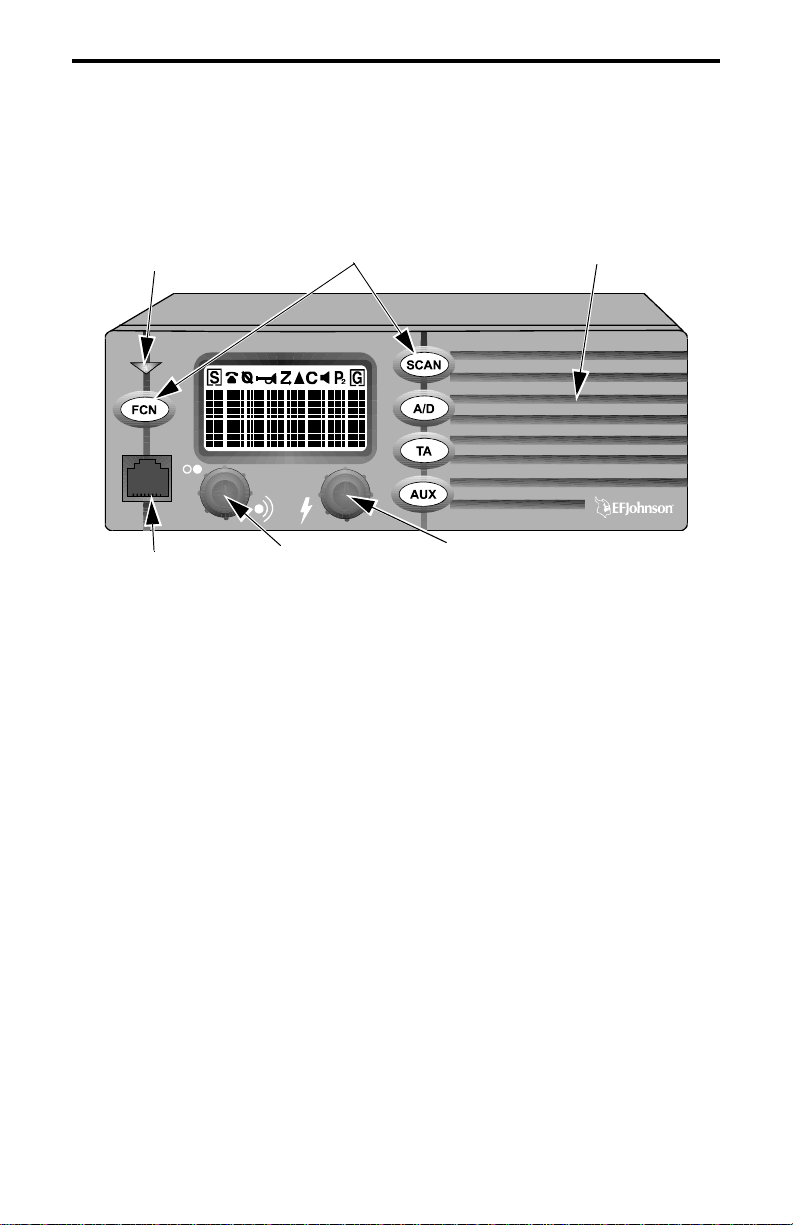
CONTROLS AND DISPLAY
Transmit/Busy
Indicator
Microphone
Jack
Option Switches
On-Off/Volume
Speaker
Select Switch
Front Panel Controls
On-Off Volume - Pressing this knob tu rns power on an d off. The vehicle
ignition switch may also control power as described in “Power Turn-Off
Delay” on page 27. Rotating this knob sets the speaker volume (see
page 15).
Select Switch - This switch changes the selected system or group and is
also used for other functions such as selecting parameters in the menu
mode. To change the system or group, press this knob to switch between
the system and group select modes, and then rotate it to increase or
decrease the system o r group. Refer to “Selecting the Sys te m and Group”
on page 17 for more information.
This switch also has two alternate functions that are selected by first
pressing the FCN switch. Refer to the FCN switch description which
follows for more information.
11
Page 12

CONTROLS AND DISPLAY
Option Switches - The five front panel option switches can be
programmed by your system operator for the functions which follow.
Refer to the section indicated for more information on a function. The
key cap usually indicates the function controlled by the switch.
A/D - Scan list add/delete (see page 35)
CG - Call Guard squelch disable (see page 46)
EMER - Emergency switch (see page 24)
ENCPT - Encryption on-off (see page 24)
FCN - Function select (see following description)
HORN - Horn alert on-off (see page 26)
MON - Monitor mode on-off (see page 39)
AUX - Option select (see page 27)
PRI - Priority sampling on-off (see page 46)
SCAN - Scan on-off (see page 33)
STLH (AUX) - Stealth mode select (see page 29)
TA - Talk-around on-off (see page 45)
(Blank) - Not used (disabled)
FCN (Function) Switch - This switch (if programmed) selects the
following functions:
Menu Mode Select
Home Sys/Grp Select
Conv Squelch Set
- Press FCN twice (see page 30)
- FCN/press Select switch (see page 26)
- FCN/rotate Select switch (see page 18)
Transmit/Busy Indicator - Indicates the following conditions:
Red
- Transmitter keyed, normal power output
Orange
- Transmitter keyed, power reduced because internal
temperature is high
Green
- Busy conventional group (channel). Refer to “Conventional
Operation” on page 38 for more information.
Microphone Jack - Connection point for the microphone.
Microphone Push-To-T alk (P TT) Switch (Not Shown) - Push-butt on on
the microphone which is pressed to key the transmitter.
12
Page 13
CONTROLS AND DISPLAY
Speaker - The internal speaker is located behind the grille. An optional
speaker can be connected t o the exter nal speake r jack locate d on the back.
See “Speaker Jack” description which follows.
Antenna
Jack
Power
Jack
Speaker
Jack
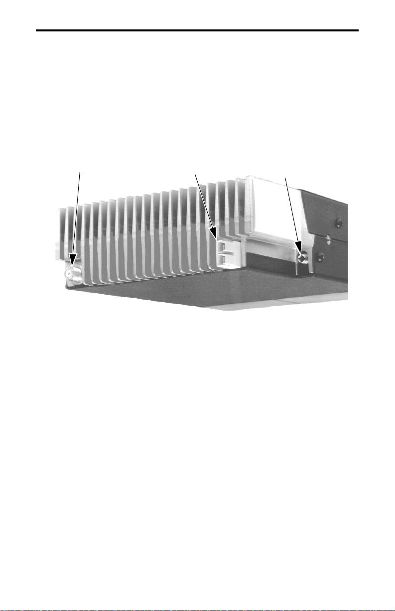
Rear Panel Jacks and Connectors
Antenna Jack - Miniature UHF jack for connecting the 50-ohm antenna.
Power Jack - Connection point for the power cable which at taches to the
vehicle battery. A nominal 12-volt DC, negative ground power source is
required.
Speaker Jack - Conne ction point for an opti onal external 4.7-ohm, 5-wat t
speaker. The internal speaker is automatically disabled when a speaker is
plugged into th is jack.
Accessory Cable (Not Shown) - This optional cable is used to connect
functions such as ignition switch sense and horn alert to the transceiver.
Data Cable (Not Shown) - This optional cable is used to connect data
equipment such as modems and data terminals to the transceiver.
13
Page 14
CONTROLS AND DISPLAY
System Scan
List
Encryption
Phone
ID
Horn
Alert
Scan
Selected
16-Character
Message Area
Call
Priority
Groups
Option
Group Scan
List
Monitor
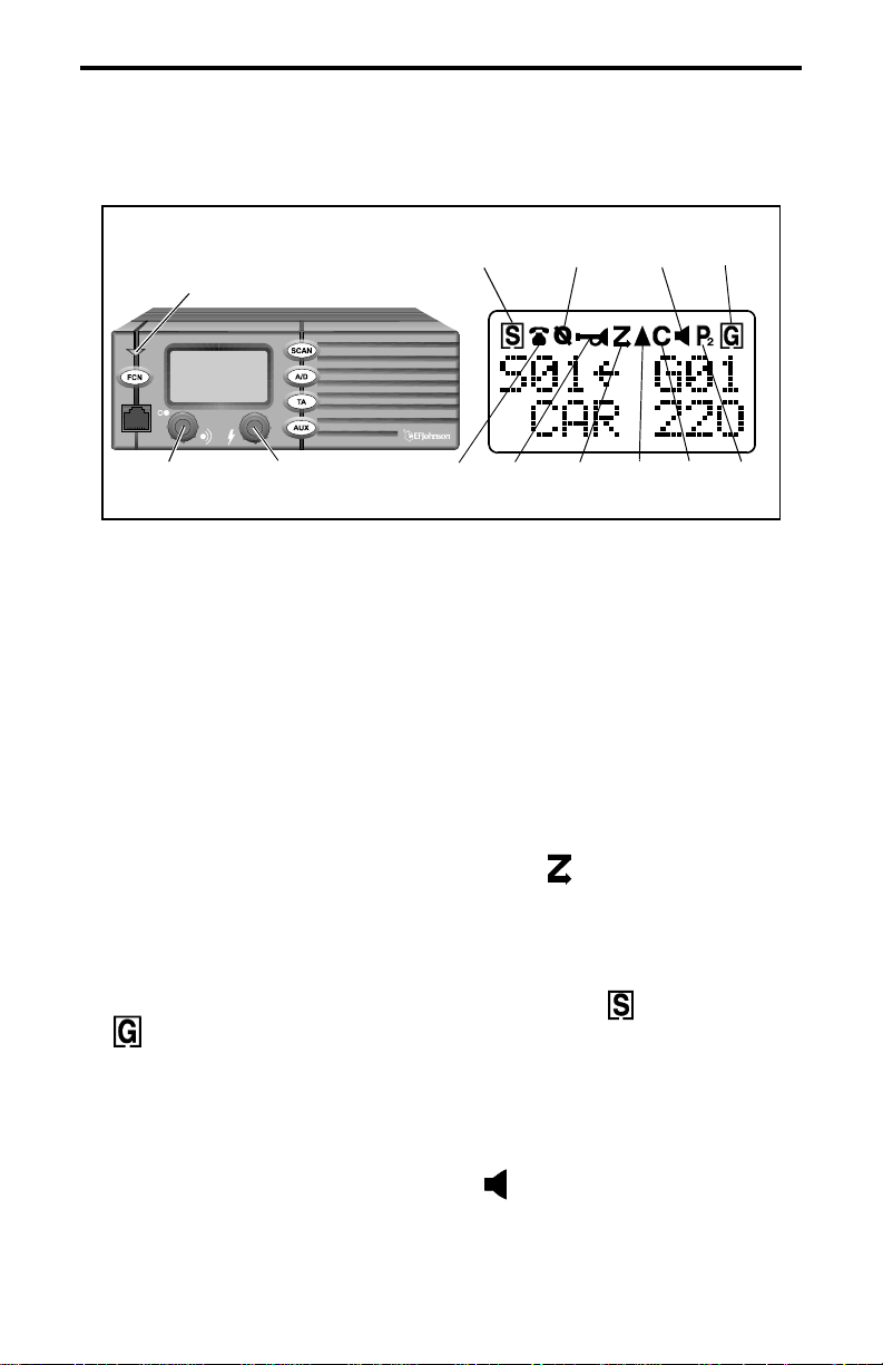
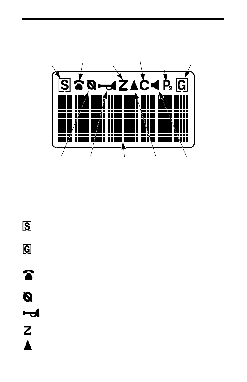
Display Description
16-Character Message Area - Indicates the selected system and group
(see page 16) and also error conditions and status information.
- Indicates that the displayed system is in the scan list and scanned
normally (see page 35).
- Indicates that the displayed group is in the scan list and scanned
normally (see page 35).
- Indicates that t he selected group is progra mmed f or telephone calls
(see “TELEPHONE CALLS” on page 21).
- Indicates that optional encryption is enabled (see page 24).
- Indicates that the horn alert is enabled (see page 26).
- Indicates that scanning is enabled (see page 33).
- Indicates that an option controlled by the AUX switch is enabled
(see page 24).
14
Page 15

GENERAL OPERATION
- Indicates that a ca ll has been received on a group programmed for a
call indicator (see page 24). To turn this indication off, press any key.
- Indicates that the m oni tor mode is enabled. This mode disables Call
Guard squelch and other squelch control features so that all messages are
heard on conventional systems (see page 44).
- When only is displayed, the selected or displayed group is
scanned as a first priority group. When is displayed, it is scanned as a
second priority group (see page 46).
GENERAL OPERATION
Power-Up Sequence
When power is turned on, the backlight turns on, all segments in the
display are momentarily enabled, and the last seven digits of the transceiver part number are very briefly displayed. A beep then sounds (if
tones are enabled) and the transceiver is ready to be used.
Determining Volume Level
The relative volume sett ing ca n be d etermi ned by notin g t he pos ition
of the index on the volume knob. You may also be able to enable a reference tone or background noise for use in setting the volume. Proceed as
follows:
• If key press tones are enabled, a short tone sounds when an option
switch is pressed or the Select switch is pressed or rotated.
• If a conventional sys tem is sel ected, ta ke the micro phone of f-hook a nd
if someone is using the channel, voice is heard. If no one is using the
channel, the squelch control can be adjusted counterclockwise as
described in “Setting Squelch Control” on page 18 and noise is heard.
It is not pos sible to unsquelc h the transceiver in this manner when an
LTR system is selected.
15
Page 16
GENERAL OPERATION
Backlight Operation
The display and keypad backlight can be controlled by the BACKLIGHT menu parameter (see page 38). The three states that can be
selected are Bright, Dim, and Off. If this menu parameter is not selectable, the backlight is fixed in one of these states by programming.
System/Group Display Information
The currently select ed s yst em and group are displayed using either a
Numeric or Alpha Tag display mode. The display mode is selectable if
the S/G DISPL menu parameter is available (see page 32). Otherwise, it
is fixed in one of these modes by progr amming. These modes function as
follows:
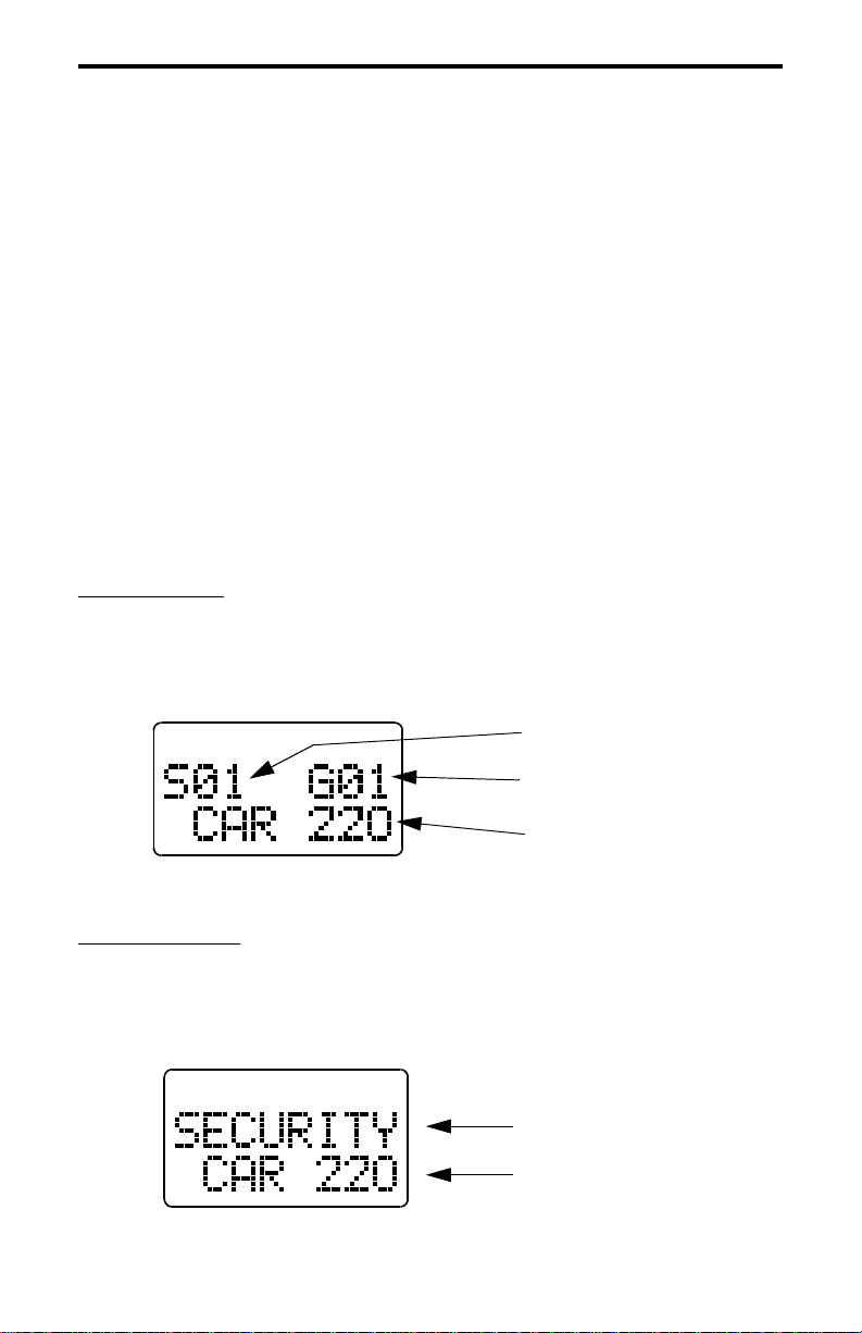
Numeric Mode
- In the numeric mode, the selected system and group
numbers are displayed on the top line as Sxx and Gxx, and the group
alpha tag is displayed on the bottom line. For example, System 1, Group
2 (CAR 220) is displayed as follows. The system alpha tag is not
displayed in this mode.
System Nu mber
Group Number
Group Alpha Tag
Numeric Display Mode
Alpha Tag Mode
- In the alpha tag mode, the system alpha tag is
displayed on the top line and the group alpha tag is displayed on the
bottom line. For example, a “SECURI TY” sys te m and “CAR 220 ” gr oup
are displayed as follows. The system and group numbers are not
displayed in this mode.
System Alpha Tag
Group Alpha Tag
16
Alpha Tag Display Mode
Page 17
GENERAL OPERATION
Selecting the System and Group
The front panel Select switch is used to change the system and
group. Pressing this switch toggles between the system and group select
modes, and then rotating it increases or decreases the system or group.
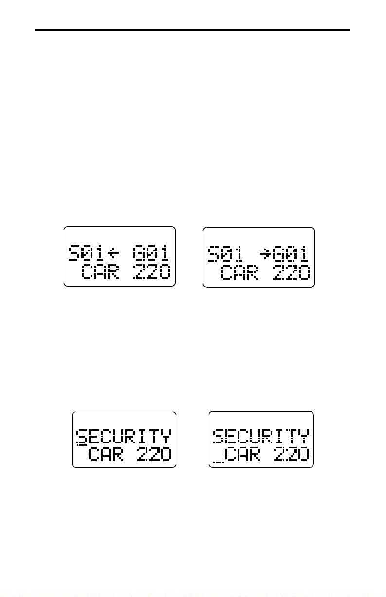
In the Numeric display mode (se e prec eding de scri ption) , the s ystem
select mode is indicated when the arrow points to “Sxx”, and the group
select mode is indicated when it points to “Gxx” (see following diagram).
System Select
Mode
Group Select
Mode
Select Mode Indication With Numeric Display
In the Alpha Tag display mode, the system select mode is indicated
by an underline in the left-most character position of the system alpha
tag. Likewise, the group select mode is indicated by an underline in the
left-most position of the group alpha tag (see following diagram).
System Select
Mode
Group Select
Mode
Select Mode Indication With Alpha Tag Display
The transceiver can be programmed so that after a change is made,
the current select mode remains enabled or a default mode is selected
after a delay of up to 15 seconds. This programming also controls the
mode that is selected when power is turned on.
17
Page 18

GENERAL OPERATION
Setting Squelch Contro l
NOTE: This procedure sets the squelch level used for conventional calls
only. The squelch level for LTR calls is preset and not affected by this
adjustment. For more information on the various operating modes, refer
to page 38.
If conventional systems are programmed, the squelch level can be
set if the FCN option switch is enabled. Proceed as follows:
1. Select a conventiona l system and then a group that is no t busy . Take the
microphone off-hook to enable monitoring.
2. Press the FCN switch and then rotate the Sele ct swi tc h a s you woul d a
normal squelch control . Rotate it count erclockwise until receiver noise
is heard and then clockwise slightly past the point where the noise
mutes. The squelch adjust mode is indicated by “SQUELCH” on the
upper line of the display, and the relative squelch level is indicated by
a bar graph on the bottom line.
3. To select the current level and exit this mode, press the Select switch.
This also occurs automatically 2 seconds after no change is made or 8
seconds after no activity.
4. If both narrow and wide band channels are used, perform this adjust-
ment on both types because separate settings are maintained.
NOTE: Some readjustment may be required if weak messages are not
heard or unsquelching occurs when no messages are present.
18
Page 19

STANDARD CALLS
STANDARD CALLS
Introduction
Most calls you make are probably the standa rd ty pe descr ibed in this
section. These calls are between you and another mobile or control
station. The main difference between these calls and the other type that
can be placed (telephone calls) is that no number is dialed using a
keypad. The following procedure applies to both LTR and conventional
operation.
Placing a Standard Call
1. Turn tran sce ive r powe r on and se t the volume as described starting on
page 15. With convention al operation, als o set the squelch as described
on page 18.
2. Select the syst em a nd g rou p of the mobile being called as described in
“Selecting the System and Group” on page 17.
3. If a conventional call is being placed, moni tor the cha nnel manua lly or
automatically as described on page 39.
4. Press (and hold) the mi crophone PTT (push-to-talk) switch to talk and
release it to listen. Ope ration wit h LTR and conventional systems is as
follows:
LTR Operation
• If the proceed tone is enabled (see page 28), it sounds shortly after
the PTT switch is pressed to indicate that the radio system was
successfully accessed. If the proceed tone is not enabled, no tone
sounds when the system is successfully accessed. The proceed and
other tones ca n be disabled as describ ed in “Tone Select” on page 30.
• If the radio system is busy, the busy tone sounds (see page 47) and
“BUSY” is indicated on t he lower line of the dis play . If you cont inue
pressing the PTT switch, the system is accessed when it becomes
available.
19
Page 20

STANDARD CALLS
• If an out-of-range condition exists, the intercept tone sounds (see
page 47) and “OUT-RNGE” is indicated on the lower line of the
display. No more access attempts are made once this indication
appears. Release the PTT switch and drive closer to the radio system
or away from shielding structures and try again.
Conventional Operati on
• If the channel is busy and the Transmit Disable On Busy feature is
programmed, “DSBL BSY” is indicated on the lower line of the
display, the busy tone sounds, and the transmitter is disabled (see
page 44).
• Otherwise, busy and out-of-range conditions are not indicated and
speaking can begi n when the PTT switch is pressed after monitorin g
the channel. If th e p roceed tone is ena bled o n c onventi onal syste ms,
it indicates when speaking can begin but does not indicate that the
radio system has been successfully accessed.
5. When the call is complete, place the microphone back on-hook.
Receiving a Standard Call
1. Turn tran sce ive r powe r on and se t the volume as described starting on
page 15. With convention al operation, als o set the squelch as described
on page 18.
2. Select or scan th e syst em and gr oup prog rammed for the c all yo u want
to receive (see page33 for scan information).
3. When the message is received, the display usually changes to the
system and group of the call. Take the microphone off-hook and press
the PTT switch to talk and release it to listen. If scanning, a response
may not automatically occur on the group of the call (see page 36).
20
Page 21

TELEPHONE CALLS
TELEPHONE CALLS
Placing Telephone Calls
NOTE: Telephone calls can be placed and received only if that service is
available to you and your transceiver has been programmed appropriately. A microphone equipped with a telephone keypad is required to dial
the telephone number.
The telephone calling feature allows you to place and receive telephone calls using your transceiver. The following information describes
how these calls are made with LTR operation. If you can make telephone
calls with conventional operation, the procedure may be somewhat
different and your system operator will then provide additional information. Proceed as follows:
1. Turn tran sce ive r powe r on and se t th e volu me as des cribed starting on
page 15.
2. Select the system and group programmed for telephone calls. When a
telephone group is selected, is displayed.
3. T o obtain the dial ton e, briefly press the P TT switch. If the proceed tone
is used, press the PTT switch until a beep sounds. If a dial tone is then
heard, proceed to step 4.
Busy and Out-Of-Range Conditions
Busy and out-of-range conditions are indicated the same as with LTR
standard calls des cr ibe d o n pa ge 19. The followi ng a ddi ti ona l fea tu res
may be available with telephone calls:
Busy - If Busy Queuing is programmed (see page 42), the call is automatically placed in a queue when the PTT switch is released. The
Busy Queuing mode is indicated by “IN QUEUE” in the display.
21
Page 22

TELEPHONE CALLS
Out-of-Range - If the System Search feature is selected (see page 42),
that feature is a utomatically selected when the PTT switch is released.
The System Search mode is indicated by “SYS SRCH” in the display.
4. With t he dia l tone sounding, dial the number u si ng t he 0- 9 ke ys on the
microphone keypad. If the mi crophone has a memory, you may also be
able to recall the number fr om memory. The P TT switch does not need
to be pressed while you are dialing if the transmitter automatically
keys. If too much time elapses between digits, the call is terminated.
5. After the number is dialed, release the PTT switch (if it was pressed).
Landside ringing (or a landside busy condition) should then be heard.
6. When the other party answers, press the PTT switch and respond. The
PTT switch must be pressed to talk and released to listen (the same as
with mobile-to-mobile calls).
7. When the call is finished, it shoul d be ter minated . This is us ually done
by pressing the # key, and termination is indicated by three beeps.
Termin ating the call in thi s manner prevents extra billing that may
occur while the system automatically detects the end of the call.
Receiving a Telephone Call
1. Turn tran sce ive r powe r on and se t the volume as described starting on
page 15.
2. Select or scan the system and group programmed for telephone calls.
When a telephone group is selected, is displayed.
3. When “ringing” is heard, press the PTT switch and respond. The PTT
switch must be pressed to talk and released to listen the same as with
standard calls.
4. When the call is finished, it should be terminated as in step 7 of the
preceding section.
22
Page 23

GENERAL FEATURES
Landside-Originate Calls
Calls can be placed from a landside telephone to your transceiver if
the radio system and transceiver have that capability. With most systems,
a mobile can be called directly (each has a unique telephone number).
With others, a mobile may be called as follows:
1. Dial the number of the radio system in which the mobile is operating.
2. When the system answers, a short tone sounds to indicate that the
number of the mobile should be dialed. This number is usually five
digits long and is supplied by your system op erator . The first t wo digits
are the home repeater number and the other digits are the group ID of
the mobile being called . This numbe r must be di aled u sing a t one-ty pe
telephone. If too much time elapse s before dialing is star ted or between
dialed digits, the call is terminated.
3. Ringing is then heard by the landside caller while the mobile is being
rung.
GENERAL FEATURES
Bank Select
A bank is a collect ion of selectable systems that ha ve been set up for
a specific application. For example, one bank could be programmed for
operation in Minneapolis and another for operation in Milwaukee. Each
bank is identified by a unique alpha tag, and up to sixteen banks can be
programmed.
Banks are selected by the BANK SEL menu parameter (see
page 32). Rotate the Select switch to display “BANK SEL” on the top
line and the current bank is then displayed on the bottom line. Press the
Select switch to change the bank. If this menu parameter is not available,
banks are not selectable.
23
Page 24

GENERAL FEATURES
Call Indicator
The call indicator is “ C” in the uppe r par t of th e dis pla y as shown in
the following illustration. The purpose of this indication is to show that a
call was received while you were away from the vehicle. Individual
groups can be programmed for this feature and it then turns on when a
call is received on one of those groups.
Call
Indicator
This indicator is turned off by pressing any button or turning transceiver power off and then on. If scanning and the “last received” configuration is programmed (see “Transmitting In The Scan Mode” on
page 36), the system and group of the last call are displayed. Otherwise,
the currently selected system/group is displayed.
Emergency Switch
If the EMER option switch is programmed (see page 30), it is used
to set up a high priority call. When this switch is pressed,
“EMERGNCY” is displayed on the lower line (unless this message has
been disabled by programming) and a preprogrammed emergency
system/group is selected. However, no call is automatically placed. This
access mode minimizes, as much as possible, the chance that the system
will be busy when the call is placed by pressing the PTT switch. If you
have an EMER switch, consult your system operator for more information on how to use it.
Encryption
Voice encryption is an optional feature that prevents conversations
from being monitored by casual eavesdropping and analog scanners. It
does this by encrypting your voice so that it can be understood only by
someone using a transceiver equipped with similar encryption device.
24
Page 25

GENERAL FEATURES
Each group can be programmed so that when it is selected, encryption is automatically enabled. Wh en encryption is ena bled, is indicated in the display as shown below.
Encryption
Indicator
If you have the ENCRYPT menu parameter or ENCPT option
switch, the encryption group programming can be temporarily overridden. Selecting another system or group causes encryption to revert to
the status programmed for that group.
Encrypted calls are received even if encryption is not enabled.
However, encryption must be enabled to transmit an encrypted call.
When transmitting an encrypte d call, wait approxi mately 1 seco nd before
speaking. This gives the receiving encryption device time to establish
synchronization which ensures that all of the first word is received. If the
proceed tone is used (see page 28), speaking can begin as soon as it
sounds because it is delayed for the required time.
Function (FCN) Switch
If an option switch is programmed for FCN (function), it performs
the following fu nct io ns. If this switch is not programmed, these functions
are not available. When the function select mode is active, “FCN” is
displayed on the lower lin e of t he di spl ay. The function mode is automatically exited after 8 seconds of no activity.
Menu Mode Select
- Pressing FCN twice selects the menu mode as
described on page 32.
Home System/Group Select
- Pressing FCN and then the Select switch
selects the home system/group as described in the next section.
25
Page 26

GENERAL FEATURES
Squelch Adjust - Pressing FCN and then rotating the Select switch with a
conventional system selected sets the squelch level as described on
page 18.
Home System/Group Select
To select the preprogrammed Home system/group, simply press the
FCN switch and then the Select switch. The Home system/group is then
displayed and it becomes the selected system/group. If no home group
has been programmed, the last selected group of the home system is
selected. If you do not have a FCN switch, or if no Home system is
programmed, this feature is not available.
Horn Alert
If this feature has been installed by your sy st em op erator, it activat es
an external alert such as the vehicle horn or lights when a call is received
on a group programmed for horn alert. When the horn alert is enabled,
is displayed as shown in the following illustration.
Horn Alert
Enabled
When enabled, the horn alert pulses on and off for 1-8 cycles and
then goes back to the dis abled state. To change the currently selected horn
alert mode, the HORN option switch or HRN ALRT menu parameter can
be used if available (see page 30).
The horn alert is programmed to operate in the manual or automatic
mode (see descriptions which follow). If the ignition switch does not
control transceiver power, only the front panel power switch affects oper-
ation when applicable. Refer to “Power Turn-Off Delay” on page 27 for
more information.
26
Page 27

GENERAL FEATURES
Manual Off/On Mode
The horn alert mode does not change when power is turned on and
off by either the igni tion switch or power switch. Therefore, the hor n alert
is entirely controlled by either the HORN option switch or menu
parameter.
Auto Off/On Mode
Ignition Switch - The horn alert always tu rns of f whe n the ign ition switch
is turned on, and always turns on when the ignition switch is turned off (if
there is a turn-off delay).
Power Switch
- The horn alert always reverts to the off condition when
power is turned on by the power switch.
NOTE: The preceding automatic operation overrides any mode that may
have been selected by the HORN option switch or HRN ALRT menu
parameter.
Option Select
The AUX option switch or OPTION menu parameter can be used to
control an accessory that may have been installed by your system operator. If the switch is used, the enabled condition is indicated by in the
display.
Power Turn-Off Delay
Your transceiver may hav e bee n ins ta ll ed so t hat the vehi cle igni ti on
switch as well as the front-panel power switch control transceiver power.
If this is the case, both the ignition switch and the front panel power
switch must be on for transceiver power to turn on.
When the igni tion switch controls power, turn-off delays of Immediate, 10, 20, 30, 40, or 50 minutes, 1, 2, 4, 8, 10, 12, or 16 hours or
Forever can be programmed. The delay can be overridden at any time by
turning power off using the front-panel power switch or turning the ignition switch back on.
27
Page 28

GENERAL FEATURES
A power turn-off dela y allows fea tures such as the horn alert a nd call
indicator to remain active for a time after the ignition switch is turned off.
At the same time, advantages of ignition switch control are utilized such
as preventing battery discharge that may occur if the transceiver is accidentally left on for an extended period (see page 54).
Proceed (Clear-To-Talk) Tone
This is a short tone that sounds shortly after the PTT switch is
pressed to indicate that the radio system has been accessed and speaking
can begin. This tone can be programmed so that it sounds on LTR
systems but not conventional systems. In addition, this and other tones
can be disabled on all syste ms by the TONES menu parameter (see “Tone
Select” on page 30) or system operat or progra mming. Eit her a sta ndard or
loud (two-pitch) tone can be programmed.
On LTR systems, if the radio system is busy when making a call , th e
busy tone sounds instead of the pr oceed t one and “ BUSY” is ind icate d on
the bottom line of the display. If the PTT switch is held down, the system
is accessed and the proceed tone sounds when it is no longer busy. If an
out-of-range condition occurs, the intercept tone sounds and “OUTRNGE” is indicated in the display. The PTT switch must be released to
make another call attempt. Refer to pa ge 47 for more information on the
busy and intercept tones.
On conventional systems, the Transmit Disable On Busy fe at ure can
be used to automatically perform monitoring (see page 44). The proceed
tone then does not sound if the channel is busy. Otherwise, the proceed
tone (if enabled) sounds on conventional systems even if the channel is
busy.
With all operating modes, if encryption is used, a 0.9-second delay
occurs before this tone sounds and two beeps are heard instead of one. A
short delay may also occur with conventional calls. These delays ensure
that the radio path is complete before you begin talking so that part of
your first word is not lost.
28
Page 29

GENERAL FEATURES
Receive-Only Groups
Any group can be programmed for monitoring only (transmitting is
disabled). If the PTT switch is pressed with one of these groups selected,
the intercept tone sounds and “TX DSBL” is displayed.
Stealth Mode
The stealth mode disables the following tones and indicators so that
they do not reveal that you are transmitting or otherwise indicate your
presence. The speaker audio and display remain enabled in this mode.
• All tones (see “Tone Select” on page 30)
• The front panel transmit/busy indicator (see page 16)
• Display backlight
The stealth mode can be selected by an option switch or the
STEALTH menu parameter (see page 32), or is fixed in the on or off
mode by programming. There is no special indication that this mode is
selected except “On” is displayed under “STEALTH” in the menu mode.
Time-Out Timer
The time-out timer disables the transmitter if it is keyed continuously for longer than the progr ammed time. It can be progra mmed for 0.5
- 5.0 minutes or disabled entirely. If the transmitter is keyed continu ousl y
for longer tha n the programmed time, the transmitter i s disabled,
“TIMEOUT” is indicated on the lo wer line of the display, and the in tercept tone sounds. The timer and tone are reset by releasing the PTT
switch. Ten seconds before time -out occur s, a beep so unds to indi cate tha t
time-out is approaching. There is also a timer that can be programmed to
prevent transmitting for up to one minute after time-out occurs.
One use of the time-out timer feature is to prevent a repeater from
being kept busy for an extended period by an accidentally keyed transmitter. It can also prevent possible damage to the transmitter caused by
transmitting for an excessively long period.
29
Page 30

OPTION SWITCHES AND MENU MODE
Tone Select
If the TONES menu parameter is selectable, the tones that sound can
be selected. Otherwise, the tones that sound are fixed by programming.
The following choices are available. Refer to page 32 for more information on using the menu mode.
Silent - All tones are disabled.
Key Beep - Only the Select switch and key press tones are enabled.
Alert - All tones except the preceding Key Beep tones are enabled.
All Tones - Both the Key Beep and Alert tones are enabled.
Transmitter Thermal Foldback
If the transmit ter temp eratu re in creas es to th e po int where d amage to
the transceiv er could result, power is automaticall y cut back. When this
happens, the transmit indicator on the front panel is orange instead of red
when the transmitter is keyed. After sufficient cooling occurs, power
output returns to the normal level and the indicator changes back to red.
One time when this indication could occur is if you transmit for an
extended period.
OPTION SWITCHES AND MENU
MODE
Option Switches
All five option switches on the front panel are programmable by
your system operator. The available option switch and menu mode functions are shown in the table on page 31. Those which can be assigned to
an option switch are indicated by an entry in the “Option Switch”
column. Refer to the page listed in this table for a description of the function. If a function is controlled by an option switch, it cannot be
controlled by the menu mode and vice versa. Some switches may not be
used.
30
Page 31

OPTION SWITCHES AND MENU MODE
Menu Mode and Option Switch Functions
Function Menu Items
Option
Switch
See Descrip.
on Page
Add/delete (scan list prg) --- A/D 35
Backlight adjust BACKLGHT --- 16
Bank select BANK SEL --- 23
Call Guard Sq. disable --- CG 46
Emergency --- EMER 24
Encryption on-off ENCRYPT ENCPT 24
Function select --- FCN 25
Home sys/grp select --- FCN then
26
press Sel Sw
Horn Alert on-off HRN ALRT HORN 26
LTR system search SYS SRCH --- 42
Menu mode select --- FCN (twice) 32
Monitor m ode select --- MON 44
Option select OPTION AUX 27
Priority sampling on-off PRIORITY PRI 46
Scan on-off --- SCAN 33
Scan type select SCN TYPE --- 33
Scan continue on-off SCN CONT --- 36
Scan list save mode SCN SAVE --- 35
Stealth mode select STEALTH STLH 29
Squelch adjust --- FCN then
18
rotate Sel Sw
System/group display
S/G DISPL --- 16
mode
T al k-ar ound on- off TALKARND TA 45
Tone type select TONES --- 30
NOTE: Parameters left blank are not available.
31
Page 32

OPTION SWITCHES AND MENU MODE
Menu Mode Introduction
The menu mode is selected by pre ssing the FCN swit ch twice . If thi s
switch is not programmed, the menu mode is not available. Functions
which can be controlled by the menu mode are indicated by an entry in
the “Menu Items” co lumn of the t able o n page 31. Refer to t he pag e lis ted
in the table for a description of the function. Some functions may not be
used, may be in a fixed state, or may be controlled by an option switch.
The menu parameter that controls that function is then not displayed.
Using Menu Mode
To use the menu mode, proceed as follows:
1. To select the menu mode, press the FCN switch twice. The menu
display follows. The top line indicates the function being edited, and
the bottom line indicates the current status of that function.
Function
Status
2. T o display the va rious functions t hat are controllabl e by the menu mode
(top line indication), rotate the Select switch. The currently selected
status of that function is displayed on the bottom line.
3. To change the selected status, press the Select switch. The selections
displayed for each menu function are shown on page 52.
4. To display another menu function, rotate the Select switch. Then
change the status if desired as described in the preceding step.
5. The selected statu s condition s for the v arious functi ons are save d when
the menu mode is exited in one of the following ways:
32
Page 33

SYSTEM AND GROUP SCAN
• Pressing the FCN switch again
• Pressing the PTT switch
• Automatically when time-out occurs 2 seconds after a change is
made or 8 seconds after no changes are made.
NOTE: Calls cannot be received or transmitted while the menu mode is
selected.
SYSTEM AND GROUP SCAN
Introduction
The scan feature monitors, in sequence, the programmed systems
and/or groups in the scan list. When a message is detected that the transceiver is programmed to receive, scanning stops and the message is
received. Shortly afte r the message is complete, sc anning resume s (unless
it has been disabled).
System Scanning
in the system scan list. When system scanning is not used, calls are
detected on only the currently selected system.
Group Scanning
the current or scanned systems that are in the group scan list. When group
scanning is not used, calls are detected on only the currently selected
group or if system scanning, on the last selected group of each system.
System and/or group scanning are turned on and off by the SCAN
option switch. When system and/or group scanning is enabled by this
switch, is indicated in the display (see following illustration). Then
when system or group scanning is actually occurring, a scrolling underline is displayed und er each c haract er in the uppe r line of th e displa y. The
microphone must be on-hook for scanning to occur (unless off-hook
detection has been disabled by programming).
- System scanning detects calls on all systems that are
- Group scanning detec ts ca lls o n all selec table groups in
33
Page 34

SYSTEM AND GROUP SCAN
System Scan List Group Scan List
System or Group
Scanning Selected
System or Group
Scanning Occurring
The type of scanning selected is determined by the menu mode SCN
TYPE parameter (see page 32). If that parameter is not selectable, the
type of scanning is fix ed by programming. The a vailable scan ty pes are as
follows.
SYS-GRP - Both system and group
GRP ONLY - Group scanning only
OFF - Both types disabled (SCAN switch non-functional)
If the SCAN option switch is not programmed, the selected mode is
always enabled. If the switch is enabled but the menu SCN TYPE parameter is not selectable, the scan type is fixed by programming.
Group scanning can be selectively disabled on systems by programming. It then does not occur on those systems even if enabled as just
described. The select ed system and group can be changed while sca nni ng
using the Select switch in the normal manner. Scanning resumes shortly
after the ch ange is made.
When a call is received in the scan mode, the display changes to the
system and group of the call. Programming determines if this change is
temporary (until scanning resumes) or permanent, and if a response
occurs on the system/gro up of the cal l or the se lected sy stem/group . Refer
to “Transmitting In The Scan Mode” on page 36 for more information.
34
Page 35

SYSTEM AND GROUP SCAN
Scan List Programming
General
NOTE: The selected (displayed) system and group are always scanned,
even if they are deleted from the scan list.
The system and group scan lists are programmed using the A/D
(add/delete) option switch. Pressing this switch changes the status of the
displayed system or group. The displayed system is in the scan list and
scanned normally when is displayed. Likewise, the di splaye d group is
in the scan list and scanned normally when is displayed (see
preceding il lustration).
The system/group select mode described on page 17 also controls if
the system or group scan list is changed when the A/D switch is pressed.
For example, to change the scan list status of the displayed system, press
the Select switch if necessary so that the system select mode is indicated
and then press the A/D switch.
Deleting a system only temporarily deletes the groups associated
with that system. When a system is added back into the scan list, the original group scan list is again active. Systems and groups can be deleted
from the scan list while listening to a message on the system or group by
pressing the A/D switch in the normal manner. Scanning resumes shortly
after the sy stem or group is deleted.
Scan list programming is not available if the A/D switch is disabled.
In addition, the gr oup scan list is not programmable if the group scanning
is disabled on the current system. If an attempt is made to program the
group scan list on one of these systems, a beep sounds, “GSCN DIS” is
flashed in the display, and no change occurs in the scan list.
Saving Scan List
If the menu mode SCN SAVE parameter is available, you can select
if scan list changes are saved. If “On” is selected, changes are saved as
they are made and the scan list is the same when power is turned on. If
35
Page 36

SYSTEM AND GROUP SCAN
“Off” is selected, they are no longer saved. Therefore, to store a list,
select “On”, program the list, then select “Off”. Then when power is
turned on, the scan list returns to the state that existed when “Off” was
selected.
If the menu SCN SAVE parameter is not selecta ble, the sc an list sa ve
mode is fixed by programming. If “On” is programmed, all changes are
saved and no change occurs in the scan lists when power is cycled. If
“Off” is programmed, they are not saved and the scan list reverts to the
default status when power is cycled.
Scan Delay and Continue Timers
When a message is received or tran smitte d while s canning , there is a
short delay before scanning resumes. The delay after receiving a call
prevents another message from being received before a response can be
made. Likewise, the delay after transmitting a ca ll en sures that you hear a
response to your call instead of another message occurring on some o the r
system or group. Note that scanning does not resume if it has been
disabled, such as by taking the microphone off-hook.
There is also a scan continue timer that may be programmed. This
timer controls the maximum time that a call is received before scanning
resumes. Times up to 60 seconds can be programmed. This prevents
scanning from being delayed for long periods by lengthy calls. If the
menu SCN CONT parameter is selectable (see page 32), this feature can
be turned on and off.
Transmitting In The Scan Mode
General
When a message is received in the scan mode, programming determines if the selected system/group does not change or changes permanently or temporarily to that of the call. This then affects the system/
group on which a response to the message occurs and also the system/
group that is selected when the scan mode is exited by pressing the
SCAN switch. The three programmable configurations are as follows:
36
Page 37

SYSTEM AND GROUP SCAN
Last Selected - The selected system/group does not change when calls
are received on other system/groups. Therefore, to respond to a message
not on the selected system/group, one of the following methods must be
used. With this configuration, the display may not indicate the system/
group on which the response occurs.
• Select the system/group of the call manually using the Select switch.
• Before scanning resumes, exit the scan mode by pressing the SCAN
switch. The system/ group of th e call then become s the sel ected sy stem/
group and it is not necessary to change it manually.
Last Received - The selected system/group changes to the system/group
of a call. Therefore, you can always respond to a call without having to
manually change the system/group. To return to the previously selected
system/group, manually select it using the Select switch.
Temporary Last Received - The system/group changes to the system/
group of a call for only the duration of the scan delay period (see
page 36.) Then when the delay expires and scanning resumes (if it is not
disabled), the selected system/group is again displayed. Therefore, you
can respond to a call without changing the selected system/group as long
as you do so before scanning resumes.
Fixed System/Group Transmit in Scan
Each bank can be programmed so that transmissions made in the
scan mode while scanning is occurring are on a preprogrammed system/
group. Note that scanning must be occurring (scrolling underline
displayed) when the transmitter is keyed. Since taking the microphone
off-hook normally disables scanning (unless off-hook detection is
disabled), the transmitter usually must be keyed with the microphone onhook.
If a transmission occurs under these conditions, the selected system/
group also changes. If the transmitter is keyed with scanning halted, the
programming described in the preceding section takes precedence.
37
Page 38

LTR AND CONVENTIONAL MODES
LTR AND CONVENTIONAL MODES
General
Each selectable syst em ca n be programmed for LTR or conventional
operation by your system oper ator. The type or types of operation that are
programmed in your transceiver are determined by the type of radio
equipment being used in your radio system. The differences in operation
are described in the following information and elsewhere in this manual
as required.
LTR Operation
The LTR mode provides automatic channel selection (trunking) and
monitoring before transmitting. In addition, special tones and display
messages indicate busy and out-of-range conditions. Selecting a system
selects a collection of grou ps and other information such as fixed priority
receive ID codes. Sele ctin g a group sele cts a tran smit and rec eive ID co de
and other information which controls the mobile or mobiles being called
and what calls are received. LTR features are described starting on
page 40.
Conventional Operati on
In the conventional mode, selecting a system selects a collection of
channels and other information unique to those channels. Selecting a
group selects the specific channel and also squelch coding (if any) used
on that channel. Conventional features are described starting on page 44.
There are no tones or messages to indicate busy or out-of-range
conditions in this mode. A busy channel (group) is detected manually or
automatically as described in the following information. An out-of-range
condition cannot be detected automatically but may exist if you cannot
get a response to any of your messages . Refer to “Ope rat i on At Exte nded
Range” on page 54 for more information.
38
Page 39

LTR AND CONVENTIONAL MODES
To properly receive calls in the conventional mode, the squelch
control must be set as described in page 18. If this control is not set properly, weak messages could be missed or noise could be heard when no
message is present. In the LTR m ode, the squelch level is fixed and
setting this control has no affect.
Monitoring Conventional Channels Before Transmitting
Regulations require that the channel be monitored before transmitting to make sure t h at i t i s not be ing used by someone else. If you we re t o
transmit when someone else is talking, you would probably disrupt their
conversation. As previously stated, monitoring is performed automatically in the LTR mode. In the conventional mode, it must be performed
automatically or manually as follows.
Automatic Chann el Monitoring
If the selected group is programmed for the Transmit Disable On
Busy feature, monitor ing is perf ormed automat ically. Refer to page 44 for
more information on this feature.
Manual Channel Monitoring
If the Transmit Disable On Busy feature is not used, monitoring
must be performed manually as follows:
Busy Indicator - With scanning disabled and the squelch control
adjusted as described on page 18, note if the indicator on the front panel
is green. If it is, a signal has been detected on the selected system
(channel) and you should not transmit a message until it turns off.
Monitor Mode - There may be times when the busy ind icati on is on eve n
though no one is using the channel . Monit oring should the n be perfo rmed
using the monitor mode. This mode is enabled by taking the microphone
off-hook (unless off-hook detection has been disabled by programming).
The monitor mode temporarily disables Call Guard squelch (see description on page 46) and scanning so that all messages on the channel are
heard. The monitor mode i s indicated b y in the display as shown i n the
39
Page 40

LTR FEA TURES
following illustration. The monitor mode can also be enabled by the MON
or CG option switch if it is programmed. Refer to the monitor mode
description on page 44 for more information.
Monitor Mode
Selected
LTR FEATURES
Standard and Telephone Calls
Standard calls are between two mobiles or between a mobile and a
control station. Telephone calls allow you to place and receive calls over
the public telephone system using your transceiver. Standard calls are
described starting on page 19, and telephone calls are described starting
on page 21.
Calls on Priority and Block ID Codes
Two fixed priority and a block of receive ID codes can be
programmed. These codes are in addition to the receive and transmit ID
code selected by the group sele ct function. Calls on the fixed priority and
block ID codes are received regardless of which group is selected or
group scanning. All that is required is that the system programmed with
those codes be selected or scanned.
Calls on the fixed priority ID codes have a higher priority than calls
being received on other ID codes. If a call with a higher priority is
detected while receiving a call, the current call is immediately dropped
and the higher priority call received. Telephone calls are not interrupted
by priority calls.
40
Page 41

LTR F EA TURES
If a call is received on one of the fixed priority ID codes, either
“PRIORTY1” or “PRIORTY2” is displayed on the bottom line. The
selectable groups are then che cked to s ee if an y have the same ID code. If
a match is found, the transceiver changes to that group. If no match is
found, the group does not change and a response cannot be made on that
ID code. The “Transmitting in the Scan Mode” programming described
on page 36 determines if a change is temporary or permanent.
When block ID codes are used, calls are dete cted on entire blocks of
ID codes. When a call is received on a block ID code, “BLK CALL” is
displayed and the selected group does not change.
Transmit Inhibit
The Transmit Inhi bit feature prevents the transmitter from keying if
the mobile you ar e c all i ng i s busy with another call. When the transmitter
is disabled by this feature, the intercept tone sounds and “TX INHIB” is
displayed (see following illustration). To make another call attempt, the
PTT switch must be released and pressed again. However, you may want
to wait a few seconds b efore m akin g ano ther at temp t so th at the oth er cal l
can finish.
One use of this feature is to prevent the accidental interruption of a
call in progress. This could happen when the other party unkeys or if a
higher priority ID is transmitted. It may also be used to provide an indication that the mobile you are calling is busy with another call. A similar
Transmit Disable On Busy feature is available on conventional systems
(see page 44).
41
Page 42

LTR FEA TURES
Busy Queuing
The LTR busy queuing feature places a telephone call in a queue if
the radio system is busy when it is placed. Then when the system
becomes available, the call is automatically placed. Standard (mobile-tomobile) calls are not queued by this feature. If queuing is programmed
and a busy condition is encountered, the queue mode is entered automatically when the PTT switch is released. The queue mode is indicated by
“IN QUEUE” on the bottom line of the display (see following
illustration).
When the radio system becomes available, it is automatically
accessed. A beep then sounds and a dial tone is heard. The call can then
be placed if desired. The queue mode is exited before the call is placed if
any of the following occur (exit is indicated when “IN QUEUE” is no
longer displayed).
• The PTT switch is pressed
• Any call is received
• Any front panel option switch is pressed
• Power is turned off
Calls are received normally in the queue mode. However, receiving
any call causes the mo de t o be e xited as indicated above. Group scanning
remains enabled while in the queue mode, but system scanning is temporarily disabled. This feature is enabled on individual LTR systems by
dealer programming and is then available with all telephone calls on
those systems.
System Search
If an out-of-range condition exists when attempting an LTR telephone call, the system search feature can be used to automatically search
42
Page 43

LTR F EA TURES
for a system within range. If enabled, the system search mode is automatically entered when the PTT switch is re lease d. This mode is in dic ated by
a short tone and “SYS SRCH” on the bottom line of the display as shown
in the following illustration.
The transceiver then attempt s to acces s, in succes sion, othe r syste ms
that have a group programmed for telephone calls. As each system is
accessed, a beep sounds. If a system is successfully accessed, the new
system/group is selected and a dial tone sounds. The telephone call must
then be placed within a few seconds or normal operation resumes. If no
system could be accessed, the intercept tone sounds, “NO PHONE” is
displayed, the system/group does not change, and the feature deactivates.
This mode can also be canceled at any time by pressing any front
panel option switch. If the menu mode SYS SRCH parameter is selectable (see page 30), this feature can be turned on and off. Otherwise, it is
either enabled or disabled on all LTR systems by programming.
Transpond
The transpond feature indicates if the mobile being called is in
service. To be available, it must be prog rammed i n the t ransc eiver you a re
calling. Each sele ctabl e LTR group can be programmed for thi s featur e. If
a call is received on one of these groups, the transceiver automatically
transmits a response. This causes the transceiver placing the call to
briefly unsquelch and the call indicator to turn on (if it is programmed on
the selected group).
43
Page 44

CONVENTIONAL FEATURES
CONVENTIONAL FEATURES
Monitor Mode
The monitor mode is used to monitor a channel before transmitting.
When this mode is selected, it tempor arily dis ables Cal l Guard squ elch or
other squelch control techniques and also scanning so that all messages
occurring on the selecte d group (ch annel) are heard. The moni tor mode is
enabled by taking the microphone off-hook (unless off-hook detection is
disabled by programming) or pressing the MON option switch. The
monitor mode is indicated by in the display.
A conventional system must be selected to enable monitoring. If the
microphone is taken off-hook with an LTR system selected, scanning
halts (unless off-hook detection is disabled) but monitoring is not
selected. The MON option switch is not detected when scanning is
enabled, and if it is pressed with an LTR system selected, NOT CONV is
displayed and monitoring is not selected. This switch must be pressed
again to disable the monitor mode.
A CG (Call Guard disable) option switch may also be programmed.
This switch disables both receive and transmit squelch control on the
selected group (the monitor mode disables only receive squelch control).
When squelch control is disabled by the CG switch, “CG OFF” is
momentarily displayed. To re-enable squelch control, press the CG
switch again, (“CG ON” is displayed), select another system/group, or
cycle transceiver power.
If the Transmit Disable On Busy feature is used (see description
which follows), monitoring is p erformed automatically and the monitor
mode may not need to be used. Refer to “Monitoring Conventional Channels Before Transmitting” on page 39 for more information.
Transmit Disable On Busy
The Transmit Disable On Busy feature automatically disables the
transmitter if the select ed group (ch anne l) is busy when the PTT switch is
44
Page 45

CONVENTIONAL FEATURES
pressed. Whe n the transmitter is disabled by this feature, the busy tone
sounds briefly and “DSBL BSY” is indicated on the lower line of the
display. The monitor mode (see preceding section) is enabled while the
PTT switch is pressed so that activity on the channel can be monitored.
However, it is not possible to access a channel by holding down the PTT
switch (it must be released to make another attempt).
Occasionally, a busy condition may be detected even though no one
is talking. To key the transmitter in this case, release the PTT switch and
then immediately press it again. There is also a programmable option
with this feature to allow transmitting with a busy channel if the correct
Call Guard signal is detected. The Transmit Disable On Busy feature is
enabled or disabled on each conventional group by dealer programming.
Talk-Around
Normally, all transmissions go through a repeater. Therefore, if you
are out of radio range of the repeater, you cannot talk to anyone, even if
you are only a short distance away from the mobile you are calling. To
allow communication if this occurs, the talk-around feature can be used
to enable direct mobile-to-mobile communication without going through
a repeater.
Each selectable group can be programmed for talk-around. It is then
automatically selected when the group is selected. There is no special
talk-around indicator although the group alpha tag on the lower line of
the display may be used to indicate this feature.
Talk-around can also be selected by the TALKARND menu parameter (see page 32) or T/A option switch. When talk-around is selected by
this switch, “TA ON” is flashed on the lower line of the display. Then
when it is disabled, “TA OFF” is flashed. Changing the selected system
or group, enabling scanning, or turning power off causes talk-around to
revert to the default condition programmed for the selected group.
Conventional systems can be programmed so that talk-around
cannot be selected. If an attempt is then made to enable talk-around with
the switch, “NO TALK” is flashed on the lower line of the display.
45
Page 46

CONVENTIONAL FEATURES
Groups may also be programmed so that talk-around cannot be turned
off. If the option switch is then pressed, neither “TA OFF” nor “TA ON”
is displayed. If the menu mode is used in these cases, the current mode
cannot be changed.
Call Guard Squelch
The Call Guard squelch feature eliminates distracting messages
intended for others using the channel. This is done by using a subaudible
tone or digital code to control the squelch. This tone or code is unique to
a user or a group on that channel. It is transmitted with the voice signal
but is not heard because it is in the subaudible range and attenuated by a
filter. Call Guard squelch can be programmed on each conventional
group. LTR operation uses ID codes to perform a similar function.
Priority Group Sampling
The priority group sampling feature ensures that messages on
priority conventional groups are not missed while listening to a message
on a non-priority conventional group. A fixed first and second priority
group can be designated by programming or either priority group can be
the selected g roup. When a first priority group is selected, is
displayed, and when a second priority group is selected, is displayed
(see following illust ration) . When scanning, t his symbol is displayed on ly
while a call is being received on the particular priority group.
When a message is detected on a first priority group while listening
to a non-priority message, a tone sounds, “PRIORTY1” is flashed on the
lower line of the displ ay, and the transceiver changes to t hat system/ group
to receive the message. Likewise, if a message is received on a second
priority group, “PRIORTY2” is displayed. When the priority message is
46
Page 47

MISCELLANEOUS
complete, the transceiver returns to the previous system/group. If a
message is still present, it is received.
When a priority system/group is sampled while listening to a
message on some other system/group, a series of “ticks” may be heard.
These ticks are brief interruptions of the audio signal that occur when
sampling takes place.
If the menu mode PRIORITY parameter (see page 32) or the PRI
option switch is available, priority sampling can be turned on and off.
When it is enabled by the switch, “PRI ON” is flashed, and if it is
disabled, “PRI OFF” is flashed. If this menu parameter or switch is not
available, priority sampling is either enabled or disabled by programming.
NOTE: Priority sampling occurs only on conventional systems and only
when scanning is enabled by the SCAN switch. It does not occur when
listening to an LTR call or when transmitting.
MISCELLANEOUS
Supervisory Tones
The following tones are heard at various times when operating this
transceiver. Some or all of these tones can be disabled by the TONES
menu parameter or programming. Refer to “Tone Select” on page 30 for
more information.
Busy Tone - This tone is similar to the standard telephone busy to ne, and
it indicates that the radio system is currently busy. It sounds with all LTR
calls, but not conventional calls. Repeated access attempts are made
while the PTT switch is pressed with this tone sounding. Therefore, the
P TT switch does not ne ed to be release d to access the sys tem. The display
indicates “BUSY” while this tone is sounding.
Intercept Tone - This is a siren-like tone (alter nating high and l ow tones )
which indicates the following out-of-range and error conditions:
47
Page 48

MISCELLANEOUS
• Out-Of-Range - If this tone sounds shortly after pressing the PTT
switch and “OUT RNGE” is displayed, the transceiver was unable to
contact a repeat er. The usual cause for thi s is a n out-of -range condi tion
(see “Operation At Extended Range” on page 54). Once this tone
sounds, no more access attempts are made until the PTT switch is
released and then pressed again. This condition is not indicated with
conventional operation.
• Time-Out Timer - If this tone sounds after the transmitter has been
keyed for an extended period and “TIMEOUT” is displayed, the transmitter has been di sabled by the Time-Out Timer feature (see p age 29).
This tone sounds with both LTR and conventional operation. Ten
seconds before this tone sounds, a single beep sounds to indicate that
time-out will soon occur.
• Transmit Inhibit - If this tone sounds as soon as the PTT switch is
pressed with an LTR system selected and “TX INHIB” is displayed, t he
transmitter has been disabled by the Transmit Inhibit feature (see
page 41).
• Transmit Disable On Busy - If this tone sounds as soon as the push-to-
talk switch is pressed wit h a conventi onal sy stem sele cted and “DSBL
BSY” is displayed, the channel is busy and the transmitter was disabled
by the Transmit Disable On Busy feature (see page 44).
• Receive-Only Channel - If thi s tone sounds a s soon a s the push-to -talk
switch is pressed with a conventional system selected an d “TX DSBL”
is displayed, the channel is receive-only (see page29).
• Tx While Receiving Call - If the push-to-talk switch is pressed while
receiving a LTR call, this tone sounds and “DSBL BSY” is displayed.
Proceed (Clear-To-Talk) Tone - This is a short tone which sounds after
the push-to-talk switch is pressed to indicate when talking can begin (see
page 28). A loud (two-pitch) tone may also be programmed.
Key Press Tone - This is a short tone that indicates when an option
switch is pressed (all modes).
48
Page 49

MISCELLANEOUS
Priority Call T one - This is a shor t tone that sounds when a call is re ceived
on a conventional first or second priority channel (see page 46).
Wrap-Around Tone - This is a two-pitch tone that indicates that the
highest or lowest channel was displayed and that wrap-around has
occurred.
Error Tone - This is a two-pitch tone that indicates that an error c ondition
has occurred.
LTR Telephone Call Tones
The following tones are generated by LTR interconnect equipment
and are heard when making LTR telephone calls. Therefor e, if some ot her
type of interconnect equipment is being used, these tones may vary.
Reorder Tone - Three beeps which indicate that the call has been terminated by the system.
Return Time Warning Tone - Two beeps which warn that you have not
transmitted for an extended period. If you do not transmit within 5
seconds, the call is automatically terminated by the system. T he time
between transmissions is one of the parameters used by the system to
detect the end of a call when the # character is not sent.
Conversation Time-Out Tone - Calls are limited to a certain length by
the system. Thirty seconds before this time is reached, a “tick” begins
sounding each second. When the 30-second time expires, the call is automatically t erminated by the system.
Turn-Around Tone - This is a single beep which may be used to indicate
to the landside party when to respond to your transmission. It sounds
when you release the PTT switch, and you may partially hear this tone.
Proceed Tone - This tone consists of two beeps and it tells the landside
caller when t o enter the five-digit number specifying the mobile being
called. Dialing of thi s number must be st arted withi n 5 seco nds of hear ing
this tone, and a tone-type telephone must be used.
49
Page 50

MISCELLANEOUS
Display Messages
The following messages appear on the upper or lower line of the
display to indicate various operating modes and error conditions. The
group alpha tag appears in this area during normal operation.
BLK CALL - Indicates that the call is being received on an LTR block
ID code (see “Calls on Priority and Block ID Codes” on page 40).
BUSY - Indicates that the LTR radio system is currently busy (see “Busy
Tone” on page 47).
CG ON or OFF - Indicates that Call Guard squelch was just enabled or
disabled by the CG option switch (see “Monitor Mode” on page 44).
DSBL BSY - Indicates that the transmitter is disabled by the conventional Transmit Disable On Busy feature (see page 44). It also indicates
that the transmitter was keyed while receiving an LTR call.
EMERGNCY - Indicates that the emergency switch has been pressed
(see “Emergency Switch” on page 24).
FCN - Indicates that the function select mode is selected by the FCN
option switch (see page 25).
GSCN DIS - Indicates that an attempt was made to delete a group from
the scan list with group scanning disabled (see “Scan List Programming”
on page 35).
IN QUEUE - Indicates that the call has bee n pla ced in queue by the L T R
Busy Queuing feature (see “Busy Queuing” on page 42).
Model - The last seven digits of the transceive r part numbe r are indi cated
very briefly on the top line of the display when transceiver power is
turned on. This number indicates such things as frequency band, power
output, and tier of t he tr ansceiver. The ei ght h di gi t i s r eserved and always
“0”.
50
Page 51

MISCELLANEOUS
NO DT GP - Indicates that no valid data group could be found for a data
transmission.
NO POWER - Indicates that the transmitter temperature or supply
voltage is excessive and that the transmitter has been automatically shut
down. Releas e the PTT switch and allow the transmitter to cool. If the
problem persists, contact your system operator for service.
NO PHONE - Indicates that the LTR system search mode could not
locate any systems programmed for telephone calls (see page 42).
NO TALK - Indicates that talk-around has been disabled on the selected
conventional system by programming (see “Talk-Around” on page 45).
NOT CONV - Indicates that an attempt was made to enable a conven-
tional mode feature on an LTR system.
OUT-LOCK - Indicates that the synthesizer is unlocked. Refer to
“Transceiver Service” on page 55 for more infor mation.
OUT-RNGE - Indicates that the transceiver was unable to contact a
repeater. Once this indication appears, no more access attempts are made
until the PTT switch is released and then pressed again. Refer to “Operation At Extended Range” on page 54 for more information.
PRI ON or OFF - Indicates that priority sampling was just enabled or
disabled by the PRI option switch (see page 46).
PRIORTY1 or 2 - Indicates that an LTR or conventional call is being
received on one of the priority ID codes or groups (see pages 40 and 46).
PROG ERR - Indicates an EEPROM read error. Refer to “Transceiver
Service” on page 55 for more information.
SQUELCH - Indicates that the conventional squelch adjust mode is
selected (see “Setting Squelch Control” on page 18).
SYS SRCH - Indicates that the LTR System Search mode has been
enabled (see page 42).
51
Page 52

MISCELLANEOUS
TA ON or OFF - Indicates that talk-around was just enabled or disabled
by the TA option switch (see “Talk-Around” on page 45).
TIMEOUT - Indicates that the transmitter has been disabled by the
Time-Out Timer (see page 29).
TX DSBL - Indicates that the selected conventional system is
programmed for monitoring only (see “Receive-Only Groups” on
page 29).
TX INHIB - Indicates that the transmitter has been disabled by the
Transmit Inhibit feature (see page 41).
Menu Mode Messages
The following messages are displayed in the menu mode that is
described starting on page 30. “ON” is displayed to indicate enabled or
yes, and “OFF” is displayed to indicate disabled or no.
BCKLHGT - Backlight control
• BRIGHT
• DIM
• OFF
BANK SEL - Bank select
• Bank alpha tag
ENCRYPT - Encryption on-off
• ON or OFF
HRN ALRT - Horn alert on-off
• ON or OFF
OPTION - Option on-off
• ON or OFF
PRIORITY - Conventional priority group sampling
• ON or OFF
SCN CONT - Scan continue on-off
• ON or OFF
SCN SAVE - Scan list save
• ON = save, OFF = not saved
52
Page 53

MISCELLANEOUS
SCN TYPE - Selects type of scanning
• SYS-GRP - Both system and group
• GRP ONLY - Group scanning only
• OFF - All scanning disabled
S/G DISPL - System/group display mode
• ALPHATAG
• NUMERIC
STEALTH - Stealth mode select
• ON or OFF
SYS SRCH - LTR system search
• ON or OFF
TALKARND - Conventional talk-around on-off
• ON or OFF
TONES - Beep tones select
• SILENT - All tones disabled
• KEY BEEP - Only Select switch and key press tones sound
• ALERT - All tones sound except preceding Key Beeps sound
• ALL TONE - All the preceding tones sound
System Operator Programming
As noted several times in this manual, programming determines the
availability and specific operation of many features. This refers to the
programming performed by your system operator when the radio was set
up, not to any programming that you can perform. If a feature is not
controlled by a front panel option switch, it is fixed in the mode set by
programming or not available. If you require additional information on
the operation of a feature, contact your system operator.
Speaking Into Microphone
For best results, hold the microphone about 1-2 inches from your
mouth and speak at a normal conversational level. Do not shout since it
distorts your voice and does not increase range. Make sure that the PTT
(push-to-talk) s wit ch is pr ess ed before you begin to speak a nd rel ea sed as
soon as the message is comple te. If th e pro ceed tone is used, wait for that
tone to sound before speaking (see description on page 28).
53
Page 54

MISCELLANEOUS
Operation At Extended Range
When approaching the limits of radio range, the other party may not
be able to hear your transmissions and there may be an increase in background noise when messages are received. You may still be out of range
even though you can he ar a mes sa ge. The reason for this is that the si gnal
you are receiving is usually transmitted at a higher power level than the
one transmitted by your transcei ver. Communication may be improved by
moving to higher ground or away from shielding objects such as tall
buildings or hills.
Preventing Battery Discharge
In the standby mode (power on, not transmitting), transceiver power
consumption is relatively low. Therefore, you can probably leave the
transceiver on for one or two days without operating the vehicle and the
battery should not become seriously discharged. However, if the outdoor
temperature is low enough to significantly decrease battery capacity, the
transceiver should be turned off when not in use.
Since power consumption is significantly higher when transmitting,
it is good practice to have the vehicle running while transmitting. This
ensures that optimum power is bei ng del iv ere d to th e transceiver and that
the battery does not become discharged.
Licensing
A government license is usually required to operate this transceiver
on the air. Your system operator will normally handle the licensing
requirements.
54
Page 55

MISCELLANEOUS
Transceiver Service
If your transceiver is not operating properly, “OUT-LOCK” or
“PROG ERR” ma y be displayed. To attempt to clear this condition, turn
power off and then on again to reset the control logic. Another indication
that could be displayed is “NO POWER”. This indicates that transmitter
temperature or supply voltage may be excessive. Release the PTT switch
and allow the transceiver to cool, and make sure that the vehicle battery
voltage is within the normal range.
Also make sure that the controls are properly set and that the power,
external speaker (if used), and accessory (if used), cables are securely
plugged into the back of the transceiver. If the transceiver is completely
inoperative, check the power cable fuse. If it is blown, remedy the cause
if possible and replace it wit h the same type (15A). If the transce iver still
does not operate properly, return it to your system operator for service.
NOTE: There are no user-serviceable components in the transceiver.
Altering internal adjustments can cause illegal emissions, void the
warranty, and result in improper operation that c an seri ously da mage the
transceiver.
55
Page 56

Part Number 002-9803-201
11-99hph Printed in U.S.A
 Loading...