

Page 1
8500 Series
FM Portable Radio
Multi-Net®
Intrinsically-Safe
Viking CK
OPERATING
MANUAL
FM
Approved
Page 2

SAFETY INFORMATION
SAFETY INFORMATION
The FCC has adopted a safety standard for human exposure to RF energy. Proper
operation of this radio under normal conditions results in user exposure to RF
energy below the Occupational Safety and Health Act and Federal Communication Commission limits.
WARNING
• DO NOT allow the antenna to touch or come in very close proximity with the
eyes, face, or any exposed body parts while the radio is transmitting.
• DO NOT operate the radio in explosive or flammable atmospheres. The trans-
mitted radio energy could trigger blasting caps or caus e an explosion.
• DO NOT operate the radio without the proper antenna installed.
• DO NOT allow children to operate or play with this radio.
• DO NOT operate this transceiver in flammable or explosive atmospheres that
are not listed on the label on the back of the transceiver.
• DO NOT use battery packs other than Intrinsically Safe Battery Packs, Part
No. 587-8565-162 (1400 mAH) or 587-8560-160 (1000 mAH).
• DO NOT remove, install, or recharge the battery pack while in a hazardous
location.
• DO NOT dispose of the battery pack in fire because it may explode.
• DO NOT open this transceiver or permit it to be serviced by anyone that is not
authorized by the Factory Mutual Research Corporation to repair EFJohnson
intrinsically safe radios.
• DO NOT use unapproved accessories with this transceiver.
NOTE: The above warning list is not intended to include all hazards that may be
encountered w hen using this radio.
This device complies with Part 15 of the FCC rules. Operation is subject to the
condition that this device does not cause harmful interference. In addition,
changes or modifications to this equipment not expressly approved by the E.F.
Johnson Company could void the user’s authority to operate this equipment
(FCC rules, 47CFR Part 15.19).
2
Page 3

LAND MOBILE PRODUCT WARRANTY - The manufacturer’s
warranty statement for this product is available from your product
supplier or from the E.F. Johnson Company, 299 Johnson Avenue, Box
1249, Waseca, MN 56093-0514. Phone (507) 835-6222.
Copyright© 1999 by the E.F. Johnson Company
The E.F. Johnson Company, which was founded in 1923, designs, manufactures, and markets radio communication products, systems, and
services worldwide. E.F. Johnson produces equipment for land mobile
radio and mobiletelephone services which include business, industrial,
government, public safety, and personal users.
Viking Head/EFJohnson logo, Multi-Net®, LTR®, and Call Guard® are
registered trademarks of the E.F. Johnson Company. All other company
and/or product names used in this manual are trademarks and/or
registered trademarks of their respective manufacturer.
BATTERY RECYCLING INFORMATION
If a Nickel-Cadmium (Ni-Cd) battery is used by this radio,
it must be recycled or disposed of properly when it reaches
the end of its life. It may be illegal to dispose of this battery
in the municipal waste stream. For information on how to
dispose of this battery properly, call toll free
1-800-8-BATTERY (1-800-822-8837).
Page 4

NOTES
NOTES
4
Page 5

QUICK REFERENCE GUIDE
QUICK REFERENCE GUIDE
Change system number: S(System)
Change group number: G (Group)
Turn system scanning on or off: SCN
Temporarily suspend system and group scanning in Multi-Net or LTR
mode: Press Auxiliary switch on side.
Lock out of scanning last-selected system or group: LCK
Unlock all systems: LCK for 2 seconds
Turn on backlight: Press upper switch on side.
Return to home or last active system/group: RTN
Disable or enable keypad: Turn power on with LCK pressed.
Disable or enable key press tone: Turn power on with SCN pressed.
Switch between high and low power: TurnpoweronwithRTNpressed(high
power models only).
Switch between loud and soft clear-to-talktone: Turn power on with the “S”
key pressed.
Monitor in the conventional mode: Press Auxiliary switch on side.
Telephone Calling Using Optional Keypad
NOTE: In the phone mode, SCN=STO, LCK = CLR, and RTN = RCL.
Select phone mode: PHON or SND
Store a number in memory: STO (1-8)
Recall a number from memory: RCL (1-8)
Erase the last number in display: CLR
Erase entire number in display: RCL CLR
Display overflow digits: RCL 0
Step through nu mbers stored in memory: RCL
Transmit number in display: Briefly press PTT switch to acquire dial tone,
then SND.
5
Page 6

FEATURES
FEATURES
• Up to 14 systems selectable
• Up to 11 groups selectable per system (Multi-Net)
• Up to 10 channels selectable per system (conventional)
• System scan
• Group scan (Multi-Net Only)
• System and group lockout when scanning
• LCD display with backlight to indicate system and group numbers, 7-
character system or 5-character group identifier, and other information
• Both Multi-Net (trunked) and conventional (non-trunked) operation
• Repeater talk-around in conventional mode
• Optional keypad for making telephone calls
• When equipped with the optional keypad, up to 8 telephone numbers
can be stored in memory and later recalled. Each number can contain
up to 14 digits
• Call indicator
• Clear-to-talk beep to signal when speaking can begin (Multi-NetOnly)
• Compatible with optional Vehicle Adapter and Remote Control Unit to
allow mobile (vehicle) as well as handheld use
NOTE: Programming by your system operator determines the specific
operation of some of the preceding features. Refer to separate descriptions in this manual for more information.
6
Page 7

TABLE OF CONTENTS
TABLE OF CONTENTS
SAFETY INFORMATION
QUICK REFERENCE GUIDE
FEATURES
CONTROLS
DISPLAY INFORMATION
STANDARD CALLS
Introduction ...........................................14
PlacingaStandardCall ..................................14
ReceivingaStandardCall ................................14
SPECIAL CALLS
Introduction ...........................................15
PlacingaSpecialCall....................................15
ReceivingaSpecialCall..................................16
Landside-OriginatedCalls................................17
Additional Phone Mode Information . . . .....................17
SUPERVISORY TONES
InterceptTone..........................................19
Clear-To-TalkTone.....................................20
KeyPressTone.........................................20
ConfirmationTone......................................20
CallProceedTone ......................................20
EndCallTone..........................................21
ProceedDialingTone....................................21
SYSTEM SCAN
General...............................................21
ScanResumeDelay.....................................22
TransmittingInScan ....................................22
SystemandGroupLockout...............................23
ScanningMulti-NetSystems..............................24
Scanning Conventional Systems . . .........................24
OTHER FEATURES
Clear-To-Talk..........................................24
GroupScan............................................25
Time-OutTimer........................................25
CallIndicator..........................................25
RTN(Return)Key......................................26
..............................................6
..............................................9
........................................15
..........................................21
..................................2
...............................5
.................................12
......................................14
..................................19
......................................24
7
Page 8

TABLE OF CONTENTS
EmergencyButton......................................26
TransmitInhibit........................................27
PriorityCalls...........................................27
KeypadDisable ........................................27
KeyPressToneDisable..................................28
High/LowPowerSelect..................................28
MULTI-NET AND CONVENTIONAL MODES
................29
General...............................................29
ChannelMonitoring.....................................29
SupervisoryTones......................................29
GroupSelect...........................................29
CONVENTIONAL MODE OPERATION
.....................30
MonitoringBeforeTransmitting ...........................30
TransmitDisableWhenBusy..............................30
Receive-OnlyandTalk-AroundChannels....................31
CallGuardSquelch......................................31
OPERATION WITH OPTIONAL REMOTE CONTROL UNIT
Introduction ...........................................32
ControlUnitControls....................................33
MiscellaneousOperatingInformation.......................34
SendingStatusInformation ...............................36
MISCELLANEOUS INFORMATION
........................36
Auto-Registration.......................................36
BusyQueuing..........................................37
SystemOperatorProgramming ............................37
SettingVolumeLevel....................................38
DisplayMessages.......................................38
RechargeableBatteryPack................................39
Speaking Into Microphone . . ..............................41
OperationAtExtendedRange.............................41
FCCLicensing.........................................41
TransceiverService .....................................42
INTRINSICALLY SAFE CLASSIFICATION
..................42
Introduction ...........................................42
ClassificationofAreas(Division)..........................43
Classification of Atmospheres (Class/ Group). ................43
...32
8
Page 9
CONTROLS
CONTROLS
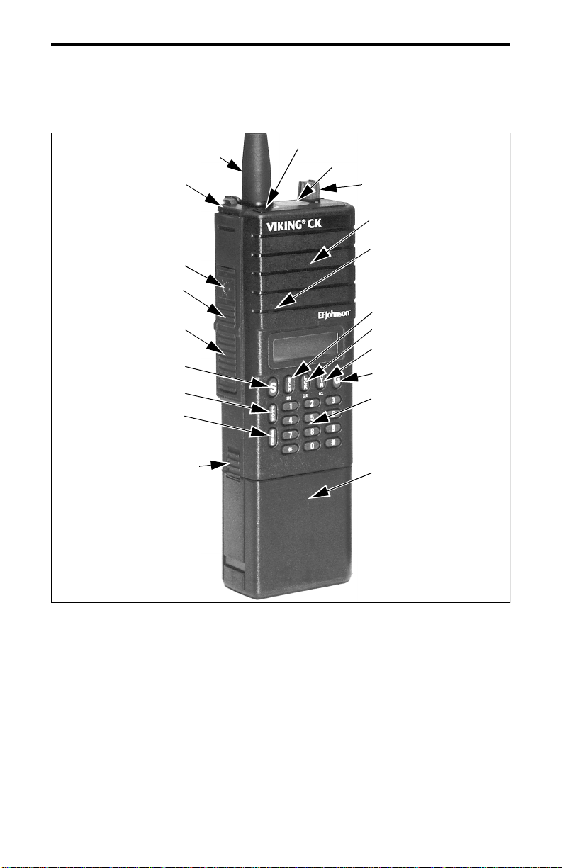
Antenna
Accessory
Connector
Backlight Switch
Auxiliary Switch
Push-To-Talk
Switch
System Select
Phone Mode Select
Send Key
Battery Release
Button
Transmit Indicator
Emergency Button
On-Off/Volume
Speaker
Microphone
Scan Key (Store)
Lock Key (Clear)
Return Key (Recall)
Group Select
Telephone Keypad
Battery Pack
FRONT PANEL CONTROLS
On-Off/Volume -Turning this knob clockwise turns power on and sets
the volume. Turning it counterclockwise to the detent turns power off.
Power is on when information appears in the display. Refer to “Setting
Volume Level” on page 38 for more information.
Emergency Button - This switch is used to manually or automatically
place a high priority call. Refer to “Emergency Button” on page 26 for
more information.
9
Page 10

CONTROLS
S (System) - Pressing this key increases the selected system. Holding it
down causes the function to repeat. Only programmed systems can be
selected. Turning power on with this switch pressed changes the loudness
of the clear-to-talk tone.
G (Group) - Pressing this key increases the selected group. Holding it
down causes the function to repeat. Only programmed groups can be
selected.
SCN (Scan) - Turns the scan feature on and off. Scan is enabled when
“SCN” is indicated in the lower part of the display. Scanning is actually
occurring when “IN SCAN” is indicated in the upper part of the display.
Turning power on with this key pressed enables/disables the key press
tone.
LCK (Lock) - Used to lock systems out of the scan list so that they are
not scanned. Also adds locked out systems or groups back into the scan
list. Pressing this key changes the status of whatever system or group was
selected last. The system or group is locked out and not scanned if is
indicated next to “SYS” or “GRP”. Turning power on with this switch
pressed enables/disables the keypad.
RTN (Return) - Is programmed to select either the home or last active
system/group.
Push-To-Talk (PTT) Switch - Pressing this switch turns the transmitter
on as indicated by in the display and a lighted transmit indicator on
TX
the top panel. This switch is the lower half of the rubber switchpad on the
side.
Auxiliary Switch - Pressing this switch with a Multi-Net system selected
temporarily suspends system or group scanning. Pressing it twice halts
scanning until it is again pressed twice or scanning is re-enabled by the
SCN key. Pressing it with a conventional system selected enables the
monitor mode. This switch is the lower part of the upper half of the
rubber switchpad on the side.
10
Page 11

CONTROLS
Backlight Switch - Pressing this switch illuminates the display so that it
can be viewed in low-light conditions. This switch is the upper part of the
upper half of the rubber switchpad on the side.
Speaker and Microphone - The internal speaker and microphone are
located behind the grille in the locations shown.
Battery Pack - Rechargeable nickel-cadmium (Ni-Cd) battery pack.
OPTIONAL KEYS FOR TELEPHONE CALLS
NOTE: Refer to “SPECIAL CALLS” o n page 15 for more information on
the following keys.
Telephone Keypad - 0-9, *, and # keys for dialing the telephone number.
PHON (Phone) - Turns the phone mode on and off.
SND (Send) - This switch can be used instead of the PHON key to select
the phone mode. The system and group preprogrammed for telephone
calls are then automatically selected. Pressing this switch after the phone
mode is selected transmits the telephone number in the display.
NOTE: The next three keys are dual-function keys which operate as
follows when t he phone mode is selected and as described in the
preceding information when the standard mode is selected.
STO ( SCN) - Pressing this key and then a number key from 1-8 stores
the number in the display in that memory location.
CLR (LCK) - Pressing this key erases the last digit in the display.
Holding this key down causes function to repeat. Pressing RCL and then
CLR erases the entire number.
RCL (RTN) - Pressing this key steps through the numbers stored in
memory. Pressing this key and then the number of a memory location
from 1-8 recalls the telephone number stored in that location.
11
Page 12
DISPLAY INFORMATION
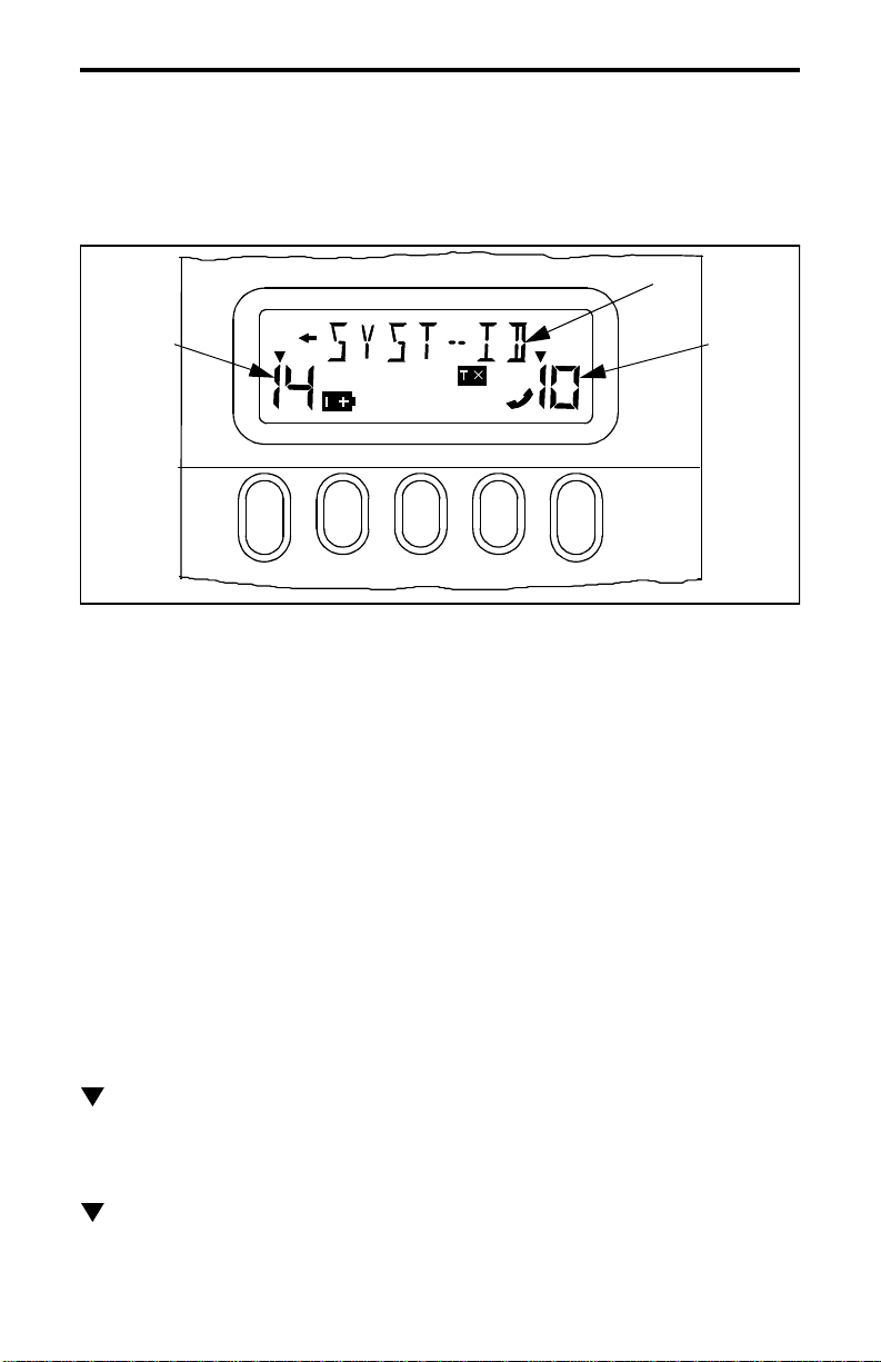
DISPLAY INFORMATION
Alphanumeric
System
Display
SYS
MUTE
S
C
N
SCN
BUSYCALLMON
L
C
K
RCLCLRSTO
PHON
R
T
N
GRP
GS
FRONT PANEL DISPLAY
System Display - Indicates the selected system number.
Group D isplay - Indicates the selected group number.
SYS (System) - Always displayed above the system number.
GRP (Group) - Always displayed above the group number.
Display
Group
Display
SCN (Scan) - Indicates that the scan mode has been selected by the SCN
key.
CALL - Indicates that a call has been received and not answered. To turn
this indicator off, press any key except backlight.
(SYS) - This indication next to “SYS” indicates that the displayed
system has been locked out of scanning by the LCK key. This indication
appears while scanning if any system has been locked out of the scan list.
(GRP) - This indication next to “GRP” indicates that the displayed
group has been locked out of the scan list by the LCK key. This indica-
12
Page 13

DISPLAY INFORMATION
tion appears when system or group scanning if any group has been locked
out of the scan list.
MUTE - Indicates that the key press tone has been muted by turning
power on with the SCN key pressed. To re-enable this tone, turn power
on again with the SCN key pressed.
TX - Indicates that the transmitter is on. This indication appears in
conjunction with the red transmit indicator next to the antenna.
BUSY - Indicates that the channel is busy when a conventional system is
selected.
MON - When a conventional system is selected, indicates that the
monitor mode has been enabled by pressing the Auxiliary switch on the
side. This disables Call Guard® squelch so that all messages are heard.
Press the Auxiliary switch again to disable monitoring.
PHON - Indicates that the phone mode has been selected by pressing the
PHON or SND key (telephone keypad models only).
- Indicates that the displayed group is programmed for telephone
calls.
- Indicates that the battery needs recharging.
- Indicates that there are overflow digits because the telephone
number is longer than 7 digits. To momentarily display the overflow
digits, press RCL 0.
Alphanumeric Display - In the standard (non-phone) mode, this display
indicates either the 7-character system identification or the 5-character
group identification. Programming determines which is displayed, and
the group identification is available on Multi-Net systems only. In the
phone mode, this display indicates the telephone number. Operating
modes and error conditions may also be indicated by this display as
described in “Display Messages” on page 38.
13
Page 14

STANDARD CALLS
STANDARD CALLS
Introduction
Most calls that you make to others in your radio system are standard
calls. When these calls are placed, all that is required is to select the
desired system and group. No number needs to be entered on the telephone keypad as with special calls. Calls in the conventional mode are
always standard calls.
Placing a Standard Call
1. Turn power on and set the volume as required.
2. Select the desired system and group if applicable.
3. If a conventional system is selected, the channel must be monitored
before transmitting. Refer to page 30 for more information.
4. Press the push-to-talk switch on the side of the transceiver and begin
talking.If a Multi-Net system is selected, a clear-to-talk tone sounds to
indicate when the system has been successfully accessed and speaking
can begin. Refer to “Clear-To-Talk Tone” on page 20 for more
information.
5. Release the push-to-talk switch as soon as the message is complete and
listen for a response. The push-to-talk switch must be pressed to talk
andreleasedtolisten.
Receiving a Standard Call
1. Turn power on and set the volume level as required.
2. Select the desired system and group if applicable.
3. After the message is received,press the push-to-talk switch on the side
of the transceiver and respond. This switch must be pressed to talk and
released to listen. If scanning, you should respond before scanning
14
Page 15

SPECIAL CALLS
resumes which is programmable for 1-7 seconds after the message
ends. If you do not, another call may be received and you may have to
change the system a nd group. Refer to “Transmitting In Scan” on
page 22 for more information.
SPECIAL CALLS
Introduction
Special calls include telephone calls, calls to specific mobiles or a
dispatcher, calls to other Multi-Net sites, and others. These calls differ
from standard calls in that a special number must be dialed after the
system is accessed. This number is dialed using the optional DTMF
keypad on the front panel of the transceiver.
NOTE: Special calls can be placed and received only if your transceiver
has been programmed for that service by your system operator.
Placing a Special Call
1. Turn power on and set the volume level as required.
2. Select the system and group programmed for the special call you are
making. When a group programmed for telephone calls is selected, the
handset symbol appears in the display.
3. Select the phone mode by pressing the PHON or SND keys. The phone
mode is indicated by “PHONE” in the display.
4. If you are m aking a telephonecall, dial the telephone number.If you are
making other calls, a number containing 4-8 digits is dialed. Your
system operator will tell you what number you are to dial for each
special call you can make. You may also be able to recall the number
from memory as described in the following information.
5. Momentarily press the push-to-talk switch to acquire a dial tone. Then
press the SND key to transmit the number in the display.Release the
15
Page 16

SPECIAL CALLS
push-to-talk switch (if it is pressed) and a short tone should sound to
indicate that the call was accepted by the system. After this tone
sounds, a ringing or second short tone sounds as follows:
A ringing tone indicates that the other party is being rung. If it is a telephonecall and the line i s busy, a busy tonemay also sound. In thiscase,
terminate the call by pressing the # key. When the party answers,
continue the call as described in step 6.
A second short tone indicates that the path is complete and you should
transmityourmessage.Noringingofthe otherparty occurs.Proceedas
follows:
6. Pressthepush-to-talkswitchtotalkandreleaseittolistenaswithstan-
dard calls. Since the path is one way, you will not hear the other party
while the push-to-talk switch is pressed.
7. When the conversation is finished, the call should be terminated by
sending the # character. This character is sent automatically when you
exit the phone mode by pressing the PHON key. It can also be sent by
pressing the # key. Three beeps indicate that the call has been
terminated.
Receiving a Special Call
1. Turn power on and set the volume level as required.
2. Special calls are usually received regardless of the group selected if a
system programmed for Multi-Net operation is selected or scanned.
However, some calls may require that a certain system and group be
selected. If so, your system operator will tell you which to select.
3. When “ringing” is heard, answer the call in the normal manner (press
the push-to-talk switch to talk andrelease it to listen).It is not necessary
to select the phone mode to receive a special call.
4. When the call is finished, it is usually terminated by the originating
party. If you do not hear the three rapid beeps which indicate t ermination, press the # key to terminate the call.
16
Page 17

SPECIAL CALLS
Landside-Originated Calls
Mobiles can also be called from a landside telephone. If the system
is designed so t hat mobiles can be called directly, simply dial the telephone number of the mobile being called. If mobiles cannot be called
directly, dial the number of the system. Then when the system answers,
dial the special number which specifies the mobile being called. This
number is supplied by your system operator, and it must be dialed using a
tone-type telephone. Depending on the type of call, a ringing tone then
sounds or a second tone sounds which indicates speaking can begin.
Operation is similar to that described in “Placing a Special Call” on
page 15.
Additional Phone Mode Information
Phone Mode
When the phone mode is selected by pressing the PHON or SND
keys, “PHONE” appears in the lower part of the display and the group or
system identification is cleared so that the phone number can be
displayed. In addition, the SCN, LCK, and RTN keys become STO, CLR,
and RCL keys. Group scan is also disabled if it is programmed, causing
calls to be received on the displayed group only. To exit the phone mode,
press the PHON key (the SND key cannot be used).
When the phone mode is not selected, the number keys dial a
number only when the push-to-talk switch is pressed. In addition, the
dialed number does not appear in the display, so it cannot be stored or
recalled. When the phone mode is exited, any phone number in the
display is erased and cannot be redisplayed unless it was stored in
memory. The transceiver always goes into the standard mode when
power is turned on.
Entering the phone mode using the PHON or SND key results in
slightly different operation. When the PHON key is used, the displayed
system and group do not change when entering as well as exiting the
phone mode. When the SND key is used, the system and group preprogrammed for telephone calls are automatically selected when the phone
17
Page 18

SPECIAL CALLS
mode is entered. Then when the phone mode is exited by pressing the
PHON key, the system and group that were displayed when the phone
mode was entered are again displayed. The system and group may be
changed in either mode by pressing the SYS or GRP keys.
Dialing The Number
The phone mode allows you to enter the telephone or mobile number
at any convenient rate, correct any dialing errors, and then transmit the
number when desired by pressing the SND (Send) key. Toerase the last
digit entered, press CLR. Holding the key down erases the number one
digit at a time. To erase the entire number, press RCL CLR.
Numbersupto14digitsinlengthcanbeenteredinthismode.
However, only the last 7 digits are displayed. When there are overflow
digits, an arrow appears on the left side of the telephone number. To
momentarily display the overflow digits, press RCL 0. The RCL key can
also be used to step through the programmed telephone numbers,
including overflow digits.
Numbers can be dialed in the phone mode without changing the
number in the display. Simply dial the number while the push-to-talk
switch is pressed. This also allows access to special services which
require numbers to be dialed after the connection is made. Telephone
calls can also be placed without selecting the phone mode by dialing the
number with the push-to-talk switch pressed.
Storing and Recalling Telephone Numbers From Memory
Up to 8 telephone or other numbers can be stored in memory and
then later recalled. This eliminates the need to re-enter frequently called
numbers. Each of these numbers can be up to 14 digits in length. To store
a number, select the phone mode and enter the telephone number as
described in the preceding section. Then press STO and a number key
from 1-8 to select the memory location where the telephone number is
stored. The * symbol can be stored, but is sent normally without a pause.
If the # symbol is stored, it will terminate the call when it is sent. To
recall a telephone number,press RCL and then the memory location from
18
Page 19

SUPERVISORY TONES
1-8. The number can then be changed if necessary and then transmitted
by pressing SND.
Telephone numbers can also be programmed by your system operator. A unique identification can then be stored in the unused positions of
each 14-character location. For example, if the number has seven digits,
the seven-character identification “RICHARD” can be stored with the
number. Then when the number is recalled, “RICHARD” is flashed in the
display followed by his telephone number. Each number programmed by
your system operator can also be programmed so that you cannot change
it. I f you do change a number with a unique identification, the identification is erased and cannot be reprogrammed from the keypad. You must
take the transceiver back to your system operator to have the identification reprogrammed.
Terminating a Call
When a conversation is finished, it is good practice for one of the
parties to terminate the call by transmitting the # character. When the
phone mode is exited by pressing the PHON key, this character is sent
automatically. The # key can also be pressed to send this character. Three
beeps sound to indicate that the system has detected the end of the call.
Terminating the call in this manner prevents additional billing that may
occur for the time it takes the system to automatically detect the end of a
call.
SUPERVISORY TONES
NOTE: The following tones are heard at various times when operating
this transceiver. The tones are heard only when a Multi-Net system is
selected unless noted otherwise.
Intercept Tone
This is a siren-like tone (alternating high and low tones) which indicates the following error conditions:
19
Page 20

SUPERVISORY TONES
• If this tone sounds after the transmit indicatorflashesseveral times and
“NO SITE” appears in the display, an out-of-radio-range condition is
indicated. To complete a call, you may need to get closer to your radio
system. Once this tone sounds, no more access attempts are made until
the push-to-talk switch is released and then pressed again.
• If this tone sounds after the transmitter has been on for an extended
period and “TX TIME” also appears in the display, the transmitter has
been disabled by the time-out timer feature. Refer t o page 25 for more
information.
• Ifthistone sounds as soon as the push-to-talkswitchispressed and “TX
DSBL” appears in the display, a channel is selected in the conventional
mode that is programmed as receive-only. Refer to page 31 for more
information.
Clear-To-Talk Tone
This is a short tone which sounds when the push-to-talk switch is
pressed. It indicates that the system has been successfully accessed and
speaking can begin. This tone does not sound if the radio system is busy
or if the selected system is programmed for conventional operation. Refer
to “Clear-To-Talk” on page 24 for more information.
Key Press Tone
This is a short tone that sounds when a key is pressed. This tone can
be enabled and disabled by turning power on with the SCN key pressed.
NOTE: The following tones are heard only when making telephone calls.
Confirmation Tone
This is a short tone that sounds when the number just dialed is
accepted by the s ystem.
20
Page 21

SYSTEM SCAN
Call Proceed Tone
With certain non-telephone calls, ringing does not occur after the
number is dialed. Instead, another short tone sounds after the confirmation tone to indicate that the audio path is complete and speaking can
begin.
End Call Tone
This tone consists of three beeps, and it indicates that the end of the
call has been detected by the system.
Proceed Dialing Tone
When placing a landside-originate call to a mobile (see “LandsideOriginated Calls” on page 17), the landside caller may dial the system
and then enter a special number which specifies the mobile being called.
If placing this type of call, this tone sounds when the system answers to
indicate that the special number should be dialed.
SYSTEM SCAN
General
NOTE: In some cases, such as if your transceiver is programmed with
only one system or if calls are received on only one system, you may
decide not to use the system scan feature.
System scanning is turned on by pressing the SCN key. The scan
mode is indicated by “SCAN” in the lower part of the display. When
scanning is actually occurring, “IN SCAN” appears in the upper part of
the display in place of the unique system identification. In addition, the
system and group numbers are replaced by dashes.
Scanning is sequential through the programmed systems unless they
are locked out as described i n “System and Group Lockout”. When an
incoming call is detected, scanning stops and the call is received. The
21
Page 22

SYSTEM SCAN
display always changes to the system of the call and usually changes to
the group of the call. The selected system or group can be changed while
scanning by simply pressing the system or group select switch. Scanning
then halts and the selected system or group changes. Scanning resumes
1 second after a switch is released.
Some transceivers may be programmed so that the conventional and
some Multi-Net systems may not be scanned. If this is the case with your
transceiver , your system operator will tell you which systems are not
scanned.
Scan Resume Delay
After a message is received or transmitted in the scan mode, there is
a delay period of 1-7 seconds before scanning resumes. The exact length
of this delay is programmed by your system operator. When a message is
received, this delay prevents another message from being received before
a response can be made. If a response is not made during this delay
period, the selected system and group may have to be changed (refer to
next section). When a message is t ransmitted, this delay ensures that a
response to your message is heard instead of some other message occurring on another system or group.
Transmitting In Scan
When you transmit while scanning (dashes in both the system and
group displays), the transmission always occurs on the revert system/
group. This is the system and group that were displayed when scanning
was turned on. To display the revert system and group while scanning,
temporarily halt scanning by pressing the SCN key, Auxiliary switch, or
PTT switch. If a message is received while scanning, scanning stops and
the system and group of the call are displayed. If the transmitter is keyed
to respond to this call, Floating/Fixed Revert programming determines
the system and group on which the transmission occurs:
Floating - When Floating Revert is programmed, you can always
respond to the call without having to change the selected system/
group as long as you do so before the scan resume delay expires (see
22
Page 23

SYSTEM SCAN
preceding section). For example, if System 1/Group 2 were displayed
when scanning was turned on and a call is received on System 3/
Group 4, System 3/Group 4 are displayed and the call is received. If a
response is then made to that call, the transmission occurs on System
3/Group 4. However, if the response is not made until after scanning
resumes, the transmission occurs on the revert system/group (System
1/Group 2 in this case). This configuration may be programmed if
while scanning, responses must be made to messages occurring on
different systems and groups.
Fixed - When Fixed Revert is programmed, the transceiver always
transmits on the revert system/group, even when responding to a call.
Therefore, if Fixed Revert was programmed for the preceding
example, the transmission would occur on System l/Group 2, not
System 3/Group 4. To respond to the call, the selected system/group
would have to be changed manually using the System and Group keys.
The system/group of a call can also be made the revert system/group
by turning off scanning before scanning resumes. This configuration
may be programmed if you normally only monitor other calls while
scanning and most transmissions occur on the revert system/group.
System and Group Lockout
Systems and groups can be locked out of system and group scanning
by the LCK key. Pressing this key changes the lockout status of the
system or group that was changed last. For example, if System 2 is
selected by pressing the “S” switch and then LCK is pressed, System 2 is
locked out of scanning (if it was unlocked). Then if LCK is pressed again,
System 2 is unlocked and so on.
A locked out system is indicated by next to “SYS” in the display,
and a locked out group is indicated by the same symbol next to “GRP”.
When system scanning (“IN SCAN” displayed), the system lockout indication is displayed if any system is locked out. Likewise, the group
lockout indication is displayed if any group in a scanned system is locked
out. To check which system or groups are locked out, halt scanning by
pressing the SCN or Auxiliary switches. Then step through the
programmed systems and groups while watching the lockout indicators.
23
Page 24

OTHER FEATURES
System lockout is not available if you have only one selectable
system, and group lockout is available only if the selected system is
programmed for group scan (see page 25). The lockout status of all
systems and groups is maintained when power is turned off.
Scanning Multi-Net Systems
NOTE: For information on Multi-Net and conventional systems, refer to
page 29.
When Multi-Net systems are scanned, calls are received on all
selectable groups if Group Scan is programmed, and on only the lastselected group if it is not programmed. Your transceiver may also be
programmed with f ixed groups. Calls on these groups are normally
received regardless of system and group scanning.
Scanning Conventional Systems
Group scan is not available with conventional systems. Therefore,
calls are received on only the last-selected group of conventional
systems. For example, if Groups 1-4 are programmed in a conventional
systemandGroup2isthelastselectedordisplayedgroupinthatsystem,
Group 2 is the only group on which calls are received in that system.
If a group is programmed with Call Guard squelch, only messages
intended for you will be detected on that group while scanning. However,
if Call Guard squelch is not programmed or is disabled by the monitor
mode selected by the Auxiliary switch, any message occurring on that
group will be heard. Refer to “CONVENTIONAL MODE OPERATION”
on page 30 for more information.
O THER FEATURES
Clear-To-Talk
When a system programmed for Multi-Net operation is selected, a
short beep sounds when the push-to-talk switch is pressed. This tone indi-
24
Page 25

OTHER FEATURES
cates that the radio system has been successfully accessed and speaking
can begin. If no tone sounds and “BUSY” is indicated in the display, the
system is busy. If you continue to hold down the push-to-talk switch, the
system will be accessed and the clear-to-talk tone will sound when the
system is available. If the selected system is programmed for conventional operation, the clear-to-talk tone does not sound. Therefore, you can
begin speaking as soon as the push-to-talk switch is pressed (after monitoring the channel). A standard or loud clear-to-talk tone can be selected.
To change the tone, turn power on with the “S” key pressed.
Group Scan
With the Group Scan feature, calls are received on all the selectable
groups of a Multi-Net system regardless of which is selected. The display
also changes to the group on which a call is received. Without Group
Scan, calls are received on only the selected group. Group Scan is
enabled or disabled by your system operator on each Multi-Net system. If
programmed, it is active whenever the system is selected or scanned
(system scan does not need to be on). Group Scan is not available on
conventional systems, and it is disabled when the phone mode is selected.
When system scan is turned off, group scan is indicated by a dash in
the Group display (the System display continues to indicate the selected
system). When system scan is occurring, dashes appear in both the
System and Group displays even if group scan is not programmed.
Groups can be locked out of scanning using the LCK key (refer to
“System and Group Lockout” on page 23).
Time-Out Timer
There is a Time-Out Timer feature which automatically disables the
transmitter if it is continuously on for longer than the programmed time.
If this timer times out, the transmitter is disabled, the intercept tone
sounds, and “TX TIME” is displayed. It is programmed by your system
operator for a time from 0.5-5.0 minutes. The timer and tone are reset by
releasing the push-to-talk switch. This timer prevents a blocked channel
caused by an accidentally keyed transmitter and also possible transmitter
damage caused by transmitting for extended periods.
25
Page 26

OTHER FEATURES
Call Indicator
The call indicator is the word “CALL” in the lower part of the
display. This feature indicates that a call was received while you were
away from the transceiver. It is programmed by your system operator to
turn on when calls are received on certain groups (Multi-Net systems) or
channels (conventional systems). It may also be disabled entirely. This
indication is turned off by pressing any key except backlight. Transceiver
power must be on for this indicator to operate.
RTN (Return) Key
The RTN key is used to quickly display either the “home” or last
active system/group. Programming by your system operator determines
which is selected and also the length of time it is displayed. The system/
group may be displayed briefly (1-7 seconds) or indefinitely so that it is
the new selected system/group. If scanning when the RTN key is pressed,
scanning halts and either the home or last active system/group is
displayed. In addition, when this key is programmed to display the home
system/group, the revert (selected) system/group is also displayed. If the
system/group is displayed indefinitely, scanning automatically turns off.
When the system and group are displayed temporarily, the system and
group that are displayed can be made the selected system and group by
pressing any function key. Pressing the RTN key twice also has this
effect.
Emergency Button
When equipped with this optional switch, high-priority calls can be
placed. This switch can be programmed by your system operator for
manual or automatic operation. When manual operation is programmed,
no call is placed automatically. However, a specific system/group is
selected and the transceiver goes into a high-priority m ode that minimizes, as much as possible, the chance that the system will be busy when
a call is placed. W hen automatic operation is programmed, the transceiver automatically transmits an emergency message on a specific
system and group at a high priority until an acknowledgment is received
26
Page 27

OTHER FEATURES
from the dispatcher. A short tone sounds when this key is pressed.
Contact your system operator for more information on the operation of
this switch.
Transmit Inhibit
The Transmit Inhibit feature prevents the transmitter from turning on
if the party you are calling is busy with another call. When the transmitter
is disabled by this feature, the intercept tone also sounds and “TX
INHIB” appears in the display. This feature is programmed by your
system operator on Multi-Net systems only.
To make another call attempt when the transmitter has been disabled
by this feature, the push-to-talk switch must be released and then pressed
again. However, since a 5-second time period must expire, you may want
to wait a few seconds before making another call attempt. One use of this
feature is to provide an audible indication that the party you are calling is
busy.
Priority Calls
Your transceiver can be programmed so that certain incoming calls
have priority over other calls you may be receiving. Therefore, if a higher
priority call is detected while you are listening to another call, the current
call is immediately dropped and the priority call is received.
If a first priority call is received, “RX PRI1” is displayed, and if a
second priority call is received, “RX PRI2” is displayed. A priority 1
message can interrupt a priority 2 message. To turn off the priority indication, press any key except backlight. Priority calls occur only on MultiNet and LTR systems, and they are received regardless of the group that
is selected (as long as the system programmed for those calls is selected
or scanned).
Keypad Disable
If you are having problems with front-panel keys being accidentally
pressed, such as when the transceiver is carried on a belt, the keypad can
27
Page 28

OTHER FEATURES
be disabled. To disable all keys except push-to-talk and backlight, turn
power on with the LCK key pressed. If a key is then pressed, all that
happens is that “KEYLOCK” is displayed. To re-enable the keypad,
simply turn power on again with the LCK key pressed.
Key Press Tone Disable
If the tone that sounds when a key is pressed is distracting or
annoying, it can be disabled. To enable or disable this tone, turn power on
with the SCN key pressed. When the key press tone is disabled, “MUTE”
is displayed.
High/Low Power Select
Some transceivers have selectable high and low power output (your
system operator will tell you if yours does). If your transceiver has this
feature, power output is changed by turning power on with the RTN key
pressed. Either HI PWR or LOW PWR is then flashed in the display to
indicate which power setting is currently selected. The low power setting
may increase battery life but decrease range. The opposite may occur
with the high power setting. If your transceiver does not have selectable
power output, this information is still indicated even though no power
change occurs.
28
Page 29

MULTI-NET AND CONVENTIONAL MODES
MULTI-NET AND CONVENTIONAL
MODES
General
This transceiver can operate in both the Multi-Net and conventional
modes. Each selectable system can be programmed for either type of
operation. The type of operation that is programmed is determined by the
type of radio equipment in use in the radio system you are accessing. You
can probably assume that Multi-Net operation has been programmed
unless you are told otherwise. The differences in operation are described
in the information which follows and also noted elsewhere in this manual
as required.
Channel Monitoring
In the Multi-Net mode, channel monitoring is performed automatically by the transceiver. In the conventional mode, it must be performed
manually as described in the “Monitoring Before Transmitting” description which follows.
Supervisory Tones
In the Multi-Net mode, supervisory tones indicate clear-to-talk and
out-of-range conditions. In the conventional mode, a busy condition is
detected by manually monitoring the channel, and an out-of-range condition probably exists if you are unable to get a response from the party you
are calling.
Group Select
In the Multi-Net mode, the group key selects ID codes; in the
conventional mode it selects radio channels.
29
Page 30

CONVENTIONAL MODE OPERATION
CONVENTIONAL MODE OPERATION
Monitoring Before Transmitting
Before transmitting in the conventional mode, regulations require
that you monitor the channel to make sure that it is not being used by
someone else. If you were to transmit while someone else was talking on
the channel, you would probably disrupt their conversation.
The simplest way to monitor the channel is to note if “BUSY” is
indicated in the lower part of the display. If it is not, the channel is not
being used and you can transmit your message. There may be periods
when this indication is displayed and no one is using the channel. Therefore, other methods to monitor the channel are as follows:
If Call Guard squelch is not used on the channel (refer to description
page 31), monitoring can be performed by simply listening for someone
talking before pressing the push-to-talk switch.
If Call Guard squelch is programmed, it must be disabled so that all
calls can be heard. To disable Call Guard squelch, press the Auxiliary
switch on the side of the transceiver. This turns on the monitor m ode
which is indicated by “MO N” in the lower part of the display. To reenable Call Guard squelch, press the Auxiliary switch again so that
“MON” is not displayed.
Transmit Disable When Busy
The transceiver can be programmed so that the Transmit Disable
When Busy feature automatically disables the transmitter if the channel is
busy (“BUSY” indicated in the lower part of the display). If the channel
is busy with this feature programmed and the push-to-talk switch is
pressed, the transmitter does not turn on and the channel can be monitored for as long as the push-to-talk switch is pressed.
In some systems, “BUSY” may be indicated and the transmitter
disabled even though no one is talking. In this case, the transmitter can be
30
Page 31

CONVENTIONAL MODE OPERATION
turned on by quickly releasing and then pressing the push-to-talk switch.
If “MON” is indicated in the display as described in the preceding
section, the transmitter will turn on even if the channel is busy. When this
feature is disabled, the transmitter always keys, even if the channel is
busy.
Receive-Only and Talk-Around Channels
Receive-only channels can be programmed in the conventional
mode by your system operator to allow monitoring but not transmitting
on certain channels. If the push-to-talk switch is pressed with a receiveonly channel selected, the intercept tone sounds and “TX DSBL” is
displayed.
Talk-around channels (groups) can be programmed by your system
operator to allow you to talk directly to another mobile without going
through a repeater (both Multi-Net and conventional calls normally go
through a repeater). This may permit communication when it would
otherwise not be possible such as when you are out of range of the
repeaters. This feature is available on conventional systems only.
Call Guard Squelch
The Call Guard Squelch feature eliminates distracting calls intended
for others using the channel. This is done by using a subaudible tone or
digital code to control the squelch. This tone or code is unique to you or
your group on that channel. Call Guard squelch is a programmable
feature available in the conventional mode only. (The Multi-Net mode
uses ID codes to eliminate calls intended for others.)
31
Page 32

OPERATION WITH OPTIONAL REMOTE CONTROL UNIT
OPERATIONWITHOPTIONAL
REMOTE CONTROL UNIT
Power
Switch
Volume
Up/Down
Switches
System/Group
Identification
System
Up/Down
Switches
System
Number
Group
Up/Down
Switches
Group
Number
Volume
Level
Introduction
This transceiver can be converted to a mobile transceiver by plugging it into the optional vehicle adapter if it has been installed in the
vehicle. This adapter also provides rapid recharging of the transceiver
battery.
The optional Remote Control U nit shown above can be used with
the adapter to operate the transceiver. Most controls on the control unit
and transceiver operate in parallel, so both can be used if desired. Two
32
Page 33

OPERATION WITH OPTIONAL REMOTE CONTROL UNIT
additionalfeatures available with a control unit are a power turn-off delay
and horn alert. The operation of the Remote Control Unit with this transceiver is described in the following information.
Control Unit Controls
PWR - Turns both control unit and transceiver power on and off. Power
is also controlled by the vehicle's ignition switch. Therefore, that switch
must also be on to turn power on. The transceiver on-off switch and
volume control are nonfunctional when the control unit is used.
VOLUME - Pressing the upper VOLUME switch increases the volume
level by one step, and pressing the l ower switch decreases the volume
level by one step. Holding either switch down causes the function to
repeat. The volume level is indicated by a bar graph on the right side of
the display.
NOTE: The equivalent transceiver key is shown in parentheses in the
following descriptions.
SYSTEM (S) - Pressing the upper SYSTEM switch increases the
selected system number by one, and pressing the lower switch decreases
the selected system number by one. Holding either switch down causes
the function to repeat. The selected system is indicated in the display
above the switch.
GROUP (G) - Functions like the SYSTEM switch to select the desired
system.
SCAN (SCN) - Turns scanning on and off. Scanning is on when “SCN”
is indicated in the display.
LOCK (LCK) - Locks systems and groups out of the scan sequence. The
lockout indicator is the word “LOCKOUT” in the display. Small arrows
on either side of this word indicate if the system and/or group is locked
out.
P1 (PHON) - Turns the phone mode on and off.
33
Page 34

OPERATION WITH OPTIONAL REMOTE CONTROL UNIT
P2 (RTN) - Selects either a home system/group or the last active system/
group, depending on programming by your system operator. In the phone
mode, this key is used to sequentially recall telephone numbers from
memory.
MON (Auxiliary) - Turns the monitor mode on and off when a conventional system is selected. This key and the AUX key perform the same
function
HORN - Turns the horn alert on and off if i t has been installed.
CALL (SEND) - Selects the phone mode or if already in the phone
mode, transmits the telephone number in the display.
STATUS - Selects the status message to be sent. Refer to “Sending Status
Information” on page 36 for more information.
EMER (Emergency Button) - Used to manually or automatically place
a high-priority call. Refer to “Emergency Button” on page 26 for more
information.
AUX (Auxiliary) - Turns the monitor mode on and off when a conventional system is selected. This key and the MON key perform the same
function.
Miscellaneous Operating Information
Microphone Hanger - The microphone hanger controls the monitor
mode similar to the Monitor key (off-hook = monitor). In addition, taking
the microphone off-hook disables system and group scanning if it is
enabled.
Telephone Calls - The phone mode can be selected by the P1 key and
numbers can be sequentially recalled from memory by pressing the P2
key. This can be done even if the transceiver is not equipped with the
optional telephone keypad. However, that keypad is required to enter
numbers into the display or store numbers in memory (a microphone
34
Page 35

OPERATION WITH OPTIONAL REMOTE CONTROL UNIT
keypad cannot be used). If the number is dialed using the microphone
keypad, the phone mode probably does not need to be selected.
Turning Power On and Off - Power to both the transceiver and control
unit is controlled by the control unit PWR switch. However, the vehicle’s
ignition switch also normally controls power. Therefore, it must be in the
ON or ACCESSORY position for power to turn on. When the ignition
switch is turned off and power has not been turned off by the PWR
switch, power remains on for the programmed delay period (see next
description). The control unit can also be installed so that the ignition
switch does not control power. Power is then controlled by only the PWR
switch and the turn-off delay is not available.
Turn-Off Delay - When the ignition switch controls power as described
in the preceding paragraph, there is a turn-off delay that can be
programmed by your system operator. This delay can be 0, 10, 20, or 30
minutes, 1, 2, or 4 hours, or an infinite time (no turn-off occurs). The
delay period begins when the ignition switch is turned off with the
control unit power on. It can be canceled by turning power off using the
PWR switch or turning the ignition switch back on. This delay can be
used to keep functions such as the Call indicator, horn alert, and battery
charger functional for a limited time after the vehicle is turned off. It can
also be used to prevent accidental discharge of the vehicle battery.
Horn Alert - The vehicle’s horn or some other type of alert can be used
to signal an incoming call. It can be programmed to activate when calls
are received on specific groups or channels. When a call is received that
activates the horn alert, the horn sounds once per second for 3 seconds
and then deactivates. The horn alert is turned on and off by the HORN
button on the control unit. It is enabled when “HORN” is displayed.
Other requirements for the horn to sound are that the vehicle’s ignition
switch must be turned off and the control unit must be in the delay period
described in the preceding section.
Control Unit Display - The control unit displays the same unique 7-character system or 5-character group identification as the transceiver display.
Other information displayed in that area of the transceiver display is also
indicated by the control unit display. The control unit display and keys
35
Page 36

MISCELLANEOUS INFORMATION
are continuously lighted (when power is on) for use in low-light
conditions.
Sending Status Information
When the remote control unit is used, status information can be
transmitted to your dispatcher when a Multi-Net system is selected. If this
feature has been programmed by your system operator, one of up to eight
status conditions can be selected using the STATUS key. The currently
selected status condition is transmitted whenever the transmitter is keyed.
To momentarily display the currently selected status, press the STATUS
key once. To change the status, press this key again while this information is displayed. This cycles through the available choices. For example,
status conditions such as AT SITE, LVG SITE, or UNLOADING can be
displayed. This information is not displayed by the transceiver display.
MISCELLANEOUS INFORMATION
Auto-Registration
In some radio systems, several sites may be linked together to
provide wide area coverage. The auto-registration f eature may then be
used so that special calls can be automatically routed to the correct site
(standard calls are not routed to other sites). To have this feature, it must
have been programmed by your system operator and system scanning
must be enabled by the SCN key. Auto-registration is available with
Multi-Net systems only.
Auto-registration operates as follows: When you move out of range
of the current site, the transceiver automatically begins searching for
another site. While it is searching, “SCN” flashes in the display. When a
new site is located, “SCN” is again displayed continuously and the
selected system/group changes to the new site. The new system is typically the first system that is programmed for the new site, and the new
group is the group that was displayed when that system was last selected.
36
Page 37

MISCELLANEOUS INFORMATION
Busy Queuing
The busy queuing feature places the call in a queue if the repeater
system is busy when the call is placed. Then when the system becomes
available, a tone sounds and the call can be placed if desired. Busy
queuing is either enabled or disabled on all Multi-Net systems by system
operator programming. It functions with both standard and special calls.
It is not available on LTR or conventional systems.
The Busy Queuing feature operates as follows: If the radio system is
busy, the busy tone sounds. (Without queuing, no tone sounds because the
clear-to-talk tone sounds only when a successful access is m ade.) The
queue mode is then entered automatically when the PTT switch is
released. The queue mode is indicated when “QUEUED” is displayed
and the busy tone turns off. Then when the system becomes available,
either a beeping t one or dial tone sounds. The beeping tone is heard if a
standard call is being made, and the dial tone is heard if a special call is
being made. The call can then be placed in the normal manner.
If no call is placed soon after the tone sounds, the queue mode is
automatically exited and normal operation resumes. The queue mode is
also exited if a call is received on the selected group, the system/group is
changed, the push-to-talk switch is pressed, or any other keys directly
under the display are pressed (while no call is being received).
Calls are received normally while in the queue mode. Group scanning continues if it is programmed on the selected system. However,
system scanning is temporarily disabled, so calls are not received on
other systems. If a call is received on some other group while in queue,
you can respond to the call without affecting the queued call. Normal
queuing of a call resumes shortly after the call on the other group is
finished.
System Operator Programming
As noted in the descriptions of many of the features of this transceiver, programming by your system operator may determine availability
and how they operate. If you require more information on how a partic-
37
Page 38

MISCELLANEOUS INFORMATION
ular feature operates, contact your system operator. The only userprogrammable feature of this transceiver is the seven telephone numbers
(if your transceiver is equipped with the optional telephone keypad).
However, even that may not be user programmable if the location has
been locked by your system operator (see “Storing and Recalling
Numbers From Memory” on page 18).
Setting V olume Level
This transceiver does not have a squelch control that can be turned to
enable background noise for use in setting the volume level. However, if
the key press tone is enabled, any key can be pressed and a beep will
sound that is representative of the current volume level. The index on the
volume knob can also be used to determine the current volume setting.
Display Messages
Messages may appear in the display which indicate operating modes
and error conditions. The messages that may be displayed are as follows.
Refer to the related descriptions in this manual for more information.
NO SITE - Indicates an out-of-range condition. The intercept tone also
sounds when this m essage is displayed. To correct this condition so that
calls can again be placed, you must get closer to your repeater site. This
message is not displayed in the conventional mode.
BUSY - Indicates that the system being accessed is busy. Calls cannot be
placed until the system becomes available. Refer to “Clear-To-Talk” on
page 24 for more information. This m essage is not displayed in the
conventional mode.
TX TIME - Indicates that the transmitter has been disabled by the timeout timer.
TX DSBL - Indicates that transmitting is not allowed on the selected
group because it has been programmed as receive-only. This message is
displayed in the conventional mode only.
38
Page 39

MISCELLANEOUS INFORMATION
TX INHIB - Indicates that the selected group is temporarily busy. This
message is not displayed in the conventional mode.
SYN ERR - Indicates a frequency synthesizer error. Refer to “Transceiver Service” on page 42.
PRG ERR - Indicates that no transmit frequency has been programmed
for the selected system. Refer to “Transceiver Service” on page 42.
RX PRI1 - Indicates that a call has been received on the first priority
group (see “Priority Calls” on page 27). Press any key except backlight to
turn it off. This message is not displayed in the conventional mode.
RX PRI2 - Indicates that a call has been received on the second priority
group (see preceding description).
IN SCAN - Indicates that system scanning is occurring.
KEYLOCK - Indicates that the keypad has been disabled by turning
power on with the LCK key pressed. Turn power on again with this key
pressed to re-enable the keypad.
Rechargeable Battery Pack
WARNING
Dispose of the nickel-cadmium battery pack in accordance with local
regulations. Do not dispose in fire because it may explode.
Battery Pack
NOTE: Before removing a battery pack, make sure that transceiver power
is turned off.
With proper care, a battery pack should provide many months of
service. Since the battery pack is a sealed unit, it cannot be serviced and
must be replaced whenever it fails to hold a charge or is defective for
some other reason. To remove the pack, press the spring-loaded button on
39
Page 40

MISCELLANEOUS INFORMATION
the side upward and rotate the pack counterclockwise (when viewed from
the bottom). T o install a pack, insert it in the socket and rotate it clockwise until it locks in place. A new pack must be charged before use.
Battery Operating Time
Typical operating time before recharging is required depends on
what model of transceiver you have and also how you use it. The 8560/70
models have fixed power output and the 8565 m odel has user-selectable
high and low power outputs. With the following times, it is also assumed
that 90% of the time is spent in the standby mode (receiving, audio
muted), 5% in the receive mode (audio enabled), and 5% in the transmit
mode. If more time is spent in the receive or transmit modes, the time
varies accordingly. Recharging is required when appears in the
display and a beep sounds when the push-to-talk switch is released. Do
not regularly use a pack until the transceiver becomes totally inoperative
because this can shorten battery life.
Transceiver 1400 mAH Battery (P.N. 587-8565-162)
8560/70 (fixed output) 14 hrs
8565 (low power selected) 10.5 hrs
8565 (high power selected) 8.5 hrs
Recharging
The battery pack can be recharged while it is attached to the transceiver or it can be removed and recharged. Charging time is somewhat
longer if the transceiver is left on while recharging,especially when using
the trickle charger. Approximate charge times with the various chargers
are shown below. It is assumed that the battery is discharged to the point
where the low-battery indication appears. When the rapid and vehicular
chargers are used, a steady or red indicator indicates charging in the rapid
mode and a flashing or green indicator indicates charging in the trickle
rate and an almost fully charged battery.
40
Page 41

MISCELLANEOUS INFORMATION
Charger Part Number Approximate Charge Time
Trickle 563-0001-003 16 hours
Rapid 239-5800-400/-476 2 hours
Vehicular Adapter Rapid 239-5810-500 2 hours
It is good practice to remove the battery from the charger after it is
fully charged. Regularly leaving a fully charged battery in the charger for
an extended period (such as longer than overnight or over a weekend),
may shorten battery life. In addition, the ambient temperature should be
+50° to +95° F (+10° to +35° C) when recharging a battery.
NOTE: It is recommended that one of the rapid chargers be used whenever possible (especially the new technology DT/Dt chargers listed on the
preceding page). Using those chargers normally results in longer battery
life, longer operating time, and faster recharging.
Speaking Into Microphone
For best results, hold the speaker grille about l-2 inches away from
your mouth and speak slowly and distinctly at a normal conversational
level. Do not shout since it distorts your voice and does not increase
range. Make sure the push-to-talk switch is pressed before you begin to
speak and released as soon as the message is complete.
Operation At Extended Range
When approaching the limits of radio range, the other party may not
always hear your transmissions and there may be an increase in background noise when messages are received. Communication may be
improved by moving to higher ground or away from shielding structures
such as tall buildings and hills.
FCC Licensing
To operate this transceiver on the air, it is usually necessary to file
the proper license application. Your system operator will provide you
with the necessary information regarding licensing requirements.
41
Page 42

INTRINSICALLY SAFE CLASSIFICATION
Transceiver Service
If the transceiver is not operating properly, “SYN ERR” or “PROG
ERR” may be displayed. It is also possible that all segments of the
display are indicated when power is turned on. To attempt to clear this
condition, turn the power off and then on again to reset the control logic.
Also make sure that the battery is charged, the controls are properly set,
and the antenna is tight. If the transceiver still does not operate properly,
contact your system operator for service.
NOTE: There are no user-serviceable components in this transceiver.
Altering internal adjustments can void the warranty and cause illegal
emissions, and result in improper operation that can seriously damage
the transceiver.
INTRINSICALLY SAFE
CLASSIFICATION
Introduction
“Intrinsically Safe” is a fire safety rating given to this transceiver by
the Factory M utual Research Corporation. When equipment is given this
rating, it is considered safe to use in certain flammable or combustible
atmospheres. Flammable atmospheres have been categorized by Class,
Division, and Group as described in the next two sections. The specific
hazardous atmospheres in which this transceiver has been approved to
operate are as follows. This information is also listed on the label on the
back of the transceiver.
Intrinsically Safe - Class I and II, Division 1, Groups C, D, E, F, and G.
Non-Incendive - ClassI,Division2,GroupsA,B,C,andD.
Temperature Code - T3C (Battery Pack P.N. 587-8565-162).
42
Page 43

INTRINSICALLY SAFE CLASSIFICATION
Classification of Areas (Division)
Areas are classified as Division 1or 2 as shown below. Since a Division 1 area is considered most hazardous, a transceiver approved for a
specific Division 1 atmosphere can also be used in the same Division 2
atmosphere. The intrinsically safe rating applies to Division 1 areas and
the nonincendive rating applies to Division 2 areas.
Division Area
1 An area where there i s or could be an explosive
atmosphere most of the time in normal operations.
2 An area where an explosive atmosphere exists only as a
result of a fault (something going wrong).
Classification of Atmospheres (Class/ Group)
For the purposes of testing and approval, various atmospheric
mixtures have been grouped on the basis of their hazardous characteristics. Equipment is approved for a class of material and also for the
specific group of gas, vapor, or dust in that class. Class I materials
include gases and vapors, and Class II materials include combustible
dusts. The typical hazardous materials in each group and class are shown
in the following table.
ATMOSPHERE CLASSIFICATION
Typical Hazard Group Class
Acetylene A 1
Hydrogen B 1
Ethylene, ethyl ether, cyclopropane C 1
Gasoline, naphtha, butane, propane, alcohol D 1
acetone, benzol, natural gas
Metal dust including aluminum, magnesium, E 2
and their alloys
Carbon black, coal or coke dust F 2
Flour, starch, or grain dusts G 2
Ignitable fibers/flyings such as rayon and cotton – 3
43
Page 44

FM
Approved
Part Number 002-8571-378
12-99hph Printed in U.S.A
 Loading...