

Page 1

Service Manual
VHF 146-174 MHz
761x (VHF)
764x (UHF)
Conventional Mobile
UHF 400-430, 450-47 0, 470-490,
490-512 MHz
45 Watts
Part No. 242-7610-0xx
35 Watts
Part No. 242-7640-0xx
First Printing
November 1998
Page 2

761x (VHF)
764x (UHF)
CONVENTIONAL
FM TWO-WAY RADIO
VHF 146-174 MHz
45 Watts
UHF 400-430, 450-470, 470-490, or 490-512 MHz
35 Watts
Copyright© 1998 by Transcrypt International Incorporated
Transcrypt offers communication solutions in two core areas: land mobile radio products
and systems, and information security. EFJohnson land mobile radios and systems provides wireless communication for a variety of markets including government, public safety,
and commercial users. Transcrypt’s information security devices utilize sophisticated
scrambling and encryption techniques to protect sensitive voice and data transmissions.
Viking Head/EFJohnson logo and Call Guard® are registered trademarks of Transcrypt
International Incorporated. Smartrunk II™ is a trademark of Smartrunk Systems Inc. All
other company and/or product names used in this manual are trademarks and/or registered trademarks of their respective manufacturer.
Information in this manual is subject to change without notice.
Page 3

TA BLE OF CONTENTS
1 GENERAL INFORMATION
1.1 SCOPE OF MANUAL
1.2 TRANSCEIVER DESCRIPTION
General . . . . . . . . . . . . . . . . . . . . . . . . . . . . . . . . 1-1
1.3 PRODUCT WARRANTY
1.4 PART NUMBER BREAKDOWN
1.5 TRANSCEIVER IDENTIFICATION
1.6 ACCESSORIES
1.7 FACTORY CUSTOMER SERVICE
1.8 FACTORY RETURNS
1.9 REPLACEMENT PARTS
1.10 INTERNET HOME PAGE
. . . . . . . . . . . . . . . . . . . .1-1
. . . . . . . . . . .1-1
. . . . . . . . . . . . . . . . .1-1
. . . . . . . . . . .1-1
. . . . . . . . .1-1
. . . . . . . . . . . . . . . . . . . . . . . . .1-1
. . . . . . . . .1-1
. . . . . . . . . . . . . . . . . . . .1-2
. . . . . . . . . . . . . . . . .1-3
. . . . . . . . . . . . . . . . .1-3
2 INSTALLATION AND DISASSEMBLY
2.1 GENERAL
Scope of Instructions. . . . . . . . . . . . . . . . . . . . . . 2-1
Performance Tests. . . . . . . . . . . . . . . . . . . . . . . . 2-1
Transceiver Programming. . . . . . . . . . . . . . . . . . 2-1
Power Source . . . . . . . . . . . . . . . . . . . . . . . . . . . 2-1
2.2 TRANSCEIVER INSTALLATION
Selecting Mounting Location . . . . . . . . . . . . . . . 2-1
Installing Mounting Bracket . . . . . . . . . . . . . . . . 2-2
Installing Microphone Hanger . . . . . . . . . . . . . . 2-2
2.3 POWER CABLE INSTALLATION
General . . . . . . . . . . . . . . . . . . . . . . . . . . . . . . . . 2-2
Cable Installation . . . . . . . . . . . . . . . . . . . . . . . . 2-2
Power Cable Fuses . . . . . . . . . . . . . . . . . . . . . . . 2-3
2.4 USING AN EXTERNAL SPEAKER
2.5 ACCESSORY CABLE INSTALLATION
2.6 TRANSCEIVER DISASSEMBLY
2.7 2-TONE/5-TONE MODULE
INSTALLATION
Installation Procedure . . . . . . . . . . . . . . . . . . . . . 2-5
2-Tone Programming . . . . . . . . . . . . . . . . . . . . . 2-5
5-Tone Programming . . . . . . . . . . . . . . . . . . . . . 2-5
. . . . . . . . . . . . . . . . . . . . . . . . . . . . . .2-1
. . . . . . . . . .2-1
. . . . . . . . .2-2
. . . . . . . .2-3
. . . .2-3
. . . . . . . . . .2-4
. . . . . . . . . . . . . . . . . . . . . . .2-5
Adjusting Squelch Level. . . . . . . . . . . . . . . . . . . 3-3
Bank Select . . . . . . . . . . . . . . . . . . . . . . . . . . . . . 3-4
Automatic Scan Enable. . . . . . . . . . . . . . . . . . . . 3-4
Backlight On-Off. . . . . . . . . . . . . . . . . . . . . . . . . 3-4
Beep On-Off . . . . . . . . . . . . . . . . . . . . . . . . . . . . 3-4
3.4 RECEIVING AND PLACING CALLS
Introduction. . . . . . . . . . . . . . . . . . . . . . . . . . . . . 3-4
Receiving a Call . . . . . . . . . . . . . . . . . . . . . . . . . 3-4
Placing a Call . . . . . . . . . . . . . . . . . . . . . . . . . . . 3-4
Monitoring Before Transmitting. . . . . . . . . . . . . 3-4
Time-Out Timer . . . . . . . . . . . . . . . . . . . . . . . . . 3-5
3.5 PROGRAMMABLE FUNCTIONS
Introduction. . . . . . . . . . . . . . . . . . . . . . . . . . . . . 3-5
Backlight On-Off. . . . . . . . . . . . . . . . . . . . . . . . . 3-5
Bank Select . . . . . . . . . . . . . . . . . . . . . . . . . . . . . 3-5
Beep On-Off . . . . . . . . . . . . . . . . . . . . . . . . . . . . 3-5
Call Guard Tone Select. . . . . . . . . . . . . . . . . . . . 3-6
Channel Select. . . . . . . . . . . . . . . . . . . . . . . . . . . 3-6
DTMF Number Select. . . . . . . . . . . . . . . . . . . . . 3-6
Emergency Key. . . . . . . . . . . . . . . . . . . . . . . . . . 3-6
Lock Key. . . . . . . . . . . . . . . . . . . . . . . . . . . . . . . 3-6
Monitor Mode Select. . . . . . . . . . . . . . . . . . . . . . 3-6
Output Power Select . . . . . . . . . . . . . . . . . . . . . . 3-6
Priority Channel Select . . . . . . . . . . . . . . . . . . . . 3-6
Receive Attenuate . . . . . . . . . . . . . . . . . . . . . . . . 3-6
Scan Select . . . . . . . . . . . . . . . . . . . . . . . . . . . . . 3-6
Scan List Programming. . . . . . . . . . . . . . . . . . . . 3-7
Talk-Around Select. . . . . . . . . . . . . . . . . . . . . . . 3-7
2-Tone Calling Features . . . . . . . . . . . . . . . . . . . 3-7
5-Tone Calling Features . . . . . . . . . . . . . . . . . . . 3-7
Wide/Narrow Band Select. . . . . . . . . . . . . . . . . . 3-7
3.6 CHANNEL SCAN
Introduction. . . . . . . . . . . . . . . . . . . . . . . . . . . . . 3-7
Scan Lists . . . . . . . . . . . . . . . . . . . . . . . . . . . . . . 3-7
Priority Channel Sampling . . . . . . . . . . . . . . . . . 3-8
. . . . . . . . . . . . . . . . . . . . . . . 3-7
. . . . . . . . . 3-5
4 PROGRAMMING
. . . . . . 3-4
3 OPERATION
3.1 FEATURES
3.2 CONTROLS AND DISPLAY
Front Panel Controls. . . . . . . . . . . . . . . . . . . . . . 3-2
Display . . . . . . . . . . . . . . . . . . . . . . . . . . . . . . . . 3-2
Back Panel . . . . . . . . . . . . . . . . . . . . . . . . . . . . . 3-2
3.3 BASIC OPERATION
Turning Power On and Off. . . . . . . . . . . . . . . . . 3-2
Entering a Password . . . . . . . . . . . . . . . . . . . . . . 3-3
Volume Level Adjustment . . . . . . . . . . . . . . . . . 3-3
Power-On Menu . . . . . . . . . . . . . . . . . . . . . . . . . 3-3
Channel Selection . . . . . . . . . . . . . . . . . . . . . . . . 3-3
November 1998
Part No. 001-7600-001
. . . . . . . . . . . . . . . . . . . . . . . . . . . . .3-1
. . . . . . . . . . . . . .3-2
. . . . . . . . . . . . . . . . . . . . .3-2
4.1 GENERAL
Programming Setup. . . . . . . . . . . . . . . . . . . . . . . 4-1
Programming Cables. . . . . . . . . . . . . . . . . . . . . . 4-1
Programming Software . . . . . . . . . . . . . . . . . . . . 4-1
4.2 STARTING THE PROGRAM
4.3 SPECIAL KEYS AND FUNCTIONS
4.4 MENU FLOW
Introduction. . . . . . . . . . . . . . . . . . . . . . . . . . . . . 4-2
File Menu . . . . . . . . . . . . . . . . . . . . . . . . . . . . . . 4-2
Screen Menu . . . . . . . . . . . . . . . . . . . . . . . . . . . . 4-3
Program Menu. . . . . . . . . . . . . . . . . . . . . . . . . . . 4-3
Print Menu. . . . . . . . . . . . . . . . . . . . . . . . . . . . . . 4-3
Model Menu . . . . . . . . . . . . . . . . . . . . . . . . . . . . 4-3
Setup menu . . . . . . . . . . . . . . . . . . . . . . . . . . . . . 4-4
ii
. . . . . . . . . . . . . . . . . . . . . . . . . . . . . 4-1
. . . . . . . . . . . . . . . . . . . . . . . . . . 4-2
. . . . . . . . . . . . . 4-2
. . . . . . . 4-2
Page 4

TABLE OF CONTENTS (CONT’D)
4.5 UNIQUE PMR (EUROPEAN) SCREENS
General . . . . . . . . . . . . . . . . . . . . . . . . . . . . . . . 4-15
Unique PMR Screens . . . . . . . . . . . . . . . . . . . . 4-15
4.6 CLONING (PROGRAMMING ONE
TRANSCEIVER WITH ANOTHER)
. .4-15
. . . . .4-16
5A VHF (7610) CIRCUIT DESCRIPTION
5.1 VHF RECEIVER CIRCUIT
Antenna Switching Circuit. . . . . . . . . . . . . . . . . 5-1
RF Circuit. . . . . . . . . . . . . . . . . . . . . . . . . . . . . . 5-1
First Mixer And First IF Circuits . . . . . . . . . . . . 5-1
Second IF and Demodulator Circuits. . . . . . . . . 5-1
Audio Amplifier Circuit. . . . . . . . . . . . . . . . . . . 5-2
Receiver Mute Circuit . . . . . . . . . . . . . . . . . . . . 5-2
5.2 VHF TRANSMITTER CIRCUIT
Microphone Amplifier Circuit . . . . . . . . . . . . . . 5-3
Modulation Circuit . . . . . . . . . . . . . . . . . . . . . . . 5-3
Transmit Driver Circuit . . . . . . . . . . . . . . . . . . . 5-3
Power Amplifier Module . . . . . . . . . . . . . . . . . . 5-3
APC Circuit . . . . . . . . . . . . . . . . . . . . . . . . . . . . 5-4
5.3 VHF PLL CIRCUIT
PLL Circuit. . . . . . . . . . . . . . . . . . . . . . . . . . . . . 5-4
VCO Circuit . . . . . . . . . . . . . . . . . . . . . . . . . . . . 5-5
5.4 VHF IC PIN DESCRIPTIONS
VHF Power Supply. . . . . . . . . . . . . . . . . . . . . . . 5-5
VHF CPU IC1 Port Allocation. . . . . . . . . . . . . . 5-5
VHF I/O Expander IC5 (Main Unit) . . . . . . . . . 5-6
VHF Port Expander IC11 (Main Unit). . . . . . . . 5-6
. . . . . . . . . . . . . . . . . . . . . .5-4
. . . . . . . . . . . . . . . .5-1
. . . . . . . . . . . .5-3
. . . . . . . . . . . . .5-5
5B UHF (7640) CIRCUIT DESCRIPTION
5.5 UHF RECEIVER CIRCUIT
Antenna Switching Circuit. . . . . . . . . . . . . . . . . 5-7
RF Circuit. . . . . . . . . . . . . . . . . . . . . . . . . . . . . . 5-7
First Mixer And First IF Circuits . . . . . . . . . . . . 5-7
Second IF and Demodulator Circuits. . . . . . . . . 5-7
Audio Amplifier Circuit. . . . . . . . . . . . . . . . . . . 5-8
Receiver Mute Circuit . . . . . . . . . . . . . . . . . . . . 5-8
5.6 UHF TRANSMITTER CIRCUIT
Microphone Amplifier Circuit . . . . . . . . . . . . . . 5-9
Modulation Circuit . . . . . . . . . . . . . . . . . . . . . . . 5-9
Transmit Driver Circuit . . . . . . . . . . . . . . . . . . . 5-9
Power Amplifier Module . . . . . . . . . . . . . . . . . . 5-9
APC Circuit . . . . . . . . . . . . . . . . . . . . . . . . . . . 5-10
5.7 UHF PLL CIRCUIT
PLL Circuit. . . . . . . . . . . . . . . . . . . . . . . . . . . . 5-10
VCO Circuit . . . . . . . . . . . . . . . . . . . . . . . . . . . 5-11
UHF Power Supply. . . . . . . . . . . . . . . . . . . . . . 5-11
UHF CPU IC1 Port Allocation. . . . . . . . . . . . . 5-11
UHF I/O Expander IC12 (Main Unit) . . . . . . . 5-12
UHF Port Expander IC13 (Main Unit). . . . . . . 5-12
. . . . . . . . . . . . . . . . . . . . .5-10
. . . . . . . . . . . . . . . .5-7
. . . . . . . . . . . .5-9
6 ADJUSTMENT PROCEDURE
6.1 GENERAL
Suggested Test Equipment . . . . . . . . . . . . . . . . . 6-1
Test Channels . . . . . . . . . . . . . . . . . . . . . . . . . . . 6-2
Test Cable. . . . . . . . . . . . . . . . . . . . . . . . . . . . . . 6-2
Computer-Aided Tuning. . . . . . . . . . . . . . . . . . . 6-3
Reprogramming if EEPROM is Replaced or
Error Occurs . . . . . . . . . . . . . . . . . . . . . . . . . 6-4
6.2 PRELIMINARY SETUP
6.3 PLL ADJUSTMENT (VHF MODELS)
6.4 TRANSMITTER ADJUSTMENTS
(VHF MODELS)
Reference Frequency . . . . . . . . . . . . . . . . . . . . . 6-4
Output Power Adjust. . . . . . . . . . . . . . . . . . . . . . 6-5
FM Deviation Adjust . . . . . . . . . . . . . . . . . . . . . 6-5
DTCS Waveform Adjust. . . . . . . . . . . . . . . . . . . 6-6
6.5 RECEIVER ADJUSTMENTS
(VHF MODELS)
Bandpass Filter Adjust . . . . . . . . . . . . . . . . . . . . 6-6
Squelch Adjust . . . . . . . . . . . . . . . . . . . . . . . . . . 6-6
Beep Tone Level. . . . . . . . . . . . . . . . . . . . . . . . . 6-7
6.6 PLL ADJUSTMENT (UHF MODELS)
6.7 TRANSMITTER ADJUSTMENTS
(UHF MODELS)
Reference Frequency . . . . . . . . . . . . . . . . . . . . . 6-8
Output Power Adjust. . . . . . . . . . . . . . . . . . . . . . 6-8
FM Deviation Adjust . . . . . . . . . . . . . . . . . . . . . 6-8
DTCS Waveform Adjust. . . . . . . . . . . . . . . . . . . 6-9
6.8 RECEIVER ADJUSTMENTS
(UHF MODELS)
Bandpass Filter Adjust . . . . . . . . . . . . . . . . . . . 6-10
Squelch Adjust . . . . . . . . . . . . . . . . . . . . . . . . . 6-10
Beep Tone Level. . . . . . . . . . . . . . . . . . . . . . . . 6-10
. . . . . . . . . . . . . . . . . . . . . . . . . . . . . .6-1
. . . . . . . . . . . . . . . . . . .6-4
. . . . . . . . . . . . . . . . . . . . . . . .6-4
. . . . . . . . . . . . . . . . . . . . . . .6-6
. . . . . . . . . . . . . . . . . . . . . . . .6-8
. . . . . . . . . . . . . . . . . . . . . . .6 -10
7 PARTS LIST
VHF (761x) Models
Main Unit . . . . . . . . . . . . . . . . . . . . . . . . . . . . . . .7-1
Front Unit . . . . . . . . . . . . . . . . . . . . . . . . . . . . . .7-18
Chassis Parts . . . . . . . . . . . . . . . . . . . . . . . . . . . .7-20
Exploded View . . . . . . . . . . . . . . . . . . . . . . . . . .7-21
UHF (764x) Models
Main Unit . . . . . . . . . . . . . . . . . . . . . . . . . . . . . . .7-8
Front Unit . . . . . . . . . . . . . . . . . . . . . . . . . . . . . .7-18
Chassis Parts . . . . . . . . . . . . . . . . . . . . . . . . . . . .7-20
Exploded View . . . . . . . . . . . . . . . . . . . . . . . . . .7-22
. . . . . . .6-4
. . . . . .6-8
November 1998
iii
Part No. 001-7600-001
Page 5

TABLE OF CONTENTS (CONT’D)
8 SCHEMATIC DIAGRAMS AND
COMPONENT LAYOUTS
VHF (761x) Models
Block Diagram . . . . . . . . . . . . . . . . . . . . . . . . . . .8-1
Transistor and Diode Basing. . . . . . . . . . . . . . . . .8-2
Main Unit Board Bottom View. . . . . . . . . . . . . . .8-3
Main Unit Board, Top View. . . . . . . . . . . . . . . . .8-4
Main Unit Schematic . . . . . . . . . . . . . . . . . . . . . .8-5
Front Unit PC Board. . . . . . . . . . . . . . . . . . . . . .8-10
Front Unit Schematic . . . . . . . . . . . . . . . . . . . . .8-11
UHF (764x) Models
Block Diagram . . . . . . . . . . . . . . . . . . . . . . . . . . .8-6
Transistor and Diode Basing. . . . . . . . . . . . . . . .8-12
Main Unit Board Bottom View. . . . . . . . . . . . . . .8-7
Main Unit Board, Top View. . . . . . . . . . . . . . . . .8-8
Main Unit Schematic . . . . . . . . . . . . . . . . . . . . . .8-9
Front Unit PC Board. . . . . . . . . . . . . . . . . . . . . .8-10
Front Unit Schematic . . . . . . . . . . . . . . . . . . . . .8-11
LIST OF TABLES
LIST OF FIGURES
2-1 Installation Components . . . . . . . . . . . . . . . . . . 2-1
2-2 Mounting Bracket Installation. . . . . . . . . . . . . . 2-2
2-3 Accessory Cable Installation. . . . . . . . . . . . . . . 2-3
2-4 Cover and Front Panel Removal . . . . . . . . . . . . 2-4
2-5 PC Board Screws. . . . . . . . . . . . . . . . . . . . . . . . 2-4
2-6 Removing PC Board . . . . . . . . . . . . . . . . . . . . . 2-4
2-7 2/5-Tone Module Installation . . . . . . . . . . . . . . 2-5
3-1 7600 Front Panel . . . . . . . . . . . . . . . . . . . . . . . . 3-1
4-1 Programming Setup. . . . . . . . . . . . . . . . . . . . . . 4-1
4-2 Memory Channel Screen (PMR Models) . . . . 4-17
5-1 Second IF System IC3 (VHF). . . . . . . . . . . . . . 5-2
5-2 Audio Switching and Amplifier Circuit (VHF) 5-2
5-3 PLL Circuit (VHF) . . . . . . . . . . . . . . . . . . . . . . 5-4
5-4 Second IF System IC1 (UHF). . . . . . . . . . . . . . 5-8
5-5 Audio Switching and Amplifier Circuit (UHF) 5-8
5-6 PLL Circuit (UHF) . . . . . . . . . . . . . . . . . . . . . 5-10
6-1 Test Setup . . . . . . . . . . . . . . . . . . . . . . . . . . . . . 6-1
6-2 Screen Display Example . . . . . . . . . . . . . . . . . . 6-2
6-3 Test Cable Schematic . . . . . . . . . . . . . . . . . . . . 6-2
6-4 VHF Adjustment Points . . . . . . . . . . . . . . . . . . 6-5
6-5 Beep Tone Level Adjustment . . . . . . . . . . . . . . 6-7
6-6 UHF Adjustment Points . . . . . . . . . . . . . . . . . . 6-9
1-1 75xx Accessories . . . . . . . . . . . . . . . . . . . . . . . .1-2
3-1 Option Key Programmable Functions . . . . . . . .3-5
4-1 Memory Channel Screen Description
(LMR Models) . . . . . . . . . . . . . . . . . . . . . . . . . . .4-4
4-2 Key and Display Assign Screen Description . . .4-7
4-3 DTMF Autodial Screen Description . . . . . . . . . .4-9
4-4 Continuous Tone Screen Description . . . . . . . .4-10
4-5 Scan Function Screen Description . . . . . . . . . .4-10
4-6 2-Tone Code Channel Screen Description . . . .4-11
4-7 Common Screen Description . . . . . . . . . . . . . .4-13
4-8 Expert Screen Description . . . . . . . . . . . . . . . .4-14
6-1 VHF Test Frequencies . . . . . . . . . . . . . . . . . . . . .6-3
6-2 UHF Test Frequencies . . . . . . . . . . . . . . . . . . . . .6-3
November 1998
Part No. 001-7600-001
iv
Page 6
SECTION 1 GENERAL INFORMATION
242 - 7 6 x x - 0 x x
Band
Config.
Freq Range
0 = Half duplex, dual
IF, high power
1 = VHF
4 = UHF
0 = Full band
1 = 400-430 (UHF)
3 = 146-174 (VHF)
450-470 (UHF)
4 = 470-490 (UHF)
5 = 488-512 (UHF)
2 = Std mic
3 =
With DTMF
mic
7 = w/o mic
NOTE: Not all configurations
are available.
Type
Signaling
0 = Conventional only
76xx 0 A 23 8 J 12345
Model Revision
Letter
Manufacture
Date
Warranty
Number
Week No.
of Year
Last Digit of Year
J = Japan
8th Digit
of P.N.
PlantFrom P.N.
GENERAL INFORMATION
1.1 SCOPE OF MANUAL
This service manual contains operation, installation, programming, alignment, and service information
for the EFJohnson® 7610 and 7640 mobile transceivers.
1.2 TRANSCEIVER DESCRIPTION
1.2.1 GENERAL
The 7600-series mobile transceivers operate on
conventional (non-trunked) channels. The 7610 operates in the VHF fr equency range of 146- 174 MHz , an d
the 7640 operates in the UHF frequency range of
400-430, 450-470, 470-490, or 488-512 MHz. Up to
32 channels can be programmed. Power output is user
selectable or fixed for the following lev els. Refer to
Section 3.1 for more info rmation on features.
Model High Low 1 Low 2
7610 (VHF) 45W 25W 4.5W
7640 (UHF) 35W 20W 3.5W
These transceivers are digitally synthesized and
microprocessor controlled. Transceiver programming
is performed using a PC-compatible computer, a special EFJohnson programming cable, and programming software (see Table 1-1). The alignment procedure is performed using this same hardware setup, a
fabricated test cable, and special Adjust software
included with the programming software (see
Section 4).
1.4 PART NUMBER BREAKDOWN
The following is a breakdown of the part number
used to identify this transceiver.
1.5 TRANSCEIVER IDENTIFICATION
The transceiver identification number is printed
on a label that is attached to the chassis. The following
information is contained in the identification number:
1.3 PRODUCT WARRANTY
The warranty statement for this transceiver is
available from your product supplier or from the Warranty Department, EFJohnson, 299 Johnson Avenue,
P.O. Box 1249, Waseca, MN 56093-0514. This information may also be requested from the Warranty
Department by phone as described in Section 1.7. The
Warranty Department may also be contacted for Warranty Service Reports, claim forms, or any other questions conc erning warranties or warranty service.
1.6 ACCESSORIES
The accessories availab le for this transceiver are
listed in Table 1-1.
1.7 FACTORY CUSTOMER SERVICE
The Customer Service Department of EFJohnson
provides customer assistance on technical problems
and the availability of local and factory repair facilities. Regular Customer Service hours are 7:30 AM. -
November 1998
1-1
Part No. 001-7600-001
Page 7

GENERAL INFORMATION
5:30 PM. Central Time, Monday - Friday. The
Customer Service Department can be reached using
one of the following telephone numbers:
Toll-Free: (800) 328-3911
(From within continental United States only)
International: (507) 835-6911
FAX: (507) 835-6969
E-Mail: First Initial/Last Name@efjohnson.co m
(You need to know the name of the person you want to
reach. Example: jsmith@efjohnson.com)
NOTE: Emergency 24-hour technical support is also
available at the 800 and preceding numbers during off
hours, holidays, and weekends.
When your call is answered at EFJohnson, you
will hear a brief mess age informing you of numbers
that can be entered to reach various departments. This
number may be entered during or after the message
using a tone-type telephone. If you have a pulse-type
telephone, wait until the message is finished and an
operator will come on the line to assist you. When you
enter some numbers, another number is requested to
further categorize the type of information you need.
You ma y also contac t the Customer Service
Department by mail. Please include all information
that may be helpful in sol vi ng your problem. The mailing address is as follows:
EFJohnson
Customer Service Department
299 Johnson Avenue
P.O. Box 1249
Waseca, MN 56093-0514
1.8 FACTORY RETURNS
Repair service is normal ly availa ble through local
authorized EFJohnson Land Mobile Radio Service
Centers. If local service is not ava ilable, the equipmen t
can be returned to the fac tory for repair. However, it is
recommended that you contact the Customer Service
Department before returning equipm ent because a service representative may be able to suggest a solution
Table 1-1 75xx Accessories
Accessory Part No.
Mounting bracket 585-7600-040
DC cable assembly 585-7600-029
Mounting screws and fuses 585-7600-041
Microphone hanger 023-3514-001
Mic hanger ground wire 023-7171-911
Function name stickers 585-7600-042
Microphone, standard 585-7600-020
Microphone, DTMF 585-760 0-0 22
2-Tone/5-tone module kit 585-7600-026
5”, 4.7-ohm, 15W external speaker 250-0151-010
Compact speaker 585-7600-023
Accessory/data cable (DB-9 connector) 585-7600-027
Programming Accessories
Programming software, 3-1/2 disk 585-7600-030
Programming cable, computer-adapter 585-7500-031
Adapter cable, prog cable-xcvr 585-7600-031
Replication (cloning) cable 597-2002-200
DB-9 M to DB-25 F adapter 515-9000-015
to the problem so that return of the equipment would
not be necessary.
Be sure to fill out a Factory Repai r Request Form
#271 for each unit to be repaired, whether it is in or
out of warranty. These forms are avai lable free of
charge by calling Customer Service (see Section 1.7)
or by requesting them when you send a unit in for
repair. Clearly describe the difficulty experienced in
the space provided and also note any prior physical
damage to the equipment. Then include a form in the
shipping container with each unit. Your telephone
number and contact name are important because there
are times when the technicians have specific questions
that need to be answered in order to completely identify and repair a problem.
When returning equipment for repair, it is also a
good idea to use a PO number or some othe r reference
number on your paperwork in case you need to call the
repair lab about your unit. These numbers are referenced on the repair order and it makes it easier and
faster to locate your unit in the lab.
November 1998
Part No. 001-7600-001
1-2
Page 8

GENERAL INFORMATION
Return Authorization (RA) numbers are not necessary unless you have been given one by the Field
Service Department. RA numbers are required for
exchange units or if the Field Service Department
wants to be aware of a specific problem. If you have
been given an RA number, reference this number on
the Factory Repair Request Form sent with the unit.
The repair lab will then contact the Field Service
Department when the unit arrives.
1.9 REPLACEMENT PARTS
Replacement parts can be ordered directly from
the Service Parts Departmen t. To order parts by phone,
dial the toll-free number as described in
Section 1.7. When ordering, please supply the part
number and quantity of each part ordered. EFJohnson
dealers also need t o g ive t heir a ccount number. If there
is uncertainty a bout t he part number, include the desig-
nator (C512, for example) and the model number of
the equipment the part is from.
You may also send your order by mail or FAX.
The mailing address i s as follows and the FAX number
is shown in Section 1.7.
EFJohnson
Service Parts Department
299 Johnson Avenue
P.O. Box 1249
Waseca, MN 56093-0514
1.10 INTERNET HOME PAGE
EFJohnson has a si te on the World Wide Web that
can be accessed for information on the company and
such things as products, systems, and regulations. The
address is h ttp://www.efjohnson.com.
1-3
November 1998
Part No. 001-7600-001
Page 9

GENERAL INFORMATION
This page intentionally left blank.
November 1998
Part No. 001-7600-001
1-4
Page 10

GENERAL INFORMATION
7610 (VHF) AND 7640 (UHF) MOBILE SPECIFICATIONS
The following are general specifications intended for use in testing and servicing this transceiver. For current
advertised specifications, refer to the specification sheet available from your sales representative. Values are
typical and are subject to change without notice.
GENERAL
Frequency Range VHF: 146-174 MHz
UHF: 400-430 MHz, 450-470 MHz, 470-490 MHz, or 488-512 MHz (some
performance degradation from 488-490 MHz with 488-512 MHz models)
Operating Modes Conventional (non-trunked), Tone and digital Call Guard® squelch
Channels 32 maximum (2 banks x 16 channels available)
Transmit/Receive Separation Any frequency within the range
Channel Spacing (dual IF Models) VHF - 12.5 kHz (narrow band) and 30 kHz (wideband)
UHF - 12.5 kHz (narrow band) and 25 kHz (wideband)
Maximum Deviation 12.5/15 kHz channel spacing - 2.5 kHz maximum
25 kHz channel spacing - 5.0 kHz maximum
Frequency Stability 5.0 PPM (VHF), 2.5 PPM (UHF) from –22° to +140° F (–30° to +60° C)
Dimensions (w/o controls) 1.6” H x 5.5” W x 6.7” D (4.1 cm x 13.9 cm x 17.0 cm)
Weight 2 lb. 11 oz. (1.22 kg)
Supply Voltage 13.6 volts DC nominal (12-volt, negative ground vehicle electrical system)
Current Drain (maximum) Standby - 200 mA standby
Receive (rated audio out) - 700 mA
Medium Tx Power - 6.0 A (VHF), 7.0 A (UHF)
High Tx Power - 15 A max/10 A typ (VHF), 11 A max/8 A typ (UHF)
FCC Compliance Parts 15 and 90
RECEIVER
Sensitivity (12 dB SINAD) 0.25 µV
Selectivity 70 dB at 25 kHz, 60 dB at 12.5 kHz
Spurious and Image Rejection 70 dB
Intermodulation 65 dB
Hum and Noise 46 dB at 25 kHz, 40 dB at 12.5 kHz
Maximum Frequency Spread Any spread within the range
Audio Power Output 3.5 W into 4-ohm load
Audio Distortion Less than 10% at 1 kHz with 60% deviation
Audio Response +2, –8 dB at 6 dB per octave de-emphasis
RF Input Impedance 50 ohms
TRANSMITTER
RF Power Output VHF: 45W (high), 25W (low 1), 4.5W (low 2)
UHF: 35W (high), 20W (low 1), 3.5W (low 2)
Spurious and Harmonic Emissions 70 dB
FM Hum and Noise 46 dB at 25 kHz, 40 dB at 12.5 kHz
Audio Modulation 12.5 kHz - 11K0F3E, 25 kHz - 16K0F3E
Audio Distortion Less than 5% at 1 kHz with 40% modulation
Audio Frequency Response +2, –8 dB at 6 dB per octave pre-emphasis
Maximum Frequency Spread Any spread within the band
RF Output Impedance 50 ohms
Duty Cycle 20% TIA
1-5
November 1998
Part No. 001-7600-001
Page 11

GENERAL INFORMATION
NOTES
November 1998
Part No. 001-7600-001
1-6
Page 12
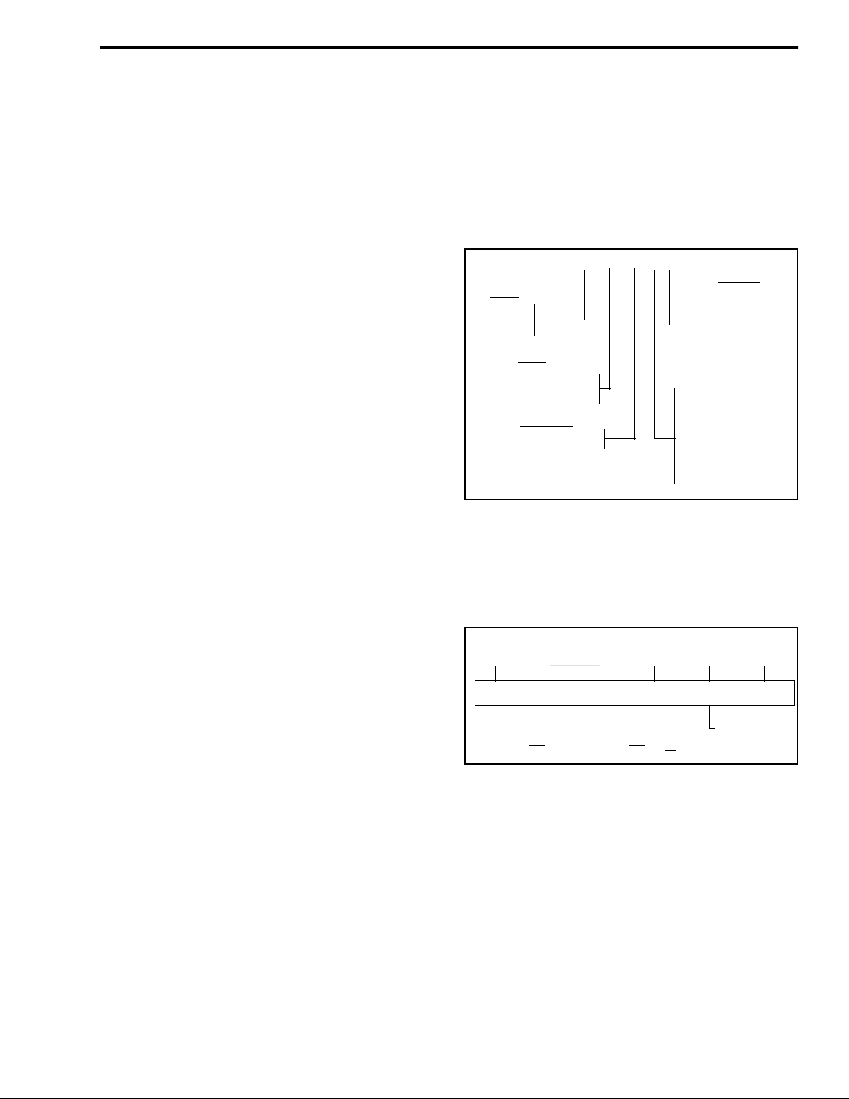
SECTION 2 INSTALLATION AND DISASSEMBLY
Optional Accessory Cable
P.N. 585-7600-027
DB-9 Female
INSTALLATION AND DISASSEMBLY
External Spkr Jack
UHF-Type
Ant Jack
10-Ft. Power Cable
Optional External Speaker
P.N. 250-0151-010
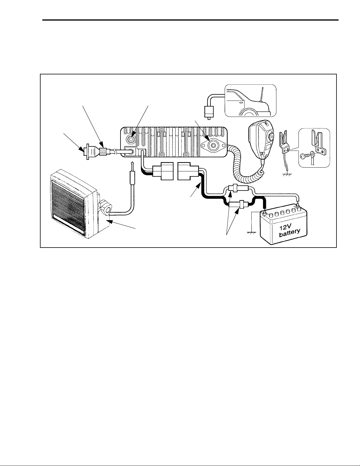
Figure 2-1 Installation Components
2.1 GENERAL
2.1.1 SCOPE OF INSTRUCTIONS
Since each installation is somewhat unique, the
following install at ion instructions are intended only as
a general guide to installing this transceiver.
2.1.2 PERFORMANCE TESTS
Although each transceiver is carefully tested at
the factory before shipment, it is good practice to verify proper operation before it is placed in service.
Important checks are receiver sensitivity and transmitter frequency, deviation, and power output.
Red (+)
Black (–)
20A Fuses
factory test channels and other test parameters when
they are shipped. The included labels should be
attached to the option keys to indicate the function.
2.1.4 POWER SOURCE
This transceiver must be connect ed to a nominal
12 VDC, negative ground vehicle electrical system
(negative battery terminal connected directly to the
chassis). If the vehicle has some other type of electrical system, a suitable voltage converter is required.
2.2 TRANSCEIVER INSTALLATION
2.2.1 SELECTING MOUNTING LOCATION
2.1.3 TRANSCEIVER PROGRAMMING
The transceiver needs t o be pr ogrammed be fore i t
is placed in service. Programming instructions are
located in Section 4. Transceivers normally contain
This transceiver is designed for mounting in a
location within convenient reach of the operator such
as the dash, console, or floor. Since the mounting location can affect safe operation of the vehicle, observe
the following precautions:
November 1998
2-1
Part No. 001-7600-001
Page 13

INSTALLATION AND DISASSEMBLY
Figure 2-2 Mounting Bracket Installation
WARNING
•
Do not mount the transceive r where it may int erfere with the operation of vehicle controls.
•
Do not mount the t ransceiver whe re the use r cannot easily reach the controls and view the
display.
•
Do not mount the t ransceiver where it may cause
additional injury in case of an accident.
•
Air bags inflate with great force. Therefore, do
not mount this transceiver in the deployment
area of an air bag. In addition, do not place other
objects in the deployment area or other locations
where they could unintentionally move into the
deployment area.
2.2.2 INSTALLING MOUNTING BRACKET
2.2.3 INSTALLING MICROPHONE HANGER
Install the included microphone hanger in a convenient location. For proper operation of functions
such as monitoring and scanning, the hanger may need
to be connected to chassis ground. If required, ground
the hanger using the included grounding wire.
2.3 POWER CABLE INSTALLATION
2.3.1 GENERAL
It is recommended that both wires of the power
cable be connected directly to the vehicle battery. Connection of either wire to other points m ay result in
increased interference from the vehicle’s electrical
system. If noise is sti ll a prob lem, t ry inst alli ng a noise
filter.
Check the area behind the intended mounting
location for wiring, brake and gas lines, or other components that could be damaged when the mounting
screws are installed. Th en install the b racket and tra nsceiver as shown in Figure 2-2. Both standard and selftapping screws are included for installing the bracket.
November 1998
Part No. 001-7600-001
2.3.2 CABLE INSTALLATION
1. Before starting power cable installation, it is good
practice to remove the negative cable from the battery to prevent damage from accidental short
circuits.
2-2
Page 14
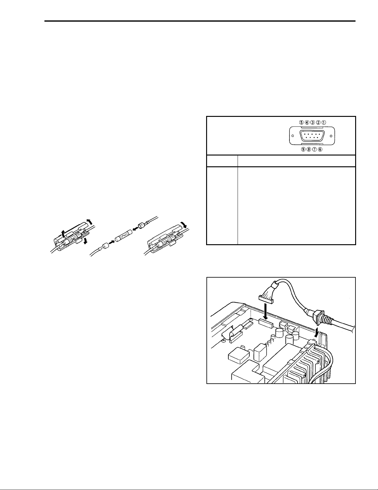
INSTALLATION AND DISASSEMBLY
DB-9 Female Connecto r
Outside View
2. Route the red and black wires from the transceiver
to the batte ry. Connect the red wire to the positive
(+) terminal and the black wire to the negative (–)
terminal.
3. Plug the cable into the pigtai l coming from the transceiver and reconnect the negative battery cable.
4. Install the antenna according to the manufacturer’s
instructions. The transceiver has a standard UHF
connector. Check VSWR. Reflected power should
be less than 4% of forward power (VSWR less than
1.5 to 1).
2.3.3 POWER CABLE FUSES
Each power cable wire is protected by a 20ampere fuse. Thes e fuse s are inspec te d and ch anged a s
shown below. If a fuse blows, locate the cause if possible and replace it with one of the same rating.
input that can be used to control the backlight (see
Section 3.3.9). This cable is installed as shown in
Figure 2-3.
This cable has a standa rd DB-9 female connector
for interfac ing to external equipment. The pin numbering and functions are as follows:
DB-9 Pin Function
1 LCD backlight control in
2AF out
3 Detected AF out
4 Modulati on in
5 PTT control in
6 Horn drive control out
7 AF ground
8 Detected AF ground
9 Modulati on ground
Changing 20-Ampere Power Cable Fuses
2.4 USING AN EXTERNAL SPEAKER
An external speaker can be plugged into the
external speaker jack on the back of the transceiver.
This speaker should have an impedance of 4-8 ohms
and a power handling capability of at least 3.5 watts.
The internal speaker is a utomatically disabled when a
speaker is plugged into this jack. The external speaker
jack is a standard 1/8-inch, two-conductor phone jack.
2.5 ACCESSORY CABLE INST ALLATION
Optional Accessory Cable, Part No. 585-7600027, can be used for connecting accessories such a
horn alert or modem to the transceiver. It also has an
Figure 2-3 Accessory Cable Installation
2-3
November 1998
Part No. 001-7600-001
Page 15
INSTALLATION AND DISASSEMBLY
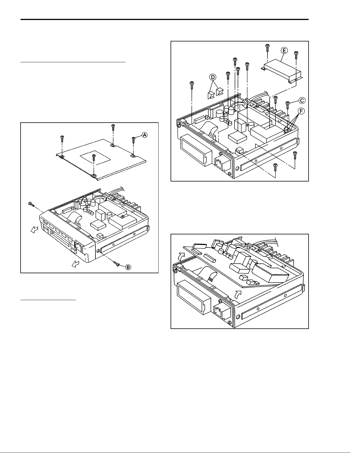
2.6 TRANSCEIVER DISASSEMBLY
Removing Bottom Cover and Front Panel
1. Remove the bottom cover b y removi ng four sc rews
(A) as shown in Figure 2-4.
2. Remove the front panel by removing two screws
(B).
Figure 2-4 Cover and Front Panel Removal
Removing PC Board
3. Remove ten screws (C) a nd t wo c li ps (D) as shown
in Figure 2-5.
4. Remove shield (E).
5. Unsolder the antenna connector at three points (F).
Figure 2-5 PC Board Screws
Figure 2-6 Removing PC Board
6. Lift the front of t he PC bo ard assembl y as shown in
Figure 2-6 and pull it out.
November 1998
Part No. 001-7600-001
2-4
Page 16
INSTALLATION AND DISASSEMBLY
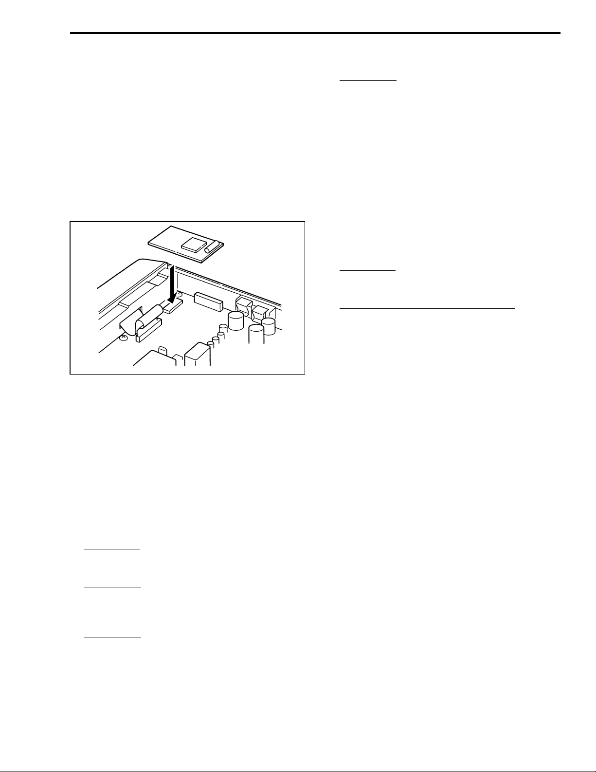
2.7 2-T ONE/5-TONE MODULE INSTALLA TION
2.7.1 INSTALLATION PROCEDURE
1. Turn power off and disconnect the power cable.
2. Remove the bottom cover by removing the four
screws (A) shown in Figure 2-5.
3. Install the module as shown in Figure 2-7. The
included foam pad is not used with this transceiver.
Screen Menu
program an option key or the microph one hanger
for the monitor function s o that the decoder can
be re-activ ated when the call is complete (see
Table 4-2).
2.7.3 5-TONE PROGRAMMING
Program the transceiver for operation with a fivetone module as described in Section 4. Screens that
need to be programmed with five-tone decoder information are as follows. Refer to on-line help for information on parameters in these screens (press F1 wit h
parameter selected).
Model Menu
Section 4.4.6).
Select the following in the Screen Menu:
•
“Rx Code CH” and program the information in
the screen (see Section 4.5.2).
- Select “Key & Displa y Assign” and
- “PMR” must be selected (see
Figure 2-7 2/5-Tone Module Installation
2.7.2 2-TONE PROGRAMMING
Program the transceiver for operation with a twotone decoder as described in Section 4. Screens that
need to be programmed with two-tone decoder information are as follows. Refer to on-line help for more
information on parameters in these screens (press F1
with parameter selected).
Model Menu
Section 4.4.6).
Screen Menu
program the information in the screen (see
Table 4-6).
Screen Menu
gram the information under “2Tone Dec” for
each channel on which the decoder wil l be use d
(see Table 4-1).
- “LMR” must be selected (see
- Select “2Tone Code CH” and
- Select “Memory Channel” and pro-
•
“Tx Code CH” and program the information in
the screen (see Section 4.5.2).
•
“User Tone” and program the info rmatio n i n the
screen (see Section 4.5.2).
•
“Memory CH” and program the parameters in
this screen that are related to 5-tone operation on
the channel (see Fi gure 4-2).
NOTE: If performing the deviation adjustment in
the next section, the long tone must be turned on in
RPT/STN/ID on the Memory Channel screen.
•
“Key & Display Assign” and program Tx Code
and Call switches for use in transmitting 5-tone
codes.
Setting 5-Tone Deviation
The only adjustment on the 2/5-tone module is a
potentiometer for setting the transmit tone deviation
for 5-tone operation. This control is factory preset and
should not require readjustment in the field. However,
if adjustment is required, proceed as follows:
2-5
November 1998
Part No. 001-7600-001
Page 17

INSTALLATION AND DISASSEMBLY
1. Monitor the transmi t si gnal wi th a communications
monitor. Set it for HPF = Off, LPF = 20 kHz, Deemphasis = Off, and Level = (P-P)/2.
2. Select a channel near the ce nter of the band and turn
a long tone on (see precedi ng “NOTE”) by pressin g
the appropriate front panel key.
3. Adjust potentiometer R18 (DEV) on the module for
the following deviation:
25 kHz Channel Spacing - ±3.5 kHz
20 kHz Channel Spacing - ±2.8 kHz
12.5 kHz Channel Spacing - ±1.7 kHz
4. Check channels on each end of the operating band to
make sure deviation is within the following
limits. If not, repeat preceding adjustment.
25 kHz Channel Spacing - ±3.0 to 5.0 kHz
20 kHz Channel Spacing - ± 2.4 to 4.0 kHz
12.5 kHz Channel Spacing - ±1.5 to 2.5 kHz
NOTE: It is recommended that scanning not be used
with these options because in may cause part or all of
the tone burst to be missed.
November 1998
Part No. 001-7600-001
2-6
Page 18
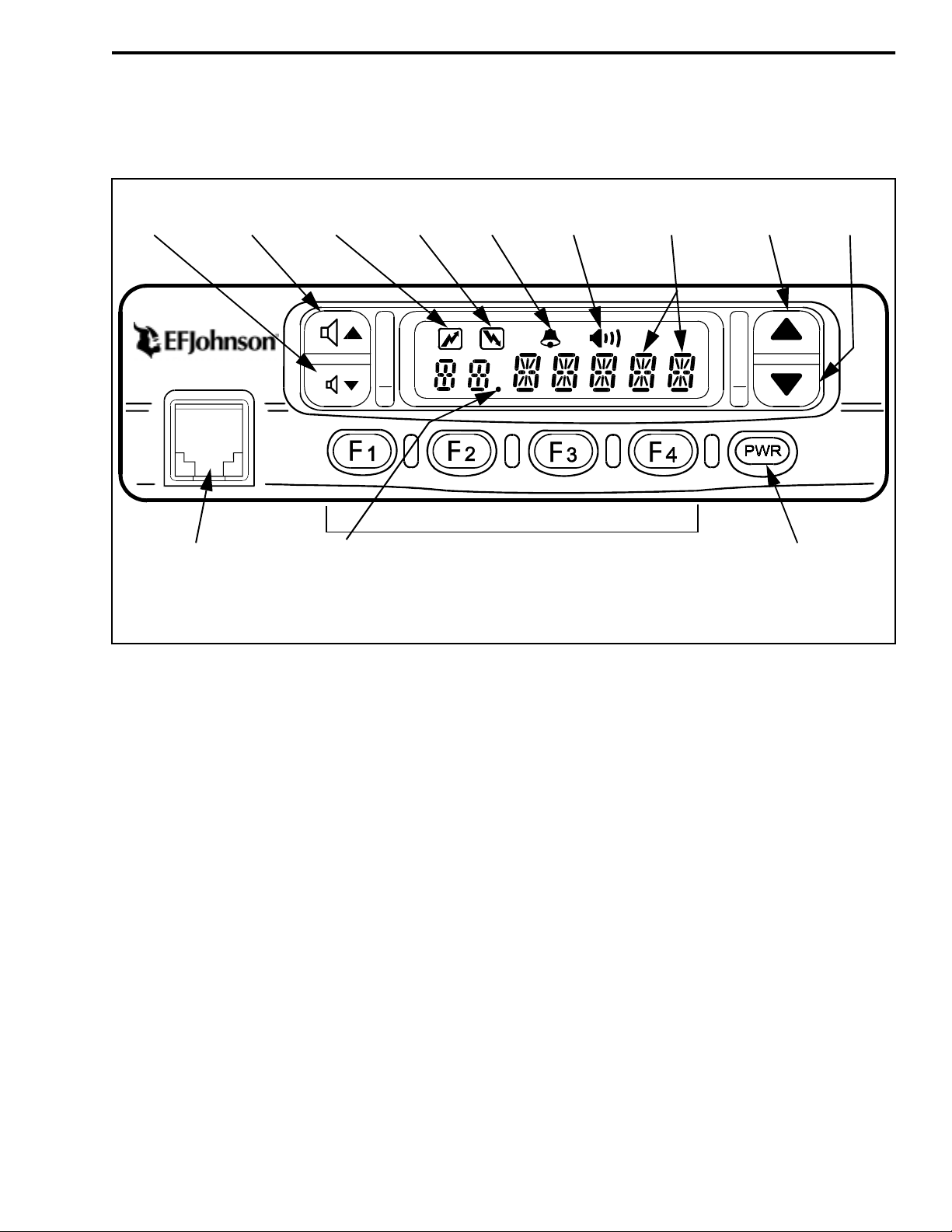
SECTION 3 OPERATION
OPERATION
Volume
Down
VolumeUpTransmit
Microphone
Connector
Busy
Indicator
Scan List
Indicator
* The Channel Up/Down switches can also be programmed for other functions.
Indicator
Programmable Option Switches
Bell
Indicator
Monitor
Indicator
Alphanumeric
Display
Channel
Up*
Channel
Down*
Power
Switch
Figure 3-1 7600 Front Panel
3.1 FEATURES
•
Up to 32 channels programmable
•
Multi-tone (CTCSS) and/or Mul ti-code (CDCSS)
Call Guard® squelch programmable
•
VHF and UHF, wideband and narrowband models
available
•
Up to 45 watts VHF and 35 watts UHF transmitter
power output
•
Seven-character alphanumeric display with backlight
•
Six programmable option ke ys
•
Busy indicator
•
Normal and priority scan to ensure that calls are not
missed
•
Up to five different user programmable scan lists
selectable
•
Bank select available (up to two banks with sixte en
channels each)
•
User selectable power output available
•
DTMF microphone optional
•
2-tone/5-tone signaling optional
NOTE: Some of the preceding features are available
only if programmed.
3-1
November 1998
Part No. 001-7600-001
Page 19
OPERATION
3.2 CONTROLS AND DISPLAY
3.2.1 FRONT PANEL CONTROLS
Power Switch (
- Press this switch to turn power
)
on and press and hold it to turn power off. The transceiver may be progr ammed so th at a passwor d must be
entered to allow operation. Refer to Section 3.3.2 for
more information.
Volume Up/Down Keys ( ) - Adjust the volume level up or down in up to 32 steps. The minimum
selectable volume level can be set as desc ribed in
Section 3.3.3.
Up/Down Keys ( ) - These keys may be programmed to select the next higher or lower channel or
for other functio ns. Ref er to th e descri ption s in Sect ion
3.5 for more information.
Microphone Connector - Connection point for the
microphone. Do not connect microphones other than
standard microphone P.N. 589-7600-020 and DTMF
microphone P.N. 589-7600-022 to this transce iver. The
pin assignments could be different and damage to the
microphone or transceiver may result.
F1/F2/F3/F4 - These keys ca n be programmed to control any of the fu nctions desc ribed in Section 3.5. Place
the applicable included label on the switch to indicate
its function.
Monitor Indicator ( ) - Indicates that the monitor
mode is enabled. This mode disables coded squelch
control so that all messages occurring on the channel
are heard. Refer Section 3.4.4 for more information.
Display - This seven-character display indicates the
selected channel, status information, and error conditions. If information in this display begins flashing, an
error condition is indicated. Two possible causes are a
defective antenna or a battery voltage below 8 VDC.
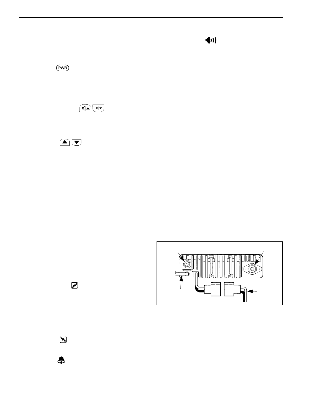
3.2.3 BACK PANEL
External Speaker Jack - Miniature phone jack for
connecting an optional 4-8 ohm external speaker. The
internal speaker is automatically disabled when a
speaker is p lugged into this jack.
Antenna Jack - UHF-type jack for connecting the
antenna.
DC Power Cable - Connects the transceiver to a nominal 12 VDC, negative ground vehicle power source.
Refer to Section 2-1 for more information.
Accessory Cable - This optional cable is used to connect accessories such as a horn alert and modem to the
transceiver. Refer to Section 2-1 for more information.
Ext Speaker
Jack
Antenna
Jack
3.2.2 DISPLAY
Transmit Indicator ( ) - Indicates that the transmitter is keyed or the 5-t one code is being sent (if appli cable). If this indicator is flashing, the internal
temperature is high and the tr ansmitter power output is
being cut back. Normal operation automatically
resumes when the tempera t ure returns to the normal
range.
Busy Indicator ( ) - Indicates the currently selected
channel is busy (see Section 3.4.4).
Bell Indicator ( ) - Appears or flashes when a
5-tone call is detected that the transceiver is
programmed to receive.
November 1998
Part No. 001-7600-001
Optional
Accessory Cable
Transceiver Back Panel
3.3 BASIC OPERATION
3.3.1 TURNING POWER ON AND OFF
When power is turned on by pressing the
POWER switch, a tone sounds and an opening message is displayed if programmed. The transceiver is
3-2
DC Power
Cable
Page 20
OPERATION
then ready to be used. To turn power off, press and
hold the POWER switch until power turns off.
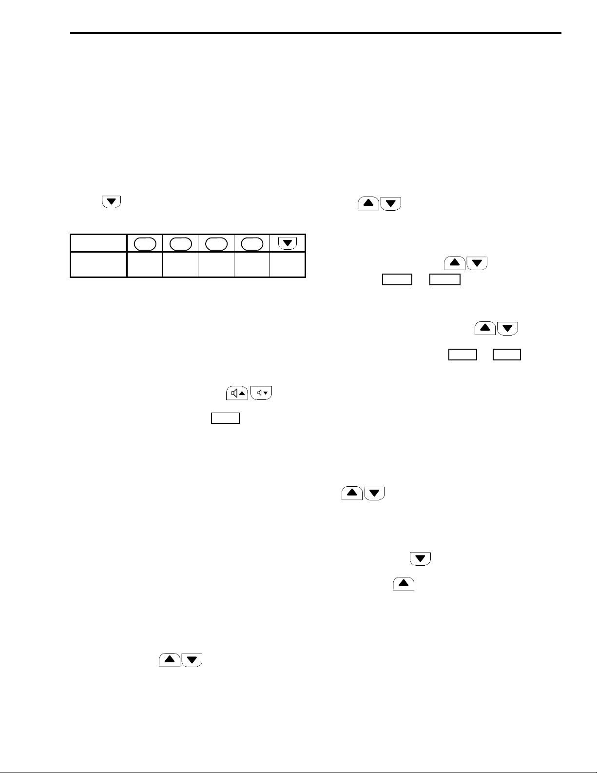
3.3.2 ENTERING A PASSWORD
The transceiver may be programmed so that a
password must be entered before the transceiver can
be used. When power is then turned on, “PWORD” is
displayed and the fo ur- di g it pas sc ode mus t be entered.
This code is entered using the F1-F4 and channel
down ( ) keys. The number entered by each key is
as follows. The numbers in a block are detected as the
Key
Number
Entered
F
0
5
F
1
1
6
F
2
2
7
F
3
4
3
8
4
9
same. For example, “1234” is the same as “6789”. If
the “PWORD” indication does not turn off after entering four digits, you may have entered an incorrect
number. Cycle transceiver power and try again.
3.3.3 VOLUME LEVEL ADJUSTMENT
and then again to return to the normal channel
display.
F1 - Minimum volume level (see Section 3.3.3)
F2 - Key beep on-off (see Section 3.5.4)
F3 - Backlight on-off (s ee Section 3.5.2
F4 - Squelch adjust (see desc ription whic h follows)
3. To return the F1-F4 keys to the programmed functions, turn transceiver power off and on again without pressed.
3.3.5 CHANNEL SELECTION
Channel Scrolling - If the keys are pro-
grammed as or keys, they can be
CH UP CH DN
pressed to scroll up or down through the programmed
channels.
Direct Selection - The F1-F4 and keys can
be programmed to directly select a specific channel.
These keys are then labeled to .
CH 1 CH 4
The volume can be adjusted in up to 32 steps by
pressing the volume up/down keys ( ). A
graph in the alpha numeric di splay indi cates t he current
volume level. If eq uipped wit h a option switch,
MONI
you may be able to press (or press and hold) that
switch to enable audio for use as a reference level.
The minimum selectable volume level can be set
by the power-on menu descri bed in Section 3.3.4.
Select this mode and then press F1 to display
“AFMIN”. Then press the volume up/down keys to
select the desired minimum level. The current level is
indicated by the bar graph, or receiver noise can be
enabled as described in Section 3.3.6.
3.3.4 POWER-ON MENU
The power-on menu is a special menu that can be
selected at power on to control various functions.
Proceed as follows:
1. Select the power-on menu by turning power on wit h
the up and down keys pressed.
2. The F1-F4 keys now control the following func-
tions. Press the switch once to select the function
3.3.6 ADJUSTING SQUELCH LEVEL
The squelch level is adjusted by programming or
selecting the power-on menu just described. Proceed
as follows to use the power-on menu:
1. Select a non-busy channel. Then select the power-
on menu by turning power on with t he up an d down
keys pressed.
2. Press the F4 option key to select the squelch adjust
mode indicated by “SQ xx”.
3. Press the down key until noise is heard from
the speaker (adjust the volume if necessary). Then
press the up key until the noise just mutes (the
“SQ xx” number indicates the relative squelch
level).
4. Reselect normal operation by turning p ower off a nd
on without the up and down keys pressed.
NOTE: If weak messages are not heard or unsquelching occurs when no messages are present, slight readjustment up or down may be required.
3-3
November 1998
Part No. 001-7600-001
Page 21

OPERATION
3.3.7 BANK SELECT
Two banks of up to 16 channels each can be programmed. Only the channels in the current bank are
then selectable. This would allow, for example, groups
of channels to be programmed for operation in different cities.
The key is pressed to switch between
BANK
banks, and the current bank is indicated br iefly in the
display as “BANK 1” or “BANK 2”. If bank select is
not used, a single block of up to 32 channels can be
programmed.
3.3.8 AUTOMATIC SCAN ENABLE
The transceiver can be programmed so that scanning is automatically enabled whenever power is
turned on or the microphone is placed on-hook. Refe r
to the scan description in Section 3.6 for more
information.
3.3.9 BACKLIGHT ON-OFF
The following backlight modes can be selected
by the option switch or by pressing F3 in the
LITE
power-on menu described in Section 3.3.4.
a microphone with a telephone keypad, or up to seven
telephone numbers also may be preprogrammed and
then selected by pressing the key (see descrip-
DTMF
tion in Section 3.5.7).
3.4.2 RECEIVING A CALL
1. Turn transcei ver power on and set the volume level
as described starting in Section 3.3.1.
2. Select or scan the channe l or channels on which you
want to receive the call. Refer to Section 3.6 for
more information on scanning.
3. When the message is received , take the micropho ne
off-hook and respond. Press the microphone pushto-talk (PTT) switch to talk and release it to listen.
4. When the conversation is finished, place the microphone back on-hook. The microphone hanger may
control features such as scanning and monitoring
that are described later.
3.4.3 PLACING A CALL
1. Turn transcei ver power on and set the volume level
as described starting with Section 3.3.1.
LI ON - On continuously
LI OF - Always off
LI AT - Controlled by the voltage applied to pin 1
of the DB9 connector on the optional accessory
cable (see “Light” in Table 4-2).
3.3.10 BEEP ON-OFF
The key beep which sounds when keys are
pressed can be enabled and disabled by pressing the
option switch or pressing F2 in the power-on
BEEP
menu described in Section 3.3.4. Either “BP ON” or
“BP OF” is displayed to indicate the current mode.
3.4 RECEIVING AND PLACING CALLS
3.4.1 INTRODUCTION
The two calls which can be placed and received
are mobile-to-mobile and telephone calls. With telephone calls, the tele phone number can be dialed using
2. Select the channel on which the call will be made as
described in Section 3.4.
3. Regulations require that the channel be monitored
before transmitting to make sure that it is not being
used by anyone else. If you were to transmit while
someone was talking, you would probably disrupt
their conversation. Refer to “Monitoring Before
Transmitting” description which follows for more
information.
4. If the channel is not busy, press the microph one P TT
switch to talk and release it to listen.
5. When the conversation is finished, place the microphone back on-hook.
3.4.4 MONITORING BEFORE TRANSMITTING
Use one of the following methods to monitor the
channel before transmitting a message:
November 1998
Part No. 001-7600-001
3-4
Page 22
OPERATION
•
Note if the busy indicator ( ) on the front panel
is being displayed. I f it is not, the channel i s not busy
and a message can be transmitted.
•
Taking the microphone off-hook disables coded
squelch control if it is programmed for the monitor
function. Take the microphone off-hook and the
indication should be displayed. If no messages are heard, the channel is not busy and a message
can be transmitted.
•
If the monitor ( ) option switch is pro-
MONI
grammed, pressing it disa bles coded squelch contro l
similar to taking the microphone off-hook. If no
messages are then h eard, the channel is not busy and
a message can be transmitte d. Press the switch again
to disable monitoring.
•
If the Transmit Disable On Bus y feature is pro grammed on the channel, t he trans mitte r is aut omatically disa bled if the channel is busy. This is
indicated by th e display flashing and a rapid beeping
when the PTT switch is pressed.
3.4.5 TIME-OUT TIMER
The time-out timer disables the transmitter if it is
keyed continuously for longer than the programmed
time. If the transmitter is disabled by this feature, the
transmit indicator ( ) turns off and the display
flashes and a beeping tone is produced until the PTT
switch is released.
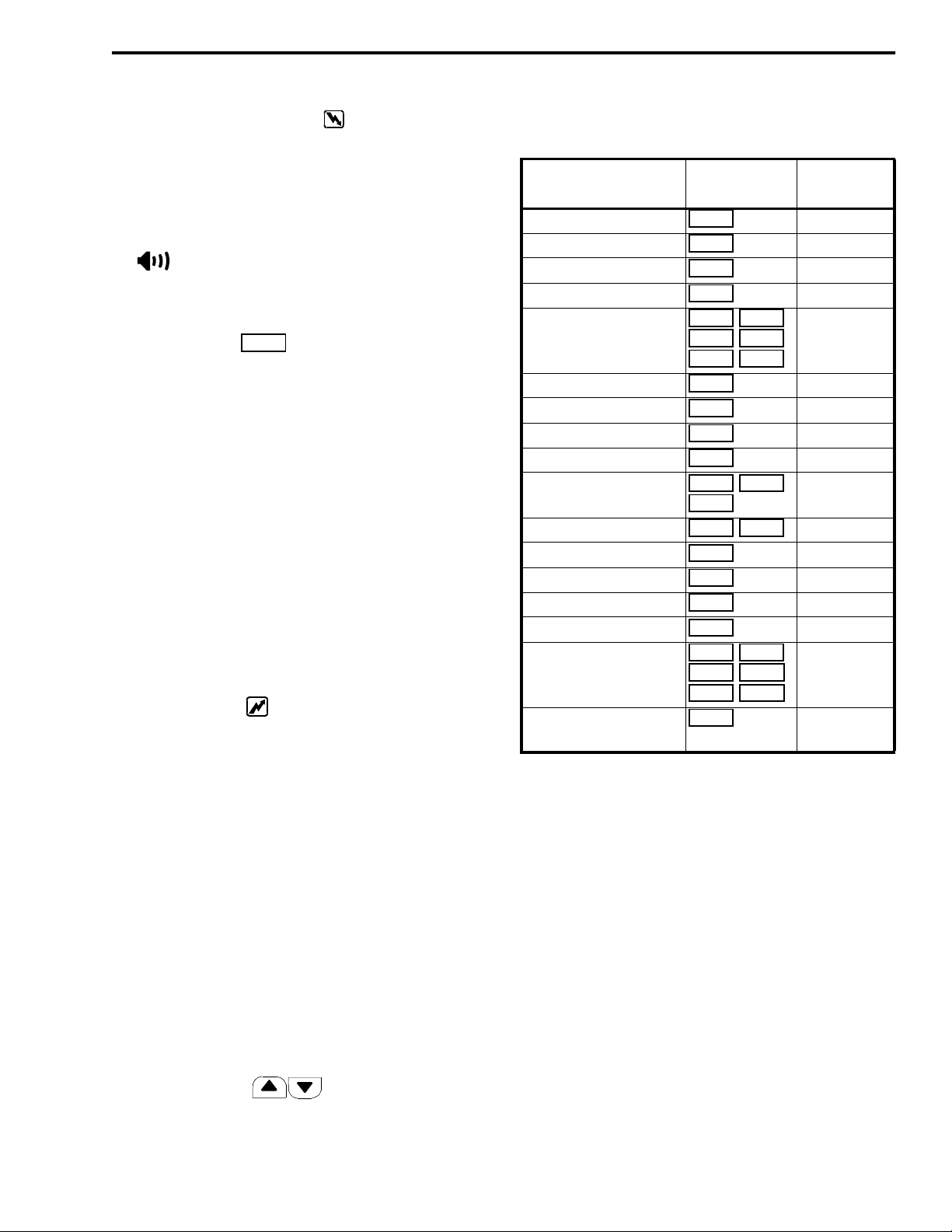
Table 3-1 Option Key Programmable
Functions
Function Key Label
Backlight On-Off 3.3.9
Bank Select 3.3.7
Beep on-off 3.3.10
Call Guard Tone Select 3.5.7
Channel Select
DTMF Number Select 3.5.7
Emergency Switch 3.5.8
Lock enable/disable 3.5.9
Monitor Mode Select 3.4.4
Output Power Select
Priority Channel Select 3.6.3
Receive Attenuate 3.5.13
Scan Select 3.6
Scan List Programming 3.6.2
T a lk -A rou nd Sel ect 3.5.16
2-Tone, 5-Tone Calling
Wide/Narrow Ban d
Select
LITE
BANK
BEEP
TONE
CH UP CH DN
CH 1 CH 2
CH 3 CH 4
DTMF
EMER
LOCK
MONI
HIGH LOW1
LOW2
PRI A PRI B
ATT
SCAN
TAG
TA
CALL CAL A
CAL B TX CH
CODE ID MR
W/N
Description
Section No.
3.3.5
3.5.11
3.5.18
3.5.19
One use of t his feature is to prevent a channel
from being kept busy for an extended period by an
accidentally keyed tr ansmitter. It can also prevent possible damage to the transceiver caused by transmitting
for an excessively long period.
There is also a penalt y timer that may be programmed to prevent further transmissions for the programmed time after the transmitter is disabled.
3.5 PROGRAMMABLE FUNCTIONS
3.5.1 INTRODUCTION
The F1-F4 and keys on the fr ont pa nel
can be programmed for the functions shown in
Table 3-1. A sheet of labels is included with the transceiver , and the applicabl e label should be placed on the
key to indicate its function. Refer to th e section listed
in the table for a descriptio n of the function.
3.5.2 BACKLIGHT ON-OFF
Refer to Section 3.3.9.
3.5.3 BANK SELECT
Refer to Section 3.3.7.
3.5.4 BEEP ON-OFF
Refer to Section 3.3.10.
November 1998
3-5
Part No. 001-7600-001
Page 23
OPERATION
HIGH
PRI A
PRI B
3.5.5 CALL GUARD TONE SELECT
If the transceiver has a key, the Call
TONE
Guard (CTCSS) tone can be selected. This allows calls
to be placed to different mobiles or groups of mobiles
and received on d ifferent groups than is normal f or the
channel. Proceed as follows:
1. Press the key and “TON--x” is displayed.
TONE
2. Press the channel up/down ( ) keys to
select the desired tone (“TON--1” to “TON--9”).
3. Press the key again to exit this mode. Calls
TONE
are then placed on the current channel and other
channels using the new code until it is changed.
4. To reselect the standard Call Guard squelch tone
programmed for the channel, select “TON--M”
using the same procedure.
3.5.6 CHANNEL SELECT
Refer to Section 3.3.5.
3.5.7 DTMF NUMBER SELECT
transmission begins, the call cannot be canceled. Programming determines the channel on which the call is
transmitted and also if it is transmitted once or repeatedly until a control code is received.
3.5.9 LOCK KEY
Press and hold the key to lock all pro-
grammable keys except and .
LOCK
CALL MONI EMER
Either “LK ON” or “LK OF” is displayed to indicate
the current condition. If a locked key is pressed, all
that happens is “LOCK” is displayed.
3.5.10 MONITOR MODE SELECT
Refer to Section 3.4.4.
3.5.11 OUTPUT POWER SELECT
The and keys can be used
LOW1 LOW2
to temporarily or permanently override the programmed power output for the channel. The programming of the “RF Power Selection” param eter in Table
4-2 determines operati on. Pressing the key once
selects the level on the key and pressing it again
selects the programmed level.
If the transceiver has a key, up to seven
DTMF
preprogrammed telephone numbers can be transmitted. Proceed as follows:
1. Press the key and the currently selected
DTMF
number is indicated as “DTMF x”.
2. Press the channel up/down keys ( ) to
select a different number.
3. To transmit the selected number on the current
channel, press and hold the key.
DTMF
NOTE: The DTMF 6 number is used for emergency
calls and the DTMF 7 number is used for automatic
logging. Therefore, if these features are used, the
number may not be available for regular calls.
3.5.8 EMERGENCY KEY
Press and hold the key to transmit an
EMER
emergency call. To cancel th is call before it is transmitted, press and hold thi s key agai n. Once emer ge ncy
3.5.12 PRIORITY CHANNEL SELECT
Pressing selects t he priority A channel
and pressing selects the priority B channel.
The key can also be programmed so that press-
PRI A
ing and holding the key makes the current channel the
priority A channel. Refer to Section 3.6.3 for more
information.
3.5.13 RECEIVE ATTENUATE
Pressing th e key turns receive signal
ATT
attenuation on and off. Either “AT ON” or “AT OF” is
displayed to indicate the current mode. The attenuator
can be turned on if nearby strong RF signals such as
commercial radio stations or pager transmitters are
causing distortion of the receive signal.
3.5.14 SCAN SELECT
Pressing th e key turns the channel scan
SCAN
feature on and off. Refer to Section 3.6 for more
information.
November 1998
Part No. 001-7600-001
3-6
Page 24
OPERATION
3.5.15 SCAN LIST PROGRAMMING
Pressing the key changes the scan list sta-
TAG
tus of the cu rrent channel. Refer to the scan list
description in Section 3.6.2 for more information.
3.5.16 TALK-AROUND SELECT
The talk-around mode causes transmissions to
occur on the receive frequency to permit dir ec t
mobile-to-mobile communication when a repeater is
being used. The talk-around mode is turned on and off
by pressing the key. Either “AR ON” or “AR
TA
OF” is briefly displayed to indicate the current mode.
Changing the channel or turning power off causes talkaround to revert to the off condition.
3.5.17 2-TONE CALLING FEATURES
If the optional 2-tone signaling option is used,
pressing the key transmits the 2-tone codes on
CALL
the selected channel or on a non-busy channel if
pressed while scanning.
3.5.18 5-TONE CALLING FEATURES
If the optional 5-to ne signa li ng opti on is us ed, the
following keys may be pr ogr ammed to control various
functions.
- Transmit the 5-tone call.
CALL CAL A CAL B
Depending on your signali ng system, cal l transmi ssion
may be necessary before you call another station. The
CAL A and CAL B keys may be programmed when
selective Individual/Group calls are used.
- Selects the 5-tone code to be transmitted. To
TX CH
change the contents of the station code, push and hold
this key and then press the keys.
- Selects th e transmit code directory.
CODE
- Recalls last five codes received. Press and
MR CH
hold to erase all codes. To scroll, pr ess .
3.5.19 WIDE/NARROW BAND SELECT
Pressing the key switches the receiver
W/N
between narrowband and wideband operation. The
display briefly indicates “WIDE” or “NARROW” to
indicate the current mode. Each channel can also be
programmed for wide or narrow band operation, and
this switch toggles that setting. However, the change is
only temporary because the programmed condition is
reselected if the c h an nel is changed or power is cycled.
3.6 CHANNEL SCAN
3.6.1 INTRODUCTION
The channel scan f eature monitors t he channe ls in
the current scan list. When a message is detected that
the transceiver is programmed to receive, scanning
stops and the message is received. Shortly after the
message is complete, scanning resum es (after the
resume timer counts down). The selected channel
changes to that of the call.
If the microphone is taken off-hook or the transmitter is keyed while scanning, scanning resumes
when the auto reset timer selected for the channel
counts down. Scanning does restart if this timer is disabled or if the Scan A key is programmed with poweron scan disabled (see Tables 4-2 and 4-5).
Scanning is turned on and off by the key.
SCAN
The transceiver also may be programmed so that scanning automatically turns on whenever power is turned
on or the microphone is placed on-hook. The microphone must be on-hook for scanning to occur.
The decimal point in the di splay flashes when the
scan mode is enabled. Then when scanning is actually
occurring, either the scan list identification (see next
section) or the ra pidly c ycling chan nel ide ntif icati on is
displayed as the channels are scanned. Programming
determines which occurs (see Table 4-5).
3.6.2 SCAN LISTS
Up to five scan lists can be selected by pressing
and holding the key until the scan list identifi-
SCAN
cation appears and then pressing the keys.
Press the key again to exit this mode (this also
SCAN
occurs automaticall y in ab out 30 secon ds) a nd again to
enable scanning (if desired).
3-7
November 1998
Part No. 001-7600-001
Page 25

OPERATION
PRI A
The scan lists are user programmable if the
key is available. Pressing this key changes the
TAG
status of the displayed channel in the current scan list
only. The display indicates “SC ON” if the channel
was just added to the scan list and “SC OF” if it was
just deleted. In addition, the sc an list sta tus is in dicat ed
by the decimal point in t he display. This indicator is on
when the displayed channel is scanned. The decimal
point flashes when scanning is occurring.
The scan list status of a channel can be changed
while scanning only when listening to a message on
the channel. The current status of all the lists is sto r ed
in memory. Therefore, the status of the various scan
lists does not change when power is turned off.
3.6.3 PRIORITY CHANNEL SAMPLING
Priority channel sampli ng en sur es that me ssa ges
on priority channels are not missed while listening to
messages on other channels. If priority sampling is
used, a priority A channel is designated by programming. If the key is available, pressing that key
selects the priority A channel. This key also may be
programme d so that if it is pressed and held, the priority A channel changes to the current channel.
Sampling of the priority A channel occurs only
when scanning is enabled. It does not occur while
transmitting. When the priority channel is sampled
while listening to a message on another channel, a
series of “ticks” are heard. These ticks are brief i nterruptions of the audio signal that occur while the transceiver changes channels to check the priority channel.
Another priority channe l also can be pr ogrammed
that can be quickly selected by the key. This
PRI B
channel is programmed only to allow quick selection
and is not sampled while listening to a non-priority
channel.
November 1998
Part No. 001-7600-001
3-8
Page 26
SECTION 4 PROGRAMMING
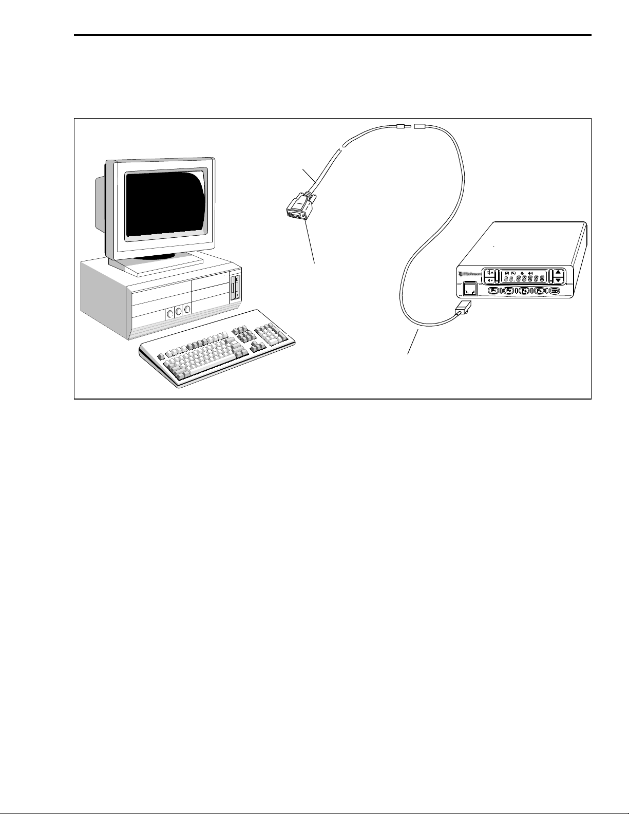
Programming Cable
(Includes Le vel Convert. Circuit)
P.N. 585-7500-031
Female DB9 Plug To Computer
PROGRAMMING
Figure 4-1 Programming Setup
4.1 GENERAL
4.1.1 PROGRAMMING SETUP
The following items are required to program this
transceiver. The part numbers of the programming
cable and software ar e shown in Table 1-1. A printer is
also recommended for making a hard copy record of
the information programm ed into the transceiver. The
programming setup is shown ab ove.
•
IBM® PC AT or PS/2 compatible computer with
one available serial port
•
MS-DOS® version 5.02 or higher or equivalent
•
E.F . J ohnson programmin g cable (inclu des require d
level converter circuit) and adapter cable
•
E.F. Johnson programming software
4.1.2 PROGRAMMING CABLES
Programming Cable, Part No. 585-7500 -03 1, and
Adapter Cable, Part No. 58 5-7600- 031, are r equire d to
Adapter Cable
P.N. 585-7600-031
connect the computer to the transceiver. The programming cable has a female DB9 connector which plugs
into the serial port of the computer. In this connector is
a level converter circuit which converts the RS-232
levels of the computer to the logic levels required by
the transce i ver. The other end of th e cable plugs into
the adapter cable which adapts the miniature phone
plug to the modular-styl e microphone conne ctor on the
transceiver. Turn transceiver power on after these
cables are connected.
4.1.3 PROGRAMMING SOFTWARE
The programming software is distributed on a
3-1/2” 1.44 M diskette. Th is disket te incl udes the mai n
executable program RP7600.EXE and several ancillary files it requires to run. These files total approximately 430k in size. Also included on this disk is the
ADJUST program used to tune the transceiver. This
program and other files it requires to run total about
180k in size and are located in a separate subdirectory
4-1
November 1998
Part No. 001-7600-001
Page 27
PROGRAMMING
on the disk called ADJ. The use of this program is
described in Section 5.
These are DOS programs, so Windows® 3.x, 95,
or NT are not required to run them. If the program
does not run properly in Windows, run it in the DOS
mode.
Before you use the program, the files on the diskette should be copied to your hard disk or a programming disk. Do not use the distribution disk for programming or transceiver tuning because it should be
kept as a backup in case something happens to the program on the working disk.
4.2 STARTING THE PROGRAM
Proceed as follows:
1. Start the computer in the DOS mode. If the pro gram
is not installed on a hard drive, insert th e programming disk in drive A.
•
The Space or backspace key toggle the setting.
•
Use the File menu to save the data and exit the
program.
4.4 MENU FLOW
4.4.1 INTRODUCTION
The menu bar along the top of the screen is used
to select the various menus that are used to program
this transc eiver. Press the ALT or ESC key to enable
this menu bar. Then to move horizontally to select a
menu, use the arrow (←
lighted letter in the title. Then to display the menu and
highlight the desire d item, use the arrow (↓ ↑) keys
and then press ENTER to select it. The following
describes each of the menus that can be selected.
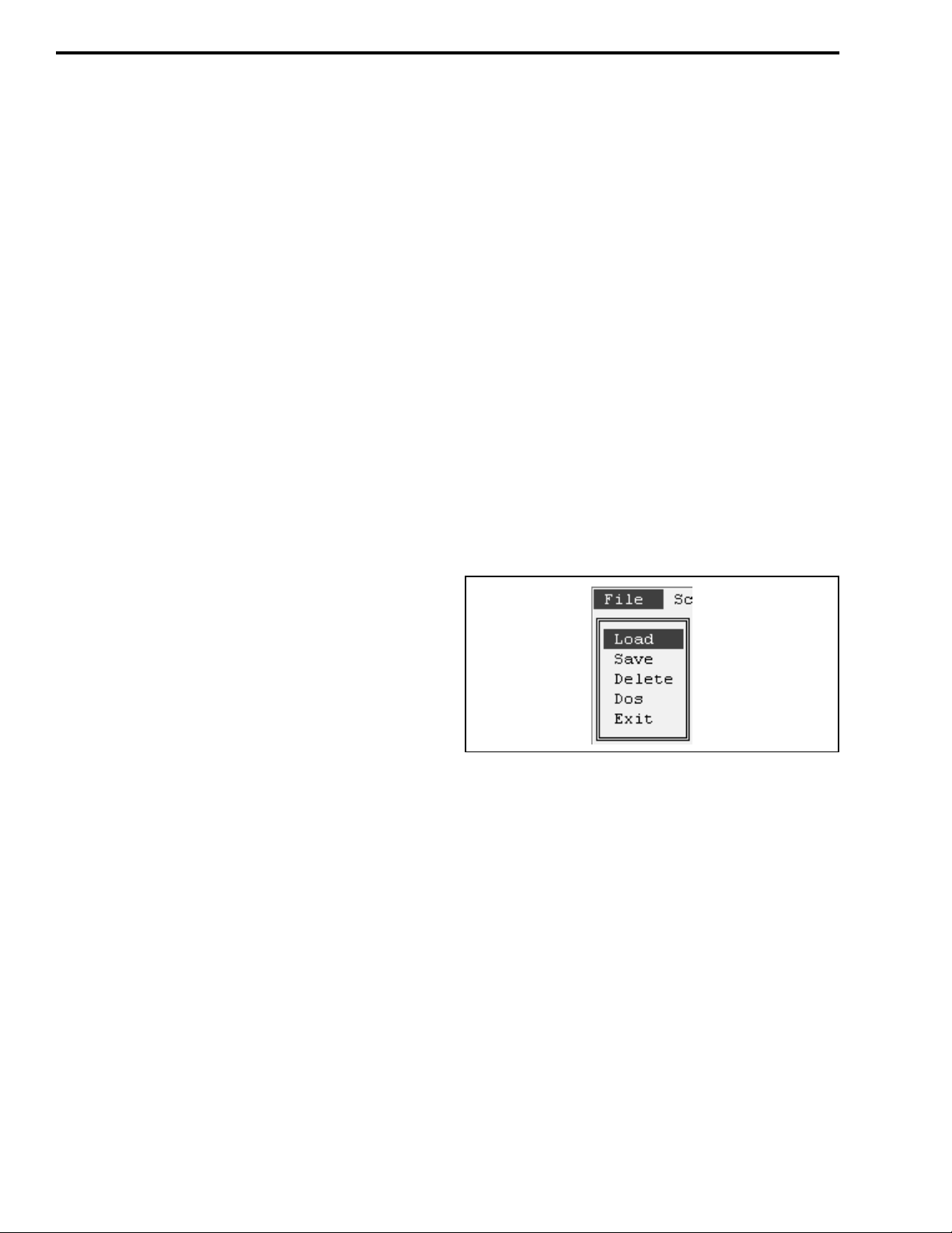
4.4.2 FILE MENU
→
) keys or type the high-
2. Make the directory of the program the cur rent dir ectory. Then start the program by typing RP7600
(Enter).
3. The Memory Channel screen described in Section
4.4.3 is then displayed. Set or modify the data as
desired. Make sur e to scroll r ight using the → key so
the right-most screen parameters can be
programmed.
4.3 SPECIAL KEYS AND FUNCTIONS
•
Information on the various parameters is available
in the form of help screen s. To display information
on the currently highlighted function or setting,
press F1.
•
Pressing ALT or ESC selects the menu on top or
returns to the previous screen.
•
↑ ↓ keys or highlighted character keys move the
cursor.
Load - Loads data from a previously saved data file.
To display the directory, press (Enter) again.
Save - Saves the current data to the specified file. The
extension “. ICF” is automatically added to the file
name.
Delete - Dele tes the current file.
Dos - Allows you to go to the DOS mode to perform a
function in DOS such as copying a file. To return to
the previous screen, type EXIT.
Exit - Quits the program and exits to DOS.
November 1998
Part No. 001-7600-001
4-2
Page 28
PROGRAMMING
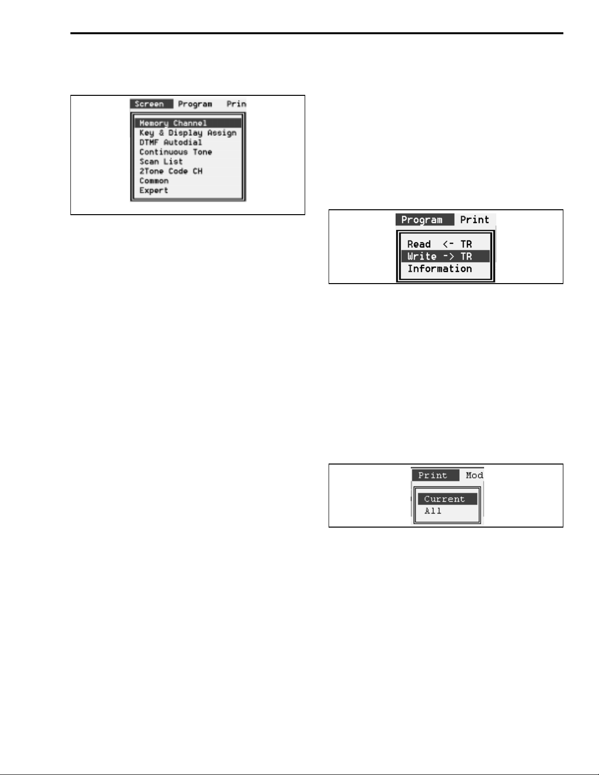
4.4.3 SCREEN MENU
LMR (U.S.) Format
NOTE: The Screen menu for PMR (European) models
is slightly different than the LMR version shown
above. Refer to Section 4.5 for more information on
PMR models.
Memory Channel - Displays the screen shown in
Table 4-1 which is used to program channel parameters such as frequency, Call Guard (CT CSS/DCTS)
coding, and power output. The screen in Table 4-1 is
for LMR models; refer to Section 4.5 for information
on the PMR version.
Key and Display Assign - Displays the screen shown
in Table 4-2 which assigns functions to the
programmable keys.
Common - Displays the screen shown in Table 4-7
which programs miscellaneous information such as
various timer settings.
Expert - Displays the screen shown in Table 4-8
which programs various timers and other information.
Normally, the default value in this screen should not
be changed.
4.4.4 PROGRAM MENU
Read ← TR - Reads the data programmed in the connected transceiver.
Write → TR - Programs the connected transceiver
with the current data.
Information - Displays information on the connected
transceiver such as the model, revision, and the “Program Comment” programmed in the Common screen
(see Table 4-7).
DTMF Autodial - Displays the scr een shown in Table
4-3 which programs five DTMF code channels (prestored telephone or other numbers). Up to 24 characters can be programmed in each location.
Continuous Tone - Displays the screen shown in
Table 4-4 which programs nine user selectable Call
Guard (CTCSS) tones.
Scan List - Displays the screen shown in Table 4-5
which programs various parameters for each scan list.
2-Tone Code Channel - Displays the screen s hown in
T able 4-6 which programs transcei ver oper ation wi th a
2-tone option. The optional 2/5-Tone Decoder Kit,
Part No. 585-7500-026, is required to use the 2-tone
function. This screen is displayed with LMR models
only (see Section 4.4.6).
4.4.5 PRINT MENU
Current - Prints the currently displayed data.
All - Prints all data for the selected file.
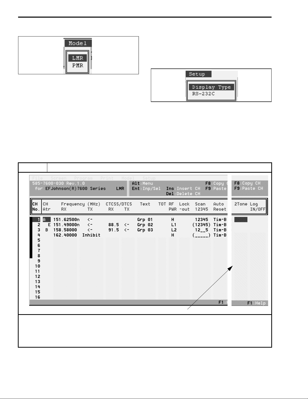
4.4.6 MODEL MENU
LMR - Selects LM R (U.S.A.) models. Selecting this
model displays unique parameters in various screens
for programming a 2-tone option. The differences are
4-3
November 1998
Part No. 001-7600-001
Page 29
PROGRAMMING
in the Screen menu (see Section 4.4.3), Memory
Channel screen (see Table 4-1), and DTMF Autodial
screen (see Table 4-3).
Refer to Section 4.5 for mo re information on PMR
models.
4.4.7 SETUP MENU
PMR - Selects PMR (European) models. Selecting
this model displays unique parameters for program-
Display Type - Select the color or monochrome 1 or 2
display modes.
ming a 5-tone option. As with the LMR selection,
unique parameters are displayed in the Screen menu
and Memory Channel an d DTMF Autodial screens.
RS-232C - Selects the computer seri al p ort b ein g used
to connect the computer to the transceiver.
Table 4-1 Memory Channel Screen Description (LMR Models)
Parameter Description
NOTE: To display th is part of the screen, scroll over using the → arrow key
.
Bank Select
Up to 32 channels or two banks of 16 channels can be programmed. To program the channels as two banks, first
program the “MR-CH Bank/Free” parameter in the Key and Display Assign screen for “Bank” as described in Table 4-2. In
addition, a “Bank” option switch must be programmed in this screen to select banks. To switch between banks when
programming channels, press the PgUp/PgDn keys.
November 1998
Part No. 001-7600-001
4-4
Page 30

Table 4-1 Memory Channel Screen Description (LMR Models) (Continued)
Parameter Description
Ch Atr
(Channel
Attribute)
Frequency
(Rx/Tx)
CTCSS/
DTCS
(Rx/Tx)
Press (Enter) to display the menu which selects one of the following choices:
A: Prio rit y A - The chan nel is selected when the Prio A key is pressed, and it is monitored during priority scan.
In addition, the microphone hanger can be programmed so that this channel is automatically selected whenever an off-hook condition occurs (see Table 4-2).
B: Priority B - The channel is quick selected when the Prio B key is p ressed. It is not monitored during priority
scan.
E: Emergency Channel - Transmission occurs on the channel when the Emergency s witch is pressed.
Emergency Off - Deletes the emergen cy designation o n curren t channel if applicable. If n o emerg ency chan nel
is designated, transmission occurs on the currently selected channel.
SmarTrunk II™ On/Off - Toggles the SmarTrunk function on and off on the bank. This function is not
available with this transceiver.
Channel Insert - Inserts a blank channel by pushing the other channel information down one line.
Channel Delete - Deletes the programming information on the current line and moves the channel information
below it up one line.
Return - Exits the menu and returns to the main screen.
Enter the desired frequency for the channel. Enter a frequency within the frequency range of the transceiver:
VHF = 136-155 or 146-174 MHz, UHF = 400-430, 450-470, 470-490, or 488-512 MHz. Channel steps in multiples of 5.0, 6.25, or 7.5 kHz only. If no receive frequency is entered, no other data can be programmed on the
line. Other special functions associated with frequency are as follows:
Rx Fre q - Press the backspace key to toggle between wide and narrowband. Nar rowban d is in dicated b y “n” to
the right of the frequency. Press the spacebar to toggle receive inhibit on and off indicated by “i” to the left
of the frequency. This limits the channel to priority or emergency use only (it is not available as a regular
channel).
Tx Freq - To enter the same frequency as the receive frequency, enter nothing or “=”. The “←” symbol means
same as receive frequency. Enter a space to disable transmitting on the channel (“Inhibit” is then displayed).
F8 and F9 can be used to cut and paste frequencies. Press (Enter) when the desired frequency has been
entered.
Enters the receive and transmit tone (CTCSS) Call Guard® frequency or digital (DTCS) Call Guar d code. Press
(Enter) to display the tone selection table. Select a tone by scrolling to it and pressing (Enter). Press the spacebar or backspace key to increase or decrease the entered frequency. The “←” symbol means same as receive
code.
PROGRAMMING
The length of the CTCSS reverse burst can be set by the “CTCSS Reverse Burst” parameter on the Common
Screen (see Table 4-7). A non-standard CTCSS tone from 60.1 to 300.1 Hz can be specified on the Expert
screen and then selected by “USER”. If a CTCSS tone is selected by the TONE option switch, it overrides the
channel programming until “TON--M” is reselected.
Digital codes must
sure to enter the tone decimal point or the number is interpreted as a digital code. To toggle the polarity of digital codes, press the spacebar or backspace key. The N or I indicates Normal or Inverted polarity. In
addition, the polarity of digital Call Guard signaling for all channels is set on the Expert screen.
Text P rograms the 7-character alpha tag that is displayed when a channel is selected. If no text is programmed, the
channel number is displayed as CH-xx. Allowable characters are A-Z (upper or lower case), 0-9, ’ * , + $ ’ ( ) –
/ < = > ? @ [ \ ] _ { | } ~. However, some characters, especially lower case letters, may be difficu lt to see. The tx
up arrow is displayed by “:” , and the rx down arrow by “;”. Special characters may be programmed in the
Expert screen (see Table 4-8) and used for the positions 3-7 only (positions 1 and 2 can display only regular
characters). To enter a special character, press PgUp/PgDn to scroll through and select characters A-P.
TOT
(Time-Out
Timer)
Smartrunk II™ is a trademark of Smartrunk Systems Inc.
Disables the transmitter on that channel if it is keyed continuously for longer than the programmed ti me. The
times for this timer and other related functions are programmed in the Common Screen (see Table 4-7).
always be entered directly (there is no table) and tone frequencies can be entered dir ectly. Be
November 1998
4-5
Part No. 001-7600-001
Page 31

PROGRAMMING
Table 4-1 Memory Channel Screen Description (LMR Models) (Continued)
Parameter Description
RF PWR Programs the RF power output for the channel (High, Low1, Low2). This setting can be temporarily or perma-
nently overridden by the HIGH, LOW1, or LOW2 power option switch if it is programmed (see Table 4-2).
Lockout Transmit Disable On Busy. The following conditions can be programmed:
Off - No restrictions; the transmitter can be keyed even while receiving a signal.
Busy - Transmitting is inhibited if the channel is busy (carrier present).
Repeater 1 - Transmission is permitted only when (1) receiving a signal on the programmed Call Guard tone or
code (CTCSS/ DCTS) or (2) when no carrier is being detected.
Repeater 2 - T rans mission is permitted when (1) receiving any Ca ll Guard ton e o r co de ( CTCSS/DCTS) or (2)
when no carrier is being detected.
NOTE: If an attempt is made to transmit in a lockout condition, tra nsm itting is inhibited for the “Lockout
Penalty Time” programmed on Common screen (see Table 4-7).
Scan Assigns the channel to up to five scan lists and also programs if the scan list status can be changed by the scan
list programming key (TAG). Press the spacebar to enter or delete all lists or press 1-5 to toggle the status of a
list. Press the backspace key to toggle the inhibit status. Scan list programming is inhib ited when parentheses
are displayed around the numbers (or underline characters).
Auto Reset If PWR ON Scan is enabled in the Scan screen (see Table 4-5), this selects the time delay before scanning
resumes after a call is complete (the signal disappears) or a key is pressed. Either Timer A or Timer B can be
selected. These timers are programmed in the Common Screen (see Table 4-7). Auto reset can be turn ed off by
setting the timer to “Off” (0).
2-Tone Enables 2-tone operation on the channel and specifies the 2-tone code used. The 2-tone codes are programmed
in the 2-Tone Code Ch screen (see Table 4-6). This requires the optional 2/5-tone module.
Log On/Off Specifies if the DTMF ID code is transmitted when the PTT switch is pressed and releas ed. Th e DTMF code is
specified on the Log/ID line of the DTMF Autodial screen (Table 4-3). In the Common screen, if “TOT Timer
ID Out” is “Yes”, this ID is also transmitted just before the transmitter is disabled by the time-out timer. The
following conditions can be programmed:
OFF (blank) - No ID code is transmitted.
Log In - The ID code is transmitted when the PTT switch is pressed.
Log Off - The ID code is transmitted when the PTT switch is r eleased.
Both - The ID code is transmitted when the PTT switch is pressed and again when it is released.
November 1998
Part No. 001-7600-001
4-6
Page 32

PROGRAMMING
Table 4-2 Key and Display Assign Screen Description
KEY ASSIGN PARAMETERS
The and F1-F4 option keys can be programmed for the following functions. Press the (Enter) key and then
PgUp/PgDn to display and then select the desired function.
Parameter
Null --- No function (key disabled).
CH Up
CH Down
MR-CH 1
MR-CH 2
MR-CH 3
MR-CH 4
Bank BANK Toggles the current bank between Bank 1 and Bank 2. This key can be programmed only if the “MR-
Scan A
Scan B
Start/Stop
Scan Add/
Delete
Prio A
Prio A (Re)
Prio B
Moni
(Audi)
Key
Label
CH UP
CH DN
CH 1
CH 2
CH 3
CH 4
SCAN Pressing this key toggles scanning on and off. In addition, pressing and holding the key enables the
TAG Scan list programming key. Pressing this key changes the scan list status of the current channel in the
PRI A
PRI A
PRI B
MONI Toggles the monitor mode on and off. This mode deactivates the Call Guard (CTCSS/DTCSS) or
Scroll up or down through the programmed channels. Holding the key down causes the function to
repeat.
Directly selects Channels 1, 2, 3, or 4, respectively.
CH Bank/Free” parameter in this screen is programmed “Bank”.
scan list select mode. The current scan list is indicated, and it is changed by pressing the up/down
keys. Either the Scan A or Scan B mode or both can be programmed. Operation is as follows:
Power-On Scan “Off” (see Table 4-5) - It starts and stops scanning with no auto restart. If the transmitter is keyed during scanning, the scan mode is exited.
Power-On Scan “On” - It stops scanning only until the Auto Reset Timer expires (see Table 4-7). If
the transmitter is keyed during scanning, scan automatically resume s when the Auto Reset Timer
expires.
Power-On Scan “Off” or “On” - It starts and stops scanning with auto restart. If the transmitter is
keyed during scanning, scan automatically resumes when the Auto Reset Timer expires.
current scan list (see Section 3.6.2).
Pressing a Prio A key selects the Priority A channel, and pressing a Prio B key selects the Priority B
channel. Pressing a Prio A (Rewrite) key also selects the Priority A channel. In addition, if it is held, the
current channel is made the Priority A channel. Priority channel sampling is programmed in the Scan
List screen (see T able 4-5).
2-tone mute functions (see Section 3.4.4). Pressing and hold ing this key uns quelches the receiver for as
long as it is held.
Description
Scan A
Scan B
4-7
November 1998
Part No. 001-7600-001
Page 33

PROGRAMMING
Table 4-2 Key and Display Assign Screen Description (Cont inued)
Parameter
RF ATT ATT
Lock LOCK
Beep BEEP
Light LITE
Bank Up
High
Low 1
Low 2
C. Tone
CH Ent
Talk
Around
Wide/
Narrow
DTMF
Autodial
Emergency
Single
Repeat
OPTx Out
OPTx
Mom Out
Call CALL
Call A/B CALL
Tx Code/
CH Up/Dn
ID MR
Select
Trunking
Group
Switch
Hanger
Action
Beep On/
Off
Key
Label
HIGH
LOW1
LOW2
TONE
TA
W/N
DTMF
EMER
OPT1
OPT2
OPT3
TX CH
ID MR
GRP
Any or none of the following hanger functions can be programmed:
Monitor Scan Prio A -
Enables or disables the ke y p ress bee p. Th is programming can be overridden by the power-on menu (see S ectio n
3.3.4) or B EEP key (see S ection 3.3.10).
Description
Toggles the receive attenuate function on and off (see Section 3.5.13).
Locks/unlocks all programmable keys except CALL, MONI, and EMER to prevent them from being
accidentally pressed (see Section 3.5.9).
Toggles the key beep function on and off (see Section 3.3.10).
Turns the LCD backlight on and off (see Section 3.3.9).
Selects the other bank of sixteen channels if applicable.
Changes the power output for the current channel to the level programmed of the key. Pressing the key
again reselects the preprogrammed power level for the channel. The change may be temporary or permanent for that channel depending on the programming of the “RF PWR Selection” parameter later in
this screen (see description which follows).
(Continuous Tone Memory Channel) This key selects the continuous tone mode which allows the Call
Guard (CTCSS) tone to be selected from the front panel (see Section 3.5.5). These tones are programmed by the Continuous Tone screen described in Table 4-4.
Toggles the talk-around mode on and off (see Section 3.5.16).
Tem porarily toggles between the wide and narrow band modes (see Section 3.5.19). When th e channe l
is changed or power is cycled, the wide/narrow mode programmed for the chann el frequ ency s pecified
in the memory Channel screen is again selected.
Pressing this key enables the DTMF autodial mode. After pressing this key, the number to be dialed is
selected by the up/down keys. Then press and hold this key to transmit the number (see Section 3.5.7). The available DTMF numbers are programmed by the DTMF Autodial screen described in
Table 4-3.
Pressing this key transmits an emergency call. If “Single” is programmed, it is transmitted only once; if
“Repeat” is programmed, it is transmitted repeatedly with LMR mod els, or until the pr oper 5-to ne code
is received with PMR models. The emergency channel is specified by the CH Atr parameter on the
Memory Channel screen described in Table 4-1. A DTMF code is transmitted if it is entered on the
“Emergency” line of the DTMF Autodial screen (see Table 4-3). Additional emergency parameters are
programmed in the Expert screen described in Table 4-8.
A “OPT1-OPT3 Out” key switch es the respec tive pin of the 30-pin option connector high or low (this
connector is located inside the transceiver, and is used, for example, by the optional 2/5-tone module).
A “OPT1-OPT3 Momentary Out” key produces a high or low pulse on the res pective pin of this 3 0-pin
connector.
When equipped with the optional 2/5-tone module, transmits the 2-tone or 5-tone code.
PMR mode w/5-tone option only. Transmits code using channel 30 (A) or 29 (B).
PMR mode w/5-tone option only. Selects transmit 5-tone code.
PMR mode w/5-tone option only. Recalls and erases stored codes that have been received
This switch is for a SmarTrunk function, so it is not available with this transceiver.
OTHER MENU PARAMETERS
Disables CTCSS/DCTS Call Guard signaling on off-hook and re-enables it when back on-hook.
Automatically enables scanning when placed on-hook.
Automatically selects the priority A channel when taken off-hook.
November 1998
Part No. 001-7600-001
4-8
Page 34

Table 4-2 Key and Display Assign Screen Description (Cont inued)
Parameter Description
Light
RF Power
Selection
MR-CH
Bank/Free
Opening
Text
Enables or disables the display and key backlight. This programming can be overridden by the power-on menu
(see Section 3.3.4) or LITE key (see Section 3.3.9). The “Auto” configuration allows it to be controlled by pin 1
of the DB9 connector on the optional accessory cable. The on condition is selected by 0 volts (low) and off by 12
volts (high).
This can be programmed for one of the following configurations:
MR CH Individual -
is only temporary. Power returns to the level programmed for the channel when the channel is changed or
transceiver power is cycled.
Override -
level is permanent on the channel (chang ing the chan nel or cycling power does not change the selected po wer
level). Pressing the key again on the channel reselects the preprogrammed level.
Free Bank -
switch must be programmed to select the banks (see Section 3.3.7).
If text is entered, it is displayed and a tone so unds for 2 seconds when power is turned on. If no text is programmed, no tone sounds and no message is displayed. The characters and ot her information described for
“TEXT” in Table 4-1 also applies to this text.
The power output selected by above power keys overrides the channel programming. The selected
Select if banks are not used. One block of up to 32 channels is programmed.
Select if channels are to be programmed as two banks with up to 16 channels each. The BANK option
The power output selected by the HIGH, LOW1, LOW2 keys (see preceding description)
PROGRAMMING
Table 4-3 DTMF Autodial Screen Description
This screen is used to program the DTMF autodial codes that can be transmitted by pressing the DTMF key (see Table
4-2). Each location can contain up to 16 characters. Allowable characters are 0-9, A-D, *, and #. Press the INS key to toggle
between the insert and overwrite modes. To clear a location, press the spacebar and then (Enter). Press ALT or ESC to cancel
the entered codes before input. The code on the “Emergency” line is transmitted when the Emergency key is pressed (see
Table 4-2). Likewise, the code on the “Log/ID” line is transmitted when the Log/ID channel parameter is enabled (see Table
4-1) and when the time-out timer expires (see Table 4-7). With PMR models, “4” and “5” are displayed in place of “Emergency” and “Log/ID”.
Parameter Description
DTMF
Timer
1st Timer
[*] [#] Timer
Sets the time interval in seconds for each code emission and interval.
Sets the tone period in seconds for the first DTMF code. This period is affected by the scanning period and
power saver function delays of receiving transceivers.
Sets the tone period in seconds for the * character (same as “E”) and # (same as “F”). These codes can be used
for control codes on some systems. NOTE: When these special codes are used for the first code, the “1st
Timer” has priority over this setting.
4-9
November 1998
Part No. 001-7600-001
Page 35

PROGRAMMING
Table 4-4 Continuous Tone Screen Description
Description
The continuous tones programmed in this screen are selected by pressing the C.Tone CH Ent function key (see
Table 4-2) and then pressing the up/down keys. This allows the user to select the continuous tone being transmitted
and received on the current channel. To transmit or receive using the codes programmed for the channel in the chann el scr een
(see Table 4-1), select “TON--M” using the keys.
Table 4-5 Scan Function Screen Description
Parameter Description
This screen is used to configure each of the up to five scan lists that can be selected. Channels are assigned to a scan list
in the Memory Channel screen described in Table 4-1 and by the TAG key described in Table 4-2. Scanning is turned on and
off and a specific scan mode is selected by the SCAN key also described in Table 4-2. Scanning may be enabled at power on
(see following) and by placing the microphone on-hook (see “Hanger Action” in Table 4-2).
Scan Mode
Text
The following conditions are programmable:
Scan Off M1 (Normal) M2 (Prio A) -
scanning is turned off while receiving a message in the scan mode, the transceiver switches to that channel.
M 3 (Prio A) -
channel is selected.
Programs the text that is displayed while scanning with that scan list selected. If “OFF” is programmed, the text
is not displayed. Instead, the alpha tag (or channel number) programmed for each channel is displayed as the
channel is scanned. The characters and other information described for “TEXT” in Table 4-1 also applies to this
text.
Deactivates that scan list so that it cannot be selected.
Selects normal (non-priority) scanning from the lowest to highest channel.
Selects scanning from the lowest to highest channel while checking the Priority A channel. If
Same as Mode 2 except that if scanning is turned off while receiving a message, the Priority A
November 1998
Part No. 001-7600-001
4-10
Page 36

Table 4-5 Scan Function Screen Description (Continued)
Parameter Description
Stop Timer
Resume
Timer
PWR ON
Scan
Auto CH
Call
When Mode 2 or 3 above is programmed (priority scanning), this sets how often in seconds the priority channel
is checked while receiving a message on some other channel.
This sets the scan resume delay in seconds. This is the time that elapses before scanning resumes after a
message is received.
If this function is programmed “On”, scanning starts automatically when transceiver power is turned on. The
“Hanger Action” parameter in Table 4-2 should also be programmed for “Scan” if power-on scan is used. If
scanning halts to transmit a message, the timer selected for Auto Reset parameter in the channel screen (see
Table 4-1) determines the delay before scanning resumes. See also Scan A/B function in Key Assign screen
(Table 4-2), “Scan” column in 2-Tone Code CH screen (Table 4-6), “Timer A/B” in Common screen
(Table 4-7), and “Fast/Slow Scan Timer” in Expert screen (Table 4-8).
The parameter is displayed only in the PMR (European) mode, and is used with the 5-tone option. If “On” is
programmed, pressing the CALL key (1) starts scanning, (2) detects a non-busy channel, and (3) transmits the
5-tone co des.
PROGRAMMING
Table 4-6 2-Tone Code Channel Screen Description
Parameter Description
Rx Freq
1st/2nd
Group Call
Text
Bell
ANS
EXO
Sets the frequencies for the first and second tones from 250-3300 Hz. The closest tone is selected.
Programs if the 1st or 2nd tone is used for the group code.
Programs the text that is displayed when a matched 2-tone is received. The characters and other information
described for “TEXT” in Table 4-1 also applies to this text.
Selects the bell indicator condition when receiving a matched 2-tone. The following conditions can be
programmed:
The bell indicator condition is not changed, even when a matched code is received.
Null -
The bell indicator goes off.
Off -
The bell indicator appears until a key is pressed.
On Blink -
Turns the Answer Back function on and off. This function transmits a 1 kHz single tone for 2 seconds when
receiving a matched 2-tone code.
“On” activates an external alert such as a horn or buzzer when a matching 2-tone code is received. The activation time is set by “EXO Timer” in the Rx Code Common screen (see below). The optional accessory cable is
required to utilize this feature.
The bell indicator blinks un til a key is pressed.
NOTE: Optional
2/5-Tone Module,
P.N. 585-7500026, is required to
utilize the twotone feature.
4-11
November 1998
Part No. 001-7600-001
Page 37

PROGRAMMING
Table 4-6 2-Tone Code Channel Screen Description (Continued)
Parameter Description
Beep
Auto Tx
Stun
Scan
Emits (or turns off) the following beeps when receiving a matched 2-tone:
Beep emission (or non-emission) is retained even when receiving a matched 2-tone.
Null -
Repeater beep emission is turned off.
Off Pi (Single) PiPi (Single) PiRo (Single) Pi (Repeat) PiPi (Repeat) -
Sets the transceiver to the transmit condition (by activating the microphone PTT) when receiving a matched
2-tone code. This transmit time can be set in the Auto Tx Timer parameter in the Rx Code Common screen (see
below).
When a matched 2-tone is received, the transceiver is set to the following condition that is programmed:
Off Kill Stun -
entered. See also “User Password” and “Pwr On Password” in Common screen (Table 4-7). Password entry is
required regardless of the Pwr On Password setting.
When a matched 2-tone is received, scan is set to the following condition that is programmed:
Null Cancel Start -
See also “Scan” key in Table 4-2 and “Power On Scan” in Table 4-5.
One high beep once.
T w o high beeps once.
One high and one low beep three times.
One high beep repeated at selected intervals.
Two high beeps repeated at selected intervals.
The transceiver can be used continuously.
The transceiver cannot be used. Reprogramming is required to re-activate the transceiver.
The power-on password prompt is displayed. To use the transceiver, the correct password must be
Scan condition is not affected.
Scan is cancelled.
Scan is started.
Parameter Description
Rx Code Common Screen
Notone
Timer
Group
Timer
EXO Timer
Beep Repeat
Timer
Auto Tx
Timer
Code Type
1st/2nd Tone
Frequency
1st/2nd Tone
Period
This item sets the acceptable period between 2 tones. When received tones are interrupted for longer than this
setting, the transceiver does not detect the code.
Programs the 2-tone decoding period in seconds. When the received tone is longer than this setting, the transceiver detects the tone as a group code.
When the EXO function is programmed “On” (see EXO abo ve), the horn drive out pin of the o ptional accessory
cable is grounded for this period when receiving a matched 2-tone code.
When “Repeat” is selected for the above “Beep” parameter, beeps are repeated at this period in seconds.
When the Auto TX function above is programmed “On”, the transceiver transmits for this set period when
receiving a matched 2-tone code.
Tx Code Screen
Selects the “Individual” or “Group” code type.
Sets the frequencies for the first and second tones from 250-3300 Hz. The closest tone is selected.
Sets the period of the first and second tones.
November 1998
Part No. 001-7600-001
4-12
Page 38

Table 4-7 Common Screen Description
Parameter Description
User
Password
Program
Comment
AF Min
Level
SQL Level
Rx AF
Switch
Auto Reset
Timer A/B
Inactive
Timer
TOT
Timer
TOT Penalty
Timer
TOT ID Out
TOT Beep
Lockout
Penalty
Timer
CTCSS
Reverse
Burst
Programs the password that must be entered at power on if the following “PWR ON Password” parameter is
“On” or to cancel the “STUN” cond itio n describ ed in Table 4-6. Any four-di git number f rom 0000-9 999 can be
programmed. The password is entered as described in Section 3.3.2.
Allows a comment to be programmed in the file for use in quickly identifying the contents of a transceiver.
When a transceiver is connected to the computer , the comment can be check ed without reading all p rogrammed
data by selecting “Information” in the Program menu (see Section 4.4.4).
Sets the minimum audio level that can be selected by the user. The level can be set in 32 steps with 0 the lowest
level. This setting can be overridden by pressing the F1 in the power-on menu (see Section 3.3.4).
Sets the squelch level in up t o 25 5 st ep s (0 set s th e maxi mu m uns qu elched l evel). This adjustment can be more
accurately made by pressing F4 in the power-on menu (see Section 3.3.4).
This parameter can be used to disable the high-pass filter that removes the Call Guard (CTCSS/DTCS) signal
from the audio. It should be programmed “On” if Call Guard squelch is used.
These timer settings are used by the “Auto Reset” parameter in the channel screen (see Table 4-1). These times
set the delay in returning to the mute mode or “Po wer On Scan” after receiving a message or press ing a key. To
disable the Auto Reset function, set one of these timers to “Off ” (0) and select it in the channel screen.
This feature is available with the PMR (European) mode only. It sets the time in seconds to return to the
“Inaudible” mode after the “Audible” mode is selected. To turn off the inactive timer function, do not assign
“Inactive” in the channel screen.
Programs the time-out timer time in seconds. If the transmitter is keyed continuously for longer than this time,
the transmitter is disabled. The time-out timer is enabled or disabled for each channel by the TOT parameter in
the channel screen (see Table 4-1).
This programs the time in seconds that the transmitter is disabled by the time-out timer. The transmitter cannot
be keyed again until this time expires.
If this parameter is enabled, an DTMF ID code is automatically transmitted just before the time-out timer
disables the transmitter. This ID code is set on the Log/ID line of the DTMF Autodial screen (see Table 4-3).
If this parameter is enabled, warning beeps are transmitted 10 seconds before time out occurs.
This is the time that the transmitter is disabled if the user attempts to transmit while in the lockout (Transmit
Disable On Busy) condition. Transmitting is disabled for the Lockout Penalty Time even if the lockout condition is cleared. The lockout feature is programmed on the channel screen (see Table 4-1).
If CTCSS (tone Call Guard) signaling is programmed on the channel, this sets the length of the reverse burst
that is transmitted when the P TT switch is released . The reverse burst prevents the “squelch tail” (n oise burst) in
the transceiver receiving the signal.
PROGRAMMING
4-13
November 1998
Part No. 001-7600-001
Page 39

PROGRAMMING
Table 4-7 Common Screen Description (Continued)
Parameter Description
Power On
Password
Dealer
Passcode
Set Mode
Access
Transceiver
Data Out
This turns the password function on and o ff. When it is turned on, “PWoRd” is displayed when power is turned
on and a four-digit password must b e entered to en able the trans ceiver ( see Section 3.3 .2) . The password is programmed in “User Password” above. If the STUN function disables the transceiver (see Table 4-6), password
input is required even if this parameter is programmed “Off”.
Specifies the six-digit code that must be entered to access the following dealer set mode.
This enables/disables the Dealer Set Mode which allows one transceiver to clone another with identical information. If the transceiver will not be used for cloning, the dealer set mode is not used and this parameter should
be programmed “Inhibit”.
Enables or inhibits the do wnloadin g of transcei ver prog ramming dat a using the pr ogrammi ng sof tware or w hen
programming one transceiver with another (cloning). This prevents the unauthorized duplication of programming data. This does not inhibit overwriting of programming data, so reprogramming is still possible with this
enabled.
Table 4-8 Expert Screen Description
Parameter Description
Fast Scan
Timer
Slow Scan
Timer
Tx DTCS
Inverse
Rx DTCS
Inverse
User CTCSS
Freq.
November 1998
Part No. 001-7600-001
Sets the period in seconds that each channel not programmed for CTCSS/DTCS (Call Guard) squelch is
scanned. NOTE: An appropriate time is set by default and if a time less than the default is programmed, busy
channels may not be detected.
Sets the period in seconds that each channel programmed for CTCSS/DTCS (Call Guard) squelch is scanned.
NOTE: An appropriate time is set by default and if a time less than the default is programmed, busy channels
may not be detected.
Selecting “Inverse” selects the opposite transmit digital DTCS (Call Guard) code polarity specified for the
channel (see Table 4-1) and selecting “Normal” does not change that setting. For example, if the channel is pro grammed “I” (inverse), selecting “Inverse” here results in “Normal” DTCS. For DTCS signaling to work properly, the polarity of the code in the transmitting and receiving transceivers must be the same.
Functions the same as the preceding “Tx DTCS Inverse” parameter to change the receive DTCS polarity.
A non-standard CTCSS (Call Guard) tone from 60 .1-300.1 Hz can be programmed. It is then selected by programming “USER” for the CTCSS code in the channel screen (see Table 4-1).
4-14
Page 40

Table 4-8 Expert Screen Description (Continued)
Parameter Description
Emer Sw
On Timer
Emer Sw
Off Timer
Emer
Start/Repeat
Rx EXO
Rx EXO
PTT
EXPTT
Delay Timer
Tone Mute
EXPTT
Low Beep
Frequency
High Beep
Frequency
Character
Editor
Sets the period in seconds that the Emergency function key must be p ressed to activate the emer gency f unction.
An emergency call is initiated by pressing the Emergency key for longer than this time.
Sets the period in seconds that the Emergency function switch must be pressed to cancel an emergency call.
This must be done before the call is transmitted because once it is transmitted, it cannot be canceled.
Programs the delay and interval period in seconds for emergency calls. When the emergency switch is pressed
and held, the emergency call is transmitted after this delay period. If the Emergency Repeat function key is programmed (see Table 4-2), the transceiver then transmits repeatedly at this interval until an “Emergency Cancel”
code is received.
Sets the condition of the horn output (pin 6) of the optional accessory cable in the receive mode. OFF = Horn
drive control out, ON = Send (to ground when signal is received). One use of the “ON” condition may be for
some type of simplified repeater system.
When Rx EXO is programmed “On”, pin 6 of the optional accessory cable is grounded for this period when
receiving a signal. Normally this parameter is set to “0”.
Sets the period that the transmitter stays on after the receive signal disappears.
Enables or disables the CTCSS/DTCS (Call Guard) function with an external PTT signal. “On” disables and
“Off” enables CTCSS/DTCS.
Sets the low beep tone frequency for 400 - 2998 Hz. The nearest available frequency is automatically selected.
Sets the high beep tone frequency for 400 - 2998 Hz. The nearest available frequency is automatically selected.
Special characters can be designed using this function by enabling the available 14 segments in any combination desired. The special characters created then can b e entered when programming the “Text” parameters in the
various screens. Up to 16 characters can be programmed and stored in locations A-P. To enter a special character when programming text, press the PgUp or PgDn keys to scroll through and select the desired character.
Special characters can be displayed in positions 3-7 (1 and 2 must be standard characters).
PROGRAMMING
4.5 UNIQUE PMR (EUROPEAN) SCREENS
4.5.1 GENERAL
Selecting LMR or PMR in the Model menu (see
Section 4.4.6) affects what parameters are displayed in
some scree ns and also w hat additional screens a re displayed. Basically, selecting the LMR (U.S.A.) model
displays parameters for the 2-tone option, and selecting PMR (European) displays parameters for the
5-tone option.
NOTE: Optional 2/5-Tone Kit, Part No. 585-7500026, is required to have the 5-tone function.
4.5.2 UNIQUE PMR SCREENS
The following menus and screens are different
for LMR and PMR models:
Screen Menu -
The LMR menu is described in Sec-
tion 4.4.3, and the PMR version is shown below.
.
Memory Channel Screen -
The LMR version of this
screen is shown in Table 4-1, and the PMR version is
shown in Figure 4-2. Refer to on-line help for information on unique PMR parameters (press F1 with the
parameter highlighted).
November 1998
4-15
Part No. 001-7600-001
Page 41

PROGRAMMING
F
1
The following screens selected in the preceding
Screen menu are unique to PMR models. Refer to online help for information on parameters in these
screens.
Rx Code Channel - This screen is shown below and it
programs the receive 5-tone code information.
Tx Code Channel - This screen i s shown below an d it
programs the transmit 5-tone code information.
4.6 CLONING (PROGRAMMING ONE
TRANSCEIVER WITH ANOTHER)
One transceiver can be used to program another
with identical data. Replication Cable, Part No. 5972002-200 is required to connect the transceivers
together (see Table 1-1). The master (source) transceiver must have the following Common screen (see
Table 4-7) parameters programmed to perform
cloning:
•
T ransmit Data Out = Enabled. If this parameter is
not enabled, the transceiver does not go into the
clone mode. The programming of this parameter
does not af fect the abi lity to receiv e data. Therefo re,
it can be in e ither mode in the slave (target)
transceiver.
•
Set Mode Access = Enabled. This must be programmed to allow the Dealer Set mode to be
accessed so that cloning can be enabled.
•
Dealer Pa sscode. This six-digit code must be
known to enable the Dealer Set mode.
User Tone Format - This screen is shown below and
it programs special tone frequencies and the 5-tone
format information.
Proceed as follows to program one transceiver
with another:
1. Select the Dealer Set mode in the Master (source)
transceiver by tur ni ng p ower on with the F1 and up
key pressed.
2. The display then indicate s “DEALR” which is the
prompt to enter the six-d igit Dealer Pa sscode. Enter
this code using the F1-F4 and down key. The
numbers represented by each key are as follows.
When the correct number is ente red, “SETMODE is
displayed. If six digi ts have been ent ered and thi s is
not displayed, an incorrect number may have been
entered. Repeat starting with step 1. Refer to Section
3.3.2 for more informatio n.
Key
Number
Entered
0
5
F
1
6
F
2
2
7
F
3
4
3
8
4
9
3. Press the F4 key to select the clone mode. The
display should indi cate “CLONE”.
November 1998
Part No. 001-7600-001
4-16
Page 42

PROGRAMMING
4. Connect the master transceiver to the slave (target)
transceiver by plugging the cloning cable into the
microphone jack of each.
5. Turn the slave transceiver on. Then momentarily
press the POWER switch of the master transceiver
to begin the data transfer.
6. When cloning is complete, CLONE is dis playe d by
the master and CLONE OK by the slave.
7. To clone another transceiver, repeat this procedure
starting with step 4.
8. T o r eturn both the t ransce iv ers t o norm al o perat ion,
reconnect the microphone and cycle power.
.
Figure 4-2 Memory Channel Screen (PMR Models)
4-17
November 1998
Part No. 001-7600-001
Page 43

PROGRAMMING
This page intentionally left blank.
November 1998
Part No. 001-7600-001
4-18
Page 44

VHF (7610) CIRCUIT DESCRIPTION
SECTION 5A VHF (7610) CIRCUIT DESCRIPTION
NOTE: A VHF transceiver block diagram is located
on page 8-1.
5.1 VHF RECEIVER CIRCUIT
5.1.1 ANTENNA SWITCHING CIRCUIT
The antenna switching circuit functions as a lowpass filter whil e receiv ing and a r esonat or circui t while
transmitting. This prevents the transm it signal from
entering the receiver in the transmit mode.
Received signals enter the antenna connector and
pass through a low-pass filter consisting of L1-L3, C1C3, C8-C10, and C11-C13. The filtered signal is then
fed through a quarter-wave type antenna switching circuit formed by D13, D14, and L13 and applied to the
receiver RF circuit.
5.1.2 RF CIRCUIT
The RF circuit amplifies the frequen cies that are
within the receive band range and attenuates out-ofband signals.
The signal from the antenna switching circuit
passes through attenuator D13/D14. The attenuator
circuit functions only when the attenuator function is
assigned to a programmable key. It is enabled to minimize RF amplifier distortion caused by excessively
strong receive signals.
When the attenuator function is turned on, CPU
IC1, pin 32 switches the voltage level of the “RF
ATT” line from high to low and then controls the
attenuator switch Q35. The D13/D14 current then
increases and D13/D14 act as an attenuator.
This signal is then applied to a two-stage tunable
bandpass filter controlled by D16 and D17. The filtered signals are amplified by RF amplifier Q12 and
applied to another two-stage bandpass filter controlled
by D18-D21. These filters at tenuate unwanted signals.
The filtered signal is then applied to the fi rst mixer
Q13.
The tunable bandpass filters controlled by D16D21 employ varactor diodes to tune them to the center
frequency of the RF passband. This gi ves a wide bandwidth receiver good image response rejection. The
diodes are controlled by the CPU IC1 via level
controller IC5.
5.1.3 FIRST MIXER AND FIRST IF CIRCUITS
The first mixer circuit converts the received signal to a fixed frequency fi rst IF signal of 31.050 MHz.
The RF signal from the bandp ass fi lter is applied to th e
first mixer Q13. This sig nal is mixed with the first LO
signal from VCO Q7/Q8 and buffers Q6-Q4 to produce the IF signal.
The 31.050 MHz first IF signal then passes
through a pair of crystal filters (FI1A/B) which suppress out-of-band signals. The filtered signal is then
amplified by first IF amplifier Q14 and applied to second IF circuit IC3.
5.1.4 SECOND IF AND DEMODULATOR
CIRCUITS
The second mixer circuit converts the 31.050
MHz first IF signal to a 450 kHz second IF signal. A
double-conversion superheterodyne receiver like this
improves the image rejection ratio and provides a
stable receiver gain.
FM IF system IC3 contains second mixer, limiter
amplifier, quadra ture detector, active filter and noise
amplifier circuits (see F igure 5-1). The first IF signal
from IF amplifier Q14 is applied to IC3, pin 16 whic h
is the input to the second mixer section. The 31.050
MHz first IF signal is mixed with the 30.600 MHz second LO signal to produce the 450 kHz second IF signal. The PLL reference frequency of 15.300 MHz is
doubled to produce the 30.60 0 MHz second LO signal .
The second IF signal is fed out of IC3 on pin 3
and applied to ceramic filters FI3 and FI4 with nar ro w
band operation or only FI4 with wideband operation
(bypassing FI3). It is then fed back into IC3 on pin 5
and applied to the limiter amplifier and quadrature
detector. The quadrature detector demodulates the
audio signal contained in the second IF signal. Components connected to pins 10 and 11 including X3
5A-1
November 1998
Part No. 001-7600-001
Page 45

VHF (7610) CIRCUIT DESCRIPTION
Figure 5-1 Second IF System IC3 (VHF)
Figure 5-2 Audio Switch ing and Amplifier Circuit (VHF)
are part of the quadrature detector. The audio signal is
fed out on pin 9 (IC3) and applied to the AF amplifier
circuit.
5.1.5 AUDIO AMPLIFIER CIRCUIT
The AF (audio frequency) amplifier circuit provides drive to the speaker ( a block dia gram is shown i n
Figure 5-2). The audio signal from IC3, pin 9 is
applied to AF amplifier IC7A and then fed to pin 1 of
AF switching circuit IC4. The switched output signal
on IC4, pin 2 is then applied to high-pass filter IC8A/
B. The cut-off f requency of this filter is controlled by
the “AFHPF” line. When “AFHPF” is high , the cut-of f
frequency is shifted higher to attenuate the Call Guard
(CTCSS or DTCS) signals.
The filtered output signal on IC8, pin 7 is applied
to limiter IC7b and buffer IC7c. De-emphasis is pro-
vided by R145 and C182. The audio signal is then
applied to pin 16 of level controller IC5. This device
allows the C PU to control the speaker volume level.
The level controlled signal is fed out of IC5 on pin 15
and applied to low-pass filter IC6b. It is then applied
to AF switching circuit IC4 on pin 8, and the switched
output is on pin 9. This signal is buffered by IC6d and
then amplified by AF amplifier IC10 to provide drive
to the speaker.
5.1.6 RECEIVER MUTE CIRCUIT
Noise Squelch
The noise squelch circuit turns off the audio signal when no RF signal is being received. The squelch
circuit is controlled by the amount of noise present in
the audio signal.
November 1998
Part No. 001-7600-001
5A-2
Page 46

VHF (7610) CIRCUIT DESCRIPTION
Part of the AF signal from pin 9 of FM IF circuit
IC3 is applied to pin 24 of level controll er IC5. This
device allows the CPU to control t he squelc h thres hold
level. The level-controlled output signal on pin 23 is
applied to IC3, pin 8 which is the input of an internal
filter (see Figure 5-1). Noise frequencies of about 10
kHz are passed and then fed out on pin 7 and also
applied to an internal noise detector.
The detected noise signal is rectified and fed out
on pin 13 witho ut s moo thi ng. The noise signal (NOIS)
is then applied to pin 19 of CPU IC1. The CPU analyzes the noise condition and outputs the RMUT signal via I/O expander IC11. This signal controls AF
mute switches IC4a and c (see Figure 5-2).
Call Guard (CTCSS/DTCS) Operation
The tone Call Guard squelch circuit detects AF
signals and opens the squelch only when receiving a
signal containing a matching subaudible tone or code
(CTCSS or DTCS). When tone squelch is in use and a
signal with a mismatched or no subaudible tone is
received, the tone squ elch ci rcuit mutes the AF signa ls
even when noise squelch is open.
A portion of the audi o s ign al fr om amplifier IC7a
passes through low-pass filter Q5 in the front unit to
remove voice signals . It is then applied to CPU IC1 on
pin 97 via the “CTCIN” line. The CPU detects the
CTCSS or DTCS signaling and controls the AF mute
switch via I/O expander IC11.
5.2 VHF TRANSMITTER CIRCUIT
5.2.1 MICROPHONE AMPLIFIER CIRCUIT
The microphone amplifier circuit amplifies the
microphone audio signal to the level required by the
modulation circuit and also provides pre-emphasis.
The signal is then fed to IC7b and IC7c which
provide buffering and amplification. Deviation limiting is then provided by level controller IC5. The input
to this device is pin 16 and the output is pin 15. The
signal is then fed to splatter filter IC6b and switch IC4.
The input is on pin 11 and the outp ut is on pin 10. The
modulation signal is then applied to the PLL circuit as
“MOD”.
Narrow band/wideband switch Q21 is connected
to the input of the splatter filter IC6b and switched by
the “NWC” signal from the I/O expander IC11. When
“NWC” is high, Q21 shifts the filter cut-off frequency
for narrow band deviation selection.
5.2.2 MODULATION CIRCUIT
The microphone audio signal modulates the frequency of VCO Q7/Q8. The “MOD” signal from
switch IC4, pin 10 changes the reactance of diode D9
which frequency modulates the VCO frequency. The
modulated VCO signal is amplified by buffer amplifiers Q6, Q5, and Q4 and applied to the transmit driver
circuit.
5.2.3 TRANSMIT DRIVER CIRCUIT
The transmit driver circuit amplifies the VCO
oscillating signal to the level required by the power
amplifier module. The RF sig nal fr om buf f er ampl if ier
Q4 passes through the T/R switch D5 and is amplified
by the buffer-a mplifier s Q3 and Q2 and driver Q1. Th e
signal is then applied to the power amplif ie r mod ule
IC1.
5.2.4 POWER AMPLIFIER MODULE
The power amplifier module amplifies the driver
signal to the output power level. The RF signal from
the driver Q1 is applied to the power module which
produces 45 watts of out put power at the antenna jack.
The microphone audio signal is amplified by
IC7d, with R172 and C295 on the output providing
pre-emphasis. The microphon e audio sign al is then fed
to switch IC4 on pin 4 and the switched output signal
is on pin 3. This signal is then applied to high-pass filter IC8a/b which attenuates frequencies in the Call
Guard (CTCSS/DTCS) range. This is the same filter
used for receive audio filtering.
The amplified signal is fed through antenna
switching circuit D3 and D4, a low-pass filter and
APC detector, and is then applied to the antenna jack.
The collector voltage of driver Q1 and the control
voltage on pin 2 of the power module IC1 come from
APC transistors Q17 and Q18. Trans mit swit ch Q23
turns off Q17 and Q18 when the transmitter is
disabled.
November 1998
5A-3
Part No. 001-7600-001
Page 47

VHF (7610) CIRCUIT DESCRIPTION
Figure 5-3 PLL Circuit (VHF)
5.2.5 APC CIRCUIT
The APC (Automatic Power Control) circuit protects the power amplifier from damage caused by a
mismatched antenna l oad, and provides a stable power
output.
Detector D2 detects forward signals, and D1
detects reverse signals. The combined voltage is at
minimum level when a matched antenna load of 50
ohms is present and then increases as it becomes mismatched. The detected voltage is applied to pin 9 of
inverse amplifier IC6c. Power setting voltage T4 is
applied to the other input (pin 10) as a reference.
When antenna impedance is mismatched, the
detected voltage exceeds the power setti ng voltage.
The output voltage on pin 8 then decreases which
turns Q18 off slightly. Q17 then turns off slightly and
lowers the voltage applied to the collector of Q1 and
the power control i nput of I C1. This re duces the output
power produced by thes e devices.
5.3 VHF PLL CIRCUIT
5.3.1 PLL CIRCUIT
The PLL (Phase-Locked-L oop) ci rc uit pr ovides a
stable (± 5 PPM) receive first injection and transmit
frequency. The PLL circuit consists of PLL circuit
IC2, a loop filter, and reference oscillator. A block diagram of the PLL circuit is shown in Figure 5-3.
The signal from VCO (Voltage-Controlled Oscillator) Q7/Q8 is buffered by Q6 and Q5 and then
applied to pin 2 of IC2. The prescaler in IC2 divides
the VCO signal down so that i t i s wi th in the frequency
range of the programmable counter.
A reference frequency generated by reference
oscillator and cont rolled by cryst al X1 is appl ied to pi n
15 of IC1. This signal is divided down by a programmable divider and provides the reference input to the
phase detector. When the VCO is oscillating at the
correct frequency, the VCO-derived input to the phase
detector is the same frequency as the reference input.
November 1998
Part No. 001-7600-001
5A-4
Page 48

VHF (7610) CIRCUIT DESCRIPTION
The phase detector determines the phase difference between these signals and then produces output
pulses on pin 8 which are filtered by the loop filter.
This filter consists of R43-R45, C60, and C61. The
output of this fi lter is the DC contr ol voltage applied t o
the VCO. The phase detector increases or decreases
this control voltage to change the VCO frequency.
5.3.2 VCO CIRCUIT
The VCO signal is amplified by buffer amplifiers
Q6 and Q4 and is then applied to T/R switch D5 and
D6. The VCO receive injection signal is applied to
first mixer Q13 via bandpass filter L23, L24, and
C116-C118. Likewise, the VCO transmit signal is
applied to driver Q1 via buffer amplifiers Q2 and Q3.
Part of the Q6 output signal is fed back to PLL IC2 as
described in the preceding section.
5.4 VHF IC PIN DESCRIPTIONS
5.4.1 VHF POWER SUPPLY
Line Description
VCC Unswitched input voltage to the transceiver.
HV VCC supply voltage switched by Q25 and Q26.
When the [POWER] switch is pressed, the CPU
outputs the “PWON” control signal to this circuit
to turn the HV supply on.
CPU5V Common 5V supply for the CPU produced from
the VCC supply by CPU5V regulator IC9. The
circuit outputs this voltage regardless of the
transceiver on-off condition.
8V Common 8V supply produced from the HV
supply by 8V regulator Q36.
5V Common 5V supply produced from the VCC
supply by 5V regulator Q29/Q30.
R5 Receive 5V supply produced by R5 regulator
Q27 using the “T5C” signal from I/O expander
IC IC11.
T5 Transmit 5V supply controlled by T5 regulator
Q28 using the “T5C” signal from I/O expander
IC11.
5.4.2 VHF CPU IC1 PORT ALLOCATION
Pin
No.
1 VIN Input port for overvoltage detection from
12 SCK Outputs clock signal to EEPROM IC3,
13 SI Input port for the data signal from
14 SO Outputs data signal to E EPROM IC3 , PLL
16 CLIN Input port for cloning signal.
17 CLOUT Output port for cloning signal.
18 POSW Input for the POWER switch. Low =
19 NOIS NOIS signal input port from the FM IF
26 PTT Input port for the PTT switch. Low = PTT
32 RF ATT Outputs RF attenuator control sign al to the
36 UNLK Input port for PLL unlock signal from the
37 PWON Outputs control signal for the power
38 DIM Outputs control signal for LCD backlight.
39 EXTPTT Input port for the PTT switch from exter-
40 DIM Input port for the LCD backlight control
41 PLST Outputs strobe signals for PLL IC2 (main
42 DAST Outputs strobe signals for level controller
43 EXST Outputs strobe signals for the I/O
45, 46KS1,
47-50KR3-
Port
Name
KS2
KR10
Description
the vehicle power source.
PLL IC2 (main unit) and expanders IC5,
IC11 (main unit), etc.
EEPROM IC3, etc.
IC2 (main unit) and expanders IC5, IC11
(main unit).
POWER switch pushed.
IC3 (main unit) for noise squelch
operation.
switch pushed.
attenuator switch (Q35 on main unit).
Low = Attenuator function on.
PLL IC2 (main unit). High = unlock.
switching circuit (Q25 on main unit) and
5V regulator Q29, Q30 (main unit ).
Low = LCD backlight on.
nal connector J3 (main unit). Low = External PTT switch on.
signal from external connector J3 (main
unit). Low = External dimmer switch on.
unit).
IC5 (main unit).
expander IC11 (main unit).
Output ports for the key matrix.
Input ports for the key matrix.
5A-5
November 1998
Part No. 001-7600-001
Page 49

VHF (7610) CIRCUIT DESCRIPTION
Pin
No.
51 BM Outpu ts control signal for beep mute cir-
52-54CTDA0-
55 HANG Input port for the microphone hanger
90 MTONE Output port for beep audio while receiving
91 TONED Outputs DTMF signa l s.
94-96OPV3-
97 CTCIN Input port for the CTCSS/DTCS IN
98 SD Input port for S-meter signal.
99 LVIN Input port for PLL lock voltage.
100 TEMP Input port for the transceiver’s internal
Port
Name
CTDA2
OPV1
Description
cuit Q10. High = Beep muted.
Output port for CTCSS/DTCS signals.
detection signal. Low = Microphone on
hook.
and 2/5 tone signals while transmitting.
Input port for option connector J2 state
(main unit).
decode signals.
temperature.
5.4.3 VHF I/O EXPANDER IC5 (MAIN UNIT)
Pin
No.
Port
Name
Description
5.4.4 VHF P ORT EXPANDER IC11 (MAIN UNIT)
Pin
No.
4 T5C Outputs control signal for T5 and R5 regu-
5 TMUT Outputs Tx mute switch Q19, Q23 (main
6 RM Outputs AF mute switch IC4 (main unit)
7 MM Outputs MIC mute control signal. High =
11 HORNO Outputs external device control signal.
12 AFON Outputs control signal for the AF amplifier
13 AFHPF Outputs AF filter control signal. High =
14 NWC Outputs receive/transmit passband width
Port
Name
Description
lator circuits Q27, Q28 (main unit). High =
Transmitting.
unit) control signal. High = Tx muted.
control signal for the receiver circuit. High
= No receive audio is emitted.
DTMF signals are output, etc.
High = Matched 2/5-tone signals are
received.
regulator circuit. High = Squelch is open,
etc.
Filter out CTCSS or DTCS frequency.
control signal. High = Narrow bandwidth
is selected.
2, 3, 10T1-T3 Output tunable bandpass filter control
signals.
11 T4 Output port for tunab le band pas s f ilter
control signal while receiving and power
control signal while transmitting.
14 REF Output port for ref erence frequency
control voltage.
November 1998
Part No. 001-7600-001
5A-6
Page 50

UHF (7640) CIRCUIT DESCRIPTION
SECTION 5B UHF (7640) CIRCUIT DESCRIPTION
NOTE: The UHF transceiver bl ock diagram i s locate d
on page 8-6.
5.5 UHF RECEIVER CIRCUIT
5.5.1 ANTENNA SWITCHING CIRCUIT
The antenna switching circuit functions as a lowpass filter w hile receiving and a resonator circuit
while transmitting. This prevents the transmit signal
from entering the receive r in the transmit mode.
Received signals ent er th e antenna connector and
pass through a low-p ass filt er consi sting of L 1-L3, C1,
C2, and C9-C12. The filtered signal is then fed
through a quarter-wave type antenna switching circuit
formed by D4, D5, and L15 and applied to the
receiver RF circuit.
5.5.2 RF CIRCUIT
The RF circuit amplifies the frequen cies that are
within the receive band range and attenuates out-ofband signals.
The signal from the antenna switching circuit
passes through attenuator D4/D5. The attenuator circuit functions only when the attenuator function is
assigned to a programmable key. It is enabled to minimize RF amplifier distortion caused by excessively
strong receive signals.
When the attenuator function is turned on, CPU
IC1, pin 32 switches the voltage level of the “RF
ATT” line from high to low and then controls the
attenuator switch Q1. The D4/D5 current then
increases and D4/D5 act as an attenuator.
This signal is then applied to a two-stage tunable
bandpass filter controlled by D7 and D8. The filtered
signals are amplified by RF amplifie r Q2 and applied
to another two-stage bandpass filter controlled by D9
and D10. These filters attenuate unwanted signals.
The filtered signal is then applied to the fi rst mixer
Q3.
The tunable bandpass filters controlled by D7D10 employ varactor diode s to tune t hem to the cente r
frequency of the RF passband. This gives a wide
bandwidth receiver good image response rejection.
The diodes are controlled by the CPU IC1 via level
controller IC12.
5.5.3 FIRST MIXER AND FIRST IF CIRCUITS
The first mixer circuit converts the received signal to a fix ed fr equency first IF signal of 46.350 MHz.
The RF signal from the bandpass filter is applied to
the first mixer Q3. This signal is mixed with the first
LO signal from VCO Q23 and buffe rs Q28 and Q30 to
produce the IF signal.
The 46.350 MHz first IF signal then passes
through a pair of crystal filter s (FI1A/ B) which suppress out-of-band signals. The filtered signal is then
amplified by first IF amplifier Q4 and applied to
second IF s ystem IC1.
5.5.4 SECOND IF AND DEMODULATOR
CIRCUITS
The second mixer circuit converts the 46.350
MHz first IF signal to a 450 kHz second IF signal. A
double-conversion superheterodyne receiver like this
improves the image rejection ratio and provides a
stable receiver gain.
FM IF system IC1 contains seco nd mixe r, limiter
amplifier, quadrature detect or, active filter and noise
amplifier c ircuits (see Figure 5-4). The first IF signal
from IF amplifier Q4 is applied to IC1, pin 16 which
is the input to the se cond mixer section. The 46.350
MHz first IF signal is mixed with the 45.900 MHz
second LO signal to produce the 450 kHz second IF
signal. The PLL reference frequency of 15.300 MHz
is tripled to produce the 45.900 MHz second LO
signal.
The second IF signal is fed out of IC1 on pin 3
and applied to ceramic filters FI2 and FI3 with nar row
band operation or only FI2 with wideband operation
(bypassing FI3). It is then fed back into IC1 on pin 5
5B-7
November 1998
Part No. 001-7600-001
Page 51

UHF (7640) CIRCUIT DESCRIPTION
Figure 5-4 Second IF System IC1 (UHF)
Figure 5-5 Audio Switching and Amplifier Circuit (UHF)
and applied to the limiter amplifier and quadrature
detector. The quadrature detector demodulates the
audio signal contained in the second IF signal. Components connected to pins 10 and 11 including X1
are part of the quadrature detector. The audio signal is
fed out on pin 9 (IC1) and applied to the AF amplifier
circuit.
5.5.5 AUDIO AMPLIFIER CIRCUIT
The AF (audio frequency) amplifier circuit provides drive to the speaker (s ee block diagr am in Figure
5-5). The audio signal from I C1, pin 9 i s appl ied t o AF
amplifier I C7b and then fed to high-pass filter IC6c/
IC6d. The cut-off frequency of this filter is controlled
by the “AFHPF” line. When “AFHPF” is high, the
cut-off frequency is shifted higher to attenuate the Call
Guard (CTCSS or DTCS) signals.
The filtered output signal on IC6d, pin 14 is
applied to pin 8 of AF switching circuit IC11. The
switched output signal on IC11, pin 9 is then applied
to pin 16 of level controller IC12. This device allows
the CPU to control the speaker volume level. The volume controlled output on pin 15 is then applied to pin
2 of AF switching circuit IC11. The switched output
on pin 1 is applied to pin 4 of de-emphasis circuit
IC4a. The signal is then amplified by IC9 to provide
drive to the speaker.
5.5.6 RECEIVER MUTE CIRCUIT
Noise Squelch
The noise squelch circuit turns off the audio signal when no RF signal is being received. The squelch
circuit is controlled by the amount of noise present in
the audio signal.
November 1998
Part No. 001-7600-001
5B-8
Page 52

UHF (7640) CIRCUIT DESCRIPTION
Part of the AF signal from pin 9 of FM IF circuit
IC1 is applied to pin 24 of level controller IC12. This
device allows the CPU to control t he squelc h thres hold
level. The level-controlled output signal on pin 23 is
applied to IC1, pin 8 which is the input of an internal
filter (see Figure 5-4). Noise frequencies are passed
and then fed out on pin 7 and also applied to an internal noise detector.
The detected noise signals are rectified and fed
out on pin 13 without smoothing. The noise signal
(NOIS) is then applied to pin 19 of CPU IC1. The
CPU analyzes the noise condition and outputs the
RMUT signal via I/O expander IC13. This signal controls AF mute switch IC11a (see Figure 5-5).
Call Guard (CTCSS/DTCS) Operation
The tone Call Guard squelch circuit detects AF
signals and opens the squelch only when receiving a
signal containing a matching subaudible tone or code
(CTCSS or DTCS). When tone squelch is in use and a
signal with a mismatched or no subaudible tone is
received, the tone squ elch ci rcuit mutes the AF signa ls
even when noise squelch is open.
A portion of the audio signal f rom amplif ier IC7b
passes through low-pass filter Q5 in the front unit to
remove voice signals . It is then applied to CPU IC1 on
pin 97 via the “CTCIN” line. The CPU detects the
CTCSS or DTCS signaling and controls the AF mute
switch via I/O I/O expander IC13.
The output signal from IC11 on pin 10 is fed to
pin 16 of level controller IC12. This device provides
deviation control and is also used in the receive mode
to provide volume control . The level controlled output
on pin 15 is fed to pin 3 of switching circuit IC11. T he
switched output (MOD) on pi n 4 is then applied to the
PLL circuit (D21) where it frequency modulates the
transmit si gnal.
Narrow band/wideband switch Q35 is connected
to the input of the splatter filter IC7a and switched by
the “NWC” signal from the I/O expander IC13. When
“NWC” is high, Q35 shifts the filter cut-off frequency
for narrow band deviation selection.
5.6.2 MODULATION CIRCUIT
The microphone audio signal modulates the frequency of transmit VCO Q25. The “MOD” signal
from switch IC11, pin 4 changes the reactance of
diode D21 and this modulates the frequency of transmit VCO Q25. The modulated VCO signal is amplified by buffer amplifiers Q28 and Q30 and applied to
the transmit driver circuit (Q21).
5.6.3 TRANSMIT DRIVER CIRCUIT
The transmit driver circuit amplifies the VCO
oscillating signal to the level required by the power
amplifier module. The RF sig nal fr om buf f er ampl if ier
Q30 passes through the T/R switch D18 and is amplified by the buffer amplifiers Q21, Q20, and driver
Q19. The signal is then applied to the power amplifier
module IC5.
5.6 UHF TRANSMITTER CIRCUIT
5.6.1 MICROPHONE AMPLIFIER CIRCUIT
The microphone amplifier circuit amplifies the
microphone audio signal to the level required by the
modulation circuit and also provides pre-emphasis.
The microphone audio signal is amplified by
IC8b and limited by IC8a. Pre-emphasis is provided
by R152 and C180. The signal is then fed to splatter
filter IC7a and then to pin 11 of switching circuit
IC11.
5.6.4 POWER AMPLIFIER MODULE
The power amplifier module amplifies the driver
signal to the output power level. The RF signal from
the driver Q19 is applied to the power module which
produces 35 watts of out put power at the antenna jack.
The amplified signal is fed through antenna
switching circuit D3, a low-pass filter and APC detector, and is then applied to the anten na jack. The collector voltage of driver Q19 and the control voltage on
pin 2 of the power module IC5 come from APC transistors Q17 and Q18. Transmit switch Q16 turns off
Q17 and Q18 when the transmitter is disabled.
November 1998
5B-9
Part No. 001-7600-001
Page 53

UHF (7640) CIRCUIT DESCRIPTION
Figure 5-6 PLL Circuit (UHF)
5.6.5 APC CIRCUIT
The APC (Automatic Power Control) circuit protects the power amplifier from damage caused by a
mismatched antenna load, and provides a st able power
output.
One diode in D1 detects forward signals and the
other detects reverse signals. The combined voltage is
at minimum level when a matched antenna load of 50
ohms is present and then increases as it becomes mismatched. The detected voltage is applied to pin 6 of
inverse amplifier IC4b. Power setting voltage T4 is
applied to the other input (pin 5) as a reference.
When antenna impedance is mismatched, the
detected voltage exceeds the power setti ng voltage.
The output voltage on pin 7 then decreases which
turns Q17 off slightly. Transistor Q18 then turns off
slightly and lowers the voltage applied to the collector of Q19 and the power control input of IC5. This
reduces the output pow er produced by these devices.
5.7 UHF PLL CIRCUIT
5.7.1 PLL CIRCUIT
The PLL (Phase-Locked-Loop ) circuit provides a
stable (± 2.5 PPM) receive first injection and transmit
frequency. The PLL circuit consists of PLL circuit
IC2, a loop filter, and reference oscillator. A block
diagram of the PLL circuit is shown in Figure 5-6.
The signal from VCOs (Voltage-Controlled
Oscillator) Q23 and Q25 is buffered by Q28 and Q29
and then applied to pin 2 of IC10. The prescaler in
IC10 divides the VCO signal down so that it is within
the frequency range of the programmable counter.
A reference frequency generated by reference
oscillator X2 is applied t o pin 15 of IC1. This signa l is
divided down by a programmable divider and provides the reference input to the phase detector. When
the VCO is oscillating at the correct frequency, the
VCO-derived input to the phase detector is the same
frequency as the refere nce input.
November 1998
Part No. 001-7600-001
5B-10
Page 54

UHF (7640) CIRCUIT DESCRIPTION
The phase detector determines the phase difference between these signals and then produces output
pulses on pin 8 which are filtered by the loop filter.
This filter consists of Q34, R180, R181, and C202C204. The output of this filter is the DC control voltage applied to the VCO. The phase detector increases
or decreases this control voltage to change the VCO
frequency.
5.7.2 VCO CIRCUIT
Separate receive and transmit VCOs are used.
The receive VCO consists of Q23/D20/D34 and the
transmit VCO consists of Q25/D22/D33. The signal
from these VCOs is amplified by buffer amplifiers
Q28 and Q29 and is then applied to T/R switch D18
and D19. The VCO receive injection signal is applied
to first mixer Q3, and the VCO transmit signal is
applied to driver Q21. Part of the Q28 output signal is
amplified by Q29 and fed back to PLL IC10, pin 2 as
described in the preceding section.
5.7.3 UHF POWER SUPPLY
Line Description
VCC Unswitched input voltage to the transceiver.
HV VCC supply voltage switched by Q14 and Q15.
When the [POWER] switch is pressed, the CPU
outputs the “PWON” control signal to this circuit
to turn the HV supply on.
CPU5V Common 5V supply for the CPU produced from
the VCC supply by CPU5V regulator IC3. The
circuit outputs this voltage regardless of the
transceiver on-off condition.
8V Common 8V supply produced from the HV
supply by 8V regulator IC2.
5V Common 5V supply produced from the HV
supply by 5V regulator Q12/Q13.
R8 Receive 8V supply produced by R8 regulator
Q10/Q11 using the “TXC” signal from I/O
expander IC13.
T8 Transmit 8V supply controlled by T8 regulator
Q8/Q9 using the “TMUT” signal from I/O
expander IC13.
5.7.4 UHF CPU IC1 PORT ALLOCATION
Pin
No.
1 VIN Input port for overvoltage detection from
12 SCK Outputs clock signal to EEPROM IC3,
13 SI Input port for the data signal from
14 SO Outputs data signal to EEPROM IC3, PLL
16 CLIN Input port for cloning signal.
17 CLOUT Output port for cloning signal.
18 POSW Input for the POWER switch. Low =
19 NOIS NOIS signal input port from the FM IF
26 PTT Input port for the PTT switch. Low = PTT
32 RF ATT Outputs RF attenuator control signal to the
36 UNLK Input port for PLL unlock signal from the
37 PWON Outputs control signal for the power
38 DIM Outputs control signal for LCD backlight.
39 EXTPTT Input port for the PTT switch from exter-
40 DIM Input port for the LCD backlight control
41 PLST Outputs strobe signals fo r PLL IC10 (main
42 DAST Outputs strobe signals for level controller
43 EXST Outputs strobe signals for the I/O
45, 46KS1,
47-50KR3-
Port
Name
KS2
KR10
Description
the vehicle power source.
PLL IC10 (main unit) and expanders
IC12, IC13 (main unit), etc.
EEPROM IC3, etc.
IC10 (mai n unit) and expanders IC12,
IC13 (main unit).
POWER switch pushed.
IC1 (main unit) for noise squelch
operation.
switch pushed.
attenuator switch (Q1 on main unit).
Low = Attenuator function on.
PLL IC10 (main unit). High = unlock.
switching circuit (Q14/Q15 on main unit).
Low = LCD backlight on.
nal connector J5 (main unit). Low =
External PTT s witch on.
signal from external connector J5 (main
unit). Low = External dimmer switch on.
unit).
IC12 (main unit).
expander IC13 (main unit).
Output ports for the key matri x.
Input ports for the key matrix
5B-11
November 1998
Part No. 001-7600-001
Page 55

UHF (7640) CIRCUIT DESCRIPTION
Pin
No.
51 BM Outpu ts control signal for beep mute cir-
52-54CTDA0-
55 HANG Input port for the microphone hanger
90 MTONE Output port for beep audio while receiving
91 TONED Outputs DTMF signa l s.
94-96OPV3-
97 CTCIN Input port for the CTCSS/DTCS IN
98 SD Input port for S-meter signal.
99 LVIN Input port for PLL lock voltage.
100 TEMP Input port for the transceiver’s internal
Port
Name
CTDA2
OPV1
Description
cuit Q10. High = Beep muted.
Output port for CTCSS/DTCS signals.
detection signal. Low = Microphone on
hook.
and 2/5 tone signals while transmitting.
Input port for option connector J4 state
(main unit).
decode signals.
temperature.
5.7.5 UHF I/O EXPANDER IC12 (MAIN UNIT)
Pin
No.
Port
Name
Description
5.7.6 UHF PORT EXPANDER IC13 (MAIN UNIT)
Pin
No.
4 TXC Outputs control signal for R8 regulator
5 TMUT Outputs control signal for T8 regulator
6 RM Outputs AF mute switch IC11(main unit)
7 MM Outputs MIC mute control signal. High =
11 HORNO Outputs external device control signal.
12 AFON Outputs control signal for the AF amplifier
13 AFHPF Outputs AF filter control signal. High =
14 NWC Outputs receive/transmit passband width
Port
Name
Description
Q10/Q11 (main unit). High = Transmit
mode.
Q8/Q9 (main unit). High = Transmitter
off.
control signal for the receiver circuit. High
= No receive audio is emitted.
DTMF signals are output, etc.
High = Matched 2/5-tone signals are
received.
regulator circuit. High = Squelch is open,
etc.
Filter out CTCSS or DTCS frequency.
control signal. High = Narrow bandwidth
is selected.
2, 3, 10T1-T3 Output tunable bandpass filter control
signals.
11 T4 Output port for tunab le band pas s f ilter
control signal while receiving and power
control signal while transmitting.
14 REF Output port for ref erence frequency
control voltage.
November 1998
Part No. 001-7600-001
5B-12
Page 56

SECTION 6 ADJUSTMENT PROCEDURE
Progra mming Cable
Part No. 585-7500-031
ADJUSTMENT PROCEDURE
50 Ohm, 50W
Load
Wattmeter
Frequency
Monitor
13.6 Volt, 17A
Power Supply
Test Cable (Fabricated)
Figure 6-1 Test Setup
6.1 GENERAL
6.1.1 SUGGESTED TEST EQUIPMENT
The equipment that should be used to adjust this
transceiver is listed in the following table.
Equipment Grade and Range
DC power supply Output voltage 13.6 VDC
Current capacity 15A
RF power meter Measuring range 1-50 W
Freq range 146-512 MHz
Impedance 50 ohms
SWR Less than 1.2:1
Frequency counter Freq range 0.1-500 MHz
Freq accuracy ±1 ppm or better
Sensitivity 100 mV or better
4.0 Ohm Speaker Load
Equipment Grade and Range
FM deviation
meter
Audio generator Freq range 67-3000 Hz
Attenuator Power atten. 50 or 60 dB
Standard Si gnal
Generator (SSG)
DC voltmeter Input impedance 50kΩ/V DC or
Oscilloscope Freq range DC-20 MHz
AC millivoltmeter Measuring range 10 mV - 10V
External Speaker Input Impedance 4
Freq range DC-520 MHz
Measuring range 0 to ±10 kHz
Output level 1-500 mV
Capacity 50W
Freq range 146-520 MHz
Output level 0.1 µV-32 mV
(–127 to –17 dBm)
better
Measuring range 0.01-20V
Ω
Power Capacity 5 watts min.
6-1
November 1998
Part No. 001-7600-001
Page 57

ADJUSTMENT PROCEDURE
Supply Voltage
Internal Temp
PLL Lock Voltage
RSSI
DTCS Bal Level
Squelch Level
Selected Channel Info
RF Power Output
FM Deviation
DTCS Balance
Reference Frequency
Rx Bandpass Filter
IC5/IC12 D/A Outputs
Adjusts Current Vol Level
Squelch Level
NOTE: The above values for the various settings are examples only . Because of compo nent
tolerances, the optimum setting for each transceiver will probably be different.
Figure 6-2 Screen Display Example
Programming Cable
To Computer
Pin 2 (Clone)
PTT
Sw
Pin 5 (MICE “+”)
Pin 6 (MIC “–”)
Figure 6-3 Test Cable Schematic
6.1.2 TEST CHANNELS
NOTE: Before programming the test channels, download the current programming data in the transceiver
and save it to a disk fil e so t hat i t can be reloaded after
the adjustments are complete.
Test channels at the low, middle (VHF only), and
high ends of the operating band, and High, Low1, and
Low2 RF output power are required to perform the
adjustments in this section. These test channels are
listed in Tables 6-1 and 6-2, and they must be programmed as regular channels using the programming
Pin 4 (PTT)
Pin 8
Pin 1
To Transceiver
Mic In
Pin 7 (Ground)
software described in Sect ion 4. The re are no fixed t est
channels or test modes selectable with this transceiver.
6.1.3 TEST CABLE
The test cable shown Figure 6-3 in must be fabricated to perform tr ansceiver alignment. This cable is
used in place of the adapt er cabl e shown in Figure 4- 1.
It is required because in addition to connecting the
computer to the microphon e jack, a tr ansmit audio and
keying (PTT) signal must be applied to that jack. If
desired, Replication Cable, Part No. 597-2002-200,
can be modified to provide the 8-pin modular-style
connector required for this test cable.
November 1998
Part No. 001-7600-001
6-2
Page 58

Table 6-1 VHF Test Frequenci es
ADJUSTMENT PROCEDURE
Test Channel
1 174.050 Low1 None Narrow or wide
2 146.050 Low1 None Narrow or wide
3 160.050 High None Narrow or wide
4 160.050 Low2 None Narrow or wide
5 160.050 Low1 None Narrow or wide
6 160.050 Low1 007N DTCS Narrow or wide
7 [1] 160.050 Low1 None Alternate
8 [1] 160.050 Low1 007 DTCS Alternate
[1] If the transceiver operates on only narrow or wide band channels, program only chan-
nels 1-6, and program them for th e typ e of chann els use d (narro w or wide ban d). If the
transceiver operates on both wide and narrow band channels, program additional
channels 7 and 8 for the other type of operation.
Tx/Rx Freq
(MHz)
Power
Call Guard
Squelch
Bandwidth [1]
Table 6-2 UHF Test Frequencies
Test Chan nel
1 400.050 450.050 470.050 490.050 Low1 None Narrow or wide
2 430.050 470.050 490.050 512.050 Low1 None Narrow or wide
3 400.050 450.050 470.050 490.050 High None Narrow or wide
4 400.050 450.050 470.050 490.050 Low2 None Narrow or wide
5 400.050 450.050 470.050 490.050 Low1 007N DTCS Narrow or wide
6 [1] 400.050 450.050 470.050 490.050 Low1 None Alternate
7 [1] 400.050 450.050 470.050 490.050 Low1 007N DTCS Alternate
[1] If the transceiver operates on only narrow or wide band channels, program only channels 1-5, and program them for
the type of channels used (narrow or wide band). If the transceiver operates on both wide and narrow band channels,
program additional channels 6 and 7 for the other type of operation.
400-430 MHz 450-470 MHz 470-490 MHz 488-512 MHz
Model (see Section 1.4)
Power
Call Guard
Squelch
Bandwidth [1]
6.1.4 COMPUTER-AIDED TUNING
To make most adjustments described in the following information, the computer setup used for programming (see Section 4) and special Adjust software
are required. The Adjust
software is included on the
disk with the programming software in a separate subdirectory called ADJ. To set up the transceiver for use
with this equipment, proceed as follows:
1. Copy the Adjust software to the hard disk or a pro-
gramming disk as described in Section 4.1.3
2. Turn transceiver power on
and connect the computer to the transceiver microphone jack using the
programming cable and fabricated test cabl e
described in the preceding section (see Figure 6-1).
3. Start the computer in the DOS mo de. Make the cur rent directory the ADJ subdirectory and start the
program by typing the following:
ADJUST /X /Y
X
= A - VHF (normal crystal), B - UHF (TCXO)
Y
= 1 - Serial port 1, 2 - Serial port 2
For example, if tuning a VHF transceiver and the
programming cable is connected to serial port 2 of the
computer, type ADJUST /A /2 (ENTER).
4. The tune data in the connected transceiver is then
downloaded and the adjustment screen shown in
Figure 6-2 is displayed. The information displayed
November 1998
6-3
Part No. 001-7600-001
Page 59

ADJUSTMENT PROCEDURE
VHF ADJUSTMENTS
in the upper part of the scr een is for the currently
selected channel.
5. To move the cursor between the parameters on the
left side of the bar graph, press the ↑ ↓ arrow keys.
T o change a parameter , press the ←
→
, PgUp/PgDn,
backspace, or spacebar keys. Refer to the indivi dual
adjustment desc riptions for more inform ation on the
functions performed us ing this screen.
6.1.5 REPROGRAMMING IF EEPROM IS REPLACED OR ERROR OCCURS
When EEPROM IC3 is replaced or if the transceiver disp lays an error message and be eps, the following operation must be performed before making
any adjustments.
1. Using the programming software, read (download)
the data programmed in an exact same version of
the transceiver. Refer to Section 4.4. 4 for more
information on reading data.
2. Select the MODEL menu and press the down arrow
( ↓ ) key. Type “RESERVE” and press (ENTER).
The “Reserved” indicator should begin flashing in
the upper ri ght corner of the screen.
3. Connect the computer t o the transceiver that had the
EEPROM replaced or is displaying the error (see
Figure 4-1). Write the current data to that
transceiver .
6.2 PRELIMINAR Y SETUP
1. Preprogram the transceiver with test channels as
described in Section 6.1.2.
2. Connect the computer test set up using the test cable
described in Sections 6.1.3 and 6.1.4. Start the
program as described.
3. Connect a DC power supply and a 50-ohm, 50-wat t
antenna load to the transceiver (see Section 6.1.1).
VHF ADJUSTMENTS
6.3 PLL ADJUSTMENT (VHF MODELS)
1. Remove the bottom cover by removing four scr ews.
Connect a DC voltmete r to c heck po int CP1 sho wn
in Figure 6-4.
2. Select the channel on the high end of the band
(Test Ch. 1 - 174.050 MHz). This is done by pressing the ↑ ↓ arrow keys to highlight “Memory CH”
and then pressing the adjust keys (←/
PgDn, or spacebar/back space) to s elect the channel.
3. Key the transmitter using the switch on the test
cable and the meter reading should be 4.3 volts. If
this voltage is significantly different, adjust L14 (it
may be necessary to remove the VCO shield).
4. Unkey the transmitter and the mete r reading in the
receive mode should be 3.3 – 4.3 volts.
→,
PgUp/
5. Select the channel on the low end of the band (Test
Ch. 2 - 146.050 MHz). The meter reading should b e
0.9 – 1.9 volt in both the transmit and receive
modes. Replace the bottom cover.
6.4 TRANSMITTER ADJUSTMENTS (VHF
MODELS)
6.4.1 REFERENCE FREQUENCY
1. Select the channel on the high end of the band (Test
Ch. 1 - 174.050 MHz).
2. Scroll down to “TXF SET” on the scree n and pre ss
(Enter). Mon itor the transmit signal with a frequency counter and key the transmitter using the
test cable switch.
3. Adjust for the displayed frequency by pressing the
computer adjust keys. Unkey the transmitter.
November 1998
Part No. 001-7600-001
6-4
Page 60

VHF ADJUSTMENTS (CONT’D)
ADJUSTMENT PROCEDURE
Figure 6-4 VHF Adjustment Points
4. Press (Enter) again to select th e second adju st chan nel. Key the transmitter and adjust for the di splayed
frequency. Unkey the t ransmitter and press (Ent er)
again to exit this function.
6.4.2 OUTPUT PO WER ADJUST
L14
PLL lock voltage
adjustment
CP1
PLL lock voltage
check point
puter adjust keys to se t the followin g power . Unkey
the transmitter. Repeat for the Low2 (Test Ch. 4)
and Low1 (Test Ch. 5) power levels.
High Power = 45 watts (Test Ch. 3)
Low2 Power = 25 watts (Test Ch. 4)
Low1 Power = 4.5 watts (Test Ch. 5)
1. Select the high power channel in the middle of the
band (T e st Ch. 3 - 160.050 MHz). Connect a power
meter to the antenna jack.
2. Scroll to “Power (Hi)” on the screen and key the
transmitter using the test cable switch. Use the com-
6.4.3 FM DEVIATION ADJUST
1. Connect an audio generator to the microphone
audio input of the test cable (pin 5 shown in Figure
6-3). Set the generator output for 1 kHz at 40 mV
rms.
November 1998
6-5
Part No. 001-7600-001
Page 61

ADJUSTMENT PROCEDURE
VHF ADJUSTMENTS (CONT’D)
2. Select the low power channel in the middle of the
band (Test Ch. 5 - 160.050 MHz). On the c omputer
screen, scroll to “MOD N” if setting narrow band
deviation or “MOD W” if setting wideband
deviation.
3. Monitor the transmit deviation with a communications monitor set as foll ows: HPF = Off, LPF = 20
kHz, De-Emphasis = Off, Detector = (P–P)/2.
4. Key the transmitter using the test cable switch and
set the following maximum deviation by pressing
the adjust keys (←/
→,
PgUp/PgDn, or spacebar/
backspace). Unkey the transmitter.
Wideband (30 kHz) Models - 4.2 kHz
Narrow Band (12.5 kHz) Models - 2.1 kHz
5. If the transceiver operates on both narrow and wide
band channels, select Test Ch. 7 and also adjust the
deviation on that channel (see note in Table 6-1).
6.4.4 DTCS WA VEFORM ADJUST
1. Select a channel in the middle of the band programmed for DTCS (T est Ch. 8 - 160.050 MHz). On
the computer screen, scroll to “DTCS N” if setting
a narrow band channel or “DTCS W” if setting a
wideband channel.
2. Connect an RF signal generator to the antenna jack.
Set the output for the channel frequenc y at a level of
3.2 µ V (–97 dBm), modulated with 1 kHz at the
following deviation:
Wideband (30 kHz) Models - 3.5 kHz
Narrowband (12.5 kHz) Models - 1.75 kHz
3. Adjust the filters au tomatically or manually as
follows:
Automatic Adjustment Method 1
(Adjusts all filters)
a. Select “BPF T1” on th e screen and adjust for “0”.
Repeat for T2 – T4. Reselect “BPF T1”.
b. Press the F9 key and all filters are automaticall y
adjusted for peak levels.
Automatic Adjustment Method 2
(Adjusts only one filter at a time)
a. Select “BPF T1” and press F8 to automatically
adjust it for a peak level.
b. Repeat for the other three filters.
Manual Adjustment
2. Key the transmitter and view the demodulated signal on the CRT of a communications monitor.
3. Press the adjust keys on the computer so that the
waveform appears as follows:
Set For
Flat
Waveform
4. If the transceiver operates on both narrow and wide
band channels, select Test Ch. 8 and also set the
waveform on that channel (see note in Table 6-1).
6.5 RECEIVER ADJUSTMENTS (VHF MODELS)
6.5.1 BANDPASS FILTER ADJUST
1. Select the channel on the low end of the band (Test
Ch. 2 - 146.050 MHz).
November 1998
Part No. 001-7600-001
a. Connect a SINAD met er with a 4-ohm load to the
external speaker jack (see Figure 6-4).
b. Select “BPF T1” and press the adj ust keys (←/
PgUp/PgDn, or spacebar/backspace) to obtain
minimum distortion.
c. Repeat for the other three filters.
6.5.2 SQUELCH ADJUST
NOTE: The squelch level can also be set from the
front panel as described in Section 3.3.6.
1. Select the channel on the low end of the operating
band (Test Ch. 2 - 146.050 MHz).
2. Connect a SINAD meter with a 4-ohm load to the
external speaker jack.
6-6
→,
Page 62

VHF ADJUSTMENTS (CONT’D)
ADJUSTMENT PROCEDURE
3. Connect an RF signal generator to the antenna jack.
Set it to the channel frequen cy wit h an out put mod ulated with 1 kHz at the following deviation:
Wideband (30 kHz) Models - 3.5 kHz
Narrowband (12.5 kHz) Models - 1.75 kHz
4. Scroll to “SQL” on the computer screen and press
the adjust keys to lower the displayed number so
that the receiver unsquelches (the 1 kHz tone is
heard). Also adjust the volume if necessary.
5. Adjust the signal generator output to obtain 8 dB
SINAD.
6. Press the computer adjust keys to increase the displayed number to the point where the receiver
squelches. Then slowly adjust the number downward again until the receiver just unsquelches.
6.5.3 BEEP TONE LEVEL
This adjustment sets the volume of the beep tone
that is heard when keys are pressed and at other times
(if it is enabled). The computer setup used in the preceding steps is not required for this adjustment.
Proceed as follows:
1. Unplug any cable that may be plugged into the
microphone jack and locate R60 inside this jack.
(see Figure 6-5).
2. Repeatedly press a front panel swi tc h to ena ble the
beep tone and adjust R60 for the desired level.
R60
Beep Tone
Level Adj
Figure 6-5 Beep Tone Level Adjustment
6-7
November 1998
Part No. 001-7600-001
Page 63

ADJUSTMENT PROCEDURE
UHF ADJUSTMENTS
NOTE: Perform the preliminary setup described in
Section 6.2 before proceeding with these adjustments.
6.6 PLL ADJUSTMENT (UHF MODELS)
1. Remove the bottom cover by removing four scr ews.
Connect a DC voltmete r to c heck po int CP1 sho wn
in Figure 6-6.
2. Select the channel at the low end of the band
(T est Ch. 1). This is done by press ing the ↑ ↓ arrow
keys to highlight “Memory CH” and then pressing
the adjust keys (←/
→,
PgUp/PgDn, or spacebar/
backspace) to select the channel.
3. In the receive mode, the met er reading should be 1.5
volts. If this vol tage is signif icantly dif ferent, adj ust
L23 (it may be necessary to remove the shield).
4. Key the transmitter using the switch on the test
cable and the meter reading also shou ld be 1.5 volts.
If this volta ge is signific antly different, adjust L26.
5. Unkey the transmitte r and s el ect t he chan nel on the
high end of the band (T est Ch. 2). Th e meter reading
in the receive and tr ansmit modes should be 3.5 –
5.5 volts. Replace the bottom cover.
6.7 TRANSMITTER ADJUSTMENTS (UHF
MODELS)
6.7.1 REFERENCE FREQUENCY
1. Select the low power c hannel on the high end of th e
band (Test Ch. 2).
2. Scroll down to “TXF SET” on the scree n and pres s
(Enter). Mon itor the transm it signal with a frequency counter and key the transmitter using the
test cable switch.
3. Adjust for the displayed frequency by pressing the
computer adjust keys. Unkey the transmitter.
4. Press (Enter) again to select th e second adju st chan nel. Key the transmitter and adjust for the di splayed
frequency. Unkey the transmitter and press (Enter)
again to exit this function.
6.7.2 OUTPUT PO WER ADJUST
1. Select the high power channel at the low end of the
band (Test Ch. 3). Connect a power meter to the
antenna jack.
2. Scroll to “Power (Hi)” on the screen and key the
transmitter using the test cable switch. Use the computer adjust keys to se t the followin g power . Unkey
the transmitter. Repeat for the Low2 (Test Ch. 4)
and Low1 (Test Ch. 5) power levels.
High Power = 35 watts
Low2 Power = 20 watts
Low1 Power = 3.5 watts
6.7.3 FM DEVIATION ADJUST
1. Connect an audio generator to the microphone
audio input of the test cable (pin 5 shown in Figure
6-3). Set the generator output for 1 kHz at 40 mV
rms.
2. Select the low power channel at the low end of the
band (T est Ch . 1). On the computer scr een, scroll to
“MOD N” if setting narrow band deviation or
“MOD W” if setting wideband deviation.
3. Monitor the transmit deviation with a communications monitor set as foll ows: HPF = Off, LPF = 20
kHz, De-Emphasis = Off, Detector = (P–P)/2.
4. Key the transmitter using the test cable switch and
set the following maximum deviation by pressing
the adjust keys (←/
→,
PgUp/PgDn, or spacebar/
backspace). Unkey the transmitter.
Wideband (30 kHz) Models - 4.2 kHz
Narrow Band (12.5 kHz) Models - 2.1 kHz
5. If the transceiver operates on both narrow and wide
band channels, select Test Ch. 6 and also adjust the
deviation on that channel (see note in Table 6-2).
November 1998
Part No. 001-7600-001
6-8
Page 64

Set For
Flat
Waveform
UHF ADJUSTMENTS (CONT’D)
ADJUSTMENT PROCEDURE
CP1
PLL lock voltage
check point
Figure 6-6 UHF Adjustment Points
6.7.4 DTCS WA VEFORM ADJUST
1. Select the channel on the low end of the programmed for DTCS code 007N (Test Ch. 5).
L23
PLL lock voltage
adjustment
L26
PLL lock voltage
adjustment
4. Press the adjust keys on the computer so that the
waveform appears as follows:
2. On the computer screen, scroll to “DTCS N” if setting a narrow band channel or “DTCS W” if settin g
a wideband channel.
3. Key the transmitter and view the demodulated signal on the CRT of a communications monitor.
5. If the transceiver operates on both narrow and wide
band channels, select Test Ch. 7 and also set the
waveform on that channel (see note in Table 6-2).
November 1998
6-9
Part No. 001-7600-001
Page 65

ADJUSTMENT PROCEDURE
UHF ADJUSTMENTS (CONT’D)
6.8 RECEIVER ADJUSTMENTS (UHF MODELS)
6.8.1 BANDPASS FILTER ADJUST
1. Select the channel on the low end of the band (Test
Ch. 1).
2. Connect an RF signal gen erator to t he antenna j ack.
Set the output for the channel frequenc y at a level of
3.2 µ V (–97 dBm), modulated with 1 kHz at the
following deviation:
Wideband (25 kHz) Models - 3.5 kHz
Narrowband (12.5 kHz) Models - 1.75 kHz
3. Adjust the filters au tomatically or manually as
follows:
Automatic Adjustment Method 1
(Adjusts all filters)
a. Select “BPF T1” on th e screen and adjust for “0”.
Repeat for T2 – T4. Reselect “BPF T1”.
b. Press the F9 key and all filters are automaticall y
adjusted for peak levels.
Automatic Adjustment Method 2
(Adjusts only one filter at a time)
6.8.2 SQUELCH ADJUST
NOTE: The squelch level can also be set from the
front panel as described in Section 3.3.6.
1. Select the channel on the low end of the operating
band (Test Ch. 2). channel with LB models and th e
150.050 MHz channel with HB models.
2. Connect a SINAD meter with a 4-ohm load to the
external speaker jack.
3. Connect an RF signal generator to the antenna jack.
Set it to the channel freque ncy wit h an out put mod ulated with 1 kHz at the following deviation:
Wideband (30 kHz) Models - 3.5 kHz
Narrowband (12.5 kHz) Models - 1.75 kHz
4. Scroll to “SQL” on the computer screen and press
the adjust keys to lower the displayed n umber so
that the receiver unsquelches (the 1 kHz tone is
heard). Also adjust the volume if necessary.
5. Adjust the signal generator output to obtain 8 dB
SINAD.
6. Press the computer adjust keys to increase the displayed number to the point where the receiver
squelches. Then slowly adjust the number downward again until the receiver just unsquelches.
a. Select “BPF T1” and press F8 to automatically
adjust it for a peak level.
b. Repeat for the other three filters.
Manual Adjustment
a. Connect a SINAD met er with a 4-ohm load to the
external speaker jack (see Figure 6-6).
b. Select “BPF T1” and press the adj ust keys (←/
PgUp/PgDn, or spacebar/backspace) to obtain
minimum distortion.
c. Repeat for the other three filters.
November 1998
Part No. 001-7600-001
→,
6.8.3 BEEP TONE LEVEL
This adjustment sets the volume of the beep tone
that is heard when keys are pressed and at other times
(if it is enabled). The computer setup used in the preceding steps is not required for this adjustment. Proceed as follows:
1. Unplug any cable that may be plugged into the
microphone jack and locate R60 inside this jack.
(see Figure 6-5).
2. Repeatedly press a front panel switch to enable the
beep tone and adjust R60 for the desired level.
6-10
Page 66

SECTION 7 PARTS LIST
7610 (VHF) Main Unit
PARTS LIST
5HIý1Rï 'HVFULSWLRQ 3DUWý1Rï
жзмнэх9+)фэ0$,1э81,7
&ííì &HUDPэ*50йлрзэ&.энлн&эинн37 нллркднзржди
&ííê &HUDPэ*50йлрзэ&+эмен-эинн37 нллркднзрждд
&ííé &HUDPэ&мзнеэ&+эм+эйжм-р7р$ нллркднзрлил
&ííè &HUDPLFэ*50йнэ&.эн5и&эин37 нллркднзремк
&ííæ &HUDPLFэ&мзнеэ&+эм+эйжм-р7р$ нллркднзрлил
&ííä &HUDPэ*50йлрзэ&+энен'эинн37 нллркднзремд
&íìí &HUDPэ*50йлрзэ&+эмлн-эинн37 нллркднзрждз
&íìì &HUDPэ*50йлрзэ&+эмин-эинн37 нллркднзрждж
&íìê &HUDPэ*50йлрзэ&+эмен-эинн37 нллркднзрждд
&íìè &HUDэ*50йлрзэ:и5эмнл.эинн37 нллркднзренн
&íìç &HUDPLFэ&мзнеэ&+эм+эйжм-р7р$ нллркднзрлил
&íìæ &HUDPLFэ&мзнеэ-%эм+эмнл.р7р$ нллркднзрнзн
&íìå &HUDPLFэ&мзнеэ&+эм+эйжм-р7р$ нллркднзрлил
&íìä &HUDPLFэ&мзнеэ-%эм+эмнл.р7р$ нллркднзрнзн
&íëí &HUDPэ*50йлрзэ&+эмен-эинн37 нллркднзрждд
&íëë &HUDPэ*50йлрзэ&+эмен-эинн37 нллркднзрждд
&íëê &HUDPLFэ&мзнеэ&+эм+эмлн-р7р$ нллркднзрнзз
&íëé &HUDPLFэ&мзнеэ&+эм+элжн-р7р$ нллркднзрнзд
&íëè &HUDPLFэ&мзнеэ&+эм+эмлн-р7р$ нллркднзрнзз
&íëç &HUDPLFэ&мзнеэ-%эм+эмнл.р7р$ нллркднзрнзн
&íëæ &HUDPLFэ&мзнеэ-%эм+эмнл.р7р$ нллркднзрнзн
&íëå &HUDPLFэ&мзнеэ&+эм+эйжм-р7р$ нллркднзрлил
&íëä &HUDPLFэ&мзнеэ&+эм+эмен-р7р$э нллркднзрнзе
&íêí &HUDPLFэ&мзнеэ-%эм+эмнл.р7р$ нллркднзрнзн
&íêì &HUDPLFэ&мзнеэ&+эм+эйжм-р7р$ нллркднзрлил
&íêë &HUDPLFэ&мзнеэ-%эм+эмнл.р7р$ нллркднзрнзн
&íêê &HUDPLFэ&мзнеэ&+эм+энен'р7р$э нллркднзридж
&íêè &HUDPLFэ&мзнеэ-%эм+эмнл.р7р$ нллркднзрнзн
&íêç &HUDPLFэ&мзнеэ&+эм+эйжн-р7р$ нллркднзрзнн
&íêæ &HUDPLFэ&мзнеэ-%эм+эмнл.р7р$ нллркднзрнзн
&íêå &HUDPLFэ&мзнеэ-%эм+эмнл.р7р$ нллркднзрнзн
&íêä &HUDPLFэ&мзнеэ&+эм+эмнн'р7р$ нллркднзриде
&íéí &HUDPLFэ&мзнеэ-%эм+эмнл.р7р$ нллркднзрнзн
&íéì &HUDPLFэ&мзнеэ&+эм+эмен-р7р$ нллркднзрнзе
&íéë &HUDPLFэ&мзнеэ-%эм+эмнл.р7р$ нллркднзрнзн
&íéê &HUDPLFэ&мзнеэ&+эм+эмлн-р7р$ нллркднзрнзз
&íéé &HUDPLFэ&мзнеэ-%эм+эмнл.р7р$ нллркднзрнзн
&íéè &HUDPLFэ&мзнеэ&+эм+энин%р7р$ нллркднзрзмн
&íéç &HUDPLFэ&мзнеэ&+эм+эллн-р7р$ нллркднзрнзи
5HIý1Rï 'HVFULSWLRQ 3DUWý1Rï
&íéæ &HUDPLFэ&мзнеэ-%эм+эмнл.р7р$ нллркднзрнзн
&íéå &HUDPLFэ&мзнеэ&+эм+эн5и%р7р$ нллркднзрней
&íéä &HUDPLFэ&мзнеэ-%эм+эмнл.р7р$ нллркднзрнзн
&íèí &HUDPLFэ&мзнеэ-%эм+эмнл.р7р$ нллркднзрнзн
&íèì &HUDPLFэ&мзнеэ-%эм+эмнл.р7р$ нллркднзрнзн
&íèë &HUDPLFэ&мзнеэ&+эм+энлн%р7р$ нллркднзрнез
&íèê &HUDPLFэ&мзнеэ&+эм+эм5и%р7р$ нллркднзрнеж
&íèé &HUDPLFэ&мзнеэ8-эм+эизн-р7р$э нллркднзремй
&íèè &HUDPLFэ&мзнеэ8-эм+эккн-р7р$ нллркднзремз
&íèç &HUDPLFэ&мзнеэ-%эм+эмнл.р7р$ нллркднзрнзн
&íèæ &HUDPLFэ&мзнеэ-%эм+эмнл.р7р$ нллркднзрнзн
&íèå &HUDPLFэ&мзнеэ-%эм+эмнл.р7р$ нллркднзрнзн
&íèä &HUDPLFэ&мзнеэ-%эм&эмнй.7р1 нллркднзрзмй
&íçí 7DQWDOXPý(&67ì$<ëëè5 нллркднзрзлз
&íçì 7DQWDOXPý(&67ì&<çåé5 нллркднзрзкк
&íçë &HUDPLFэ&мзнеэ-%эм+эмнл.р7р$ нллркднзрнзн
&íçê 7DQWDOXPý(&67í-<ìíç5 нллркднзрзлж
&íçé &HUDPLFэ&мзнеэ-%эм+эмнл.р7р$ нллркднзрнзн
&íçè &HUDPLFэ&мзнеэ-%эм+эмнл.р7р$ нллркднзрнзн
&íçç &HUDPLFэ&мзнеэ-%эм+эмнл.р7р$ нллркднзрнзн
&íçæ &HUDPLFэ&мзнеэ-%эм+эмнл.р7р$ нллркднзрнзн
&íçå &HUDPLFэ&мзнеэ-%эм(эмнк.р7р$ нллркднзрнзк
&íçä &HUDPLFэ&мзнеэ-%эм+эмнл.р7р$ нллркднзрнзн
&íæí &HUDPLFэ&мзнеэ&+эм+эйжн-р7р$ нллркднзрзнн
&íæì &HUDPLFэ&мзнеэ&+эм+эйжн-р7р$ нллркднзрзнн
&íæë &HUDPLFэ&мзнеэ&+эм+эйжн-р7р$ нллркднзрзнн
&íæê &HUDPLFэ&мзнеэ-%эм+эмнл.р7р$ нллркднзрнзн
&íæé &HUDPLFэ&мзнеэ&+эм+эндн'р7р$э нллркднзркйе
&íæè &HUDPLFэ&мзнеэ&+эм+эндн'р7р$ нллркднзркйе
&íæä &HUDPLFэ&мзнеэ&+эм+эизн-р7р$ нллркднзрзнм
&íåí &HUDPLFэ&мзнеэ&+эм+эмлн-р7р$ нллркднзрнзз
&íåë &HUDPLFэ&мзнеэ&+эм+эккн-р7р$ нллркднзрнжн
&íåè 7DQWDOXPý(&67ì$<ëëè5 нллркднзрзлз
&íåç &HUDPLFэ&мзнеэ-%эм+эмнл.р7р$ нллркднзрнзн
&íåæ &HUDPэ*50йлрзэ&+эмен-эинн37 нллркднзрждд
&íåå &HUDPэ*50йлрзэ&+эллн-эинн37 нллркднзреме
&íåä &HUDPLFэ&мзнеэ&+эм+энжн'р7р$ нллркднзридз
&íäí &HUDPLFэ&мзнеэ&+эм+энйн%р7р$ нллркднзрзнд
&íäì &HUDPLFэ&мзнеэ&+эм+эм5и%р7р$э нллркднзрнеж
&íäë &HUDPLFэ&мзнеэ&+эм+эмнм-р7р$э нллркднзрнжл
&íäê &HUDPLFэ&мзнеэ&+эм+энмн%р7р$ нллркднзрнеи
&íäè &HUDPLFэ&мзнеэ-%эм+эмнл.р7р$ нллркднзрнзн
7-1
November 1998
Part No. 001-7600-001
Page 67

PARTS LIST
7510 (VHF) Main Unit7610 (VHF) Main Unit
5HIý1Rï 'HVFULSWLRQ 3DUWý1Rï
&íäç &HUDPLFэ&мзнеэ-%эм+эмнл.р7р$ нллркднзрнзн
&íäæ &HUDPLFэ&мзнеэ&+эм+эмнм-р7р$э нллркднзрнжл
&íäå &HUDPLFэ&мзнеэ&+эм+энзн%р7р$э нллркднзрзми
&íää &HUDPLFэ&мзнеэ&+эм+эм5и%р7р$ нллркднзрнеж
&ìíí &HUDPLFэ&мзнеэ-%эм+эмнл.р7р$ нллркднзрнзн
&ìíì &HUDPLFэ&мзнеэ-%эм+эмнл.р7р$ нллркднзрнзн
&ìíë &HUDPLFэ&мзнеэ-%эм(эмнк.р7р$ нллркднзрнзк
&ìíê &HUDPLFэ&мзнеэ-%эм+эмнл.р7р$ нллркднзрнзн
&ìíé &HUDPLFэ&мзнеэ-%эм+эмнл.р7р$ нллркднзрнзн
&ìíè &HUDPLFэ&мзнеэ&+эм+энйн%р7р$э нллркднзрзнд
&ìíç &HUDPLFэ&мзнеэ&+эм+эмнм-р7р$э нллркднзрнжл
&ìíæ &HUDPLFэ&мзнеэ&+эм+энмн%р7р$ нллркднзрнеи
&ìíä &HUDPLFэ&мзнеэ-%эм+эмнл.р7р$ нллркднзрнзн
&ììí &HUDPLFэ&мзнеэ-%эм+эмнл.р7р$ нллркднзрнзн
&ììì &HUDPLFэ&мзнеэ&+эм+эмнм-р7р$э нллркднзрнжл
&ììë &HUDPLFэ&мзнеэ&+эм+энен'р7р$э нллркднзридж
&ììê &HUDPLFэ&мзнеэ&+эм+энин%р7р$ нллркднзрзмн
&ììè &HUDPLFэ&мзнеэ-%эм+эмнл.р7р$ нллркднзрнзн
&ììç &HUDPLFэ&мзнеэ&+эм+эмин-р7р$ нллркднзрнзж
&ììæ &HUDPLFэ&мзнеэ&+эм+эизн-р7р$ нллркднзрзнм
&ììå &HUDPLFэ&мзнеэ&+эм+эмин-р7р$ нллркднзрнзж
&ììä &HUDPLFэ&мзнеэ-%эм(эмнк.р7р$ нллркднзрнзк
&ìëí &HUDPLFэ&мзнеэ-%эм+эмнл.р7р$ нллркднзрнзн
&ìëì &HUDPLFэ&мзнеэ&+эм+эзен-р7р$ нллркднзржде
&ìëë &HUDPLFэ&мзнеэ-%эм+эмнл.р7р$ нллркднзрнзн
&ìëê &HUDPLFэ&мзнеэ-%эм(эмнк.р7р$ нллркднзрнзк
&ìëé &HUDPLFэ&мзнеэ-%эм+эмнл.р7р$ нллркднзрнзн
&ìëç &HUDPLFэ&мзнеэ&+эм+эммн-р7р$ нллркднзрзмк
&ìëæ &HUDPLFэ&мзнеэ-%эм(эмнк.р7р$ нллркднзрнзк
&ìëå &HUDPLFэ&мзнеэ-%эм(эмнк.р7р$ нллркднзрнзк
&ìëä &HUDPLFэ&мзнеэ-%эм(эмнк.р7р$ нллркднзрнзк
&ìêí &HUDPLFэ&мзнеэ-%эм(эмнк.р7р$ нллркднзрнзк
&ìêì &HUDPLFэ&мзнеэ&+эм+эмнм-р7р$ нллркднзрнжл
&ìêë &HUDPLFэ&мзнеэ-%эм+эмнл.р7р$ нллркднзрнзн
&ìêê &HUDPLFэ&мзнеэ-%эм&эккк.р7р$ нллркднзрким
&ìêé &HUDPLFэ&мзнеэ-%эм+эмнл.р7р$ нллркднзрнзн
&ìêè &HUDPLFэ&мзнеэ-%эм(эмнк.р7р$ нллркднзрнзк
&ìêç &HUDPLFэ&лнмлэ-)эм&эмни=р7р$ нллркднзрнже
&ìêæ &HUDPLFэ&мзнеэ-%эм&эмнй.7р1 нллркднзрзмй
&ìêå &HUDPLFэ&мзнеэ&+эм+эллм-р7р$ нллркднзрзнк
&ìêä &HUDPLFэ&мзнеэ&+эм+эллм-р7р$ нллркднзрзнк
&ìéí &HUDPLFэ&мзнеэ&+эм+эмнн'р7р$ нллркднзриде
&ìéì &HUDPLFэ&мзнеэ&+эм+эмен-р7р$ нллркднзрнзе
&ìéë &HUDPLFэ&мзнеэ&+эм+энйн%р7р$ нллркднзрзнд
&ìéê &HUDPLFэ&мзнеэ&+эм+эмлн-р7р$ нллркднзрнзз
&ìéé &HUDPLFэ&мзнеэ&+эм+эмин-р7р$ нллркднзрнзж
5HIý1Rï 'HVFULSWLRQ 3DUWý1Rï
&ìéè &HUDPLFэ&мзнеэ&+эм+эмнн'р7р$ нллркднзриде
&ìéç &HUDPLFэ&мзнеэ-%эм(эмнк.р7р$ нллркднзрнзк
&ìéæ &HUDPLFэ&мзнеэ-%эм(эмнк.р7р$ нллркднзрнзк
&ìéå &HUDPLFэ&мзнеэ-%эм&эмнй.7р1 нллркднзрзмй
&ìéä &HUDPLFэ&мзнеэ-%эм&эмнй.7р1 нллркднзрзмй
&ìèí &HUDPLFэ&мзнеэ-%эм+эмнл.р7р$ нллркднзрнзн
&ìèì &HUDPLFэ&мзнеэ-%эм+эмнл.р7р$ нллркднзрнзн
&ìèë &HUDPLFэ&мзнеэ-%эм+эмнл.р7р$ нллркднзрнзн
&ìèê &HUDPLFэ&мзнеэ-%эм+эмнл.р7р$ нллркднзрнзн
&ìèé &HUDPLFэ&мзнеэ&+эм+эйжм-р7р$ нллркднзрлил
&ìèè &HUDPLFэ&мзнеэ-%эм+эмнл.р7р$ нллркднзрнзн
&ìèç 7DQWDOXPý(&67ì$<ëëè5 нллркднзрзлз
&ìèæ &HUDPLFэ&мзнеэ-%эм+эмнл.р7р$ нллркднзрнзн
&ìèä &HUDPLFэ&мзнеэ-%эм(эмнк.р7р$ нллркднзрнзк
&ìçí &HUDPLFэ&мзнеэ-%эм+эмнл.р7р$ нллркднзрнзн
&ìçì &HUDPLFэ&мзнеэ-%эм&эмнй.7р1 нллркднзрзмй
&ìçë &HUDPLFэ&мзнеэ-%эм(эмнк.р7р$ нллркднзрнзк
&ìçê &HUDPLFэ&лнмлэ-%эм$эмни0р7р$ нллркднзренм
&ìçé &HUDPLFэ&мзнеэ-%эм&эллк.р7р$ нллркднзрнжд
&ìçè &HUDPLFэ&мзнеэ-%эм(эмнк.р7р$ нллркднзрнзк
&ìçç 7DQWDOXPý(&67ì$<ëëè5 нллркднзрзлз
&ìçæ &HUDPLFэ&мзнеэ-%эм(эмнк.р7р$ нллркднзрнзк
&ìçå &HUDPLFэ&мзнеэ-%эм&эмнй.7р1 нллркднзрзмй
&ìçä &HUDPLFэ&мзнеэ-%эм(эмнк.р7р$ нллркднзрнзк
&ìæí &HUDPLFэ&мзнеэ-%эм(эмнк.р7р$ нллркднзрнзк
&ìæì &HUDPLFэ&мзнеэ-%эм+эмнл.р7р$ нллркднзрнзн
&ìæë &HUDPLFэ&мзнеэ&+эм+элнм-р7р$ нллркднзренл
&ìæê &HUDPLFэ&мзнеэ-%эм+эмнл.р7р$ нллркднзрнзн
&ìæé &HUDPLFэ&мзнеэ-%эм(эмнк.р7р$ нллркднзрнзк
&ìæè &HUDPLFэ&мзнеэ-%эм(эмнк.р7р$ нллркднзрнзк
&ìæç &HUDPLFэ&мзнеэ-%эм(эмнк.р7р$ нллркднзрнзк
&ìææ &HUDPLFэ&мзнеэ-%эм(эмнк.р7р$ нллркднзрнзк
&ìæå &HUDPLFэ&мзнеэ-%эм+эмнл.р7р$ нллркднзрнзн
&ìæä &HUDPLFэ&мзнеэ-%эм+эмнл.р7р$ нллркднзрнзн
&ìåí &HUDPLFэ&мзнеэ-%эм+эмнл.р7р$ нллркднзрнзн
&ìåì &HUDPLFэ&мзнеэ-%эм+эмнл.р7р$ нллркднзрнзн
&ìåë 7DQWDOXPý(&67í-<ìíç5 нллркднзрзлж
&ìåê &HUDPLFэ&мзнеэ-%эм(эмнк.р7р$ нллркднзрнзк
&ìåé 7DQWDOXPý(&67ì$<ëëè5 нллркднзрзлз
&ìåè &HUDPLFэ&мзнеэ-%эм&эмнй.7р1 нллркднзрзмй
&ìåç &HUDPLFэ&мзнеэ-%эм&эмнй.7р1 нллркднзрзмй
&ìåæ &HUDPLFэ&мзнеэ-%эм(эмнк.р7р$ нллркднзрнзк
&ìåå &HUDPLFэ&мзнеэ-%эм&эйжк.р7р$ нллркднзрнен
&ìåä &HUDPLFэ&мзнеэ-%эм(эмнк.р7р$ нллркднзрнзк
&ìäí &HUDPLFэ&мзнеэ-%эм(эмнк.р7р$ нллркднзрнзк
&ìäì &HUDPLFэ&мзнеэ-%эм(эмнк.р7р$ нллркднзрнзк
November 1998
Part No. 001-7600-001
7-2
Page 68

7610 (VHF) Main Unit
PARTS LIST
5HIý1Rï 'HVFULSWLRQ 3DUWý1Rï
&ìäë &HUDPLFэ&мзнеэ-%эм(эмнк.р7р$ нллркднзрнзк
&ìäé 7DQWDOXPý(&67ì$<ëëè5 нллркднзрзлз
&ìäç &HUDPLFэ&мзнеэ-%эм&эмнй.7р1 нллркднзрзмй
&ìäæ &HUDPLFэ&мзнеэ-%эм&эмнй.7р1 нллркднзрзмй
&ìäå &HUDPLFэ&мзнеэ&+эм+эмин-р7р$ нллркднзрнзж
&ìää &HUDPLFэ&мзнеэ-%эм&эмнй.7р1 нллркднзрзмй
&ëíí &HUDPLFэ&мзнеэ-%эм$эллй.р7р1 нллркднзренй
&ëíì 7DQWDOXPý(&67í-<ìíç5 нллркднзрзлж
&ëíë &HUDPLFэ&мзнеэ-%эм+эмнл.р7р$ нллркднзрнзн
&ëíê &HUDPLFэ&мзнеэ-%эм(эмнк.р7р$ нллркднзрнзк
&ëíé (OHFWURO\WLFý(&(9ì($ëëì3 нллркднзрени
&ëíè &HUDPLFэ&мзнеэ-%эм&эмнй.7р1 нллркднзрзмй
&ëíç (OHFWURO\WLFý(&(9ì$$éæì83 нллркднзренз
&ëíæ (OHFWURO\WLFý(&(9ì&$ëëí65 нллркднзрзлн
&ëíå &HUDPLFэ&мзнеэ-%эм+эмнл.р7р$ нллркднзрнзн
&ëíä (OHFWURO\WLFý(&(9ì&$ëëí65 нллркднзрзлн
&ëìí &HUDPLFэ&мзнеэ-%эм+эмнл.р7р$ нллркднзрнзн
&ëìì (OHFWURO\WLFý(&(9ì&$ëëí65 нллркднзрзлн
&ëìë &HUDPLFэ&мзнеэ-%эм+эмнл.р7р$ нллркднзрнзн
&ëìê &HUDPLFэ&мзнеэ-%эм+эмнл.р7р$ нллркднзрнзн
&ëìè 7DQWDOXPý(&67í-<ìíç5 нллркднзрзлж
&ëìç (OHFWURO\WLFý(&(9í-$ìíì63 нллркднзрзлм
&ëìæ &HUDPLFэ&мзнеэ-%эм(эмнк.р7р$ нллркднзрнзк
&ëìå &HUDPLFэ&мзнеэ-%эм(эмнк.р7р$ нллркднзрнзк
&ëìä &HUDPLFэ&мзнеэ-%эм+эмнл.р7р$ нллркднзрнзн
&ëëí (OHFWURO\WLFэлиэ09эйжнэ+& нллркднзрене
&ëëì &HUDPLFэ&мзнеэ-%эм+эмнл.р7р$ нллркднзрнзн
&ëëë &HUDPLFэ&мзнеэ&+эм+эйжм-р7р$ нллркднзрлил
&ëëê &HUDPLFэ&мзнеэ&+эм+эйжн-р7р$ нллркднзрзнн
&ëëé &HUDPLFэ&мзнеэ-%эм+эмнл.р7р$ нллркднзрнзн
&ëëè &HUDPLFэ&мзнеэ-%эм+эмнл.р7р$ нллркднзрнзн
&ëëç &HUDPLFэ&мзнеэ-%эм+эмнл.р7р$ нллркднзрнзн
&ëëæ &HUDPLFэ&мзнеэ-%эм+эмнл.р7р$ нллркднзрнзн
&ëëå &HUDPLFэ&мзнеэ-%эм+эмнл.р7р$ нллркднзрнзн
&ëëä 7DQWDOXPý(&67ì&<ìíè5 нллркднзрзли
&ëêí &HUDPLFэ&мзнеэ-%эм&эмнй.7р1 нллркднзрзмй
&ëêì &HUDPLFэ&мзнеэ-%эм+эмнл.р7р$ нллркднзрнзн
&ëêë &HUDPLFэ&мзнеэ-%эм+эмнл.р7р$ нллркднзрнзн
&ëêê &HUDPLFэ&мзнеэ-%эм+эмнл.р7р$ нллркднзрнзн
&ëêé &HUDPLFэ&мзнеэ-%эм+эмнл.р7р$ нллркднзрнзн
&ëêè &HUDPLFэ&мзнеэ-%эм+эмнл.р7р$ нллркднзрнзн
&ëêç &HUDPLFэ&мзнеэ-%эм+эмнл.р7р$ нллркднзрнзн
&ëêæ &HUDPLFэ&мзнеэ-%эм+эмнл.р7р$ нллркднзрнзн
&ëêå &HUDPLFэ&мзнеэ-%эм+эмнл.р7р$ нллркднзрнзн
&ëéí &HUDPLFэ&мзнеэ&+эм+эйжн-р7р$ нллркднзрзнн
&ëéì &HUDPLFэ&мзнеэ&+эм+эйжн-р7р$ нллркднзрзнн
5HIý1Rï 'HVFULSWLRQ 3DUWý1Rï
&ëéë &HUDPLFэ&мзнеэ&+эм+эйжн-р7р$ нллркднзрзнн
&ëéê &HUDPLFэ&мзнеэ&+эм+эйжн-р7р$ нллркднзрзнн
&ëéé &HUDPLFэ&мзнеэ&+эм+эйжн-р7р$ нллркднзрзнн
&ëéè &HUDPLFэ&мзнеэ&+эм+эйжн-р7р$ нллркднзрзнн
&ëéç &HUDPLFэ&мзнеэ&+эм+эйжн-р7р$ нллркднзрзнн
&ëéå &HUDPLFэ&мзнеэ&+эм+эйжн-р7р$ нллркднзрзнн
&ëéä &HUDPLFэ&мзнеэ&+эм+эйжн-р7р$ нллркднзрзнн
&ëèí &HUDPLFэ&мзнеэ&+эм+эйжн-р7р$ нллркднзрзнн
&ëèì &HUDPLFэ&мзнеэ&+эм+эйжн-р7р$ нллркднзрзнн
&ëèë &HUDPLFэ&мзнеэ&+эм+эйжн-р7р$ нллркднзрзнн
&ëèê &HUDPLFэ&мзнеэ&+эм+эйжн-р7р$ нллркднзрзнн
&ëèé &HUDPLFэ&мзнеэ&+эм+эйжн-р7р$ нллркднзрзнн
&ëèè &HUDPLFэ&мзнеэ&+эм+эйжн-р7р$ нллркднзрзнн
&ëèç &HUDPLFэ&мзнеэ&+эм+эйжн-р7р$ нллркднзрзнн
&ëèæ &HUDPLFэ&мзнеэ&+эм+эйжн-р7р$ нллркднзрзнн
&ëèå &HUDPLFэ&мзнеэ&+эм+эйжн-р7р$ нллркднзрзнн
&ëèä &HUDPLFэ&мзнеэ&+эм+эйжн-р7р$ нллркднзрзнн
&ëçí &HUDPLFэ&мзнеэ&+эм+эйжн-р7р$ нллркднзрзнн
&ëçì &HUDPLFэ&мзнеэ&+эм+эйжн-р7р$ нллркднзрзнн
&ëçë &HUDPLFэ&мзнеэ&+эм+эйжн-р7р$ нллркднзрзнн
&ëçê &HUDPLFэ&мзнеэ&+эм+эйжн-р7р$ нллркднзрзнн
&ëçé &HUDPLFэ&мзнеэ&+эм+эйжн-р7р$ нллркднзрзнн
&ëçè &HUDPLFэ&мзнеэ&+эм+эйжн-р7р$ нллркднзрзнн
&ëçç &HUDPLFэ&мзнеэ&+эм+эйжн-р7р$ нллркднзрзнн
&ëçæ &HUDPLFэ&мзнеэ&+эм+эйжн-р7р$ нллркднзрзнн
&ëçå &HUDPLFэ&мзнеэ&+эм+эйжн-р7р$ нллркднзрзнн
&ëçä &HUDPLFэ&мзнеэ&+эм+эйжн-р7р$ нллркднзрзнн
&ëæí &HUDPLFэ&мзнеэ&+эм+эйжн-р7р$ нллркднзрзнн
&ëæì &HUDPLFэ&мзнеэ-%эм+эмнл.р7р$ нллркднзрнзн
&ëæë &HUDPLFэ&мзнеэ-%эм+эмнл.р7р$ нллркднзрнзн
&ëæê &HUDPLFэ&мзнеэ-%эм+эмнл.р7р$ нллркднзрнзн
&ëæé &HUDPLFэ&мзнеэ&+эм+эйжм-р7р$ нллркднзрлил
&ëæè &HUDPLFэ&мзнеэ&+эм+эйжн-р7р$ нллркднзрзнн
&ëæç 7DQWDOXPэ7(69'лэм9эзеи0рмл5 нллркднзренд
&ëææ &HUDPLFэ&мзнеэ-%эм+эмнл.р7р$ нллркднзрнзн
&ëæå &HUDPLFэ&мзнеэ-%эм+эмнл.р7р$ нллркднзрнзн
&ëæä &HUDPLFэ&мзнеэ&+эм+эйжм-р7р$ нллркднзрлил
&ëåí &HUDPLFэ&мзнеэ&+эм+эйжн-р7р$ нллркднзрзнн
&ëåì &HUDPLFэ&мзнеэ-%эм+эмнл.р7р$ нллркднзрнзн
&ëåë 7DQWDOXPý(&67ì$<ìíç5 нллркднзржзи
&ëåê &HUDPLFэ&мзнеэ-%эм+эмел.р7р$ нллркднзрнед
&ëåé &HUDPLFэ&мзнеэ&+эм+экдм-р7р$ нллркднзрндм
&ëåè &HUDPLFэ&мзнеэ&+эм+эйжн-р7р$ нллркднзрзнн
&ëåç &HUDPLFэ&мзнеэ-%эм+эмнл.р7р$ нллркднзрнзн
&ëåæ &HUDPLFэ&мзнеэ&+эм+эмнм-р7р$ нллркднзрнжл
&ëåå &HUDPLFэ&мзнеэ-%эм(эмнк.р7р$ нллркднзрнзк
7-3
November 1998
Part No. 001-7600-001
Page 69

PARTS LIST
7610 (VHF) Main Unit
5HIý1Rï 'HVFULSWLRQ 3DUWý1Rï
&ëäí &HUDPLFэ&мзнеэ-%эм(эмнк.р7р$ нллркднзрнзк
&ëäì &HUDPLFэ&мзнеэ&+эм+эйжн-р7р$ нллркднзрзнн
&ëäë &HUDPLFэ&мзнеэ&+эм+эйжн-р7р$ нллркднзрзнн
&ëäê &HUDPLFэ&мзнеэ-%эм&эмнй.7р1 нллркднзрзмй
&ëäé &HUDPLFэ&мзнеэ-%эм(эмнк.р7р$ нллркднзрнзк
&ëäè &HUDPLFэ&мзнеэ-%эм+эмнл.р7р$ нллркднзрнзн
&ëäç &HUDPLFэ&мзнеэ-%эм+эмнл.р7р$ нллркднзрнзн
&ëäæ (OHFWURO\WLFэмзэ09эйжнэ+& нллркднзремм
&ëäå 7DQWDOXPý(&67í-<ìíç5 нллркднзрзлж
&ëää &HUDPLFэ&мзнеэ-%эм+эмнл.р7р$ нллркднзрнзн
'ííì 'LRGHýì66êæèð7/ нллркднзрией
'ííë 'LRGHýì66êæèð7/ нллркднзрией
'ííê 'LRGHý0,éíæ нллркднзрелл
'ííè 'LRGHý0$ææýõ7:ô нллркднзрнйж
'ííç 'LRGHý0$ææýõ7:ô нллркднзрнйж
'ííæ 9DULFDSý+98êèí75) нллркднзриже
'ííå 9DULFDSý+98êèí75) нллркднзриже
'ííä 'LRGHý0$ææýõ7:ô нллркднзрнйж
'íìí 'LRGHý0$ææýõ7:ô нллркднзрнйж
'íìì 'LRGHэ0$мммэх7;ф нллркднзриеи
'íìë 9DULFDSý+98ìæ75) нллркднзриен
'íìê 'LRGHý0,åíäð7ìì нллркднзрнйк
'íìé 'LRGHý0,åíäð7ìì нллркднзрнйк
'íìè 'LRGHэм66килэх73+кф нллркднзрелн
'íìç 9DULFDSý+98êèí75) нллркднзриже
'íìæ 9DULFDSý+98êèí75) нллркднзриже
'íìå 9DULFDSý+98êèí75) нллркднзриже
'íìä 9DULFDSý+98êèí75) нллркднзриже
'íëí 9DULFDSý+98êèí75) нллркднзриже
'íëì 9DULFDSý+98êèí75) нллркднзриже
'íëë 'LRGHý'$1ëíë8ý7ìíæ нллркднзриие
'íëê 'LRGHý'$1ëíë8ý7ìíæ нллркднзриие
'íëé 'LRGHэ0$мммэх7;ф нллркднзриеи
'íëè 'LRGHэ0$мммэх7;ф нллркднзриеи
'íëç 'LRGHý'$1ëíë8ý7ìíæ нллркднзриие
'íëæ 'LRGHý'6$ê$ì нллркднзрелм
'íëå 'LRGHэ0$мммэх7;ф нллркднзриеи
'íëä 'LRGHý'$ëëìý7/ нллркднзрккм
'íêí =HQHUэ0$енелр0эх7;ф нллркднзрелк
'íêì 'LRGHý'$ëíé8ý7ìíæ нллркднзриел
'íêë =HQHUý5'ëí(ý%ë нллркднзрелй
'íêê 'LRGHý'$1ëíë8ý7ìíæ нллркднзриие
),ì ;7$/э)/рлеиэхкмпнинэ0+]ф нллркднзрелз
),ê &HUDPLFý6)3&éèí*ð7&íì нллркднзрелж
5HIý1Rï 'HVFULSWLRQ 3DUWý1Rï
),é &HUDPLFý6)3&éèí(ð7&íì нллркднзреле
,&ííì ,&э0зежнл+ нллркднзрждл
,&ííë “3'êìéí*6ð(ìýõ'6åô нллркднзриий
,&ííê 7$кммкз)1эх'с(/ф нллркднзркнл
,&ííé %8éíçç%&)9ð(ì нллркднзриии
,&ííè 0злкзк)3рзин& нллркднзрекл
,&ííç 1-0ëäíë9ð7(ì нллркднзриик
,&ííæ 1-0ëäíë9ð7(ì нллркднзриик
,&ííå 1-0ëäíé9ð7(ì нллркднзрнмз
,&ííä 6ремлин3*р3'р7м нллркднзриид
,&íìí /$ééëè$ нллркднзрекн
,&íìì %8éíäé%&)9ð(ì нллркднзрекм
-ì &RQQHFWRUэ)+млрйн6рнпи69 нллркднзржел
-ë &RQQHFWRUý$;1êêí&íêå3 нллркднзрзем
-ê &RQQHFWRUý%ìì%ð=5ð60êð7) нллркднзрекй
-é &RQQHFWRUý3,ëå$ðíë0 нллркднмрййй
-è &RQQHFWRUэ+6-ненжрнмрнмн нллркднзреки
-ç &RQQHFWRUý%ë%ð=5ð60êð7) нллркднзрекз
/íë &RLOý/$ðëéê нллркднзрейн
/íê &RLOý/$ðëèê нллркднзрекж
/íé &RLOý/:ðëè нллркднзрейл
/íè &RLOý/$ðëèê нллркднзрекж
/íç &RLOý(/-1&ýéæ1.ð) нллркднзрейи
/íæ &RLOý(/-1&ýéæ1.ð) нллркднзрейи
/íå &RLOý(/-1&ýéæ1.ð) нллркднзрейи
/íä &RLOý(/-1&ý5ìí.ð) нллркднзрейд
/ì &RLOý/$ðëèê нллркднзрекж
/ìì &RLOý(/-5(ý5ìí*ð) нллркднзрзжй
/ìë &RLOý(/-5(ý5ìí*ð) нллркднзрзжй
/ìê &RLOý(/-5(ý5ìí*ð) нллркднзрзжй
/ìé &RLOэ0&милр(иие&1рмнннлй нллркднзрззк
/ìè &RLOэ1/экллилл7рл5ж-рк нллркднзрзим
/ìç &RLOý(/-5(ýåë1*ð) нллркднзрзжи
/ìæ &RLOýêç&6ðçèç/=ðíä. 3ê нллркднзреке
/ìå &RLOýêç&6ðçèç/=ðíä. 3ê нллркднзреке
/ìä &RLOý/41ì+ýèé1.íé нллркднзрзжз
/ëí &RLOý/41ì+ýèé1.íé нллркднзрзжз
/ëì &RLOý/41ýì$ýêê1-íé нллркднзрзйж
/ëë &RLOý/41ýì$ýêê1-íé нллркднзрзйж
/ëê &RLOý(/-5(ýéæ1*ð) нллркднзрйдй
/ëé &RLOý(/-5(ý5ìí*ð) нллркднзрзжй
/ëè &RLOý0/)ìçíå'ý5éæ.ð7 нллркднзрззл
/ëç &RLOý0/)ìçíå$ýì5í.ð7 нллркднзрзиз
November 1998
Part No. 001-7600-001
7-4
Page 70

7610 (VHF) Main Unit
PARTS LIST
5HIý1Rï 'HVFULSWLRQ 3DUWý1Rï
/ëæ &RLOý0/)ìçíå$ýì5í.ð7 нллркднзрзиз
03ì эмдллэ9&2эFDVH нллркднзржмй
03ë эмдллэ9&2эFRYHU нллркднзржмк
03ê элнииэ)LOWHUэFDVH нллркднзреен
03é элнииэ)LOWHUэFRYHU нллркднзреем
03è ý3$ýKROGHU нллркднзреел
03ç ý5XEEHUýVKHHWýõ$'ô нллркднзреек
4íì 7UDQVLVWRUэл6&йжнкр7мэ6( нллркднзреин
4íë 7UDQVLVWRUэл6&йлмир2эх7(еи5ф нллркднзризк
4íê 7UDQVLVWRUэл6&йлмир2эх7(еи5ф нллркднзризк
4íé 7UDQVLVWRUэл6&йлмир2эх7(еи5ф нллркднзризк
4íè 7UDQVLVWRUэл6&йлмир2эх7(еи5ф нллркднзризк
4íç 7UDQVLVWRUэл6&йлмир2эх7(еи5ф нллркднзризк
4íæ 7UDQVLVWRUэл6&йллзр7лэ5ли нллркднзрйдд
4íå 7UDQVLVWRUэл6&йллзр7лэ5ли нллркднзрйдд
4íä 7UDQVLVWRUý'7&ìéé(8ý7ìíæ нллркднзрнке
4ìí 7UDQVLVWRUэл6&йнемэ7мнжэ5 нллркднмркйк
4ìì )(7ýë6.ååíð<ýõ7(åè5ô нллркднзризж
4ìë )(7ýê6.ëêä;5ð7/ нллркднзркли
4ìê )(7эк6.мззрлр7ж нллркднзрижн
4ìé 7UDQVLVWRUэл6&лжмйр<эх7(еи5ф нллркднзризл
4ìè 7UDQVLVWRUэл6&йнемэ7мнжэ5 нллркднмркйк
4ìç 7UDQVLVWRUý'7$ìéé(8ý7ìíæ нллркднмркик
4ìæ 7UDQVLVWRUэл6%ммйкэ6 нллркднзреим
4ìå 7UDQVLVWRUэл6&йнемэ7мнжэ5 нллркднмркйк
4ìä 7UDQVLVWRUý'7&ìéé(8ý7ìíæ нллркднзрнке
4ëí 7UDQVLVWRUý'7&êçê(.ý7ìéæ нллркднзреил
4ëì 7UDQVLVWRUý'7&ìéé(8ý7ìíæ нллркднзрнке
4ëë 7UDQVLVWRUý'7&ìéé(8ý7ìíæ нллркднзрнке
4ëê 7UDQVLVWRUý'7&ìéé(8ý7ìíæ нллркднзрнке
4ëé 7UDQVLVWRUý'7&ìéé(8ý7ìíæ нллркднзрнке
4ëè 7UDQVLVWRUý'7&ììé(8ý7ìíæ нллркднзреик
4ëç 7UDQVLVWRUýë6%ììëé6ð7' нллркднзреий
4ëæ 7UDQVLVWRUэл6$миеер*5эх7(еи5ф нллркднзризм
4ëå 7UDQVLVWRUэл6$миеер*5эх7(еи5ф нллркднзризм
4ëä 7UDQVLVWRUэл6%млнмр6р7/ нллркднзреии
4êí 7UDQVLVWRUэ;3зинмрэх7;фп$% нллркднзрижк
4êì 7UDQVLVWRUý'7&ìéé(8ý7ìíæ нллркднзрнке
4êë 7UDQVLVWRUý'7&ììé(8ý7ìíæ нллркднзреик
4êê 7UDQVLVWRUý'7&ììé(8ý7ìíæ нллркднзреик
4êé )(7ýë6-ìééð<ýõ7(åè5ô нллркднзреие
4êè 7UDQVLVWRUý'7$ìéé(8ý7ìíæ нллркднмркик
4êç 7UDQVLVWRUэл6'мззйэ7мнн4 нллркднзреид
4êæ 7UDQVLVWRUý'7&ìéé:8ý7ìíæ нллркднзрезн
5HIý1Rï 'HVFULSWLRQ 3DUWý1Rï
4êå 7UDQVLVWRUэл6'мззйэ7мнн4 нллркднзреид
4êä 7UDQVLVWRUý'7&ìéé(8ý7ìíæ нллркднзрнке
4éí 7UDQVLVWRUэл6&йнемэ7мнжэ нллркднмркйк
5ííì 5HVэ0&5мн(=+-эелэNэRKPэхелкф нллркднзрезл
5ííë 5HVэ(5-к*(<-эйжнэ9эхйжэRKPф нллркднзрмйм
5ííê 5HVэ(5-к*(<-эйжнэ9эхйжэRKPф нллркднзрмйм
5ííé 5HVэ(5-к*(<-эмнмэ9эхмннэRKPф нллркднзрмйк
5ííè 5HVэ(5-к*(<-эмелэ9эхмпеэNэRKPф нллркднзрмиз
5ííç 5HVэ0&5ме(=+-эллэRKPэхллнф нллркднзрежн
5ííæ 5HVэ0&5ме(=+-эккэRKPэхккнф нллркднзрежи
5ííä 5HVэ0&5ин-=+-эизэRKPэхизнф нллркднзрежз
5íìí 5HVэ0&5мн(=+-эипзэRKPэхи5зф нллркднзрезк
5íìì 5HVэ0&5мн(=+-эипзэRKPэхи5зф нллркднзрезк
5íìë 5HVэ(5-к*(<-эизмэ9эхизнэRKPф нллркднзрмим
5íìê 5HVэ(5-к*(<-элллэ9эхлплэNэRKPф нллркднзрмиж
5íìé 5HVэ(5-к*(<-эллнэ9эхллэRKPф нллркднзрзеи
5íìè 5HVэ(5-к*(<-эмнмэ9эхмннэRKPф нллркднзрмйк
5íìç 5HVэ(5-к*(<-эеллэ9эхеплэNэRKPф нллркднзрлиз
5íìæ 5HVэ(5-к*(<-эмелэ9эхмпеэNэRKPф нллркднзрмиз
5íìå 5HVэ(5-к*(<-эмнмэ9эхмннэRKPф нллркднзрмйк
5íìä 5HVэ(5-к*(<-эмимэ9эхминэRKPф нллркднзрмйи
5íëí 5HVэ(5-к*(<-эмикэ9эхмиэNэRKPф нллркднзрмзи
5íëì 5HVэ(5-к*(<-эизлэ9эхипзэNэRKPф нллркднзрмзм
5íëë 5HVэ(5-к*(<-эмнмэ9эхмннэRKPф нллркднзрмйк
5íëê 5HVэ(5-к*(<-эйжлэ9эхйпжэNэRKPф нллркднзрмзн
5íëé 5HVэ(5-к*(<-эмнмэ9эхмннэRKPф нллркднзрмйк
5íëè 5HVэ(5-к*(<-эйжлэ9эхйпжэNэRKPф нллркднзрмзн
5íëç 5HVэ(5-к*(<-экдмэ9эхкднэRKPф нллркднзрмйд
5íëæ 5HVэ(5-к*(<-экдкэ9эхкдэNэRKPф нллркднзрмжн
5íëå 5HVэ(5-к*(<-эйжмэ9эхйжнэRKPф нллркднзрмин
5íëä 5HVэ(5-к*(<-эзекэ9эхзеэNэRKPф нллркднзрмжк
5íêí 5HVэ(5-к*(<-эземэ9эхзенэRKPф нллркднзрмил
5íêì 5HVэ(5-к*(<-эзекэ9эхзеэNэRKPф нллркднзрмжк
5íêë 5HVэ(5-к*(<-эмнмэ9эхмннэRKPф нллркднзрмйк
5íêê 5HVэ(5-к*(<-эйжмэ9эхйжнэRKPф нллркднзрмин
5íêé 5HVэ(5-к*(<-эеллэ9эхеплэNэRKPф нллркднзрлиз
5íêè 5HVэ(5-к*(<-эллмэ9эхллнэRKPф нллркднзрлее
5íêç 5HVэ(5-к*(<-эеллэ9эхеплэNэRKPф нллркднзрлиз
5íêæ 5HVэ(5-к*(<-эмнлэ9эхмэNэRKPф нллркднзрмий
5íêå 5HVэ(5-к*(<-эмнлэ9эхмэNэRKPф нллркднзрмий
5íêä 5HVэ(5-к*(<-эйжкэ9эхйжэNэRKPф нллркднзрмжм
5íéí 5HVэ(5-к*(<-эйжлэ9эхйпжэNэRKPф нллркднзрмзн
5íéì 5HVэ(5-к*(<-эмнлэ9эхмэNэRKPф нллркднзрмий
5íéë 5HVэ(5-к*(<-эизмэ9эхизнэRKPф нллркднзрмим
5íéê 5HVэ(5-к*(<-элллэ9эхлплэNэRKPф нллркднзрмиж
7-5
November 1998
Part No. 001-7600-001
Page 71

PARTS LIST
7610 (VHF) Main Unit
5HIý1Rï 'HVFULSWLRQ 3DUWý1Rï
5íéé 5HVэ(5-к*(<-эмннэ9эхмнэRKPф нллркднзрмке
5íéè 5HVэ(5-к*(<-элллэ9эхлплэNэRKPф нллркднзрмиж
5íéç 5HVэ(5-к*(<-эмнкэ9эхмнэNэRKPф нллркднзрмзк
5íéæ 5HVэ(5-к*(<-эмнлэ9эхмэNэRKPф нллркднзрмий
5íéå 5HVэ(5-к*(<-эйжкэ9эхйжэNэRKPф нллркднзрмжм
5íéä 6ý$55$<ý(;%ð9å9ýìíë-9 нллркднзржнн
5íèí 5HVэ(5-к*(<-эмнмэ9эхмннэRKPф нллркднзрмйк
5íèì 5HVэ(5-к*(<-эмнмэ9эхмннэRKPф нллркднзрмйк
5íèé 5HVэ(5-к*(<-эйжкэ9эхйжэNэRKPф нллркднзрмжм
5íèè 5HVэ55немз5ржикр'эхжиэNэRKPф нллркднзрезж
5íèä 5HVэ(5-к*(<-эллкэ9эхллэNэRKPф нллркднзрмзж
5íçí 5HVэ(5-к*(<-эмикэ9эхмиэNэRKPф нллркднзрмзи
5íçì 5HVэ(5-к*(<-эмнйэ9эхмннэNэRKPф нллркднзрмжи
5íçë 5HVэ(5-к*(<-эмнйэ9эхмннэNэRKPф нллркднзрмжи
5íçê 5HVэ(5-к*(<-эмниэ9эхмэ0эRKPф нллркднзрмей
5íçé 5HVэ(5-к*(<-эмниэ9эхмэ0эRKPф нллркднзрмей
5íçç 5HVэ(5-к*(<-эмнйэ9эхмннэNэRKPф нллркднзрмжи
5íçæ 5HVэ(5-к*(<-эмнкэ9эхмнэNэRKPф нллркднзрмзк
5íçä 5HVэ(5-к*(<-эйжнэ9эхйжэRKPф нллркднзрмйм
5íæì 5HVэ(5-к*(<-эмнмэ9эхмннэRKPф нллркднзрмйк
5íæë 5HVэ(5-к*(<-эмнйэ9эхмннэNэRKPф нллркднзрмжи
5íæê 5HVэ(5-к*(<-эмнйэ9эхмннэNэRKPф нллркднзрмжи
5íæé 5HVэ(5-к*(<-эмнйэ9эхмннэNэRKPф нллркднзрмжи
5íæè 5HVэ(5-к*(<-эмниэ9эхмэ0эRKPф нллркднзрмей
5íæç 5HVэ(5-к*(<-эмниэ9эхмэ0эRKPф нллркднзрмей
5íææ 5HVэ(5-к*(<-эмнмэ9эхмннэRKPф нллркднзрмйк
5íæå 5HVэ(5-к*(<-эйжлэ9эхйпжэNэRKPф нллркднзрмзн
5íåì 5HVэ(5-к*(<-эмнйэ9эхмннэNэRKPф нллркднзрмжи
5íåê 5HVэ(5-к*(<-эмнкэ9эхмнэNэRKPф нллркднзрмзк
5íåé 5HVэ(5-к*(<-эмнмэ9эхмннэRKPф нллркднзрмйк
5íåç 5HVэ(5-к*(<-эллмэ9эхллнэRKPф нллркднзрлее
5íåæ 5HVэ(5-к*(<-эелмэ9эхелнэRKPф нллркднзрмик
5íåä 5HVэ(5-к*(<-эизмэ9эхизнэRKPф нллркднзрмим
5íäí 5HVэ(5-к*(<-эмилэ9эхмпиэNэRKPф нллркднзрмии
5íäì 5HVэ(5-к*(<-эмнйэ9эхмннэNэRKPф нллркднзрмжи
5íäë 5HVэ(5-к*(<-эйжмэ9эхйжнэRKPф нллркднзрмин
5íäê 5HVэ(5-к*(<-эмнкэ9эхмнэNэRKPф нллркднзрмзк
5íäè 5HVэ(5-к*(<-эмилэ9эхмпиэNэRKPф нллркднзрмии
5íäç 5HVэ(5-к*(<-эмелэ9эхмпеэNэRKPф нллркднзрмиз
5íäæ 5HVэ(5-к*(<-эйжмэ9эхйжнэRKPф нллркднзрмин
5íäå 5HVэ(5-к*(<-эмнйэ9эхмннэNэRKPф нллркднзрмжи
5íää 5HVэ(5-к*(<-экклэ9эхкпкэNэRKPфэ нллркднзрмид
5ìíí 5HVэ(5-к*(<-эккйэ9эхккнэNэRKPф нллркднзрмен
5ìíì 5HVэ(5-к*(<-экдмэ9эхкднэRKPф нллркднзрмйд
5ìíë 5HVэ(5-к*(<-эмилэ9эхмпиэNэRKPф нллркднзрмии
5ìíé 5HVэ(5-к*(<-эмннэ9эхмнэRKPф нллркднзрмке
5HIý1Rï 'HVFULSWLRQ 3DUWý1Rï
5ìíè 5HVэ(5-к*(<-эмикэ9эхмиэNэRKPф нллркднзрмзи
5ìíç 5HVэ(5-к*(<-эмикэ9эхмиэNэRKPф нллркднзрмзи
5ìíæ 5HVэ(5-к*(<-эллкэ9эхллэNэRKPф нллркднзрмзж
5ìíå 5HVэ(5-к*(<-эллкэ9эхллэNэRKPф нллркднзрмзж
5ìíä 5HVэ(5-к*(<-эмнкэ9эхмнэNэRKPф нллркднзрмзк
5ììí 5HVэ(5-к*(<-эйжкэ9эхйжэNэRKPф нллркднзрмжм
5ììì 5HVэ(5-к*(<-эмнмэ9эхмннэRKPф нллркднзрмйк
5ììë 5HVэ(5-к*(<-эмнмэ9эхмннэRKPф нллркднзрмйк
5ììê 5HVэ(5-к*(<-экдлэ9эхкпдэNэRKPф нллркднзркдм
5ììé 5HVэ0&5ин-=+-эзенэRKPэхземф нллркднзрези
5ììè 5HVэ(5-к*(<-эмнкэ9эхмнэNэRKPф нллркднзрмзк
5ììç 5HVэ(5-к*(<-эйжлэ9эхйпжэNэRKPф нллркднзрмзн
5ììæ 5HVэ(5-к*(<-эмийэ9эхминэNэRKPф нллркднзркдл
5ììå 5HVэ(5-к*(<-эмикэ9эхмиэNэRKPф нллркднзрмзи
5ììä 5HVэ55немз5рмнйр'эхмннэNэRKPф нллркднзркди
5ìëí 5HVэ(5-к*(<-эйжлэ9эхйпжэNэRKPф нллр
5ìëì 5HVэ55немз5ркнйр'эхкннэNэRKPф нллркднзрезз
5ìëë 5HVэ55немз5ржикр'эхжиэNэRKPф нллркднзрезж
5ìëê 5HVэ(5-к*(<-эзелэ9эхзпеэNэRKPф нллркднзрмзл
5ìëé 5HVэ(5-к*(<-эмнйэ9эхмннэNэRKPф нллркднзрмжи
5ìëè 5HVэ(5-к*(<-эмннэ9эхмнэRKPф нллркднзрмке
5ìëç 5HVэ(5-к*(<-эмнкэ9эхмнэNэRKPф нллркднзрмзк
5ìëæ 5HVэ(5-к*(<-эмнйэ9эхмннэNэRKPф нллркднзрмжи
5ìëå 5HVэ(5-к*(<-эмнйэ9эхмннэNэRKPф нллркднзрмжи
5ìëä 5HVэ(5-к*(<-эизмэ9эхизнэRKPф нллркднзрмим
5ìêí 5HVэ(5-к*(<-эмнкэ9эхмнэNэRKPф нллркднзрмзк
5ìêì 5HVэ(5-к*(<-эзекэ9эхзеэNэRKPф нллркднзрмжк
5ìêê 5HVэ(5-к*(<-эйжкэ9эхйжэNэRKPф нллркднзрмжм
5ìêé 5HVэ(5-к*(<-эйжлэ9эхйпжэNэRKPф нллркднзрмзн
5ìêè 5HVэ(5-к*(<-элжкэ9эхлжэNэRKPф нллркднзрмзе
5ìêç 5HVэ(5-к*(<-эзекэ9эхзеэNэRKPф нллркднзрмжк
5ìêæ 5HVэ(5-к*(<-эмниэ9эхмэ0эRKPф нллркднзрмей
5ìêä 5HVэ(5-к*(<-эмниэ9эхмэ0эRKPф нллркднзрмей
5ìéí 5HVэ(5-к*(<-эмнмэ9эхмннэRKPф нллркднзрмйк
5ìéì 5HVэ55немз5рмнйр'эхмннэNэRKPф нллркднзркди
5ìéë 5HVэ55немз5рмнйр'эхмннэNэRKPф нллркднзркди
5ìéê 5HVэ55немз5рмнйр'эхмннэNэRKPф нллркднзркди
5ìéè 5HVэ(5-к*(<-эмнкэ9эхмнэNэRKPф нллркднзрмзк
5ìéç 5HVэ(5-к*(<-эзекэ9эхзеэNэRKPф нллркднзрмжк
5ìéæ 5HVэ(5-к*(<-эмейэ9эхменэNэRKPф нллркднзрмжж
5ìéå 5HVэ(5-к*(<-эизкэ9эхизэNэRKPф нллркднзрмжл
5ìéä 5HVэ(5-к*(<-эмейэ9эхменэNэRKPф нллркднзрмжж
5ìèí 5HVэ(5-к*(<-эллйэ9эхллнэNэRKPф нллркднзрмже
5ìèì 5HVэ(5-к*(<-эмнкэ9эхмнэNэRKPф нллркднзрмзк
5ìèë 5HVэ(5-к*(<-эмнкэ9эхмнэNэRKPф нллркднзрмзк
5ìèê 5HVэ(5-к*(<-эмнкэ9эхмнэNэRKPф нллркднзрмзк
November 1998
Part No. 001-7600-001
7-6
Page 72

7610 (VHF) Main Unit
PARTS LIST
5HIý1Rï 'HVFULSWLRQ 3DUWý1Rï
5ìèé 5HVэ(5-к*(<-эмнйэ9эхмннэNэRKPф нллркднзрмжи
5ìèè 5HVэ(5-к*(<-эмнкэ9эхмнэNэRKPф нллркднзрмзк
5ìèç 5HVэ(5-к*(<-эзейэ9эхзенэNэRKPф нллркднзрмек
5ìèæ 5HVэ(5-к*(<-эмлкэ9эхмлэNэRKPф нллркднзрмзй
5ìèå 5HVэ(5-к*(<-эзейэ9эхзенэNэRKPф нллркднзрмек
5ìèä 5HVэ(5-к*(<-эмнкэ9эхмнэNэRKPф нллркднзрмзк
5ìçí 5HVэ(5-к*(<-эмикэ9эхмиэNэRKPф нллркднзрмзи
5ìçì 5HVэ(5-к*(<-эйжйэ9эхйжнэNэRKPф нллркднзрмем
5ìçë 5HVэ(5-к*(<-эзекэ9эхзеэNэRKPф нллркднзрмжк
5ìçê 5HVэ(5-к*(<-эмниэ9эхмэ0эRKPф нллркднзрмей
5ìçé 5HVэ(5-к*(<-эйжлэ9эхйпжэNэRKPф нллркднзрмзн
5ìçè 5HVэ(5-к*(<-эйжкэ9эхйжэNэRKPф нллркднзрмжм
5ìçç 5HVэ(5-к*(<-эмлйэ9эхмлнэNэRKPф нллркднзрмжз
5ìçæ 5HVэ(5-к*(<-эйжлэ9эхйпжэNэRKPф нллркднзрмзн
5ìçå 5HVэ(5-к*(<-эмниэ9эхмэ0эRKPф нллркднзрмей
5ìçä 5HVэ(5-к*(<-элллэ9эхлплэNэRKPф нллркднзрмиж
5ìæí 5HVэ(5-к*(<-эмниэ9эхмэ0эRKPф нллркднзрмей
5ìæì 5HVэ(5-к*(<-эмниэ9эхмэ0эRKPф нллркднзрмей
5ìæë 5HVэ(5-к*(<-эмикэ9эхмиэNэRKPф нллркднзрмзи
5ìæé 5HVэ(5-к*(<-эзейэ9эхзенэNэRKPф нллркднзрмек
5ìæè 5HVэ(5-к*(<-эмнкэ9эхмнэNэRKPф нллркднзрмзк
5ìæç 5HVэ(5-к*(<-эзейэ9эхзенэNэRKPф нллркднзрмек
5ìææ 5HVэ(5-к*(<-эйжкэ9эхйжэNэRKPф нллркднзрмжм
5ìæå 5HVэ(5-к*(<-экккэ9эхккэNэRKPф нллркднзрмзд
5ìæä 5HVэ(5-к*(<-эмийэ9эхминэNэRKPф нллркднзркдл
5ìåí 5HVэ(5-к*(<-экдкэ9эхкдэNэRKPф нллркднзрмжн
5ìåì 5HVэ(5-к*(<-эйжлэ9эхйпжэNэRKPф нллркднзрмзн
5ìåë 5HVэ(5-к*(<-эйжкэ9эхйжэNэRKPф нллркднзрмжм
5ìåê 5HVэ(5-к*(<-эмнйэ9эхмннэNэRKPф нллркднзрмжи
5ìåé 5HVэ(5-к*(<-эмнйэ9эхмннэNэRKPф нллркднзрмжи
5ìåè 7KHUPLVWRUэ17&&)лнмлэй$+э
éæê.&ð7
5ìåç 5HVэ55немз5рмнйр'эхмннэNэRKPф нллркднзркди
5ìåæ 5HVэ(5-к*(<-эмниэ9эхмэ0эRKPф нллркднзрмей
5ìåå 5HVэ(5-к*(<-эмниэ9эхмэ0эRKPф нллркднзрмей
5ìåä 5HVэ(5-к*(<-эмниэ9эхмэ0эRKPф нллркднзрмей
5ìäí 5HVэ(5-к*(<-эмнйэ9эхмннэNэRKPф нллркднзрмжи
5ìäì 5HVэ(5-к*(<-эмнйэ9эхмннэNэRKPф нллркднзрмжи
5ìäë 5HVэ(5-к*(<-эмнйэ9эхмннэNэRKPф нллркднзрмжи
5ìäê 5HVэ(5-к*(<-элллэ9эхлплэNэRKPф нллркднзрмиж
5ìäé 5HVэ(5-к*(<-эмнкэ9эхмнэNэRKPф нллркднзрмзк
5ìäè 5HVэ(5-к*(<-эмнкэ9эхмнэNэRKPф нллркднзрмзк
5ìäç 5HVэ(5-к*(<-эйжкэ9эхйжэNэRKPф нллркднзрмжм
5ìäæ 5HVэ0&5ин-=+-эмэNэRKPэхмнлф нллркднзрезе
5ìäå 5HVэ(5-к*(<-эйжкэ9эхйжэNэRKPф нллркднзрмжм
5ìää 5HVэ(5-к*(<-эйжлэ9эхйпжэNэRKPф нллркднзрмзн
нллркднзрйнк
5HIý1Rï 'HVFULSWLRQ 3DUWý1Rï
5ëíí 5HVэ(5-к*(<-эйжкэ9эхйжэNэRKPф нллркднзрмжм
5ëíì 5HVэ(5-к*(<-эмнлэ9эхмэNэRKPф нллркднзрмий
5ëíë 5HVэ(5-к*(<-эмнкэ9эхмнэNэRKPф нллркднзрмзк
5ëíê 5HVэ(5-к*(<-эйжлэ9эхйпжэNэRKPф нллркднзрмзн
5ëíé 5HVэ(5-к*(<-эмнлэ9эхмэNэRKPф нллркднзрмий
5ëíè 5HVэ55немз5ркнйр'эхкннэNэRKPф нллркднзрезз
5ëíç 5HVэ55немз5рмнйр'эхмннэNэRKPф нллркднзркди
5ëíæ 5HVэ(5-к*(<-эмнйэ9эхмннэNэRKPф нллркднзрмжи
5ëíå 5HVэ(5-к*(<-эмниэ9эхмэ0эRKPф нллркднзрмей
5ëíä 5HVэ(5-к*(<-эмниэ9эхмэ0эRKPф нллркднзрмей
5ëìí 5HVэ(5-к*(<-эмниэ9эхмэ0эRKPф нллркднзрмей
5ëìì 5HVэ(5-к*(<-элллэ9эхлплэNэRKPф нллркднзрмиж
5ëìë $UUD\ý(;%ð9å9ýìíë-9 нллркднзржнн
5ëìê $UUD\ý(;%ð9å9ýìíë-9 нллркднзржнн
5ëìé $UUD\ý(;%ð9å9ýìíë-9 нллркднзржнн
5ëìè $UUD\ý(;%ð9å9ýìíë-9 нллркднзржнн
5ëìç $UUD\ý(;%ð9å9ýìíë-9 нллркднзржнн
5ëìæ $UUD\ý(;%ð9å9ýìíë-9 нллркднзржнн
5ëìå $UUD\ý(;%ð9å9ýìíë-9 нллркднзржнн
5ëìä $UUD\ý(;%ð9å9ýìíë-9 нллркднзржнн
5ëëí 5HVэ(5-к*(<-эмнмэ9эхмннэRKPф нллркднзрмйк
5ëëì 5HVэ0&5ме(=+-эллэRKPэхллнф нллркднзрежн
5ëëë 5HVэ(5-к*(<-эйжкэ9эхйжэNэRKPф нллркднзрмжм
5ëëê 5HVэ(5-к*(<-экккэ9эхккэNэRKPф нллркднзрмзд
5ëëç 5HVэ(5-к*(<-эмейэ9эхменэNэRKPф нллркднзрмжж
5ëëæ 5HVэ(5-к*(<-эзейэ9эхзенэNэRKPф нллркднзрмек
5ëëå 5HVэ(5-к*(<-эмекэ9эхмеэNэRKPф нллркднзрмзз
5ëëä 5HVэ(5-к*(<-эйжкэ9эхйжэNэRKPф нллркднзрмжм
5ëêí 5HVэ(5-к*(<-элллэ9эхлплэNэRKPф нллркднзрмиж
5ëêë 5HVэ(5-к*(<-эйжйэ9эхйжнэNэRKPф нллркднзрмем
5ëêê 5HVэ(5-к*(<-эмнлэ9эхмэNэRKPф нллркднзрмий
5ëêé 5HVэ(5-к*(<-эмнйэ9эхмннэNэRKPф нллркднзрмжи
5ëêè 5HVэ(5-к*(<-эмнкэ9эхмнэNэRKPф нллркднзрмзк
5ëêç 5HVэ(5-к*(<-эмнйэ9эхмннэNэRKPф нллркднзрмжи
5ëêæ 5HVэ(5-к*(<-эмнлэ9эхмэNэRKPф нллркднзрмий
5ëêå 5HVэ(5-к*(<-эмекэ9эхмеэNэRKPф нллркднзрмзз
5ëéí 5HVэ(5-к*(<-эзелэ9эхзпеэNэRKPф нллркднзрмзл
5ëéì 5HVэ(5-к*(<-эмнйэ9эхмннэNэRKPф нллркднзрмжи
5ëéë 5HVэ(5-к*(<-эйжмэ9эхйжнэRKPф нллркднзрмин
5ëéê 5HVэ0&5ме(=+-эзеэRKPэхзенф нллркднзрежм
5ëéè 5HVэ(5-к*(<-эмнкэ9эхмнэNэRKPф нллркднзрмзк
5ëéç 5HVэ(5-к*(<-эизмэ9эхизнэRKPф нллркднзрмим
5ëéæ 5HVэ(5-к*(<-эйжкэ9эхйжэNэRKPф нллркднзрмжм
5ëéå 5HVэ55немз5рккйр'эхккнэNэRKPф нллркднзрздм
5ëéä 5HVэ(5-к*(<-эмнкэ9эхмнэNэRKPф нллркднзрмзк
5ëèì 6ý3RVLVWRUý37+ä&êë%%éæì4ð7ý нллркднзрежл
7-7
November 1998
Part No. 001-7600-001
Page 73

PARTS LIST
7610 (VHF) Main Unit 7640 (UHF) Main Unit
5HIý1Rï 'HVFULSWLRQ 3DUWý1Rï
5ëèë 5HVэ(5-к*(<-эмикэ9эхмиэNэRKPфэ нллркднзрмзи
:ì -XPSHUý(5'6ë7í нллркднзрежж
:ç -XPSHUý(5-ê*(ý-3:ý9 нллркднзрмеи
:æ &DEOHý23&ðéèê нллркднзреже
;ì &U\VWDOэ&5рижиэхмипкэ0+]ф нллркднзрежд
;ê 'LVFULPLQDWRUý&'%&$éèí&;ëé нллркднзрзйл
5HIý1Rï 'HVFULSWLRQ 3DUWý1Rï
жзйнэх8+)фэ0$,1э81,7
&ííì &HUэ*50йлрзэ&+энжн'эинн37э
йннрйжнэ0+]ф
&HUэ*50йлрзэ&+энзн'эинн37э
хйжнримлэ0+]ф
&ííë &HUэ*50йлрзэ&+энжн'эинн37э
йннрйжнэ0+]ф
&HUэ*50йлрзэ&+энзн'эинн37э
хйжнримлэ0+]ф
&ííê &HUDPLFэ&мзнеэ-%эм+эмнл.р7р$ нллркднзрнзн
&ííè &HUDPLFэ&мзнеэ-%эм+эмнл.р7р$ нллркднзрнзн
&ííç &HUDPLFэ&мзнеэ-%эм+эмнл.р7р$ нллркднзрнзн
&ííæ &HUDPLFэ&мзнеэ&+эм+энжн'р7р$ нллркднзридз
&ííå &HUDPLFэ&мзнеэ-%эм+эмнл.р7р$ нллркднзрнзн
&ííä &HUэ*50йлрзэ&+энжн'эинн37э
хйннрйжнэ0+]ф
&HUэ*50йлрзэ&+энзн'эинн37э
хйжнрйднэ0+]ф
&HUэ*50йлрзэ&+энйн'эинн37э
хйднримлэ0+]ф
&íìí &HUэ*50йлрзэ&+эндн'эинн37э
хйннрйжнэ0+]ф
&HUDPLFэ*50йлрзэ&+эмнн'э
инн37эхйжнрйднэ0+]ф
&íìì &HUDPLFэ*50йлрзэ&.энлн&э
инн37эхйннрйкнэ0+]эRQO\ф
&HUDPLFэ*50йлрзэ&.энмн&э
инн37эхRWKHUэEDQGVф
&íìë &HUDPLFэ*50йлрзэ&-энкн&э
инн37эхйжнрйднэ0+]ф
&HUDPLFэ*50йлрзэ&+энин&э
инн37эхRWKHUэEDQGVф
&íìê &HUDPLFэ+0зн6-э6/эйжн-эинн9э нллркднзрднж
нллркднзренк
нллркднзрднн
нллркднзренк
нллркднзрднн
нллркднзренк
нллркднзрднн
нллркднзрдмн
нллркднзрднм
нллркднзрднл
нллркднзржди
нллркднзрднй
нллркднзрдни
нллркднзрднз
5HIý1Rï 'HVFULSWLRQ 3DUWý1Rï
&íìé &HUDPLFэ*50йлрзэ&+энйн&э
инн37эхйннрйжнэ0+]ф
&HUDPLFэ*50йлрзэ&-энкн&э
инн37эхйжнримлэ0+]ф
&íìè &HUDPLFэ&мзнеэ&+эм+эйжн-р7р$ нллркднзрзнн
&íìç &HUDPLFэ&мзнеэ-%эм+эйжм.р7р$ нллркднзрнид
&íìæ &HUDPLFэ*50йлрзэ&.энлн&э
инн37эхйднримлэ0+]эRQO\ф
&HUDPLFэ*50йлрзэ&+энен'э
инн37эхRWKHUэEDQGVф
&íìå &HUDPLFэ&мзнеэ&+эм+эл5и%р7р$ нллркднзрнжм
&íìä &HUDPLFэ&мзнеэ-%эм+эмнл.р7р$ нллркднзрнзн
&íëí &HUDPLFэ&мзнеэ&+эм+эм5и%р7р$ нллркднзрнеж
&íëì &HUDPLFэ&мзнеэ&+эм+эйжн-р7р$ нллркднзрзнн
&íëë &HUDPLFэ&мзнеэ&+эм+энзн%р7р$э
хйннрйкнэ0+]ф
&HUDPLFэ&мзнеэ&+эм+энйн%р7р$э
хйжнрйднэ0+]ф
&HUDPLFэ&мзнеэ&+эм+энин%р7р$э
хйинрйжнэ0+]сэйднримлэ0+]ф
&íëê &HUDPLFэ&мзнеэ&+эм+энлн%р7р$э
хйннрйкнэ0+]ф
&HUDPLFэ&мзнеэ&+эм+эм5и%р7р$э
хйинрйднэ0+]ф
&íëé &HUDPLFэ&мзнеэ&+эм+энмн%р7р$э
хйннрйкнэ0+]эRQO\ф
&HUDPLFэ&мзнеэ&+эм+эн5и%р7р$э
хRWKHUэEDQGVф
&íëè &HUDPLFэ&мзнеэ&+эм+эн5жи%р7р
$эхйднримлэ0+]эRQO\ф
&HUDPLFэ&мзнеэ&+эм+энмн%р7р$э
хRWKHUэEDQGVф
&íëç &HUDPLFэ&мзнеэ&+эм+энжн'р7р$э
хйннрйкнэ0+]ф
&HUDPLFэ&мзнеэ&+эм+энзн%р7р$э
хйинрйжнэ0+]ф
&HUDPLFэ&мзнеэ&+эм+энин%р7р$э
хйжнримлэ0+]ф
&íëæ &HUDPLFэ&мзнеэ&+эм+эйжн-р7р$ нллркднзрзнн
&íëå &HUDPLFэ&мзнеэ&+эм+эм5и%р7р$э
хйннрйкнэ0+]эRQO\ф
&HUDPLFэ&мзнеэ&+эм+эн5и%р7р$э
хйинрйднэ0+]ф
&íëä &HUDPLFэ&мзнеэ&+эм+эл5и%р7р$э
хйднримлэ0+]эRQO\ф
&HUDPLFэ&мзнеэ&+эм+энйн%р7р$э
хRWKHUэEDQGVф
&íêí &HUDPLFэ&мзнеэ-%эм+эмнл.р7р$ нллркднзрнзн
нллркднзрдмн
нллркднзрдни
нллркднзржди
нллркднзремд
нллркднзрзми
нллркднзрзнд
нллркднзрзмн
нллркднзрнез
нллркднзрнеж
нллркднзрнеи
нллркднзрней
нллркднзрйдн
нллркднзрнеи
нллркднзридз
нллркднзрзми
нллркднзрзмн
нллркднзрнеж
нллркднзрней
нллркднзрнжм
нллркднзрзнд
November 1998
Part No. 001-7600-001
7-8
Page 74

7640 (UHF) Main Unit
PARTS LIST
5HIý1Rï 'HVFULSWLRQ 3DUWý1Rï
&íêì &HUDPLFэ&мзнеэ-%эм+эмнл.р7р$ нллркднзрнзн
&íêë &HUDPLFэ&мзнеэ&+эм+эл5и%р7р$э
хйннрйкнэ0+]ф
&HUDPLFэ&мзнеэ&+эм+эм5и%р7р$э
хйинрйжнэ0+]ф
&HUDPLFэ&мзнеэ&+эм+энлн%р7р$э
хйжнрйднэ0+]ф
&HUDPLFэ&мзнеэ&+эм+энмн%р7р$э
хйднримлэ0+]ф
&íêê &HUDPLFэ&мзнеэ&+эм+эйжн-р7р$ нллркднзрзнн
&íêé &HUDPLFэ&мзнеэ&+эм+энжн'р7р$э
хйннрйкнэ0+]ф
&HUDPLFэ&мзнеэ&+эм+энзн%р7р$э
хйинрйжнэ0+]ф
&HUDPLFэ&мзнеэ&+эм+энйн%р7р$э
хйжнримлэ0+]ф
&íêè &HUDPLFэ&мзнеэ&+эм+эйжн-р7р$ нллркднзрзнн
&íêç &HUDPLFэ&мзнеэ&+эм+эн5и%р7р$ нллркднзрней
&íêæ &HUDPLFэ&мзнеэ&+эм+энмн%р7р$э
хйннрйкнэ0+]эRQO\ф
&HUDPLFэ&мзнеэ&+эм+эн5к%р7р$э
хRWKHUэEDQGVф
&íêå &HUDPLFэ&мзнеэ&+эм+эл5и%р7р$э
хйннрйкнэ0+]ф
&HUDPLFэ&мзнеэ&+эм+эм5и%р7р$э
хйинрйднэ0+]ф
&HUDPLFэ&мзнеэ&+эм+эн5и%р7р$э
хйднримлэ0+]ф
&íêä &HUDPLFэ&мзнеэ&+эм+энжн'р7р$э
хйннрйкнэ0+]ф
&HUDPLFэ&мзнеэ&+эм+энзн%р7р$э
хйинрйжнэ0+]ф
&HUDPLFэ&мзнеэ&+эм+энин%р7р$э
хRWKHUэEDQGVф
&íéí &HUDPLFэ&мзнеэ&+эм+эйжн-р7р$ нллркднзрзнн
&íéì &HUDPLFэ&мзнеэ&+эм+энмн%р7р$ нллркднзрнеи
&íéë &HUDPLFэ&мзнеэ&+эм+энкн%р7р$ нллркднзрйед
&íéê &HUDPLFэ&мзнеэ-%эм+эмнл.р7р$ нллркднзрнзн
&íéé &HUDPLFэ&мзнеэ-%эм+эмнл.р7р$ нллркднзрнзн
&íéè &HUDPLFэ&мзнеэ&+эм+эзен-р7р$ нллркднзржде
&íéç &HUDPLFэ&мзнеэ-%эм+эмнл.р7р$ нллркднзрнзн
&íéæ &HUDPLFэ&мзнеэ&+эм+эмлн-р7р$ нллркднзрнзз
&íéå &HUDPLFэ&мзнеэ-%эм+эмнл.р7р$ нллркднзрнзн
&íéä &HUDPLFэ&мзнеэ-%эм+эмнл.р7р$ нллркднзрнзн
&íèí &HUDPLFэ&мзнеэ&+эм+эзен-р7р$ нллркднзржде
&íèì &HUDPLFэ&мзнеэ&+эм+эмнм-р7р$ нллркднзрнжл
&íèë &HUDPLFэ&мзнеэ&+эм+эмнм-р7р$ нллркднзрнжл
&íèé &HUDPLFэ&мзнеэ-%эм+эмнл.р7р$ нллркднзрнзн
нллркднзрнжм
нллркднзрнеж
нллркднзрнез
нллркднзрнеи
нллркднзридз
нллркднзрзми
нллркднзрзнд
нллркднзрнеи
нллркднзрйзе
нллркднзрнжм
нллркднзрнеж
нллркднзрней
нллркднзридз
нллркднзрзми
нллркднзрзмн
5HIý1Rï 'HVFULSWLRQ 3DUWý1Rï
&íèè &HUDPLFэ&мзнеэ-%эм+эмнл.р7р$ нллркднзрнзн
&íèç &HUDPLFэ&мзнеэ-%эм+эмнл.р7р$ нллркднзрнзн
&íèæ 7DQWDOXPý(&67í-<éæè5 нллркднзрзлд
&íèå &HUDPLFэ&мзнеэ-%эм+эмнл.р7р$ нллркднзрнзн
&íèä &HUDPLFэ&мзнеэ-%эм+эмнл.р7р$ нллркднзрнзн
&íçí &HUDPLFэ&мзнеэ-%эм(эмнк.р7р$ нллркднзрнзк
&íçì &HUDPLFэ&мзнеэ&+эм+элжм-р7р$ нллркднзрили
&íçë &HUDPLFэ&мзнеэ&+эм+элжм-р7р$ нллркднзрили
&íçê &HUDPLFэ&мзнеэ-%эм&эмнй.7р1 нллркднзрзмй
&íçé &HUDPLFэ&мзнеэ-%эм&эмнй.7р1 нллркднзрзмй
&íçè &HUDPLFэ&мзнеэ-%эм(эмнк.р7р$ нллркднзрнзк
&íçç &HUDPLFэ&мзнеэ-%эм(эмнк.р7р$ нллркднзрнзк
&íçæ &HUDPLFэ&мзнеэ&+эм+эйжн-р7р$ нллркднзрзнн
&íçå (OHFWURO\WLFý(&(9ì&$ìíí65 нллркднзрзмж
&íçä 7DQWDOXPý(&67ì&<éæè5 нллркднзрдлм
&íæí &HUDPLFэ&мзнеэ&+эм+эйжн-р7р$ нллркднзрзнн
&íæì (OHFWURO\WLFý(&(9ì&$ìíí65 нллркднзрзмж
&íæë 7DQWDOXPý(&67ì(<ìíè5 нллркднзрзкл
&íæê &HUDPLFэ&лнмлэ-)эм(эмнй=р7р$ нллркднзрдлл
&íæé (OHFWURO\WLFý(&(9ì($ëëì3 нллркднзрени
&íæè (OHFWURO\WLFý(&(9ì&$ìíí65 нллркднзрзмж
&íæç &HUDPLFэ&мзнеэ-)эм&эмнй=р7р$ нллркднзрнжз
&íææ &HUDPLFэ&мзнеэ-%эм+эмнл.р7р$ нллркднзрнзн
&íæå (OHFWURO\WLFý(&(9ì&$ìíí65 нллркднзрзмж
&íæä (OHFWURO\WLFý(&(9ì&$ìíí65 нллркднзрзмж
&íåí &HUDPLFэ&мзнеэ-)эм&эмнй=р7р$ нллркднзрнжз
&íåì &HUDPLFэ&лнмлэ-)эм(эмнй=р7р$ нллркднзрдлл
&íåë &HUDPLFэ&мзнеэ-%эм(эмнк.р7р$ нллркднзрнзк
&íåê &HUDPLFэ&лнмлэ-)эм(эмнй=р7р$ нллркднзрдлл
&íåé (OHFWURO\WLFэлиэ09эйжнэ+& нллркднзренж
&íåè &HUDPLFэ&мзнеэ-%эм+эмнл.р7р$ нллркднзрнзн
&íåç &HUDPLFэ&мзнеэ&+эм+эйжн-р7р$ нллркднзрзнн
&íåæ &HUDPLFэ&мзнеэ&+эм+эйжн-р7р$ нллркднзрзнн
&íåå &HUDPLFэ&мзнеэ-%эм&эллк.р7р$ нллркднзрнжд
&íåä &HUDPLFэ&мзнеэ-%эм+эмнл.р7р$ нллркднзрнзн
&íäí &HUDPLFэ&мзнеэ-)эм&эмнй=р7р$ нллркднзрнжз
&íäì (OHFWURO\WLFý(&(9ýì&$ýé5æ15ý
хмз9эйпжф
&íäë (OHFWURO\WLFý(&(9ì&$ìíí65 нллркднзрзмж
&íäê &HUDPLFý+0çí6-ý&+ýíçí'ýèíí9ý
хйннрйкнэ0+]ф
&HUDPLFэ+0зн6-э&+энин'эинн9э
хйднримлэ0+]ф
&HUDPLFý+0çí6-ý&+ýíéí&ýèíí9ý
õRWKHUýEDQGVô
нллркднзрдмз
нллркднзрдкн
нллркднзрдлд
нллркднзрдле
7-9
November 1998
Part No. 001-7600-001
Page 75

PARTS LIST
7640 (UHF) Main Unit
5HIý1Rï 'HVFULSWLRQ 3DUWý1Rï
&íäé &HUDPLFý+0çí6-ý&+ýíêí'ýèíí9ý
хйннрйкнэ0+]ф
&HUDPLFэ+0зн6-э&+энзн'эинн9э
хйинрйжнэ0+]ф
&HUDPLFэ+0зн6-э&+энйн&эинн9э
хйжнрйднэ0+]ф
&HUDPLFэ+0зн6-э&.энлн&эинн9э
хйднримлэ0+]ф
&íäè (OHFWURO\WLFý(&(9ì($ëëí63 нллркднзрднк
&íäç &HUDPLFэ&мзнеэ-%эм+эмнл.р7р$ нллркднзрнзн
&íäæ &HUDPLFэ&мзнеэ&+эм+эйжн-р7р$ нллркднзрзнн
&íäå &HUDPLFэ&мзнеэ-%эм+эмнл.р7р$ нллркднзрнзн
&íää &HUDPLFэ&мзнеэ&+эм+эйжн-р7р$ нллркднзрзнн
&ìíí (OHFWURO\WLFý(&(9ì($ëëí63 нллркднзрднк
&ìíì &HUDPLFэ&мзнеэ&+эм+энин%р7р$ нллркднзрзмн
&ìíë &HUDPLFэ&мзнеэ&+эм+энен'р7р$э
хйднримлэ0+]ф
&HUDPLFэ&мзнеэ&+эм+энен'р7р$э
хRWKHUэEDQGVф
&ìíê &HUDPLFэ&мзнеэ&+эм+энзн%р7р$ нллркднзрзми
&ìíé &HUDPLFэ&мзнеэ-%эм+эйжм.р7р$ нллркднзрнид
&ìíè &HUDPLFэ&мзнеэ-%эм+эйжм.р7р$ нллркднзрнид
&ìíç &HUDPLFэ&мзнеэ&+эм+энжн'р7р$ нллркднзридз
&ìíæ &HUDPLFэ&мзнеэ-%эм+эйжм.р7р$ нллркднзрнид
&ìíå &HUDPLFэ&мзнеэ&+эм+энен'р7р$э
хйднримлэ0+]ф
&HUDPLFэ&мзнеэ&+эм+эмнн'р7р$э
хRWKHUэEDQGVф
&ìíä &HUDPLFэ&мзнеэ&+эм+энин%р7р$э
хйднримлэ0+]ф
&HUDPLFэ&мзнеэ&+эм+энзн%р7р$э
хRWKHUэEDQGVф
&ììí &HUDPLFэ&мзнеэ-%эм+эмнл.р7р$ нллркднзрнзн
&ììì &HUDPLFэ&мзнеэ-%эм+эмнл.р7р$ нллркднзрнзн
&ììë &HUDPLFэ&мзнеэ-%эм+эмнл.р7р$ нллркднзрнзн
&ììê &HUDPLFэ&мзнеэ&+эм+энжн'р7р$ нллркднзридз
&ììè &HUDPLFэ&мзнеэ-%эм+эмнл.р7р$ нллркднзрнзн
&ììç &HUDPLFэ&мзнеэ-%эм+эмнл.р7р$ нллркднзрнзн
&ììæ &HUDPLFэ&мзнеэ&+эм+эйжн-р7р$ нллркднзрзнн
&ììå &HUDPLFэ&мзнеэ-%эм+эйжм.р7р$ нллркднзрнид
&ììä &HUDPLFэ&мзнеэ-%эм+эмнл.р7р$ нллркднзрнзн
&ìëí &HUDPLFэ&мзнеэ-%эм+эйжм.р7р$ нллркднзрнид
&ìëì &HUDPLFэ&мзнеэ&+эм+эмнн'р7р$ нллркднзриде
&ìëç &HUDPLFэ&мзнеэ-%эм&эйжк.р7р$ нллркднзрнен
&ìëæ &HUDPLFэ&мзнеэ-%эм&эйжк.р7р$ нллркднзрнен
&ìëå &HUDPLFэ&мзнеэ-%эм&эйжк.р7р$ нллркднзрнен
&ìëä &HUDPLFэ&мзнеэ-%эм&эйжк.р7р$ нллркднзрнен
нллркднзрдкл
нллркднзрдкн
нллркднзрдле
нллркднзрдкм
нллркднзридж
нллркднзридж
нллркднзридж
нллркднзриде
нллркднзрзмн
нллркднзрзми
5HIý1Rï 'HVFULSWLRQ 3DUWý1Rï
&ìêí &HUDPLFэ&мзнеэ-%эм&эйжк.р7р$ нллркднзрнен
&ìêì &HUDPLFэ&мзнеэ-%эм+эйжм.р7р$ нллркднзрнид
&ìêë &HUDPLFэ&лнмлэ-%эм$эизй.р7р$ нллркднзрнжи
&ìêê &HUDPLFэ&мзнеэ-)эм&эмнй=р7р$ нллркднзрнжз
&ìêé &HUDPLFэ&мзнеэ-%эм+эмнл.р7р$ нллркднзрнзн
&ìêè 7DQWDOXPý(&67ì$<ëëè5 нллркднзрзлз
&ìêæ &HUDPLFэ&мзнеэ-%эм+эйжм.р7р$ нллркднзрнид
&ìêå &HUDPLFэ&мзнеэ-%эм+эмнл.р7р$ нллркднзрнзн
&ìêä &HUDPLFэ&мзнеэ8-эм+энен'р7р$э
хйннрйкнэ0+]ф
&HUDPLFэ&мзнеэ8-эм+энзн'р7р$э
хйинрйжнэ0+]ф
&HUDPLFэ&мзнеэ8-эм+энйн'р7р$э
хйжнримлэ0+]ф
&ìéì &HUDPLFэ&мзнеэ8-эм+эмен-р7р$э
хйннрйкнэ0+]ф
&HUDPLFэ&мзнеэ8-эм+эмин-р7р$э
хйинрйднэ0+]ф
&HUDPLFэ&мзнеэ8-эм+эмлн-р7р$э
хйднримлэ0+]ф
&ìéë &HUDPLFэ&мзнеэ&+эм+эмнн'р7р$э
хйннрйкнэ0+]ф
&HUDPLFэ&мзнеэ&+эм+энзн%р7р$э
хйинрйжнэ0+]ф
&HUDPLFэ&мзнеэ&+эм+энин%р7р$э
хйжнрйднэ0+]ф
&HUDPLFэ&мзнеэ&+эм+энкн%р7р$э
хйднримлэ0+]ф
&ìéê &HUDPLFэ&мзнеэ&+эм+эмлн-р7р$э
хйннрйкнэ0+]ф
&HUDPLFэ&мзнеэ&+эм+энен'р7р$э
хйинрйжнэ0+]ф
&HUDPLFэ&мзнеэ&+эм+энзн%р7р$э
хйжнрйднэ0+]ф
&HUDPLFэ&мзнеэ&+эм+энин%р7р$э
хйднримлэ0+]ф
&ìéé &HUDPLFэ&мзнеэ-%эм+эмнл.р7р$ нллркднзрнзн
&ìéè &HUDPLFэ&мзнеэ&+эм+эйжн-р7р$ нллркднзрзнн
&ìéç &HUDPLFэ&мзнеэ&+эм+эн5и%р7р$ нллркднзрней
&ìéæ &HUDPLFэ&мзнеэ&+эм+энмн%р7р$ нллркднзрнеи
&ìéå &HUDPLFэ&мзнеэ8-эм+энин&р7р$э
хйннрйкнсэйжнрйднэ0+]ф
&HUDPLFэ&мзнеэ8-эм+энйн&р7р$э
хйинрйжнсэйднримлэ0+]ф
&ìéä &HUDPLFэ&мзнеэ&+эм+энмн%р7р$э
хйжнрйднэ0+]ф
&HUDPLFэ&мзнеэ&+эм+эк5и%р7р$э
хйднримлэ0+]ф
нллркднзрдне
нллркднзрзнз
нллркднзрзнй
нллркднзрждй
нллркднзрнжй
нллркднзрждк
нллркднзриде
нллркднзрзми
нллркднзрзмн
нллркднзрйед
нллркднзрнзз
нллркднзридж
нллркднзрзми
нллркднзрзмн
нллркднзрзни
нллркднзрзнй
нллркднзрнеи
нллркднзркик
November 1998
Part No. 001-7600-001
7-10
Page 76

7640 (UHF) Main Unit
PARTS LIST
5HIý1Rï 'HVFULSWLRQ 3DUWý1Rï
&ìèí &HUDPLFэ&мзнеэ8-эм+эмнн'р7р$э
хйннрйкнэ0+]ф
&HUDPLFэ&мзнеэ8-эм+энен'р7р$э
хйинрйжнэ0+]ф
&HUDPLFэ&мзнеэ8-эм+эмин-р7р$э
хйжнрйднэ0+]ф
&HUDPLFэ&мзнеэ8-эм+энйн&р7р$э
хйднримлэ0+]ф
&ìèì &HUDPLFэ&мзнеэ&+эм+энин%р7р$э
хйннрйкнэ0+]ф
&HUDPLFэ&мзнеэ&+эм+энлн%р7р$э
хйинрйжнэ0+]ф
&HUDPLFэ&мзнеэ&+эм+энен'р7р$э
хйжнрйднэ0+]ф
&HUDPLFэ&мзнеэ&+эм+энкн%р7р$э
хйднримлэ0+]ф
&ìèë &HUDPLFэ&мзнеэ&+эм+энен'р7р$э
хйннрйкнсэйжнрйднэ0+]ф
&HUDPLFэ&мзнеэ&+эм+энйн%р7р$э
хйинрйжнэ0+]ф
&HUDPLFэ&мзнеэ&+эм+энкн%р7р$э
хйднримлэ0+]ф
&ìèê &HUDPLFэ&мзнеэ-%эм+эмнл.р7р$ нллркднзрнзн
&ìèé &HUDPLFэ&мзнеэ&+эм+эйжн-р7р$ нллркднзрзнн
&ìèè &HUDPLFэ&мзнеэ&+эм+эн5и%р7р$ нллркднзрней
&ìèç &HUDPLFэ&мзнеэ-%эм+эйжм.р7р$ нллркднзрнид
&ìèæ &HUDPLFэ&мзнеэ-%эм+эйжм.р7р$ нллркднзрнид
&ìèå &HUDPLFэ&мзнеэ&+эм+эмлн-р7р$ нллркднзрнзз
&ìèä &HUDPLFэ&мзнеэ&+эм+энлн%р7р$ нллркднзрнез
&ìçí &HUDPLFэ&мзнеэ&+эм+энжн'р7р$ нллркднзридз
&ìçì &HUDPLFэ&мзнеэ-%эм+эйжм.р7р$ нллркднзрнид
&ìçë &HUDPLFэ&мзнеэ&+эм+энзн%р7р$ нллркднзрзми
&ìçê &HUDPLFэ&мзнеэ-%эм+эмнл.р7р$ нллркднзрнзн
&ìçé &HUDPLFэ&мзнеэ&+эм+энзн%р7р$ нллркднзрзми
&ìçè &HUDPLFэ&мзнеэ&+эм+энзн%р7р$ нллркднзрзми
&ìçç &HUDPLFэ&мзнеэ-%эм+эмнл.р7р$ нллркднзрнзн
&ìçæ (OHFWURO\WLFý(&(9ì&$ìíí65 нллркднзрзмж
&ìçä &HUDPLFэ&мзнеэ&+эм+эмлн-р7р$ нллркднзрнзз
&ìæí &HUDPLFэ&мзнеэ&+эм+энин%р7р$ нллркднзрзмн
&ìæì &HUDPLFэ&мзнеэ&+эм+энйн%р7р$ нллркднзрзнд
&ìæë &HUDPLFэ&мзнеэ&+эм+энин%р7р$ нллркднзрзмн
&ìæê &HUDPLFэ&мзнеэ&+эм+эмлн-р7р$ нллркднзрнзз
&ìæé &HUDPLFэ&мзнеэ-%эм&эмнй.7р1 нллркднзрзмй
&ìæè &HUDPLFэ&мзнеэ-%эм&эмнй.7р1 нллркднзрзмй
&ìæç 7DQWDOXPý(&67ì&<ëëè5 нллркднзреми
&ìææ &HUDPLFэ&мзнеэ-%эм+эмнл.р7р$ нллркднзрнзн
&ìæå &HUDPLFэ&мзнеэ&+эм+эйжн-р7р$ нллркднзрзнн
нллркднзрдмл
нллркднзрдне
нллркднзрнжй
нллркднзрзнй
нллркднзрзмн
нллркднзрнез
нллркднзридж
нллркднзрйед
нллркднзридж
нллркднзрзнд
нллркднзрйед
5HIý1Rï 'HVFULSWLRQ 3DUWý1Rï
&ìæä &HUDPLFэ&мзнеэ-)эм&эмнй=р7р$ нллркднзрнжз
&ìåí &HUDPLFэ&мзнеэ-%эм+экдл.р7р$ нллркднзрзмл
&ìåê &HUDPLFэ&мзнеэ-)эм&эмнй=р7р$ нллркднзрнжз
&ìåé &HUDPLFэ&мзнеэ&+эм+эллн-р7р$ нллркднзрнзи
&ìåè &HUDPLFэ&мзнеэ-%эм&эмнй.7р1 нллркднзрзмй
&ìåç &HUDPLFэ&мзнеэ-%эм&эмнй.7р1 нллркднзрзмй
&ìåæ &HUDPLFэ&мзнеэ-%эм&эмнй.7р1 нллркднзрзмй
&ìåå 7DQWDOXPý(&67í-<éæè5 нллркднзрзлд
&ìåä &HUDPLFэ&мзнеэ-%эм&эмнй.7р1 нллркднзрзмй
&ìäí &HUDPLFэ&мзнеэ-)эм&эмнй=р7р$ нллркднзрнжз
&ìäì &HUDPLFэ&мзнеэ-%эм&эмлк.р7р$ нллркднзркин
&ìäê &HUDPLFэ&мзнеэ-%эм&эмнй.7р1 нллркднзрзмй
&ìäé (OHFWURO\WLFý(&(9ì($ëëì3 нллркднзрени
&ìäè (OHFWURO\WLFý(&(9ì$$éæì83 нллркднзремн
&ìäç &HUDPLFэ&мзнеэ-%эм+эмнл.р7р$ нллркднзрнзн
&ìäæ &HUDPLFэ&мзнеэ-%эм+эмнл.р7р$ нллркднзрнзн
&ìäå (OHFWURO\WLFý(&(9ì&$ìíí65 нллркднзрзмж
&ìää &HUDPLFэ&мзнеэ-%эм+эмнл.р7р$ нллркднзрнзн
&ëíí &HUDPLFэ&мзнеэ-%эм+эмнл.р7р$ нллркднзрнзн
&ëíì 7DQWDOXPý(&67ì9<ìíé5 нллркднзрзкн
&ëíë &HUDPLFэ&мзнеэ-%эм&эллк.р7р$ нллркднзрнжд
&ëíê 7DQWDOXPý(&67ì9<éæé5 нллркднзрдмй
&ëíé 7DQWDOXPý(&67ì9<éæé5 нллркднзрдмй
&ëíè &HUDPLFэ&мзнеэ-%эм+эмнл.р7р$ нллркднзрнзн
&ëíç (OHFWURO\WLFý(&(9ì&$ìíí65 нллркднзрзмж
&ëíæ &HUDPLFэ&мзнеэ-%эм+эйжм.р7р$ нллркднзрнид
&ëíå &HUDPLFэ&мзнеэ-%эм+эйжл.р7р$ нллркднзрнзл
&ëíä &HUDPLFэ&мзнеэ-%эм+эмнл.р7р$ нллркднзрнзн
&ëìí 7DQWDOXPý(&67ì$<ëëè5 нллркднзрзлз
&ëìì &HUDPLFэ&мзнеэ-)эм&эмнй=р7р$ нллркднзрнжз
&ëìë (OHFWURO\WLFý(&(9ýì&$ýé5æ15ý
хмз9эйпжф
&ëìê &HUDPLFэ&мзнеэ-%эм+эмнл.р7р$ нллркднзрнзн
&ëìé &HUDPLFэ&мзнеэ&+эм+энен'р7р$ нллркднзридж
&ëìè &HUDPLFэ&мзнеэ&+эм+энен'р7р$ нллркднзридж
&ëìç &HUDPLFэ&мзнеэ&+эм+эллн-р7р$ нллркднзрнзи
&ëìæ &HUDPLFэ&мзнеэ&+эм+эллн-р7р$ нллркднзрнзи
&ëìå &HUDPLFэ&мзнеэ&+эм+эллн-р7р$ нллркднзрнзи
&ëìä &HUDPLFэ&мзнеэ-%эм+эмнл.р7р$ нллркднзрнзн
&ëëì &HUDPLFэ&мзнеэ-%эм+элжл.р7р$ нллркднмркдк
&ëëë &HUDPLFэ&мзнеэ&+эм+эмен-р7р$ нллркднзрнзе
&ëëê &HUDPLFэ&мзнеэ&+эм+эмлн-р7р$ нллркднзрнзз
&ëëè &HUDPLFэ&мзнеэ-%эм(эмнк.р7р$ нллркднзрнзк
&ëëç &HUDPLFэ&мзнеэ-%эм(эмнк.р7р$ нллркднзрнзк
&ëëæ &HUDPLFэ&мзнеэ-%эм(эмнк.р7р$ нллркднзрнзк
&ëëå &HUDPLFэ&мзнеэ-%эм+эмнл.р7р$ нллркднзрнзн
нллркднзрдмз
7-11
November 1998
Part No. 001-7600-001
Page 77

PARTS LIST
7640 (UHF) Main Unit
5HIý1Rï 'HVFULSWLRQ 3DUWý1Rï
&ëëä &HUDPLFэ&мзнеэ-%эм+эмнл.р7р$ нллркднзрнзн
&ëêí &HUDPLFэ&мзнеэ-%эм+эмнл.р7р$ нллркднзрнзн
&ëêì &HUDPLFэ&мзнеэ-%эм+эмнл.р7р$ нллркднзрнзн
&ëêë &HUDPLFэ&мзнеэ-%эм(эмнк.р7р$ нллркднзрнзк
&ëêê &HUDPLFэ&мзнеэ-%эм+эмнл.р7р$ нллркднзрнзн
&ëêé &HUDPLFэ&мзнеэ-%эм+эмнл.р7р$ нллркднзрнзн
&ëêè &HUDPLFэ&мзнеэ-%эм+эмнл.р7р$ нллркднзрнзн
&ëêç &HUDPLFэ&мзнеэ-%эм&эмнй.7р1 нллркднзрзмй
&ëêæ &HUDPLFэ&клмзэ-%эм&эмни0р7р$ нллркднзрдмж
&ëêå (OHFWURO\WLFý(&(9ì&$ìíí65 нллркднзрзмж
&ëêä &HUDPLFэ&мзнеэ-%эм+эмнл.р7р$ нллркднзрнзн
&ëéí &HUDPLFэ&мзнеэ-%эм+эмнл.р7р$ нллркднзрнзн
&ëéì &HUDPLFэ&мзнеэ&+эм+эйжн-р7р$ нллркднзрзнн
&ëéë &HUDPLFэ&мзнеэ&+эм+эйжн-р7р$ нллркднзрзнн
&ëéê &HUDPLFэ&мзнеэ&+эм+эйжн-р7р$ нллркднзрзнн
&ëéé &HUDPLFэ&мзнеэ&+эм+эйжн-р7р$ нллркднзрзнн
&ëéè &HUDPLFэ&мзнеэ&+эм+эйжн-р7р$ нллркднзрзнн
&ëéç &HUDPLFэ&мзнеэ&+эм+эйжн-р7р$ нллркднзрзнн
&ëéæ &HUDPLFэ&мзнеэ&+эм+эйжн-р7р$ нллркднзрзнн
&ëéå &HUDPLFэ&мзнеэ&+эм+эйжн-р7р$ нллркднзрзнн
&ëéä &HUDPLFэ&мзнеэ&+эм+эйжн-р7р$ нллркднзрзнн
&ëèí &HUDPLFэ&мзнеэ&+эм+эйжн-р7р$ нллркднзрзнн
&ëèì &HUDPLFэ&мзнеэ&+эм+эйжн-р7р$ нллркднзрзнн
&ëèë &HUDPLFэ&мзнеэ&+эм+эйжн-р7р$ нллркднзрзнн
&ëèê &HUDPLFэ&мзнеэ&+эм+эйжн-р7р$ нллркднзрзнн
&ëèé &HUDPLFэ&мзнеэ&+эм+эйжн-р7р$ нллркднзрзнн
&ëèè &HUDPLFэ&мзнеэ&+эм+эйжн-р7р$ нллркднзрзнн
&ëèç &HUDPLFэ&мзнеэ&+эм+эйжн-р7р$ нллркднзрзнн
&ëèæ &HUDPLFэ&мзнеэ&+эм+эйжн-р7р$ нллркднзрзнн
&ëèå &HUDPLFэ&мзнеэ&+эм+эйжн-р7р$ нллркднзрзнн
&ëèä &HUDPLFэ&мзнеэ&+эм+эйжн-р7р$ нллркднзрзнн
&ëçí &HUDPLFэ&мзнеэ&+эм+эйжн-р7р$ нллркднзрзнн
&ëçì &HUDPLFэ&мзнеэ&+эм+эйжн-р7р$ нллркднзрзнн
&ëçë &HUDPLFэ&мзнеэ&+эм+эйжн-р7р$ нллркднзрзнн
&ëçê &HUDPLFэ&мзнеэ&+эм+эйжн-р7р$ нллркднзрзнн
&ëçé &HUDPLFэ&мзнеэ&+эм+эмнн'р7р$ нллркднзриде
&ëçè &HUDPLFэ&мзнеэ&+эм+эйжн-р7р$ нллркднзрзнн
&ëçç &HUDPLFэ&мзнеэ&+эм+эйжн-р7р$ нллркднзрзнн
&ëçæ &HUDPLFэ&мзнеэ&+эм+эйжн-р7р$ нллркднзрзнн
&ëçå &HUDPLFэ&мзнеэ&+эм+эйжн-р7р$ нллркднзрзнн
&ëçä &HUDPLFэ&мзнеэ&+эм+эйжн-р7р$ нллркднзрзнн
&ëæí &HUDPLFэ&мзнеэ&+эм+эйжн-р7р$ нллркднзрзнн
&ëæì &HUDPLFэ&мзнеэ&+эм+эйжн-р7р$ нллркднзрзнн
&ëæë &HUDPLFэ&мзнеэ&+эм+эйжн-р7р$ нллркднзрзнн
&ëæê &HUDPLFэ&мзнеэ&+эм+эйжн-р7р$ нллркднзрзнн
&ëæé &HUDPLFэ&мзнеэ&+эм+эйжн-р7р$ нллркднзрзнн
5HIý1Rï 'HVFULSWLRQ 3DUWý1Rï
&ëæè &HUDPLFэ&мзнеэ&+эм+эйжн-р7р$ нллркднзрзнн
&ëæç &HUDPLFэ&мзнеэ&+эм+эйжн-р7р$ нллркднзрзнн
&ëææ &HUDPLFэ&мзнеэ&+эм+эйжн-р7р$ нллркднзрзнн
&ëæå &HUDPLFэ&мзнеэ&+эм+эйжн-р7р$ нллркднзрзнн
&ëæä &HUDPLFэ&мзнеэ&+эм+эйжн-р7р$ нллркднзрзнн
&ëåì &HUDPLFэ&мзнеэ-%эм&эмнй.7р1 нллркднзрзмй
&ëåë (OHFWURO\WLFý(&(9í-$ëëí65 нллркднзрзлк
&ëåê &HUDPLFэ&мзнеэ-%эм+эйжм.р7р$ нллркднзрнид
&ëåé &HUDPLFэ&мзнеэ&+эм+эйжн-р7р$ нллркднзрзнн
&ëåè &HUDPLFэ&мзнеэ-%эм+эмнл.р7р$ нллркднзрнзн
&ëåç &HUDPLFэ&мзнеэ&+эм+эйжн-р7р$ нллркднзрзнн
&ëåæ &HUDPLFэ&мзнеэ&+эм+эйжн-р7р$ нллркднзрзнн
&ëåå &HUDPLFэ&мзнеэ-%эм+эмнл.р7р$ нллркднзрнзн
&ëåä &HUDPLFэ&мзнеэ-%эм+эмнл.р7р$ нллркднзрнзн
&ëäì &HUDPLFэ&мзнеэ-%эм&эмнй.7р1 нллркднзрзмй
&ëäë &HUDPLFэ&мзнеэ-%эм&эйжк.р7р$ нллркднзрнен
&ëäê &HUDPLFэ&мзнеэ-%эм+эмнл.р7р$ нллркднзрнзн
&ëäè &HUDPLFэ&мзнеэ-)эм&эмнй=р7р$ нллркднзрнжз
&ëäç &HUDPLFэ&мзнеэ-)эм&эмнй=р7р$ нллркднзрнжз
&ëäæ &HUDPLFэ&мзнеэ&+эм+эйжн-р7р$ нллркднзрзнн
&ëäå &HUDPLFэ&мзнеэ&+эм+эйжн-р7р$ нллркднзрзнн
&ëää &HUDPLFэ&мзнеэ&+эм+эйжн-р7р$ нллркднзрзнн
&êíí &HUDPLFэ&мзнеэ&+эм+энйн%р7р$ нллркднзрзнд
&êíì &HUDPLFэ&мзнеэ&+эм+энйн%р7р$ нллркднзрзнд
&êíë &HUDPLFэ&мзнеэ-%эм+эмнл.р7р$ нллркднзрнзн
&êíê &HUDPLFэ&мзнеэ-%эм+эмнл.р7р$ нллркднзрнзн
&êíé &HUDPLFэ&мзнеэ&+эм+эмлн-р7р$ нллркднзрнзз
&êíç &HUDPLFэ&мзнеэ&+эм+эйжн-р7р$ нллркднзрзнн
&êíæ 7DQWDOXPý(&67í-<éæè5 нллркднзрзлд
&êíå &HUDPLFэ&мзнеэ&+эм+энмн%р7р$ нллркднзрнеи
&êíä &HUDPLFэ&мзнеэ&+эм+эйжн-р7р$ нллркднзрзнн
&êìí &HUDPLFэ&мзнеэ&+эм+эйжн-р7р$ нллркднзрзнн
&êìì &HUDPLFэ&мзнеэ&+эм+эйжн-р7р$ нллркднзрзнн
&êìë &HUDPLFэ&мзнеэ&+эм+эйжн-р7р$ нллркднзрзнн
&êìê &HUDPLFэ&мзнеэ&+эм+эйжн-р7р$ нллркднзрзнн
&êìé &HUDPLFэ&мзнеэ&+эм+эйжн-р7р$ нллркднзрзнн
&êìè &HUDPLFэ&мзнеэ&+эм+эйжн-р7р$ нллркднзрзнн
&êìç &HUDPLFэ&мзнеэ&+эм+эйжн-р7р$ нллркднзрзнн
&êìæ &HUDPLFэ&мзнеэ&+эм+эйжн-р7р$ нллркднзрзнн
&êìå &HUDPLFэ&мзнеэ&+эм+эмнн'р7р$ нллркднзриде
&êìä &HUDPLFэ&мзнеэ-%эм+эйжл.р7р$ нллркднзрнзл
&êëì &HUDPLFэ&мзнеэ&+эм+эйжн-р7р$ нллркднзрзнн
&êëë &HUDPLFэ&мзнеэ-)эм&эллй=р7р$ нллркднзрдме
&êëê &HUDPLFэ&мзнеэ&+эм+эмнн'р7р$ нллркднзриде
&êëé &HUDPLFэ&мзнеэ&+эм+эйжн-р7р$ нллркднзрзнн
&êëè &HUDPLFэ&мзнеэ&+эм+эйжн-р7р$ нллркднзрзнн
November 1998
Part No. 001-7600-001
7-12
Page 78

7640 (UHF) Main Unit
PARTS LIST
5HIý1Rï 'HVFULSWLRQ 3DUWý1Rï
&êëç &HUDPLFэ&мзнеэ&+эм+эйжн-р7р$ нллркднзрзнн
&êëæ &HUDPLFэ&мзнеэ&+эм+эйжн-р7р$ нллркднзрзнн
&êëå &HUDPLFэ&мзнеэ&+эм+эйжн-р7р$ нллркднзрзнн
&êëä &HUDPLFэ&мзнеэ&+эм+эйжн-р7р$ нллркднзрзнн
&êêí &HUDPLFэ&мзнеэ&+эм+эйжн-р7р$ нллркднзрзнн
&êêì &HUDPLFэ&мзнеэ-%эм+эйжм.р7р$ нллркднзрнид
&êêë &HUDPLFэ&мзнеэ&+эм+эйжн-р7р$ нллркднзрзнн
&êêê &HUDPLFэ&мзнеэ&+эм+эйжн-р7р$ нллркднзрзнн
&êêé &HUDPLFэ&мзнеэ&+эм+эйжн-р7р$ нллркднзрзнн
&êêè &HUDPLFэ&мзнеэ&+эм+эйжн-р7р$ нллркднзрзнн
&êêç &HUDPLFэ&мзнеэ&+эм+эйжн-р7р$ нллркднзрзнн
&êêæ 7DQWDOXPэ7(069%лэм9элли0ре/ нллркднзремл
&êêå &HUDPLFэ&мзнеэ&+эм+энжн'р7р$э
хH[FHSWэйднримлэ0+]ф
&êêä &HUDPLFэ&мзнеэ-%эм+эмнл.р7р$ нллркднзрнзн
&êéí &HUDPLFэ&мзнеэ-%эм+эмнл.р7р$ нллркднзрнзн
&êéì &HUDPLFэ&мзнеэ-%эм+эмнл.р7р$ нллркднзрнзн
&êéë &HUDPLFэ&мзнеэ-%эм+эмнл.р7р$ нллркднзрнзн
&êéê &HUDPLFэ&мзнеэ-%эм+эмнл.р7р$ нллркднзрнзн
&êéé &HUDPLFэ&мзнеэ-%эм+эмнл.р7р$ нллркднзрнзн
&êéè &HUDPLFэ&мзнеэ-%эм+эмнл.р7р$ нллркднзрнзн
&êéç &HUDPLFэ&мзнеэ-%эм+эмнл.р7р$ нллркднзрнзн
&êéæ &HUDPLFэ&мзнеэ-%эм+эмнл.р7р$ нллркднзрнзн
&êéå &HUDPLFэ&мзнеэ-)эм&эллй=р7р$ нллркднзрдме
&êéä &HUDPLFэ&мзнеэ-)эм&эллй=р7р$ нллркднзрдме
'íì 'LRGHэ0$жмкэх7;ф нллркднзрдкз
'íê 'LRGHý80äéíì) нллркднзрдкж
'íé 'LRGHý0,åíäð7ìì нллркднзрнйк
'íè 'LRGHý0$ææýõ7:ô нллркднзрнйж
'íç 'LRGHэм66килэх73+кф нллркднзржжз
'íæ 9DULFDSý+98êèí75) нллркднзриже
'íå 9DULFDSý+98êèí75) нллркднзриже
'íä 9DULFDSý+98êèí75) нллркднзриже
'ìí 9DULFDSý+98êèí75) нллркднзриже
'ìë 'LRGHý'$1ëíë8ý7ìíæ нллркднзриие
'ìê 'LRGHý'$1ëíë8ý7ìíæ нллркднзриие
'ìé 'LRGHэм66кнлэх7(еи5ф нллркднзржжж
'ìè 'LRGHэм66кнлэх7(еи5ф нллркднзржжж
'ìç ',2'(ý'6$ê$ì нллркднзрелм
'ìæ 'LRGHý'$ëëìý7/ нллркднзрккм
'ìå 'LRGHý0$ææýõ7:ô нллркднзрнйж
'ìä 'LRGHý0$ææýõ7:ô нллркднзрнйж
'ëí 9DULFDSý+98êèí75) нллркднзриже
'ëì 9DULFDSэм7кзирнмр7е$ нллркднзрижд
'ëë 9DULFDSý+98êèí75) нллркднзриже
нллркднзридз
5HIý1Rï 'HVFULSWLRQ 3DUWý1Rï
'ëê 'LRGHэ0$мммэх7;ф нллркднзриеи
'ëé 'LRGHý'$1ëíë8ý7ìíæ нллркднзриие
'ëè 'LRGHэ0$мммэх7;ф нллркднзриеи
'ëæ 'LRGHэ0$мммэх7;ф нллркднзриеи
'ëå =HQHUý5'ëí(ý%ë нллркднзржжй
'ëä 'LRGHý'$1ëíë8ý7ìíæ нллркднзриие
'êí 'LRGHэ0$мммэх7;ф нллркднзриеи
'êì 'LRGHý'$1ëíë8ý7ìíæ нллркднзриие
'êë 'LRGHэ0$мммэх7;ф нллркднзриеи
'êê 9DULFDSý+98êèí75) нллркднзриже
'êé 9DULFDSý+98êèí75) нллркднзриже
(3ë %HDGý+)æí%%éïè;è;ìïç нллркднзрдке
(3ê %HDGý+)æí%%ä;è;éïè нллркднзрейй
),ì &U\VWDOэ)/рлежэхйзпкинэ0+]ф нллркднзрдкд
),ë &HUDPLFý&):0éèí( нллркднзридн
),ê &HUDPLFý&):0éèí* нллркднзридм
,&íì 7$кммкз)1эх'с(/ф нллркднзркнл
,&íë 7$æåíå)ýõ7(ìç/ô нллркднзрдйл
,&íê $1æå/íè0ðýõ(ìô нллркднзрдйк
,&íé 1-0ëäíé0ð7ì нллркднзрдйй
,&íè 6&млкзэхйннрйкнэ0+]ф нллркднзрдйи
6&млкжэхйинрйжнэ0+]ф нллркднзрдйз
6&мклиэхйжнрйднэ0+]ф нллркднзрдйж
6&мклзэхйднримлэ0+]ф нллркднзрдйе
,&íç 1-0ëäíë0ð7ì нллркднзржйд
,&íæ 1-0ëäíé0ð7ì нллркднзрдйй
,&íå 1-0ëäíé0ð7ì нллркднзрдйй
,&íä /$ééëè$ нллркднзрекн
,&ìí X3'êìéí*6ð(ìýõ'6åô нллркднзриий
,&ìì %8éíçç%&)ð7ì нллркднзрдйн
,&ìë 0злкзк)3рзин& нллркднзрекл
,&ìê %8éíäé%&)ð7ì нллркднзрдйм
-íì &RQQHFWRUэ+6-ненжрнмрнмн нллркднзреки
-íë &RQQHFWRUý3,ëå$ðíë0 нллркднмрййй
-íê &RQQHFWRUэ)+млрйн6рнпи69 нллркднзрейк
-íé &RQQHFWRUý$;1êêí&íêå3 нллркднзрзем
-íè &RQQHFWRUý%ìì%ð=5ð60êð7) нллркднзрекй
-íç &RQQHFWRUý%ë%ð=5ð60êð7) нллркднзрейм
/íì &RLOэ/$ркелэхйднримлэ0+]эRQO\ф нллркднзрдил
&RLOэ/$рлклэхRWKHUэEDQGVф нллркднзрдим
7-13
November 1998
Part No. 001-7600-001
Page 79

PARTS LIST
7640 (UHF) Main Unit
5HIý1Rï 'HVFULSWLRQ 3DUWý1Rï
/íë &RLOэ/$ркелэхйднримлэ0+]эRQO\ф нллркднзрдил
&RLOэ/$рлклэхRWKHUэEDQGVф нллркднзрдим
/íê &RLOý/$ðêåë нллркднзрдил
/íé &RLOэкк&6р<зии/<рнл0 3кэхйднр
èìëý0+]ýRQO\ô
&RLOýêê&6ð<çèè/<ðíê. 3êý
õRWKHUýEDQGVô
/íè &RLOýêê&6ð<çèè/<ðíê. 3ê нллркднзрзжн
/íç &RLOý/:ðëè нллркднзрейл
/íæ &RLOý/41ýì$ýìè1-íé нллркднзрелд
/íå &RLOý/41ýì$ýìè1-íé нллркднзрелд
/íä &RLOý(/-)&ýé5æ0ð) нллркднзрджк
/ìí &RLOý/41ýì$ýìè1-íé нллркднзрелд
/ìì &RLOý/41ýì$ýìè1-íé нллркднзрелд
/ìë &RLOý(/-5(ýêä1*ð) нллркднзрдик
/ìê &RLOý(/-1&ý5ìë.ð) нллркднзрдий
/ìé &RLOý(/-1&ýèç1.ð) нллркднзрдии
/ìè &RLOý(/-1&ý5ìå.ð) нллркднзрдиз
/ìç &RLOэ/$рлклэхйднримлэ0+]ф нллркднзрдим
&RLOэ/$рлйлэхRWKHUэEDQGVф нллркднзрдие
/ìæ &RLOý(/-5(ýìå1*ð) нллркднзрдид
/ìå &RLOý(/-5(ýëë1*ð) нллркднзрйди
/ìä &RLOý(/-5(ýìè1*ð) нллркднзрззе
/ëí &RLOý(/-5(ýìå1*ð) нллркднзрдзл
/ëì &RLOэ(/-5(эме1*р)эхйднримлэ
0+]ýRQO\ô
&RLOэ(/-5(элл1*р)эхRWKHUэEDQGVф нллркднзрйди
/ëë &RLOý(/-1&ý5èç.ð) нллркднзрекк
/ëê &RLOý0&ìèëð(èèå$1$ð
мннним 3к
/ëé &RLOý(/-)&ýì5í.ð) нллркднзрдзй
/ëè &RLOý(/-1&ý5ìå.ð) нллркднзрдиз
/ëç &RLOý0&ìèëð(èèå$1$ð
мннним 3кэхйннрйжнэ0+]ф
/ëç &RLOэ0&милр(иие$1$рмнннинэ
хйжнримлэ0+]ф
/ëæ &RLOý(/-)&ýì5í.ð) нллркднзрдзй
/ëå &RLOý(/-5(ýëæ1*ð) нллркднзрдзж
/êí &RLOý(/-5(ýëæ1*ð) нллркднзрдзж
/êì &RLOý(/-5(ýìå1*ð) нллркднзрдзл
/êë &RLOý(/-1&ý5èç.ð) нллркднзрекк
/êê &RLOý(/-1&ý5èç.ð) нллркднзрекк
/êé &RLOý(/-5(ýìå1*ð) нллркднзрдзл
03íì мжниэ9&2эFDVHрмэ нллркднзрджй
03íë мжниэ9&2эFRYHUрмэ нллркднзрджи
03íê лнииэ)LOWHUэFDVHэ нллркднзреен
нллркднзрджл
нллркднзрзжн
нллркднзрдзл
нллркднзрзии
нллркднзрзии
нллркднзрзиж
5HIý1Rï 'HVFULSWLRQ 3DUWý1Rï
03íé лнииэ)LOWHUэFRYHUэх$ф нллркднзрежк
03íè ìäéý6KLHOGýSODWHý нллркднзрджз
03íç èääý6KLHOGýSODWHý нллркднзрезд
03íæ лнизэ6SRQJHэ нллркднзреез
03íå лнизэ0рKROGHUэ нллркднзрееж
03íä 5XEEHUýVKHHWýõ$.ôðìý нллркднзреед
03ìí 6SRQJHýõ)/ôý нллркднзрееи
03ìì лнизэ6SRQJHэ нллркднзреез
03ìë лнизэ0рSODWH нллркднзреей
03ìê лнизэ6SRQJHэхйннрйкнэ0+]эRQO\фэ нллркднзреез
4íì 7UDQVLVWRUý'7$ìéé(8ý7ìíæ нллркднмркик
4íë 6п)(7эк6.лжлрх7;ф нллркднзржзд
4íê 6ï)(7ýê6.ëéìð5ýõ7;ô нллркднзрижм
4íé 7UDQVLVWRUэл6&йлмир2эх7(еи5ф нллркднзризк
4íè 7UDQVLVWRUэл6&йнемэ7мнжэ5 нллркднмркйк
4íæ 7UDQVLVWRUý'7$ìéé(8ý7ìíæ нллркднмркик
4íå 7UDQVLVWRUэл6'мззйэ7мнн4 нллркднзреид
4íä 7UDQVLVWRUý'7&ììé(8ý7ìíæ нллркднзржжм
4ìí 7UDQVLVWRUэл6'мззйэ7мнн4 нллркднзреид
4ìì 7UDQVLVWRUý'7&ììé(8ý7ìíæ нллркднзржжм
4ìë 7UDQVLVWRUэл6%ммклэ7мннэ5 нллркднзркме
4ìê 7UDQVLVWRUэ;3зинмрх7;фп$% нллркднзрижк
4ìé )(7эл6-кжжэх7(мз5ф нллркднзрджж
4ìè 7UDQVLVWRUý'7&ììé(8ý7ìíæ нллркднзржжм
4ìç 7UDQVLVWRUý'7&ìéé(8ý7ìíæ нллркднзрнке
4ìæ 7UDQVLVWRUэл6&йнемэ7мнжэ5 нллркднмркйк
4ìå 7UDQVLVWRUэл6%ммйкэ6 нллркднзреим
4ìä 7UDQVLVWRUэл6&йжнкр7мэ6( нллркднзреин
4ëí 7UDQVLVWRUэл6&имнжр2эх7(еи5ф нллркднзризз
4ëì 7UDQVLVWRUэл6&имнжр2эх7(еи5ф нллркднзризз
4ëë 7UDQVLVWRUэл6&йнемэ7мнжэ5 нллркднмркйк
4ëê 7UDQVLVWRUэл6&иммнр2эх7(еи5ф нллркднзрдже
4ëé 7UDQVLVWRUý'7&ììé(8ý7ìíæ нллркднзржжм
4ëè 7UDQVLVWRUэл6&иммнр2эх7(еи5ф нллркднзрдже
4ëç 7UDQVLVWRUý'7&ììé(8ý7ìíæ нллркднзржжм
4ëæ 7UDQVLVWRUý'7&ìéé(8ý7ìíæ нллркднзрнке
4ëå 7UDQVLVWRUэл6&имнжр2эх7(еи5ф нллркднзризз
4ëä 7UDQVLVWRUэл6&имнжр2эх7(еи5ф нллркднзризз
4êí 7UDQVLVWRUэл6&иммнр2эх7(еи5ф нллркднзрдже
4êì 7UDQVLVWRUэл6&йнемэ7мнжэ5 нллркднмркйк
4êë 7UDQVLVWRUý'7&ìéé(8ý7ìíæ нллркднзрнке
4êê )(7ýë6.ååíð*5ýõ7(åè5ô нллркднзрдем
4êé )(7ýë6.èêçð7$ нллркднзрдел
4êè 7UDQVLVWRUэл6&йнемэ7мнжэ5 нллркднмркйк
4êç 7UDQVLVWRUý'7&ìéé(8ý7ìíæ нллркднзрнке
November 1998
Part No. 001-7600-001
7-14
Page 80

7640 (UHF) Main Unit
PARTS LIST
5HIý1Rï 'HVFULSWLRQ 3DUWý1Rï
4êæ 7UDQVLVWRUý'7&ìéé(8ý7ìíæ нллркднзрнке
4êå 7UDQVLVWRUý'7&ìéé(8ý7ìíæ нллркднзрнке
4êä 7UDQVLVWRUý'7&ìéé(8ý7ìíæ нллркднзрнке
4éí )(7ýë6-ìééð*5ýõ7(åè5ô нллркднзржжк
4éì 7UDQVLVWRUý'7&êçê(.ý7ìéæ нллркднзржжл
4éë 7UDQVLVWRUý'7&ìéé(8ý7ìíæ нллркднзрнке
4éé 7UDQVLVWRUý'7&ìéé(8ý7ìíæ нллркднзрнке
4éè 7UDQVLVWRUý'7$ìéé(8ý7ìíæ нллркднмркик
4éç 7UDQVLVWRUý'7$ìéé(8ý7ìíæ нллркднмркик
5ííì 5HVэ0&5мн(=+-эмннэNэRKPэхмнйф нллркднзрдек
5ííë 5HVэ(5-к*(<-эм5нэ9эхмээRKPф нллркднзрзее
5ííê 5HVэ(5-к*(<-эмнмэ9эхмннээRKPф нллркднзрмйк
5ííé 5HVэ0&5мн(=+-эйжээRKPэхйжнф нллркднмржем
5ííè 5HVэ(5-к*(<-эмнмэ9эхмннээRKPф нллркднзрмйк
5ííç 5HVэ(5-к*(<-эмнмэ9эхмннээRKPф нллркднзрмйк
5ííæ 5HVэ0&5мн(=+-эйжээRKPэхйжнф нллркднмржем
5ííå 5HVэ0&5ин-=+-эллнээRKPэхллмф нллркднзрдди
5ííä 5HVэ0&5ин-=+-эллнээRKPэхллмф нллркднзрдди
5íìí 5HVэ(5-к*(<-эйжлэ9эхйпжэNэRKPф нллркднзрмзн
5íìì 5HVэ(5-к*(<-эллйэ9эхллнэNэRKPф нллркднзрмже
5íìë 5HVэ(5-к*(<-эмнкэ9эхмнэNэRKPф нллркднзрмзк
5íìê 5HVэ(5-к*(<-эллйэ9эхллнэNэRKPф нллркднзрмже
5íìé 5HVэ(5-к*(<-эмнкэ9эхмнэNэRKPф нллркднзрмзк
5íìè 5HVэ(5-к*(<-эйжкэ9эхйжэNэRKPф нллркднзрмжм
5íìç 5HVэ(5-к*(<-эйжкэ9эхйжэNэRKPф нллркднзрмжм
5íìæ 5HVэ(5-к*(<-эмнйэ9эхмннэNэRKPф нллркднзрмжи
5íìå 5HVэ(5-к*(<-эзенэ9эхзеээRKPф нллркднзрдеи
5íìä 5HVэ(5-к*(<-эмннэ9эхмнээRKPф нллркднзрмке
5íëí 5HVэ(5-к*(<-элллэ9эхлплэNэRKPф нллркднзрмиж
5íëì 5HVэ(5-к*(<-эллйэ9эхллнэNэRKPф нллркднзрмже
5íëë 5HVэ(5-к*(<-эмнкэ9эхмнэNэRKPф нллркднзрмзк
5íëê 5HVэ(5-к*(<-эллйэ9эхллнэNэRKPф нллркднзрмже
5íëé 5HVэ(5-к*(<-эмнкэ9эхмнэNэRKPф нллркднзрмзк
5íëè 5HVэ(5-к*(<-эмнйэ9эхмннэNэRKPф нллркднзрмжи
5íëæ 5HVэ(5-к*(<-элжмэ9эхлжнээRKPф нллркднзрмйж
5íëå 5HVэ(5-к*(<-эменэ9эхмеээRKPф нллркднзрмйн
5íëä 5HVэ(5-к*(<-элжмэ9эхлжнээRKPф нллркднзрмйж
5íêí 5HVэ(5-к*(<-эзенэ9эхзеээRKPф нллркднзрдеи
5íêì 5HVэ(5-к*(<-эллнэ9эхллээRKPф нллркднзрзеи
5íêë 5HVэ(5-к*(<-эмнмэ9эхмннээRKPф нллркднзрмйк
5íêê 5HVэ(5-к*(<-эккмэ9эхккнээRKPф нллркднзркед
5íêé 5HVэ(5-к*(<-эккмэ9эхккнээRKPф нллркднзркед
5íêè 5HVэ(5-к*(<-эмлйэ9эхмлнэNэRKPф нллркднзрмжз
5íêç 5HVэ(5-к*(<-эмнмэ9эхмннээRKPф нллркднзрмйк
5íêæ 5HVэ(5-к*(<-эмллэ9эхмплэNэRKPф нллркднзркдн
5HIý1Rï 'HVFULSWLRQ 3DUWý1Rï
5íêå 5HVэ(5-к*(<-эйжкэ9эхйжэNэRKPф нллркднзрмжм
5íêä 5HVэ(5-к*(<-эйжкэ9эхйжэNэRKPф нллркднзрмжм
5íéí 5HVэ(5-к*(<-элллэ9эхлплэNэRKPф нллркднзрмиж
5íéì 5HVэ(5-к*(<-эйжмэ9эхйжнээRKPф нллркднзрмин
5íéë 5HVэ(5-к*(<-эмнйэ9эхмннэNэRKPф нллркднзрмжи
5íéé 5HVэ(5-к*(<-эелмэ9эхелнээRKPф нллркднзрмик
5íéè 5HVэ(5-к*(<-эккйэ9эхккнэNэRKPф нллркднзрмен
5íéç 5HVэ(5-к*(<-эмнйэ9эхмннэNэRKPф нллркднзрмжи
5íéæ 5HVэ(5-к*(<-эйжнэ9эхйжээRKPф нллркднзрмйм
5íéå 5HVэ(5-к*(<-эмилэ9эхмпиэNэRKPф нллркднзрмии
5íéä 5HVэ(5-к*(<-эмикэ9эхмиэNэRKPф нллркднзрмзи
5íèí 5HVэ(5-к*(<-эллкэ9эхллэNэRKPф нллркднзрмзж
5íèì 5HVэ(5-к*(<-эмлкэ9эхмлэNэRKPф нллркднзрмзй
5íèë 5HVэ(5-к*(<-эллкэ9эхллэNэRKPф нллркднзрмзж
5íèê 5HVэ(5-к*(<-эмикэ9эхмиэNэRKPф нллркднзрмзи
5íèé 5HVэ0&5мн(=+-эйпжэNэRKPэхйжлф нллркднзрдее
5íèè 5HVэ0&5мн(=+-эйпжэNэRKPэхйжлф нллркднзрдее
5íèç 5HVэ0&5мн(=+-эйпжэNэRKPэхйжлф нллркднзрдее
5íèæ 5HVэ0&5мн(=+-эйпжэNэRKPэхйжлф нллркднзрдее
5íèå 5HVэ(5-к*(<-эйжлэ9эхйпжэNэRKPф нллркднзрмзн
5íèä 5HVэ(5-к*(<-эмнкэ9эхмнэNэRKPф нллркднзрмзк
5íçí 5HVэ(5-к*(<-эйжмэ9эхйжнээRKPф нллркднзрмин
5íçì 5HVэ(5-к*(<-эллкэ9эхллэNэRKPфэ
хйднримлэ0+]эRQO\ф
5HVэ(5-к*(<-эмекэ9эхмеэNэRKPфэ
хRWKHUэEDQGVф
5íçë 5HVэ(5-к*(<-эмекэ9эхмеэNэRKPф нллркднзрмзз
5íçê 5HVэ(5-к*(<-эмниэ9эхмэ0эRKPф нллркднзрмей
5íçé 5HVэ(5-к*(<-эмийэ9эхминэNэRKPф нллркднзркдл
5íçè 5HVэ(5-к*(<-эзекэ9эхзеэNэRKPф нллркднзрмжк
5íçç 5HVэ(5-к*(<-эзекэ9эхзеэNэRKPф нллркднзрмжк
5íçæ 5HVэ(5-к*(<-эйжлэ9эхйпжэNэRKPф нллркднзрмзн
5íçå 5HVэ(5-к*(<-эмллэ9эхмплэNэRKPф нллркднзркдн
5íçä 5HVэ(5-к*(<-эмимэ9эхминээRKPф нллркднзрмйи
5íæí 5HVэ0&5мн(=+-элплээRKPэхл5лф нллркднзрейж
5íæì 5HVэ0&5мн(=+-эллээRKPэхллнфэ
хйднримлэ0+]эRQO\ф
5HVэ0&5мн(=+-эккээRKPэхккнфэ
хRWKHUэEDQGVф
5íæë 5HVэ0&5мн(=+-элжээRKPэхлжнфэ
хйднримлэ0+]эRQO\ф
5HVэ0&5мн(=+-эккээRKPэхккнфэ
хRWKHUэEDQGVф
5íæê 5HVэ(5-к*(<-элллэ9эхлплэNэRKPф нллркднзрмиж
нллркднзрмзж
нллркднзрмзз
нллркднзрейе
нллркднзрддл
нллркднзрддк
нллркднзрддл
7-15
November 1998
Part No. 001-7600-001
Page 81

PARTS LIST
7640 (UHF) Main Unit
5HIý1Rï 'HVFULSWLRQ 3DUWý1Rï
5íæé 5HVэ(5-к*(<-эллмэ9эхллнээRKPф нллркднзрлее
5íæè 5HVэ(5-к*(<-эмнмэ9эхмннээRKPф нллркднзрмйк
5íæç 5HVэ(5-к*(<-эллнэ9эхллээRKPф нллркднзрзеи
5íææ 5HVэ(5-к*(<-экклэ9эхкпкэNэRKPф нллркднзрмид
5íæå 5HVэ(5-к*(<-эмилэ9эхмпиэNэRKPф нллркднзрмии
5íæä 5HVэ(5-к*(<-эллнэ9эхллээRKPф нллркднзрзеи
5íåí 5HVэ(5-к*(<-эллмэ9эхллнээRKPф нллркднзрлее
5íåì 5HVэ(5-к*(<-эйжлэ9эхйпжэNэRKPф нллркднзрмзн
5íåë 5HVэ(5-к*(<-элжлэ9эхлпжэNэRKPф нллркднзрмие
5íåê 5HVэ(5-к*(<-эйжлэ9эхйпжэNэRKPф нллркднзрмзн
5íåé 5HVэ(5-к*(<-эмнлэ9эхмэNэRKPф нллркднзрмий
5íåè 5HVэ(5-к*(<-эмнкэ9эхмнэNэRKPф нллркднзрмзк
5íåç 5HVэ(5-к*(<-эмнлэ9эхмэNэRKPф нллркднзрмий
5íåæ 5HVэ(5-к*(<-эмнкэ9эхмнэNэRKPф нллркднзрмзк
5íäé 5HVэ(5-к*(<-эмилэ9эхмпиэNэRKPф нллркднзрмии
5íäè 5HVэ(5-к*(<-эйжкэ9эхйжэNэRKPф нллркднзрмжм
5íäç 5HVэ(5-к*(<)эдмкэ9эхдмэNэRKPф нллркднзрддж
5íäæ 5HVэ(5-к*(<-эйжкэ9эхйжэNэRKPф нллркднзрмжм
5íäå 5HVэ(5-к*(<-эйжкэ9эхйжэNэRKPф нллркднзрмжм
5íää 5HVэ(5-к*(<-элллэ9эхлплэNэRKPф нллркднзрмиж
5ìíí 5HVэ55немз5ркзкр'эхкзэNэRKPф нллркднзрдей
5ìíì 5HVэ(5-к(.)эймлм9эхйпмлэNэRKPф нллркднзреиж
5ìíë 5HVэ(5-к*(<-эм5нэ9эхмээRKPф нллркднзрзее
5ìíê 5HVэ(5-к*(<-эллйэ9эхллнэNэRKPф нллркднзрмже
5ìíé 5HVэ(5-к*(<-эллкэ9эхллэNэRKPф нллркднзрмзж
5ìíè 5HVэ(5-к*(<-эллкэ9эхллэNэRKPф нллркднзрмзж
5ìíç 5HVэ(5-к*(<-элжйэ9эхлжнэNэRKPф нллркднзрмжд
5ìíæ 5HVэ(5-к*(<-эмнмэ9эхмннээRKPф нллркднзрмйк
5ìíå 5HVэ(5-к*(<-эмлкэ9эхмлэNэRKPф нллркднзрмзй
5ìíä 5HVэ(5-к*(<-эмнкэ9эхмнэNэRKPф нллркднзрмзк
5ììí 7KHUPLVWRUэ17&&)лнмлэй$+э
éæê.&ð7
5ììì 5HVэ55немз5рмнйр'эхмннэNэRKPф нллркднзркди
5ììë 5HVэ55немз5ркнйр'эхкннэNэRKPф нллркднзрезм
5ììê 5HVэ55немз5рмнйр'эхмннэNэRKPф нллркднзркди
5ììé 5HVэ(5-к*(<-эмннэ9эхмнээRKPф нллркднзрмке
5ììè 5HVэ(5-к*(<-эзелэ9эхзпеэNэRKPф нллркднзрмзл
5ììç 5HVэ(5-к*(<-эзелэ9эхзпеэNэRKPф нллркднзрмзл
5ììæ 5HVэ(5-к*(<-эм5нэ9эхмээRKPф нллркднзрзее
5ììå 5HVэ(5-к*(<-эмнлэ9эхмэNэRKPф нллркднзрмий
5ììä 5HVэ(5-к*(<-элжлэ9эхлпжэNэRKPфэ
хйинрйжнэ0+]ф
5HVэ(5-к*(<-экклэ9эхкпкэNэRKPфэ
хRWKHUэEDQGVф
5ìëí 5HVэ(5-к*(<-эмнйэ9эхмннэNэRKPф нллркднзрмжи
5ìëì 5HVэ(5-к*(<-эйжнэ9эхйжээRKPф нллркднзрмйм
нллркднзрйнк
нллркднзрмие
нллркднзрмид
5HIý1Rï 'HVFULSWLRQ 3DUWý1Rï
5ìëë 5HVэ(5-к*(<-эмнкэ9эхмнэNэRKPф нллркднзрмзк
5ìëê 5HVэ(5-к*(<-эйжлэ9эхйпжэNэRKPф нллркднзрмзн
5ìëé 5HVэ(5-к*(<-эйжлэ9эхйпжэNэRKPф нллркднзрмзн
5ìëè 5HVэ(5-к*(<-эмннэ9эхмнээRKPф нллркднзрмке
5ìëç 5HVэ(5-к*(<-эизмэ9эхизнээRKPф нллркднзрмим
5ìëæ 5HVэ(5-к*(<-эйжлэ9эхйпжэNэRKPф нллркднзрмзн
5ìëå 5HVэ(5-к*(<-эмннэ9эхмнээRKPф нллркднзрмке
5ìëä 5HVэ(5-к*(<-эмннэ9эхмнээRKPф нллркднзрмке
5ìêí 5HVэ(5-к*(<-эмийэ9эхминэNэRKPф нллркднзркдл
5ìêì 5HVэ(5-к*(<-эллмэ9эхллнээRKPф нллркднзрлее
5ìêë 5HVэ(5-к*(<-эмейэ9эхменэNэRKPф нллркднзрмжж
5ìêê 5HVэ(5-к*(<-эмннэ9эхмнээRKPф нллркднзрмке
5ìêé 5HVэ(5-к*(<-эйжлэ9эхйпжэNэRKPф нллркднзрмзн
5ìêè 5HVэ(5-к*(<-эйжлэ9эхйпжэNэRKPф нллркднзрмзн
5ìêç 5HVэ(5-к*(<-эллмэ9эхллнээRKPф нллркднзрлее
5ìêæ 5HVэ(5-к*(<-эйжлэ9эхйпжэNэRKPф нллркднзрмзн
5ìêå 5HVэ(5-к*(<-элжмэ9эхлжнээRKPф нллркднзрмйж
5ìêä 5HVэ(5-к*(<-эменэ9эхмеээRKPф нллркднзрмйн
5ìéí 5HVэ(5-к*(<-элжмэ9эхлжнээRKPф нллркднзрмйж
5ìéì 5HVэ(5-к*(<-эмнкэ9эхмнэNэRKPф нллркднзрмзк
5ìéë 5HVэ(5-к*(<-эмнкэ9эхмнэNэRKPф нллркднзрмзк
5ìéê 5HVэ(5-к*(<-эмнлэ9эхмэNэRKPф нллркднзрмий
5ìéé 5HVэ(5-к*(<-эллкэ9эхллэNэRKPф нллркднзрмзж
5ìéè 5HVэ55немз5ржикр'эхжиэNэRKPф нллркднзрезж
5ìéç 5HVэ(5-к*(<-эелкэ9эхелэNэRKPф нллркднзрмжй
5ìéæ 5HVэ(5-к*(<-эмнкэ9эхмнэNэRKPф нллркднзрмзк
5ìéå 5HVэ(5-к*(<-эмнйэ9эхмннэNэRKPф нллркднзрмжи
5ìèí 5HVэ(5-к*(<-эмнмэ9эхмннээRKPф нллркднзрмйк
5ìèì 5HVэ(5-к*(<-эллйэ9эхллнэNэRKPф нллркднзрмже
5ìèë 5HVэ(5-к*(<-эизлэ9эхипзэNэRKPф нллркднзрмзм
5ìèê 5HVэ(5-к*(<-эмнйэ9эхмннэNэRKPф нллркднзрмжи
5ìèé 5HVэ(5-к*(<-эмнмэ9эхмннээRKPф нллркднзрмйк
5ìèè 5HVэ(5-к*(<-эмнкэ9эхмнэNэRKPф нллркднзрмзк
5ìèç 5HVэ(5-к*(<-эизкэ9эхизэNэRKPф нллркднзрмжл
5ìèæ 5HVэ(5-к*(<-эмлиэ9эхмплэ0э
RKPô
5ìèå 5HVэ(5-к*(<-эмикэ9эхмиэNэRKPф нллркднзрмзи
5ìèä 5HVэ(5-к*(<-экккэ9эхккэNэRKPф нллркднзрмзд
5ìçí 5HVэ(5-к*(<-эйжкэ9эхйжэNэRKPф нллркднзрмжм
5ìçì 5HVэ(5-к*(<-эйжйэ9эхйжнэNэRKPф нллркднзрмем
5ìçë 5HVэ(5-к*(<-эйжйэ9эхйжнэNэRKPф нллркднзрмем
5ìçê 5HVэ(5-к*(<-эмнкэ9эхмнэNэRKPф нллркднзрмзк
5ìçé 5HVэ(5-к*(<-эйжкэ9эхйжэNэRKPф нллркднзрмжм
5ìçè 5HVэ(5-к*(<-эмнкэ9эхмнэNэRKPф нллркднзрмзк
5ìçç 5HVэ(5-к*(<-эмнкэ9эхмнэNэRKPф нллркднзрмзк
5ìçæ 5HVэ(5-к*(<-эмнмэ9эхмннээRKPф нллркднзрмйк
нллркднзреиз
November 1998
Part No. 001-7600-001
7-16
Page 82

7640 (UHF) Main Unit
PARTS LIST
5HIý1Rï 'HVFULSWLRQ 3DUWý1Rï
5ìçå 5HVэ(5-к*(<-эмнйэ9эхмннэNэRKPф нллркднзрмжи
5ìçä 5HVэ(5-к*(<-эмнлэ9эхмэNэRKPф нллркднзрмий
5ìæí 5HVэ(5-к*(<-эзелэ9эхзпеэNэRKPф нллркднзрмзл
5ìæë 5HVэ(5-к*(<-эмнкэ9эхмнэNэRKPф нллркднзрмзк
5ìæê 5HVэ(5-к*(<-эмнкэ9эхмнэNэRKPф нллркднзрмзк
5ìæé 5HVэ(5-к*(<-эйжмэ9эхйжнээRKPф нллркднзрмин
5ìæè 5HVэ(5-к*(<-эмнкэ9эхмнэNэRKPф нллркднзрмзк
5ìæç 5HVэ(5-к*(<-эмниэ9эхмэ0эRKPф нллркднзрмей
5ìææ 5HVэ(5-к*(<-эзекэ9эхзеэNэRKPф нллркднзрмжк
5ìæå 5HVэ(5-к*(<-эмнйэ9эхмннэNэRKPф нллркднзрмжи
5ìæä 5HVэ(5-к*(<-эмнлэ9эхмэNэRKPф нллркднзрмий
5ìåí 5HVэ(5-к*(<-эмнкэ9эхмнэNэRKPф нллркднзрмзк
5ìåì 5HVэ(5-к*(<-эмнлэ9эхмэNэRKPф нллркднзрмий
5ìåë 5HVэ(5-к*(<-эмннэ9эхмнээRKPф нллркднзрмке
5ìåé 5HVэ(5-к*(<-элжлэ9эхлпжэNэRKPф нллркднзрмие
5ìåè 5HVэ(5-к*(<-эмнмэ9эхмннээRKPф нллркднзрмйк
5ìåç 5HVэ(5-к*(<-эмнйэ9эхмннэNэRKPф нллркднзрмжи
5ìåæ 5HVэ(5-к*(<-эмнлэ9эхмэNэRKPф нллркднзрмий
5ìåå 5HVэ(5-к*(<-эмнлэ9эхмэNэRKPф нллркднзрмий
5ìåä 5HVэ(5-к*(<-эмнлэ9эхмэNэRKPф нллркднзрмий
5ìäí 5HVэ(5-к*(<-эмнлэ9эхмэNэRKPф нллркднзрмий
5ìäì 5HVэ(5-к*(<-эизнэ9эхизээRKPф нллркднзрмйл
5ìäê 5HVэ(5-к*(<-эйжйэ9эхйжнэNэRKPф нллркднзрмем
5ìäé 5HVэ(5-к*(<-эмейэ9эхменэNэRKPф нллркднзрмжж
5ìäè 5HVэ(5-к*(<-эллйэ9эхллнэNэRKPф нллркднзрмже
5ìäå 5HVэ(5-к*(<-эмнкэ9эхмнэNэRKPф нллркднзрмзк
5ìää 5HVэ(5-к*(<-эйжмэ9эхйжнээRKPф нллркднзрмин
5ëíé 5HVэ(5-к*(<-эмнкэ9эхмнэNэRKPф нллркднзрмзк
5ëíè 5HVэ(5-к*(<-эмнкэ9эхмнэNэRKPф нллркднзрмзк
5ëíç 5HVэ(5-к*(<-эмнйэ9эхмннэNэRKPф нллркднзрмжи
5ëíæ 5HVэ(5-к*(<-эмнлэ9эхмэNэRKPф нллркднзрмий
5ëíå 5HVэ(5-к*(<-эмнкэ9эхмнэNэRKPф нллркднзрмзк
5ëíä 5HVэ(5-к*(<-эмнйэ9эхмннэNэRKPф нллркднзрмжи
5ëìí 5HVэ(5-к*(<-эмниэ9эхмэ0эRKPф нллркднзрмей
5ëìì 5HVэ(5-к*(<-эмнйэ9эхмннэNэRKPф нллркднзрмжи
5ëìë 5HVэ(5-к*(<-эмниэ9эхмэ0эRKPф нллркднзрмей
5ëìê 5HVэ(5-к*(<-эмнйэ9эхмннэNэRKPф нллркднзрмжи
5ëìé 5HVэ(5-к*(<-эмнйэ9эхмннэNэRKPф нллркднзрмжи
5ëìè 5HVэ(5-к*(<-эмнйэ9эхмннэNэRKPф нллркднзрмжи
5ëìç 5HVэ(5-к*(<-эмниэ9эхмэ0эRKPф нллркднзрмей
5ëìæ 5HVэ(5-к*(<-эмниэ9эхмэ0эRKPф нллркднзрмей
5ëìå 5HVэ(5-к*(<-эмниэ9эхмэ0эRKPф нллркднзрмей
5ëìä 5HVэ(5-к*(<-эмнлэ9эхмэNэRKPф нллркднзрмий
5ëëí 5HVэ(5-к*(<-эмнлэ9эхмэNэRKPф нллркднзрмий
5ëëì 5HVэ(5-к*(<-эмнлэ9эхмэNэRKPф нллркднзрмий
5ëëë 5HVэ(5-к*(<-эмнлэ9эхмэNэRKPф нллркднзрмий
5HIý1Rï 'HVFULSWLRQ 3DUWý1Rï
5ëëê 5HVэ(5-к*(<-эмнлэ9эхмэNэRKPф нллркднзрмий
5ëëé 5HVэ(5-к*(<-эмнлэ9эхмэNэRKPф нллркднзрмий
5ëëè 5HVэ(5-к*(<-эмнлэ9эхмэNэRKPф нллркднзрмий
5ëëç 5HVэ(5-к*(<-эмнлэ9эхмэNэRKPф нллркднзрмий
5ëëæ 5HVэ(5-к*(<-эмнлэ9эхмэNэRKPф нллркднзрмий
5ëëå 5HVэ(5-к*(<-эмнлэ9эхмэNэRKPф нллркднзрмий
5ëëä 5HVэ(5-к*(<-эмнлэ9эхмэNэRKPф нллркднзрмий
5ëêí 5HVэ(5-к*(<-эмнлэ9эхмэNэRKPф нллркднзрмий
5ëêì 5HVэ(5-к*(<-эмнлэ9эхмэNэRKPф нллркднзрмий
5ëêë 5HVэ(5-к*(<-эмнлэ9эхмэNэRKPф нллркднзрмий
5ëêê 5HVэ(5-к*(<-эмнлэ9эхмэNэRKPф нллркднзрмий
5ëêé 5HVэ(5-к*(<-эмнлэ9эхмэNэRKPф нллркднзрмий
5ëêè 5HVэ(5-к*(<-эмнлэ9эхмэNэRKPф нллркднзрмий
5ëêç 5HVэ(5-к*(<-эмнлэ9эхмэNэRKPф нллркднзрмий
5ëêæ 5HVэ(5-к*(<-эмнлэ9эхмэNэRKPф нллркднзрмий
5ëêå 5HVэ(5-к*(<-эмнлэ9эхмэNэRKPф нллркднзрмий
5ëêä 5HVэ(5-к*(<-эмнлэ9эхмэNэRKPф нллркднзрмий
5ëéí 5HVэ(5-к*(<-эмнлэ9эхмэNэRKPф нллркднзрмий
5ëéì 5HVэ(5-к*(<-эмнлэ9эхмэNэRKPф нллркднзрмий
5ëéë 5HVэ(5-к*(<-эмнлэ9эхмэNэRKPф нллркднзрмий
5ëéê 5HVэ(5-к*(<-эмнлэ9эхмэNэRKPф нллркднзрмий
5ëéè 5HVэ(5-к*(<-эмнлэ9эхмэNэRKPф нллркднзрмий
5ëéç 5HVэ(5-к*(<-эмнлэ9эхмэNэRKPф нллркднзрмий
5ëéæ 5HVэ(5-к*(<-эмнлэ9эхмэNэRKPф нллркднзрмий
5ëéå 5HVэ(5-к*(<-эмнлэ9эхмэNэRKPф нллркднзрмий
5ëéä 5HVэ(5-к*(<-эмнлэ9эхмэNэRKPф нллркднзрмий
5ëèí 5HVэ(5-к*(<-эмнлэ9эхмэNэRKPф нллркднзрмий
5ëèì 5HVэ(5-к*(<-эмнлэ9эхмэNэRKPф нллркднзрмий
5ëèë 5HVэ(5-к*(<-эмнлэ9эхмэNэRKPф нллркднзрмий
5ëèé 5HVэ(5-к*(<-эйжйэ9эхйжнэNэRKPф нллркднзрмем
5ëèè 5HVэ(5-к*(<-эмнкэ9эхмнэNэRKPф нллркднзрмзк
5ëèæ 5HVэ(5-к*(<-эйжнэ9эхйжээRKPф нллркднзрмйм
5ëèå 5HVэ(5-к*(<-эйжкэ9эхйжэNэRKPф нллркднзрмжм
5ëèä 5HVэ(5-к*(<-эллкэ9эхллэNэRKPф нллркднзрмзж
5ëçí 5HVэ(5-к*(<-эеллэ9эхеплэNэRKPфэ
хйжнрйднэ0+]эRQO\ф
5HVэ(5-к*(<-эмлкэ9эхмлэNэRKPфэ
хRWKHUэEDQGVф
5ëçì 5HVэ(5-к*(<-эмнйэ9эхмннэNэRKPф нллркднзрмжи
5ëçé 5HVэ(5-к*(<-эмнкэ9эхмнэNэRKPф нллркднзрмзк
5ëçè 5HVэ(5-к*(<-эмнкэ9эхмнэNэRKPф нллркднзрмзк
5ëçç 5HVэ(5-к*(<-эмнкэ9эхмнэNэRKPф нллркднзрмзк
5ëçæ 5HVэ(5-к*(<-элжйэ9эхлжнэNэRKPф нллркднзрмжд
5ëçå 5HVэ(5-к*(<-эмнкэ9эхмнэNэRKPф нллркднзрмзк
5ëçä 5HVэ(5-к*(<-экдкэ9эхкдэNэRKPф нллркднзрмжн
5ëæí 5HVэ(5-к*(<-эмниэ9эхмэ0эRKPф нллркднзрмей
нллркднзрлиз
нллркднзрмзй
7-17
November 1998
Part No. 001-7600-001
Page 83

PARTS LIST
Front Unit (All Models)7640 (UHF) Main Unit
5HIý1Rï 'HVFULSWLRQ 3DUWý1Rï
5ëæì 5HVэ(5-к*(<-эмнкэ9эхмнэNэRKPф нллркднзрмзк
5ëæë 5HVэ(5-к*(<-эмнлэ9эхмэNэRKPф нллркднзрмий
5ëæê 5HVэ(5-к*(<-эелйэ9эхелнэNэRKPф нллркднзрдез
5ëæé 5HVэ(5-к*(<-эмнлэ9эхмэNэRKPф нллркднзрмий
5ëæè 5HVэ(5-к*(<-эмнлэ9эхмэNэRKPф нллркднзрмий
5ëæç 5HVэ(5-к*(<-эмннэ9эхмнээRKPф нллркднзрмке
5ëææ 5HVэ(5-к*(<-эйжмэ9эхйжнээRKPф нллркднзрмин
5ëæå 5HVэ(5-к*(<-эмнкэ9эхмнэNэRKPф нллркднзрмзк
5ëæä 5HVэ(5-к*(<-эелкэ9эхелэNэRKPф нллркднзрмжй
:íë -XPSHUý(5'6ë7í нллркднзрежж
:íç &DEOHý23&ðéèê нллркднзреже
:íæ -XPSHUý(5-ê*(ý-3:ý9 нллркднзрмеи
:íå -XPSHUý(5-ê*(ý-3:ý9 нллркднзрмеи
:íä -XPSHUý(5-ê*(ý-3:ý9 нллркднзрмеи
:ìí -XPSHUэ0&5мн(=+-э-3:эхнннф нллркднзрейз
:ìì -XPSHUэ0-3рнпйр7 нллркднзрзди
:ìë -XPSHUэ0-3рнпйр7 нллркднзрзди
:ìê -XPSHUý(5-ê*(ý-3:ý9 нллркднзрмеи
:ìé -XPSHUý(5-ê*(ý-3:ý9 нллркднзрмеи
:ìè -XPSHUý(5-ê*(ý-3:ý9 нллркднзрмеи
:ìç -XPSHUý(5-ê*(ý-3:ý9 нллркднзрмеи
;ì 'LVFULPLQDWRUý&'%&$éèí&;ëé нллркднзрзйл
;ë &U\VWDOэ&5рзнмэхмипкннэ0+]ф нллркднзрдде
5HIý1Rï 'HVFULSWLRQ 3DUWý1Rï
)5217ý81,7
õ9+)ý$1'ý8+)ý02'(/6ô
&íì &HUDPэ&мзнеэ-%эм(эмнк.р7р$ нллркднзрнзк
&íë &HUDPэ&мзнеэ-%эм(эмнк.р7р$ нллркднзрнзк
&íê &HUDPэ&мзнеэ-%эм(эмнк.р7р$ нллркднзрнзк
&íé &HUDPэ&мзнеэ-%эм(эмнк.р7р$ нллркднзрнзк
&íè &HUDPэ&мзнеэ-%эм(эмнк.р7р$ нллркднзрнзк
&íç &HUDPэ&мзнеэ-%эм(эмнк.р7р$ нллркднзрнзк
&íæ &HUDPэ&мзнеэ-%эм(эмнк.р7р$ нллркднзрнзк
&íå &HUDPэ&мзнеэ-%эм(эмнк.р7р$ нллркднзрнзк
&íä 7DQWDOXPý(&67í-<ìíç5 нллркднзрзлж
&ìí &HUDPэ&мзнеэ-%эм(эмнк.р7р$ нллркднзрнзк
&ìì &HUDPэ&мзнеэ-%эм+эмнл.р7р$ нллркднзрнзн
&ìë &HUDPэ&мзнеэ-%эм(эмнк.р7р$ нллркднзрнзк
&ìê &HUDPэ&мзнеэ-%эм+эмнл.р7р$ нллркднзрнзн
&ìé 7DQWDOXPý(&67ì(<éæé5 нллркднзрзлй
5HIý1Rï 'HVFULSWLRQ 3DUWý1Rï
&ìè &HUDPэ&мзнеэ-%эм+эмнл.р7р$ нллркднзрнзн
&ìç &HUDPэ&мзнеэ-%эм+эмнл.р7р$ нллркднзрнзн
&ìæ &HUDPэ&мзнеэ-%эм+эмнл.р7р$ нллркднзрнзн
&ìå &HUDPэ&мзнеэ&+эм+эйжн-р7р$ нллркднзрзнн
&ìä &HUDPэ&мзнеэ&+эм+энин%р7р$ нллркднзрзмн
&ëí &HUDPэ&мзнеэ&+эм+элнн-р7р$ нллркднзрзмм
&ëì &HUDPэ&мзнеэ-%эм(эмнк.р7р$ нллркднзрнзк
&ëë &HUDPэ&мзнеэ&+эм+эйжн-р7р$ нллркднзрзнн
&ëê &HUDPэ&мзнеэ&+эм+эйжн-р7р$ нллркднзрзнн
&ëé &HUDPэ&мзнеэ&+эм+эйжн-р7р$ нллркднзрзнн
&ëè &HUDPэ&мзнеэ&+эм+эйжн-р7р$ нллркднзрзнн
&ëç &HUDPэ&мзнеэ&+эм+эйжн-р7р$ нллркднзрзнн
&ëæ &HUDPэ&мзнеэ&+эм+эйжн-р7р$ нллркднзрзнн
&ëå &HUDPэ&мзнеэ-%эм+эмнл.р7р$ нллркднзрнзн
&ëä &HUDPэ&мзнеэ-%эм+эмнл.р7р$ нллркднзрнзн
&êí &HUDPэ&мзнеэ-%эм+эйжм.р7р$ нллркднзрнид
&êë &HUDPэ&мзнеэ-%эм+эмнл.р7р$ нллркднзрнзн
&êê &HUDPэ&мзнеэ-%эм+эмнл.р7р$ нллркднзрнзн
&êé &HUDPэ&мзнеэ&+эм+эйжн-р7р$ нллркднзрзнн
&êè &HUDPэ&мзнеэ-%эм+эмнл.р7р$ нллркднзрнзн
&êç &HUDPэ&мзнеэ-%эм(эмнк.р7р$ нллркднзрнзк
&êæ 7DQWDOXPý(&67ì$<ìíç5 нллркднзржзи
&êå &HUDPэ&мзнеэ-%эм&эллк.р7р$ нллркднзрнжд
&êä &HUDPэ&мзнеэ-%эм&эмнй.7р1 нллркднзрзмй
&éí &HUDPэ&мзнеэ-%эм&эйжк.р7р$ нллркднзрнен
&éì &HUDPэ&мзнеэ-%эм&эккк.р7р$ нллркднзрким
&éë &HUDPэ&мзнеэ-%эм&эмнй.7р1 нллркднзрзмй
&éê &HUDPэ&мзнеэ-%эм(эмнк.р7р$ нллркднзрнзк
&éé &HUDPэ&мзнеэ-%эм(эмнк.р7р$ нллркднзрнзк
&éè &HUDPэ&мзнеэ-%эм(эмнк.р7р$ нллркднзрнзк
&éç &HUDPэ&мзнеэ&+эм+эйжн-р7р$ нллркднзрзнн
&éæ &HUDPэ&мзнеэ&+эм+эйжн-р7р$ нллркднзрзнн
&éå &HUDPэ&мзнеэ&+эм+эйжн-р7р$ нллркднзрзнн
&éä &HUDPэ&мзнеэ&+эм+эйжн-р7р$ нллркднзрзнн
&èí &HUDPэ&мзнеэ&+эм+эйжн-р7р$ нллркднзрзнн
&èë &HUDPэ&мзнеэ&+эм+эйжн-р7р$ нллркднзрзнн
&èç &HUDPэ&мзнеэ&+эм+эйжн-р7р$ нллркднзрзнн
&èæ &HUDPэ&мзнеэ&+эм+эйжн-р7р$ нллркднзрзнн
&èå &HUDPэ&мзнеэ&+эм+эйжн-р7р$ нллркднзрзнн
&èä &HUDPэ&мзнеэ&+эм+эйжн-р7р$ нллркднзрзнн
&çí &HUDPэ&мзнеэ&+эм+эйжн-р7р$ нллркднзрзнн
&çì &HUDPэ&мзнеэ&+эм+эйжн-р7р$ нллркднзрзнн
&çë &HUDPэ&мзнеэ&+эм+эйжн-р7р$ нллркднзрзнн
&çê &HUDPэ&мзнеэ&+эм+эйжн-р7р$ нллркднзрзнн
&çé &HUDPэ&мзнеэ&+эм+эйжн-р7р$ нллркднзрзнн
November 1998
Part No. 001-7600-001
7-18
Page 84

Front Unit (All Models)
PARTS LIST
5HIý1Rï 'HVFULSWLRQ 3DUWý1Rï
&çè &HUDPэ&мзнеэ&+эм+эйжн-р7р$ нллркднзрзнн
&çç &HUDPэ&мзнеэ&+эм+эйжн-р7р$ нллркднзрзнн
&çæ &HUDPэ&мзнеэ-%эм+эмнл.р7р$ нллркднзрнзн
&çä &HUDPэ&мзнеэ-%эм+эмнл.р7р$ нллркднзрнзн
&æí &HUDPэ&мзнеэ&+эм+эйжн-р7р$ нллркднзрзнн
&æì &HUDPэ&мзнеэ&+эм+эйжн-р7р$ нллркднзрзнн
&æê &HUDPэ&мзнеэ&+эм+эйжн-р7р$ нллркднзрзнн
&æé &HUDPэ&мзнеэ&+эм+эйжн-р7р$ нллркднзрзнн
&ææ &HUDPэ&мзнеэ&+эм+эйжн-р7р$ нллркднзрзнн
&æå &HUDPэ&мзнеэ&+эм+эйжн-р7р$ нллркднзрзнн
&æä &HUDPэ&мзнеэ&+эм+эйжн-р7р$ нллркднзрзнн
&åí &HUDPэ&мзнеэ&+эм+эйжн-р7р$ нллркднзрзнн
&åë &HUDPэ&мзнеэ-%эм&эмнй.7р1 нллркднзрзмй
'ì 'LRGHэ0$мммэх7;ф нллркднзриеи
'ë 'LRGHý'$ëíé8ý7ìíæ нллркднзриел
'ê 'LRGHý'$ëíé8ý7ìíæ нллркднзриел
'é 'LRGHý'$ëíé8ý7ìíæ нллркднзриел
'è 'LRGHý0$ææýõ7:ô нллркднзрнйж
'ç =HQHUэ0$енимр0эх7;ф нллркднзржзз
'6íì /&'э/'р+8мнмйн- нллркднзржзж
'6íë /('ý60/ðêìì<77åç нллркднзржзе
'6íê /('ý60/ðêìì<77åç нллркднзржзе
'6íé /('ý60/ðêìì<77åç нллркднзржзе
'6íè /('ý60/ðêìì<77åç нллркднзржзе
'6íç /('ý60/ðêìì<77åç нллркднзржзе
'6íæ /('ý60/ðêìì<77åç нллркднзржзе
'6íå /('ý60/ðêìì<77åç нллркднзржзе
'6íä /('ý60/ðêìì<77åç нллркднзржзе
'6ìí /('ý60/ðêìì<77åç нллркднзржзе
'6ìì /('ý60/ðêìì<77åç нллркднзржзе
(3ë /&'эFRQWDFWэ65&1рлниир63р1р: нллркднзржжд
,&ì э+'зйккежи$зк+ нллркднзржен
,&ë 6п,&э6ренжйл6/р$зр7м нллркднзриим
,&ê 6ï,&ýëè/&ìçí7ð,î61 нллркднзрииз
-ì &RQQHFWRUэдиннкрлеем нллркднзржем
-ë &RQQHFWRUэ)+млрйн6рнпи69 нллркднзржел
/ì &RLOэ1/экллилл7рм5н- нллркднзржек
/ê &RLOэ1/экллилл7рйжн- нллркднзржей
03ì лнииэ/&'эUHIOHFWRU нллркднзрждн
5HIý1Rï 'HVFULSWLRQ 3DUWý1Rï
03ë лнииэ/&'эKROGHU нллркднзрждм
4íì 7UDQVLVWRUэл6&йнемэ7мнжэ5 нллркднмркйк
4ìí 7UDQVLVWRUý'7&ìéé78ý7ìíæ нллркднзрижл
4íê 7UDQVLVWRUý'7$ìéê=8ý7ìíæ нллркднзржеи
4íé 7UDQVLVWRUý'7&ìéé78ý7ìíæ нллркднзрижл
4íè 7UDQVLVWRUэ;3йзнмэх7;ф нллркднзркле
4íç 7UDQVLVWRUэл6&йнемэ7мнжэ5 нллркднмркйк
4íæ 7UDQVLVWRUэл6&йнемэ7мнжэ5 нллркднмркйк
5íì 5HVэ(5-к*(<-эмнкэ9эхмнэNэRKPф нллркднзрмзк
5íë 5HVэ(5-к*(<-эмнйэ9эхмннэNэRKPф нллркднзрмжи
5íê 5HVэ(5-к*(<-эллйэ9эхллнэNэRKPф нллркднзрмже
5íé 5HVэ(5-к*(<-эмнйэ9эхмннэNэRKPф нллркднзрмжи
5íè 5HVэ(5-к*(<-эмлкэ9эхмлэNэRKPф нллркднзрмзй
5íç 5HVэ(5-к*(<-эмлкэ9эхмлэNэRKPф нллркднзрмзй
5íæ 5HVэ(5-к*(<-эмниэ9эхмэ0эRKPф нллркднзрмей
5íå 5HVэ(5-к*(<-эмннэ9эхмнээRKPф нллркднзрмке
5ìì 5HVэ(5-к*(<-эелмэ9эхелнээRKPф нллркднзрмик
5ìë 5HVэ(5-к*(<-экдмэ9эхкднээRKPф нллркднзрмйд
5ìé 5HVэ(5-к*(<-экдмэ9эхкднээRKPф нллркднзрмйд
5ìè 5HVэ(5-к*(<-элллэ9эхлплэNэRKPф нллркднзрмиж
5ìç 5HVэ(5-к*(<-элллэ9эхлплэNэRKPф нллркднзрмиж
5ìæ $UUD\ý(;%ð9å9ýìíë-9 нллркднзржнн
5ìå 5HVэ(5-к*(<-эйжмэ9эхйжнээRKPф нллркднзрмин
5ìä 5HVэ(5-к*(<-эйжмэ9эхйжнээRKPф нллркднзрмин
5ëí 5HVэ(5-к*(<-эмнлэ9эхмэNэRKPф нллркднзрмий
5ëì 5HVэ(5-к*(<-эмнлэ9эхмэNэRKPф нллркднзрмий
5ëë 5HVэ(5-к*(<-эмннэ9эхмнээRKPф нллркднзрмке
5ëé 5HVэ(5-к*(<-эмейэ9эхменэNэRKPф нллркднзрмжж
5ëè 5HVэ(5-к*(<-эизкэ9эхизэNэRKPф нллркднзрмжл
5ëç 5HVэ(5-к*(<-экдлэ9эхкпдэNэRKPф нллркднзркдм
5ëæ 5HVэ(5-к*(<-экдкэ9эхкдэNэRKPф нллркднзрмжн
5ëå 5HVэ(5-к*(<-эмнлэ9эхмэNэRKPф нллркднзрмий
5ëä 5HVэ(5-к*(<-эмнлэ9эхмэNэRKPф нллркднзрмий
5êí 5HVэ(5-к*(<-эмнкэ9эхмнэNэRKPф нллркднзрмзк
5êì 5HVэ(5-к*(<-эмнкэ9эхмнэNэRKPф нллркднзрмзк
5êë 5HVэ(5-к*(<-эллкэ9эхллэNэRKPф нллркднзрмзж
5êê 5HVэ(5-к*(<-эзекэ9эхзеэNэRKPф нллркднзрмжк
5êé 5HVэ(5-к*(<-элжкэ9эхлжэNэRKPф нллркднзрмзе
5êè 5HVэ(5-к*(<-эмнкэ9эхмнэNэRKPф нллркднзрмзк
5êç 5HVэ(5-к*(<-эмлкэ9эхмлэNэRKPф нллркднзрмзй
5êæ 5HVэ(5-к*(<-эмлкэ9эхмлэNэRKPф нллркднзрмзй
5êå 5HVэ(5-к*(<-эйжкэ9эхйжэNэRKPф нллркднзрмжм
5êä 5HVэ(5-к*(<-эмнйэ9эхмннэNэRKPф нллркднзрмжи
5éí 5HVэ(5-к*(<-эмнйэ9эхмннэNэRKPф нллркднзрмжи
7-19
November 1998
Part No. 001-7600-001
Page 85

PARTS LIST
Chassis PartsFront Unit (All Models)
5HIý1Rï 'HVFULSWLRQ 3DUWý1Rï 5HIý1Rï 'HVFULSWLRQ 3DUWý1Rï
5éì 5HVэ(5-к*(<-элжйэ9эхлжнэNэRKPф нллркднзрмжд
5éë 5HVэ(5-к*(<-эккйэ9эхккнэNэRKPф нллркднзрмен
5éê 5HVэ(5-к*(<-эмлкэ9эхмлэNэRKPф нллркднзрмзй
5éé $UUD\ý(;%ð9å9ýìíë-9 нллркднзржнн
5éè $UUD\ý(;%ð9å9ýìíë-9 нллркднзржнн
5éç $UUD\ý(;%ð9å9ýìíë-9 нллркднзржнн
5éæ $UUD\ý(;%ð9å9ýìíë-9 нллркднзржнн
5éå $UUD\ý(;%ð9å9ýìíë-9 нллркднзржнн
5éä 5HVэ(5-к*(<-эмнмэ9эхмннээRKPф нллркднзрмйк
5èí 5HVэ(5-к*(<-эмнйэ9эхмннэNэRKPф нллркднзрмжи
5èì 5HVэ(5-к*(<-эмнлэ9эхмэNэRKPф нллркднзрмий
5èë 5HVэ(5-к*(<-эмнлэ9эхмэNэRKPф нллркднзрмий
5èê 5HVэ(5-к*(<-эмнлэ9эхмэNэRKPф нллркднзрмий
5èé 5HVэ(5-к*(<-эмнлэ9эхмэNэRKPф нллркднзрмий
5èè 5HVэ(5-к*(<-эмнйэ9эхмннэNэRKPф нллркднзрмжи
5èç 5HVэ(5-к*(<-эизлэ9эхипзэNэRKPф нллркднзрмзм
5èæ 5HVэ(5-к*(<-эмикэ9эхмиэNэRKPф нллркднзрмзи
5èå 5HVэ(5-к*(<-эйжкэ9эхйжэNэRKPф нллркднзрмжм
5èä 5HVэ(5-к*(<-эмнлэ9эхмэNэRKPф нллркднзрмий
5çí 7ULPPHUэ59рминэ
х5+нк$к$мй;н)&фэмнк
5çì 5HVэ(5-к*(<-эмнйэ9эхмннэNэRKPф нллркднзрмжи
5çë 5HVэ(5-к*(<-эмнлэ9эхмэNэRKPф нллркднзрмий
5çê 5HVэ(5-к*(<-эмнлэ9эхмэNэRKPф нллркднзрмий
5çé 5HVэ(5-к*(<-эмнлэ9эхмэNэRKPф нллркднзрмий
5çè 5HVэ(5-к*(<-эмнйэ9эхмннэNэRKPф нллркднзрмжи
5çç 5HVэ(5-к*(<-эмнйэ9эхмннэNэRKPф нллркднзрмжи
5çæ 5HVэ(5-к*(<-эмнйэ9эхмннэNэRKPф нллркднзрмжи
5çå 5HVэ(5-к*(<-эйжкэ9эхйжэNэRKPф нллркднзрмжм
5çä 5HVэ(5-к*(<-эмнйэ9эхмннэNэRKPф нллркднзрмжи
5æí 5HVэ(5-к*(<-эйжкэ9эхйжэNэRKPф нллркднзрмжм
:ì -XPSHUэ0&5мн(=+-э-3:эхнннф нллркднзржеж
:ë -XPSHUý(5-ê*(ý-3:ý9 нллркднзрмеи
:ê &DEOHý23&ðæéì нллркднзржее
;ì &U\VWDOэ&5риднэхзпенмиэ0+]ф нллркднзржед
нллркднзржез
жзмнэх9+)фэ&+$66,6э3$576
-ì &RQQHFWRUý05ð'6ð(ýíì нллркднзржин
03ì лнииэ&KDVVLV нллркднзржим
03ë лнииэ)URQWэSDQHO нллркднзржии
03ê лнииэ)URQWэNH\эх$ф нллркднзржиз
03é лнииэ&RYHU нллркднзржиж
03è лнииэ0р3ODWH нллркднзржие
03ç 5XEEHUýVKHHWýõ$.ôðì нллркднзржид
03æ 3+ý%7ý0êý;ýåý1,ð=8 нллркднзржзн
03å лнииэ6SHDNHUэSODWH нллркднзржзм
03ä лнииэ6SHDNHUэQHWрм нллркднзржзл
03ìì ммлзэ75р$эFOLS нллркднзржил
03ìë 6SRQJHýõ)/ô нллркднзржик
03ìê 5XEEHUýVKHHWýõ$0ô нллркднзржий
63ì 6SHDNHUэ96рижрнекж$ нллркднзржзк
:6ì 3ì&+ нллркднзржзй
5HIý1Rï 'HVFULSWLRQ 3DUWý1Rï
жзйнэх8+)фэ&+$66,6э3$576
-ì &RQQHFWRUý05ð'6ð(ýíì нллркднзржин
03ì лнииэ&KDVVLV нллркднзржим
03ë лнииэ&RYHU нллркднзржиж
03ê лнииэ)URQWэSDQHO нллркднзржии
03é лнииэ)URQWэNH\эх$ф нллркднзржиз
03æ 3+ý%7ý0êý;ýåý1,ð=8 нллркднзржзн
03å лнииэ6SHDNHUэSODWH нллркднзржзм
03ä лнииэ6SHDNHUэQHWрм нллркднзржзл
03ìì ммлзэ75р$эFOLS нллркднзржил
03ìë 5XEEHUýVKHHWýõ$0ô нллркднзржий
63ì 6SHDNHUэ96рижрнекж$ нллркднзржзк
:6ì 3ì&+ нллркднзржзй
November 1998
Part No. 001-7600-001
7-20
Page 86

MP7 (C)
MP7 (C)
J1 (F)
W3 (F)
MP1 (C)
J1 (C)
MAIN UNIT (Bottom side)
MP5 (C)
MP6 (C)
MP3 (M)
J5 (M)
MP7 (C)
W7 (M)
MP7 (C)
MP12 (M)
MP2 (C)
MP2 (F)
DS1 (F)
MP3 (C)
EP2 (F)
MP1 (F)
FRONT UNIT
MP7 (C)
WS1 (C)
MP9 (C)
SP1 (C)
MP8 (C)
MP4 (M)
MP4 (C)
MP1 (M)
MP2 (M)
MP13 (C)
MP11 (C)
MP6 (C)
MP5 (M)
MP7 (C)
VHF (7610) EXPLODED VIEW
7-21
MP7 (C)
November 1998
Part No. 001-7600-001
Page 87

←
←
FOLDOUT
← ←
(VHF Exploded View)
November 1998
Part No. 001-7600-001
UHF (7640) EXPLODED VIEW
7-22
Page 88

SECTION 8 - SCHEMATIC DIAGRAMS AND COMPONENT LAY OUTS
COMMON LINE
LINE
RX LINE
TX LINE
DATA BUS LINE
5V
MIC
DS1
LCD
BACK
LIGHT
AF CH U/D.Etc
KEY X8
POSW
J1
SW2-SW9
S1
8V
CLONE
AFO
PTT
MIC
HANGER
DIM
CTRL
Q3.D6DS2-DS11
1
5V
2
3
4
5
AF
6
7
DTCS
8
MIC
CPU5 CPU5
CPU5
COM1-COM3
SEG1-SEG32
5V
DIM
KR0-KR3
KS0.KS1
POSW
CLONE
I/F
Q4
RESET EEPROM
RESET
CLIN
IC5
5V
AMP
5V
AMP
A/D
CLOUT
IC7a
IC7d
HANG
T1
T2
T3
T4
REF
BAL
DET
MICIN
ECS
SI
AF OUT
MICOUT IC4b
SO
SCK
CPU
R5
NOIS
SD
AMUT
MMUT
BM
FM DET
IC3
NWC
IC4a
NWC
DISC
x3
CERAMIC
BPF
OSC2
MTONE
AFHPF
X1
DTMF
x1 or x2
REF
OSC
BALREF
2nd Lo
FI3.FI4
or FI5
5V
HPF
IC8
OSC1
CTDAO-CTDA2
AMP
SHIFT
CTRL
D5,C17IC3IC2.Q1
L26.L27
CTCIN
5V
5V
RIPPLE
LOOP
FIL
C60.C61
D
T
C
S
BUFF
FIL
IC7c
VCO
5V
Q10
Q7.Q8
D7.D8
L14
Q5
BUFF
5V
BUFF
5V
IC6b
TX/RX
SW
Q4Q6
D5.D6
XTAL
BPF
FI1 or FI2
MOD
IC4d
T5
IC4c
AMUT
BEEP
BUFF
R5
IF
AMP
Q14
5V
LPF
NWC
T5 T5
BUFF BUFF
Q3 Q2 Q1 IC1
BPF
L23.L24
BUFF
AFON
R5
Q13
5V
IC6d
OLtS1
L22
D20.D21
BPF
L21
D18.D19
AF
AMP
DRIVE
AMP
T3T4
IC10
VCC
PWR
AMP
R5
RF
AMP
Q12
HV
IC6C
Q17.18
L20.D17
T5C
TMUT
HORNO
AFATT
AFHPF
NWC
VCC
APC
CTRL
LPF
L5
BPF
LIMIT
AMP
IC7b
PLL
IC
SCK
SO
PLST
UNLK
5V
5V
IC2
E
T
X
O
T
N
O
E
N
E
FRONT UNIT
MMUT
IC1
CSHIFT
OPT3
OPT2
OPT1
OPV3
OPV2
OPV1
OPINT
OPCS
BUSY
SI
SO
SCK
PLST
DAST
EXST
EXEN
PWON
RFATT
NOIS
UNLK
PTTIN
EXPTT
DIMIN
SO
LVIN
TEMP
VIN
5V
D/A
Q6
R33.R34.R35
BEEP
R60
BEEP
MUTE
Q7
5V
LPF
Q5
5V
Q10
8V
CPU5V
GND
OPINT
OPCS
BUSY
BEEPOUT
TONE
BEEP
DTCSIN
RFATT
NOIS
UNLK
EXEN
EXST
DAST
PLST
VIN
TEMP
MIC
40
38
36
34
32
30
28
26
24
22
20
18
16
14
12
10
8
6
4
2
to MAIN
DET
DTCSIN
TONE
BEEPOUT
J2
39
5V
37
AFO
35
SI
33
OPT3
31
OPT2
29
OPT1
27
OPV3
25
OPV2
23
OPV1
21
PTT
19
PTTIN
17
DET
15
PWON
13
EXPTT
11
DIMIN
9
SO
7
SCK
5
SO
3
LVIN
1
GND
EXTONE
IN
PTTOUT
PTTIN
RMUT
OPV1
OPV2
OPV3
OPT3
OPT2
OPT1
SIGOUT
MOWN
BUSY
MICIN
MICOUT
8V
CPU5V
GND
OPINT
OPCS
BUSY
BEEPOUT
TONE
BEEP
DTCS
RFATT
NOIS
UNLK
EXEN
EXST
DAST
PLST
VIN
TEMP
MIC
T4
L19.D16
IC11
MMUT
CTRL
D25
RMUT
CTRL
D26
NC
NC
1
3
5
7
9
11
13
15
17
19
21
23
25
27
29
31
33
35
37
39 40
to FRONT
BPFBPFBPF
AFO
T1T2
15
14
13
12
11
10
J1
MAIN UNIT
FWD
REV
RF
DET
D1.D2
5V
ATT
Q35
RF ATT
5V
EXP
MMR
M
J2
16
SCK
17
SI
18
SO
19
OPINT
20
OPCS
21
REM
9
8
7
6
5
4
3
2
1
X
22
AFOUT
23
DET
24
RXMUT
25
BEEPOUT
26
AFONOP
X
27
MICMUTE
28
HV
29
5V
30
GND
OPT
5V
2
AFO
4
SI
6
OPT3
8
OPT2
10
OPT1
12
OPV3
14
OPV2
16
OPV1
18
PTT
20
PTTIN
22
DET
24
PWON
26
EXPTT
28
DIMIN
30
SO
32
SCK
34
SD
36
LVIN
38
GND
SO
SCK
EXST
EXEN
T5
ANT
SW
D3.D4
D13.D14
L17.L18
LPF
L1.L2.L3
J4
SP
J5
EX.SP
J5
HV
FAN
Q28
T5C
Q27
R5C
+5
REG
IC9
+5
REG
Q29.Q30
PWON
HV
SW
Q26
PWON
HV
DIM
HORN
AFO
DET
IN
PTT
VCC
W7
GND
J3
CPU5
5V
T5
R5
HV
8V
HV
DIMIN
HORNO
AFO
DET
IN
EXPTT
DIM
SW
Q32
HORN
SW
Q33
SIG
SW
T5
SW
R5
SW
8V
REG
Q36
Q34
8-1
November 1998
Part No. 001-7600-001
VHF (7610) BLOCK DIAGRAM
Page 89

VHF (7610) Transistor Basing Diagrams VHF (7610) Diode Basing Diag rams
November 1998
Part No. 001-7600-001
8-2
Page 90

8-3
November 1998
Part No. 001-7600-001
VHF (7610) MAIN BOARD BOTTOM VIEW
FOLDOUT
→
Page 91

VHF (7610) MAIN BOARD TOP VIEW
November 1998
Part No. 001-7600-001
8-4
Page 92

OPINT
OPCS
BUSY
BEEPOUT
TONE
BEEP
DTCS
RFATT
NOIS
UNLK
EXEN
EXST
DAST
PLST
VIN
TEMP
MIC
LVIN
REF
BAL
PLST
SCK
SO
UNLK
C75 9p
NWC
D23
DAN202U
R106
15k
D31
DA204U
R212
EXB-V8V
(1kX4)
R213
EXB-V8V(1kX4)
R214
EXB-V8V(1kX4)
R215
EXB-V8V(1kX4)
R232
R55
75k
470k
C85
R233
2.2
1k
L16 32nH
C74
20p(L-band)
9p(H-band)
(H-band only)
Q16
DTA144EU
R108
22k
R109
FI3
SFPC450G
IO
R234
100k
R178
33k
T5
R5
5V
R54
C82
47k
33p
X1 CR-575
C80
HVU17
C146
AFREF
C200
0.22
0.01
C70
C69
47p
0.001
R104
10
C288
R235
0.01
12p
R49
EXB-V8V
(1kx4)
R110
47k
FI4
SFPC450E
10k
MIC
C292 47p
R247 47k
C247 47p
D12
C86
0.001
C72
47p
R50
100
C71
47p
C73
0.001
C147
0.01
C148
C287
100p
R236
100k
IC7a
NJM2902V
R107
0.1
22k
D22
DAN202U
C149
0.1
R105
15k
4
12-
3
+
11
10k
C79
R45
C68
C144
15p
C145
10p
OI
C296
0.001
R179
150k
C252 47p
C253 47p
C254 47p
C246 47p
C245 47p
C244 47p
56p
2.2k
0.01
L27
C251 47p
C243 47p
15.3MHz
R51
100
IC2 µPD3140GS
1
VCC1
2
IN1
3
ENB
4
CLK
5
DATA
6
T1
7
LOK
8
CP1
9
FI1
10 11
FO1
R5
C142
4p
1µH
C141
18p
C143
12p
C138
220p
220p
330k
R99
2.2k
T5
5V
C198 15p
R174 680k
13
12
R176
680k
C201
10
BEEPOUT
(L-band)
+
C199
R181
C238
CPU5V
GND
OPINT
OPCS
BUSY
TONE
BEEP
DTCS
RFATT
NOIS
UNLK
EXEN
EXST
DAST
PLST
TEMP
3.3k
VIN
MIC
R98
(H-band)
14
0.1
4.7k
0.001
8V
to
FRONT UNIT
J2
C139
R100
R175
10k
R180
39k
C250 47p
C249 47p
C248 47p
C242 47p
C241 47p
C240 47p
GND1
VCC2
GND2
C140
10p
100k
J1
IN2
XB
XO
CP2
FI2
FO2
L26
C137
12
39
XI
1µH
0.1
MICIN
C236
40
20
19
18
17
16
15
14
13
12
C67
0.001
R101
390
R102
1.5k
C136
1
C135
0.01
C295
A
0.001
R172
15k
MICOUT
8V
T5
R5
5V
CPU5
0.001
C237
0.001
5V
C270 47p
C285 47p
C291 47p
AFO
SI
OPT3
OPT2
OPT1
OPV3
OPV2
OPV1
PTT
PTTIN
DET
PWON
EXPTT
DIMIN
SO
SCK
SD
LVIN
GND
C262 47p
C263 47p
CP1
Q11
R47
2SK880
R48
47k
R46
C66
0.001
10k
R44 10
R42
560
R43
2.2k
C60
2.2
C61
0.68
R59 22k
MOD
IN
R238 18k
F
IC3
TA31136FN
1
MIXIN
OSCIN
2
3
4
5
6
7
89
C261 47p
OSCOUT
MIXOUT
VCC
IFIN
DEC
FILOUT
FILIN
3.6V
B
DET
C267 47p
C268 47p
C269 47p
C258 47p
C259 47p
C260 47p
GND
N-REC
N-DET
RSSI
IFOUT
QUAD
AFOUT
R229
47k
C197
0.1
AFOUT
C264 47p
C265 47p
C266 47p
C256 47p
C255 47p
C257 47p
C196
0.1
R245
R230
R171
16
15
14
13
12
11
10
R170
C65
L15
2.7µH
C59
0.1
C58
R60
15k
10k
R241
100k
C134
0.001
R97 470
C133
NOIS
2.2k
1M
1M
abc
R237 1k
1k
0.001
0.001
C281
0.001
R96
C131
100p
0.033
SD
C192
0.01
R166
120k
R165
47k
C294
0.01
R168 1M
1.8k
C132
R226
Q9
DTC114EU
IC8a
NJM2904V
C64
X3
CDBCA450CX24
R95
1.5k
Q15
2SC4081
0.001
180k
8
3
+
2
4
R216
EXB-V8V(1kx4)
R217
EXB-V8V(1kx4)
R218
EXB-V8V(1kx4)
R219
EXB-V8V(1kx4)
R41
0.001
R164
1k
C57
1
4.7k
C130
0.01
0.001
C290
R37
1k
D10
MA77
0.01
C191
Q22
DTC144EU
AFHPF
R93
C129
0.01
D11
10k
0.01
C190
0.01
C194
2.2
OPT3
OPT2
OPT1
OPV3
OPV2
OPV1
PTTOUT
PTTIN
PWON
EXPTT
DIMIN
SCK
LVIN
MA111
R163
AFO
SI
DET
SO
SD
D9
C56
C128
0.01
1M
R40
4.7k
C63
10
L14
MC152-E558CN
-100024
MA77
C54
100p(L-band)
56p(H-band)
C55
33p
0.001
2.2V
R92
470
C127
0.01
Q14
2SC2714
R227
680k
C189
0.01
5
6
IC8b
R160
15k
NJM2904V
R162
68k
R161
470k
EXSTSOSCK
R1871MR1881MR1891MR190
IN
EXTONE
+
-
Q10
2SC4081
R39
D8
HVU350
D7
R90
1.5k
R91
100k
R89
560
C188
R182
T5C
47k
HVU350
0.047
7
47k
TMUT
R157
12k
C62
FI1b
R159
0.001
C52
2p
C51
0.001
R36
8.2k
C53
1.5p
FI2
SFPC450G
10k
IC11
BU4094BCFV
1
2
3
4
5
6
7
8
R38
Q7
2SC4226
Q8
2SC4226
C126
11p
R156
680k
IC7b
NJM2902V
R158
STRB
DATA
CLK
Q1
Q2
Q3
Q4
VSS
D24
MA111
1k
680k
R33
R34
8.2k
R35
FI1a
6
-
5
+
100k
R32
100
470
C49
0.001
220
C50 0.001
R84
C119
C124
0.001
RX:1.2V
FI1
FL-285
R150
C213
210k
0.001
W6
7
R155
10k
C187
0.01
16
VDD
15
OENA
14
Q5
13
Q6
12
Q7
11
Q8
10
Q'S
9
QS
R222
47k
R191
100k
R192
C
DE
C48
0.5p
100
0.01
R86
220
TONE
HORNO
100k
C47
R87
820
AFON
AFHPF
PTTIN
PTTOUT
MICOUT
MICIN
BUSY
SIGOUT
0.001
C120
R149
C186
R153
OPT1
OPT2
OPT3
OPV3
OPV2
OPV1
C123
R31
Q6
2SC4215
0.001
Q13
3SK166
0.01
180k
0.1
10k
EXTONE
NWC
EXEN
5V
NC
NC
for
OPTIONAL
UNIT
R30
J2
680
68k
C121
C122
130
15 16
68p
0.001
R148
C185
R152
C203
L13
0.1µH
C45
5p
L25
56k
0.1
10k
0.01
5V
HV
MICMUTE
AFONOP
BEEPOUT
RXMUTE
DET
AFOUT
REM
OPCS
OPINT
SO
SI
SCK
R83
R177
47k
DTCS
D25
MA111
0.47µH
10k
C44
0.001
Q5
2SC4215
C46
22p
R81
D26
DAN202U
R28
R29
68k
100k
R147
180k
C184
2.2
R151
10k
Q24
DTC144EU
C224
0.001
470
L12
0.1µH
RX:0V
C118
15p
L24
0.1µH
R223
33k
C283
0.0018
R183
100k
RMUT
C117
MMUT
C43
56p
R154
12p
IC7c
NJM2902V
100k
R185
TEMP
R26
R27
C42
0.001
Q4
2SC4215
L23
47nH
C116
15p
R146
68k
C284
390p
9
-+8
10
C183
0.01
7.7V
R184
100k
NTCCF20124AH
(47k)
R186
39k
R78
4.7k
C113
5p
100k
390
L11
0.1µH
C41
18p
R25
L22
33nH
R145
10k
e
Q36
2SD1664
C282
4.7k
R77
C115
10
C112
R141
100k
R142
100k
R143
100k
AFO
100
0.001
C182
C40
0.001
D5
MA77
D6
MA77
15p(L-band)
8p(H-band)
10
T1T2T3
G
D30
MA8082
R22
100
R23
4.7k
R24
100
D21
HVU350
C111
120p(L-band)
100p(H-band)
T4
R129 560
H
R221
22
R193
2.2k
R20
8.2k(PMR)
C39
10p
R21
D20
R74
100k
T4
C181
C179
15k(LMR)
5.6k
HVU350
C110
0.001
0.001
0.001
C205
IC10
LA4425A
C204
220
NOTE: All 7610 Models are LMR (U.S.A.), H-Band (146-174 MHz).
C225
0.001
Q3
2SC4215
C107
1p
D19
C180
C178
0.1
1
2
R18
R246
C38
HVU350
R76
C109
0.001
0.001
DAST
TX:0V
RX:5.0V
100
150
0.001
1M
0.001
T5
R243
R242
470
10nH(LMR,H-band only)
C207
e
C31
560
D29
DA221
C102
22
470p
Q12
3SK239
0.01
C175
0.01
C208
L8
R67
R71
0.001
47nH(Others)
68nH
C28
470p
C29R12
Q1
2SC4703
C30
0.001
18p(LMR,H-band only)
22p(Others)
RX:0V
10k
100
C100
0.001
R139
1M
C174
0.01
C209
22
R9
56
IC1
SC-1364(PMR,L-band)
5.6(LMR)
NWC
C211
C26
0.001
R10
27(PMR)
5.6(LMR)
5V
C98
9p(L-band)
6p(H-band)
L20
54nH
R136
68k
Q21
DTC144EU
22
C212
SC-1365(PMR,H-band)
M68702L(LMR,L-band)
M68702H(LMR,H-band)
C25
18p(PMR,L-band only)
12p(H-band)
C286
0.001
C97
220p(L-band)
100p(H-band)
RFATT
T2
C171
0.001
R135
27k
C172
200p
R137
1M
Q27
2SA1588
0.001
T5C
C27
0.001
R11
27(PMR)
C99
1.5p
R66
100k
REF
DTCS
BAL
C210
0.001
R14
22
C299
0.001
R16
3.9k(PMR)
8.2k(LMR)
C37
0.001
C36
47p
R19
150
D18
HVU350
R75
1M
R73
100k
T3
5V
C177
0.01
SCK
SO
TX:5.0V
RX:0V
13.2V
C206
5
470
4
3
R194
10k
R195
C106
10k
Q2
2SC4215
120p(L-band)
100p(H-band)
R140
C176
Q25
DTC114EU
L9
R17
100
0.01
0.12µH(L-band)
0.15µH(H-band)
1.8k
C35
0.001
C105
6p(L-band)
4p(H-band)
IC5
M62363FP-650C
1
VIN1
2
VOUT1
3
VOUT2
4
VIN2
5
VDD
6
LD
7
CLK
8
DI
9
VIN3
10
VOUT3
11
VOUT4
12 13
VIN4
AFREF
PWON
C33
15p(PMR)
18p(LMR,L-band)
8p(LMR,H-band)
R15
100
R69
47
C101
0.001
C104
0.001
RX:0.63V
R72
100k
VIN8
VOUT8
VOUT7
VIN7
GND
RESET
VDAREF
VIN6
VOUT6
VOUT5
VIN5
Q26
2SB1124
R196
47k
R197
1k
R13
2.2k
C32
0.001
RX:4.7V
L21
33nH
C103
0.001
24
23
22
21
20
19
18
17
DO
16
15
14
VCC
T5
R5
5V
CPU5
68
Q38
2SD1664
C19
0.001
L6L7
C24
C23
36p(PMR,L-band only)
27p(H-band)
Q35
DTA144EU
C93
C202
0.001
1P
D17
HVU350
R62
R641MR63
100k
C96
0.001
C95
0.001
IC6b
NJM2902V
5
+
7
6
-
C173
0.001
Q28
2SA1588
R198
47k
R199
4.7k
Q37
DTC144WU
R7
33
C18
470p
C17
0.001
GND GND
PI
VGG
1234
R8
270
(PMR only)
D16
HVU350
1M
R61
C92
150p(L-band)
100k
T1
R134
4.7k
R169
2.2k
R211
2.2k
Q29
2SB1201
5.0V
(PMR)
654
R200
47k
123
R201
1k
R203
4.7k
Q31
DTC144EU
PWON
R6
22
C16
470p
VDD
PO
C22
22p(L-band)
20p(H-band)
C275
47p
C280
47p
C91
4p(L-band)
100p(H-band)
L19
C170
0.01
L4
LW-25
18p(LMR,L-band)
8p(PMR,L-band)
12p(H-band)
L5
LA253
C20
22p(L-band)
20p(H-band)
C274
470p
C273
0.001
C272
0.001
C279
470p
C278
0.001
C277
0.001
R228
18k
C90
4p
1.5p(H-band)
C89
54nH
R204
1k
7p
D15
1SS352
IC4
BU4066BCFV
C169
0.01
R202
Q30
XP6501
C215
10
D14
910111213
14
I/O
O/I
VDD
CONT A
CONT D
I/O
O/I
O/I
I/O
CONT B
12345678
acb
MMUT
10k
5.0V
IC9
S-81250PG-PD
C216
100
C217
0.01
5V
C271
0.001
C276
6.8
L18
656LZ-09K
MI809
O/I
I/O
CONT C
VEE
OI
G
D13
MI809
RMUT
C297
BEEP
MOD
C218
0.01
DIMIN
HORNO
AFO
DET
EXPTT
IN
C5
R3
470
0.5p
47
C7
470p
L17
656LZ-09K
C88
22p
C168
0.1
R131
68k
R133
47k
R252 15K
C229
1
C87
Q40
2SC4081
VIN
FWD
REV
R5
1.5k(PMR)
1.8k(LMR)
15P(PMR)
18P(LMR)
R130
10k
C167
0.01
R127
100k
R251
PTH9C32
C301
0.001
C219
0.001
R208
DAREF
C164 0.022
13
12
Q34
2SJ144
1M
D2
1SS375
R167
4.7k
Q19
DTC144EU
R128 100k
+
IC6d
NJM2902V
C165
0.01
R206
100k
Q32
DTC114EU
R209
1M
1k(PMR)
100(LMR,H-band)
330(LMR,L-band)
C4
470P
R2
T4
TMUT
14
R126
10k
LMR
(only)
R205
300k
C220
470
R210
47
R119
100k
1M
C151
0.001
R125
10
Q39
DTC144EU
AFON
D27
DSA3A1
R207
C230
0.22
D28
MA111
D3
MI407
R4
R112
100
C153
AFONOP
13.2V
100k
0.001
R118
15k
R248
D33
DAN202U
C221
0.001
Q33
DTC114EU
330k
C155
R240
C15
0.001
10p(L-band)
9p(H-band)
C13
36p(L-band)
33p(H-band)
0.001
R117
C160
6.8k
C222
470p
VHF MAIN UNIT
L2
LA243
L3
LA253
C9
C11
20P(PMR)
C150
150k
0.001
Q23
DTC144EU
5V
R123
6.8k
C163
1
C223
15P(LMR)
0.001
IC6c
NJM2902V
10
C159
0.001
Q20
DTC363EK
47p
C231
0.001
C8
C10
15P(PMR)
12P(LMR)
D1
1SS375
R111
100
C152
0.001
9
-
8
+
R249
C293
0.1
R124
100k
D32
RD20E
I
C226
C233
C232
0.001
L1
LA253
C36pC1
12p(PMR only)
C154
470p
R120
10k
C157
0.001
C162
0.01
0.001
C227
0.001
C234
0.001
0.001
W1
5p
R1
15k(LMR,L-band only)
4.7k(Others)
R116
4.7k
C298
22(LMR,L-band only)
10(Others)
IC6a
NJM2902V
2
R121
300k
3
R122
75k
C161
0.1
C228
0.001
R220
100
C235
0.001
82k
Q17
2SB1143
+
Q18
2SC4081
R115
10k
4
1
11
SP GND
AF OUT
SP GND
TO SP
ANT
R113
3.9k
C156
2.2
R114
680
C166
2.2
W7
VCC
GND
J4
GND
HORN
GND
AFO
GND
GND
GND
P1
SP1
J5
to
EXTERNAL
SPEAKER
J6
HV
to FAN
J3
HV
DIM
for
OPTIONAL
DET
CABLE
IN
PTT
SP
8-5
November 1998
Part No. 001-7600-001
VHF (7610) MAIN BOARD SCHEMATIC
Page 93

MIC
DET
AFOUT
HV
J1
J2
1
2
MICOUT
MICIN
5V
AMP
IC8B
MAIN UNIT
FRONT UNIT
DS2-DS11
BACK
LIGHT
DS1
LCD
AF,CH U/D,Etc
SWITCH x8
POSW
Microphone
MMUT
SIGOUT
DTCS
AF
AMP
IC9
HG
AFO
A
MIC
LIMIT
AMP
IC8A
BUFF
IC6B
Q32
HANGERHANG
PTTIN
8V
CLONE
AFO
MIC
AF
MUTE
AFATT
AFON
Q3
LED
CTRL
IC4A
8V
AMP
IC11 IC11
AF
SW
RMUT TXC
BEEP
IC7A
SUPRA-
TTER
Q35
8V
N/W
SW
IC11 IC11
AF
SW
TXC
NWCTONE
D/A
IC12
AF
SW
TXC
AF
SW
MOD
CPU5V
DET
IC6C,D
TXC
TMUT
HORNO
AFATT
AFHPF
NWC
DTCSIN
IC2,Q1,D1
Q5
HPF
SHIFT
SW
RESET
CLONE
I/F
Q4,D2
LPF
B
5V
Q22
AFHPF
EXP
IC13
MM
DIMIN
EXPTT
PWON
RFATT
CONV
Q6
5V
CTDA0
CTDA2
POSW
HANG
RES
CLIN
CLOUT
MUTE
Q10
NWC
Q5
N/W
SW
5V
AMP
IC7B
2
T1
3
T2
10
T3
11
T4
5V
SO
SCK
EXST
EXEN
RM
D
I
M
CPU
IC1
D
M
C
B
T
T
T
M
M
O
C
I
N
N
E
CONV
Q7
F
N/W
SW
D12
X1
5V
24
D/A
IC12
SO
SCK
DAST
N
O
I
S
SHIFT
SW
D5
5V
FM IC
IC1
NOIS SD
N
O
I
S
I
N
45.9MHz
SDV
L
V
I
N
TONE
BEEP
BEEPO
FI3
FI2
23
21
22
14
2nd
Lo
I
N
X1
N
O
I
S
O
U
T
DTCS
DTCSOUT
T
E
M
P
REF
L32,L33
CPU5V
EE
PROM
IC3
BPF
D13
2nd
Lo
N/W
R8V
RXMUT
OPV1
OPV2
OPV3
GND
OPT3
OPT2
OPT1
SIGOUT
MDWN
BUSY
AUX
MICIN
MICOUT
PTTOUT
PTTIN
Q2
TX/RX
SW
LPF
R8V
RF
AMP
OPTION
UT-96
UT-105
D7D8
BPFBPF
T1T2
RFATT
T8V VCC
YGR
AMP
Q21
MMUT
MMUT
MM
D25,Q46
J4
15 16
14
13
12
11
10
9
8
7
6
5
4
3
2
1
CTRL
MIMUT
SCK
17
SI
18
SO
19
OPINT
20
OPCS
21
REM
22
AFOUT
23
DET
24
RXMUT
25
BEEPO
26
AFON
27
MIMUT
28
HV
29
5V
30
GND
BUFF
Q20
T8V
8VREF
R8V
T8V
5V
ATT
Q1
RF
D3,D4,D5
TX/RX
SW
T8V
DRIVE
AMP
Q19
+8
REG
IC2
R8V
Q10
Q11
D15
T8V
Q8
Q9
D14
+5V
CTRL
Q12
Q13
T8V
LPT
PWR
AMP
TXC
R8V
TMUT
CPU5V
HV
DIMIN
HORNO
AFO
DET
SIGOUT
EXPTT
VCC
CPU5V
HV
FOR
D1
HV
IC4B
Q17
Q18
COMMON LINE
LINE
RX LINE
TX LINE
DATA BUS LINE
HV
DIM
HORN
AFO
DISC
IN
PTT
LPF
W6
J5
1
2
3
4
5
6
7
8
9
10
11
LPFLPF
REV
APC
DET
APC
CTRL
IC5
APCV
+5
REG
IC3
POWER
SW
Q14
Q15
Q38
DIM
SW
Q39
HORN
SW
Q40
SIG
SW
T4
PWON
Q33
RX
VCO
Q24
Q26
VCO
Q27
SW
TX
VCO
D21
5V 8V
PLL
IC
O
P
T
I
O
N
B
U
S
R8V
Q3
Q25,D22,D33
IC10
15.3MHz
PTTIN
LVIN
8V 8V
BUFF
Q29
+5V
TCXO
X2
RM
C
Q30Q28
VOLT
DET
TEMP
DET
RMUT
RMUT
CTRL
D24,Q37
D9D10
BPFBPF
T3T4
D18,D19
BUFFBUFF
DTCSOUT
VCC
CPU5
SW
FI1
MCF
46.35MHz
IF
AMP
Q4
Q23,D20,D34
TXC
MOD
8V
LOOP
FIL
Q34
SO
SCK
PLST
UNLK
SCK
SI
SO
OPINT
OPCS
BUSY
OPT1
OPT2
OPT3
OPV1
OPV2
OPV3
PTT
UHF (7640) BLOCK DIAGRAM
November 1998
Part No. 001-7600-001
8-6
Page 94

8-7
November 1998
Part No. 001-7600-001
UHF (7640) MAIN BOARD BOTTOM VIEW
FOLDOUT
→
Page 95

VCC
GND
W6
ANTENNA JACK
J4 (To Optional Unit)
30 - GND
29 - 5V
28 - HV
27 - MICMUTE
26 - AFONOP
25 - BEEPO UT
24 - RXM UTE
23 - DET
22 - AFOU T
21 - NC
20 - OPCS
19 - O P IN T
18 - SO
17 - SI
16 - SCK
J3 (To Front Unit)
1 - 8V
3 - CPU5V
5 - GND
7 - OPINT
9 - OPCS
11 - BUSY
13 - BEEPO UT
15 - TONE
17 - BEEP
19 - DTCS
21 - RFATT
23 - N O IS
25 - UNLK
27 - EXEN
29 - EXST
31 - DAST
33 - PLST
35 - VIN
37 - TEMP
39 - MIC
1 - PTTIN
2 - PTTOUT
3 - MICOU T
4 - NC
6 - NC
5 - BUSY
7 - NC
8 - SIGOUT
9 - OPT1
10 - OPT2
11 - OPT3
12 - GND
13 - OPV3
14 - OPV2
15 - OPV1
2- 5V
4 - AFO
6 - SI
8 - OPT3
10 - OPT2
12 - OPT1
14 - O PV3
16 - O PV2
18 - O VP1
20 - PTT
22 - PTTIN
24 - DET
26 - PWO N
28 - EXPTT
30 - DIMIN
32 - SO
34 - SCK
36 - SO
38 - L VIN
40 - GND
J6
2 - Gnd
1 - HV
J2 (To Spkr)
2 - SPGND
1 - SP
J5 (To Opt Cable)
11 - PTT
10 - GND
9 - IN
8 - GND
7 - DISC
6 - GND
5 - AFO
4 - GND
3 - HORN
2 - DIM
1 - HV
C196
1
R173
11
J5
1
MP10
D16
IC9
J2
Q18
C289
C235
C195
C281
C288
RED
C207
C234
C236
J6
Q17
R66
R65
C238
C287
Q38
1
W6
R112
C194
R208
Q39
C239
R69
R113
1
30
C76
C75
C242
D28
C84
BLK
C92
R215
C241
C91
R214
J4
W6
C70
C178
R218
C71
R213
IC2
Q14
R217
R216
15
16
C68
5V
C279
R236
W8
C81
IO
C74
IC3
2
1
R245
C80
C67
R205
R246
R237
C79
R206
R204
D25
Q37
R238
R247
EP12
C304
EXTM
R248
C101
DET
Q12
C78
C232
D24
R239
EP2
L19
TXC
C274
C264
L17
Q13
R223
C99
C98
R70
CPU5
C77
TMUT
IC1 3
J3
C263
C273
C100
R58
R8
R232
C298
T8
C325
C334
C272
C262
C95
W12
C326
C335
C271
C327
40
39
R251
8V
C177
EP2
C206
C211
C212
MP8
C328
R111
IC5
R110
R186
C285
C286
R187
R188
R267
C209
C333
C96
C97
R189
C225
C199
R190
C213
IC1 1
EP2
X2
Q36
R198
W10
W11
C198
CP1
R191
C332
+
C337
C342
C331
R258
Q40
R9
R108
R107
C349
R96
C176
MP1, 2
R109
+
C282
R155
R8
R97
Q22
C134
R146
R148
L23
L26
R147
R153
R265
C329
C142
C141
C143
C150
C151
C152
R95 R96
C133
R148
C129
R100
C128
C130
C94
L16
Q44
C144
R125
Q25
X1
L6
C330
R117
C127
R99
R101
C57
R115
R123
C153
R94
Q45
R47
Q23
C145
R124
C154
R45
R40
C56
C93
C295
R116
W9
Q30
C126
C62
+
D3
C314
C315
C346
R135
R134
C163
FI3IC6
R44
R41
C167
C161
R136
C164
C63
C61
R46
C52
L30
C162
C58
IC1
R140
R139
R138
L31
C13
L4
C165
FI2
R48
C50
C51
W2
C17
L1
C310
C311
R36
L15
D4
C309
C348
C313
C49
L3
L2
L5
L8
C312
R32
L7
L9
L10
R20
C44
FI1
C18
D5
D6
R17 C317
L11
C45
L14
L13
C303
FI1
UHF (7640) MAIN BOARD TOP VIEW
November 1998
Part No. 001-7600-001
8-8
Page 96

SP JACK
SP1
CHASSIS
P
L
L
L
L
0.001
47p
T4
TMUT
CHASSIS
P
HV
GND
HV
DIM
HORN
GND
AFO
GND
DISC
GND
IN
GND
PTT
J1
J6
J5
ANTENNA
to
DC FAN
to
Optional
OPC-617
LA382( -H only)
C11 2p( L )
1p(Other)
C13
L3
47p
L
P
C12
5p(Other)
4p( -MH)
3p( -MH)
R6
100R3100
C6
0.001
PL
IC5
C101
5p
0.001
22( -H only)
P
33(Other )
P
39( -L only)
L
27(Other )
L
C141
18p( L )
15p( ML/MH )
12p( H )
L23
MC152-E558ANA-100051=P3
C150
10p( L )
8p ( ML )
15p( MH )
4p ( H )
C151
5p( L )
2p( M )
C152
8p(L/MH)
4p( ML )
201918171615141312
GND1
VCC1
123456789
EP2
8p( H )
3p( H )
IN2
IN1
L2
LA-382
P
L
C10
9p(L,ML)
8p( -MH/H)
6p( -MH)
R5 100
R2 1
(*)TX:3.2V
RX:2.8V
3p( -LML)
C5
0.001
4p( -MH, -ML/MH)
6p( -L)
5p( -H)
L
C94
6p( -ML)
L
4p( -MH)
3p( L, -ML)
P
5p( -MH)
L
1p( -H)
C286 47p
C285 0.001
C97 47p
L26
MC152-E558ANA-100051=P3(L,ML)
MC152-E558ANA-100050(MH, -H )
LVIN
C200
0.001
XI
XB
XO
VCC2
GND2
ENB
CLK
DATAT1LOK
NOTE: All 7640 Models are the LMR (U.S.A.) type.
L4
L
P
L6
LW-25
C93
PL
C336
C104
470p
C304
12p
C99
C100
22
R115 6.8k
C142
10p( L )
R124 4.7k
R125 10
R123 4.7k
R126
560
(*)TX:0V
RX:2.9V
0.001
C316
47p
C299
47p
C207
470p
10
C318
10p
IC10
µPD3140GS
PLST
SCK
SO
UNLK
-L :LMR L-bandP
-ML:LMR ML-band
TX:0.7V
RX:0V
D1
MA713
L16
LA-242(Other)
LA-232( -MH, -H)
47p
(*)TX:9.1V
RX:0V
L17
18nH
47p
C98
6p ( ML )
5p ( MH )
3p ( H )
3.4V
L27
1µH
C205
0.001
5.0V
R187 1k
R188 1k
R189 1k
R190 1k
220k
10k
C110
W7
0.5p
270k
4.7
0.001
P
L
T1
2.5V
C20
1.5p
0.001
D6
1SS352
C19
RX:2.9V
Y655LY-02M=P3
( -H only)
L
Y655-03K
(Other)
C315
TX:7.4V
C297
47p
RX:0V
D17
DA221
C106
C295
0.1
Q24
DTC114EU
L
( only)
Q27
DTC144EU
R127
4.7k
R186
100k
C14
P
5P( )
L
4P( -L,ML)
L
P ( -MH)
R10
4.7k
0.001
Q1
DTA144EU
47p
C314
C107
P
7p ( only)
39( -L only)
27( -H only)
33(Other)
C145
47p
R118
1k
(*)TX:2.9V
RX:0V
W9
C346
X2
CR-601
1
VCON
2
GND
C211
0.1
L5
Y655LY-03K=P3
C103
0.001
0.001
R185
4
3
0.001
8p
D4
LP
P
L18
R72
100
MI809
L
R9 220
22nH
TX:8.9V
RX:0V
R116 6.8k
R117 1
Q23
2SC5110
C143
12p( L )
Q25
2SC5110
Q26
DTC114EU
TXC
R162
R184
2.7k
0V
C210
2.2
C213
0.001
R191
56
C16
C15
8p( -MH,other )
7p(Other , -H)
C324
L19
15nH
C102
R71
10
C17
D3
MI407 ( )
UM9410F( )
470p
R8
220
47p
PL
R70 2.2
47p
8p ( ML )
6p ( HH )
5p ( H )
C340
C206
C208
0.0047
L
L
L
L
D5
MA77
C18
2.5p
2P( -H only)
8p(Other)
47p
RFATT
6p( / -H)
7p( -L,M)
R73
2.2k
470p
R74
220
Q19
2SC4703
C105
470p
P
L
6.8V
C144
0.001
L24
1µH
C154
47p
C153
C155
0.5p
C296
0.1
C341
( only)
L
8V
5.0V
VCC
OUT
C209
L34
18nH
C215
8p
C214
Note
-L :PMR L-band
P -ML:PMR ML-band
-ML:PMR MH-band -MH:LMR MH-band
P
-H :LMR H-band
47p
R84
R85
D18
R83
L31
18nH
2.2k
R22
10k
1k
10k
MA77
4.7k
R137
L9
4.7*H
L10
15nH
C34
7p( L )
RX:2.3V
TX:0V
D9
HVU350
RX:0.9V
C311
47p
C118
C117
47p
C323
Q31 2SC4081
4.7k
6.7V
C164
6p
C163
0.001
W13W16 W15 W14
R17 100k
6p( ML )
4p(MH/H)
T3
470p
10p
C162
6p
R136
C173
12p
R278
10k
NWC
C32
1p ( H )
R19 10
Q2
2SK272
C115
R81
4.7k
Q21
2SC5107
TX:Approx.
+7dBm
R82
2.7k
C166
0.001
2.5V
220
L33
0.56µH
C321
Wide:oV
Narrow:4.8V
5.1V
W6
DC
CABLE
P1
+
-
EP3
VCC
EP3
GND
C84 470
D16 DSA3A1
C83 0.1
13.6V
J1
C196
0.001
J2
C197
0.001
H
AFO
CPU5V
MIC
8V
BEEP
BUSY
TONE
OPCS
OPINT
BEEPO
1k
1k
1k
1k
1k
1k
R245
R237
R246
R238
R247
R236
47p
C278
47p
C268
47p
C277
47p
C267
47p
C276
47p
C266
47p
C275
47p
C279
47p
C269
C82 0.01
D28
RD20E
DTCS
1k
R239
47p
C265
6.7V
C195
470
R173 10k
NOIS
RFATT
1k
1k
R240
R248
47p
47p
C274
C264
Q14
2SJ377
R59
10k
R60
Q15
DTC114EU
W8
R112
330k
R113
C194
R172 10k
UNLK
EXEN
1k
1k
R249
R241
47p
47p
C273
C263
470
VIN
100k
220
EXST
1k
R250
47p
C272
7.9V
PWON
3.4V
5
4
3
IC9
LA4425A
PLST
DAST
1k
1k
R242
R251
47p
47p
C262
C271
HV
13.6V
VIN
1k
R243
47p
C261
1
2
TEMP
1k
R252
47p
C270
C193
0.1
1.1V
BEEPOUT
13.6V
8V
C76
0.1
C78
10
IC3 AN78L05M
C81
0.1
TEMP
R111
100k
R255
10k
C281
0.1
8V
CPU5V
GND
OPINT
OPCS
BUSY
TONE
BEEP
DTCSIN
RFATT
NOIS
UNLK
EXEN
EXST
DAST
PLST
VIN
TEMP
MIC
IC2 TA7808F
OI
C75
10
5.1V
C77
0.001
Q13
XP6501
R58
4.7k
I
O
G
C292
0.047
G
AFO
J3
1
3
5
7
9
11
13
15
17
19
21
23
25
27
29
31
33
35
37
39
to Front unit
J2
Through
W3 of front unit
G
C74
220
Q12 2SB1132
6
5
4
1
2
3
4.5V
CPU5V
C80
0.1
R110
NTCCF20124AH(47k)
C291
R259 22k
0.1
Q41
DTC363EK
2
5V
4
AFO
6
SI
8
OPT3
10
OPT2
12
OPT1
14
OPV3
16
OPV2
18
OPV1
20
PTT
22
PTTIN
24
DET
26
PWON
28
EXPTT
30
DIMIN
32
SO
34
SCK
36
SD
38
LVIN
40
GND
5.0V
C79
2.4V
D32
C73
0.1
10
IC4a
NJM2904M
MA111
R170
6.8k
LVIN
R235 1k
47p
C252
R169
1k
C322
0.22
Q32
DTC144EU
SD
SCK
1k
1k
R234
R226
47p
47p
C243
C253
Q8
2SD1664
R55 4.7k
R54
Q9
DTC114EU
C69 4.7
Q10 2SD1664
R57 4.7k
R56
C72 1
R108 12k
R109 10k
C190
0.1
3.9V
1
R168 100k
C191 0.012
SO
DIMIN
EXPTT
1k
1k
1k
R225
R233
R224
47p
47p
47p
C244
C254
C245
4.7k
4.7k
5.0V
C133 0.1
C135 2.2
VCC
5V
8V
CPU5V
R167
7.8V
8
3
+
2
-
4
D29
DAN202U
PWON
1k
R232
47p
C255
TX:8.5V
RX:0V
D14
1SS302
D31
DAN202U
TX:0V
RX:8.5V
D15
1SS302
Q11
DTC114EU
TX:4.7V
RX:0V
2
3
C134 0.001
100
DET
PTTIN
1k
1k
R223
R231
47p
47p
C246
C256
TX:7.9V
RX:0V
TX:0V
RX:7.9V
R107 100
4
-
1
+
11
IC6a
NJM2902M
R165
10k
3.9V
R166
10k
3.9V
R163
10k
C189
0.1
R164
47k
AFON
AFATT
OPV1
OPV2
PTTOUT
1k
1k
1k
R222
R230
R221
47p
47p
47p
C247
C257
C248
C71 10
2.4V
OPV3
1k
R229
47p
C258
C68 10
R160
C187
R261
BEEP
OPT1
1k
R220
47p
C249
T8V
C70 47P
TXC
TMUT
47k
0.1
100k
R258 47k
OPT2
OPT3
1kC250 47p
1kC259 47p
R228
R219
C67 47P
SI
R227 1k
47p
C260
AFO
47p
C251
47p
C284
R8V
5V
D13
DAN202U
Q7
DTA144EU
NWC
EXST
SO
SCK
TXC
TMUT
EXEN
C
1.8V
R53 15k
WIDE:0V
NAR:4.9V
C132
2.4V
2.4V
R105
R106 270k
R216 1M
R217 1M
R218 1M
C242
FI2 CFWM450E
OI
FI3 CFWM450G
IO
R52 22k
C66 0.01
C131 470p
R104 22k
0.56
6
5
IC7b
NJM2904M
22k
R155
10k
R156
56k
2.0V
C186
0.1
R159
33k
RM
1
2
3
4
5
6
7
8
R213 100k
R214 100k
R215 100k
C241
47p
R51 12k
-
7
+
Q46
DTA144EU
2.0V
C349
0.22
R158
15k
C185
0.1
D25 MA111MM
IC13
BU4094BCF
STRB
DATA
CLK
Q1
Q2
Q3
Q4
VSS
SIG OUT
MIC IN
MIC OUT
PTT OUT
PTT IN
47p
R50 22k
IC8b
NJM2904M
5
6
R157 1.2M
C184 22p
OENA
OPV1
OPV2
OPV3
GND
OPT2
OPT1
NC
BUSY
AUX
D12
DAN202U
Wide:5.1V
Narrow:0V
C65
0.01
DET
B
2.4V
R103
220k
+
-
R264
C334
5.1V
RX MUTE:
5.1V
VDD
Q5
Q6
Q7
Q8
Q,S
QS
15
14
13
12
11OPT3
10
7
10k
47p
16
15
14
13
12
11
10
9
9
8
7
6
5
4
3
2
1
AFOUT
1.8V
R49
15k
R45 330k
C130
0.047
R102
1
2.0V
A
MICIN
C232
0.01
R206
TO OPTION UT-96
UT-105
J4
0.1
C63
R101
AFREF
C282
NWC
AFHPF
AFATT
HORNO
100k
16
17
18
19
20
21
22
23
24
25
26
27
28
29
30
R47
C64
0.1
4.12k
22
TX:2.0V
RX:5.0V
R265
10k
MICOUT
47
R48 1.5k
R46
100k
C62
270p
C129
0.047
R153
IC8a
NJM2904M
SCK
SI
SO
OPINT
OPCS
NC
AF OUT
DET
RXMUT
BEEPO
AF ON
MIMUT
HV
5V
GND
1
2
3
4
5
6
7
8
C307 4.7
10k
C180
0.0039
R152
5.6k
R204 10k
5.0V
IC1
TA31136FN
OSCIN
OSCOUT
MIXOUT
VCC
IFIN
DEC
FILOUT
FILIN
C61
270p
R44 820
R270 1M
C128
0.047
R100
36k
R150
100
3
+
2
-
R151
180k( )
220k( )
D24
DAN202U
2.4V
10
9
8
1
4
R266
P
L
Q37
DTC144EU
C240
0.001
AFOUT
+
-
C179
0.1
TX:2.0V
RX:3.8V
10k
MIXIN
GND
N-REC
N-DET
RSSI
IFOUT
QUAD
IC6c
NJM2902M
C319
0.1( )
0.0047( )
R205
C239
C58
C59
0.001
R99
2.2k
8
10k
0.001
0.001
C57
16
15
14
13
12
11
10
9
R41
470
TXC
Q42
DTC144EU
2.4V
P
L
RMUT
4.7
R42
NOIS
C127
0.047
R279
100k
L
82k( only)
X1
CDBCA450CX24
C52 100p
C56 0.001
R38 47k
R39 47k
SD
C60 0.01
AFHPF
R98
47k
R97
47k
C126
0.047
R162
470k
C283
470p
T1
T2
DAST
SCK
SO
T3
T4
R40
2.2k
C51
100p
R37
1.2k
C55 0.001
TX:4.7V
RX:0V
Q22
2SC4081
R95
47K
R96
91k
R161
470k
DTCS
0.85V
p-p
CTCSS
0.7V
p-p
DTMF
3.5V
p-p
5 TONE
3.2V
p-p
C328 47pC231 0.001
C326 47p
C327 47p
C325 47p
C228 0.001
C229 0.001
C230 0.001
TX:0V
RX:7.3V
R36
100
L15
0.18µH
C50 68p
C49 0.001
R35
120K
Q4
2SC4215
TX:0V
C48
0.001
RX:0.7V
R34
C301
TXC
C329
R94 1.5k
14
R147
5
+
6
-
2.4V
VDAREF
330
4p
47p
10k
(PMR only)
VIN6
VOUT8
VOUT7
VIN7
GND
RESET
VIN6
VOUT6
VOUT5
VIN5
C46
0.001
FI1 FL-287
Q44
DTC144EU
2.4V
2.4V
R144
22k
R145
75k
R146
82k
(LMR only)
24
23
22
21
20
19
18
D0
13
C54
0.001
Q5
2SC4081
Wide:0.6V
Narrow:0V
L
C342
0.001( only)
2.4V
12
+
13
-
IC6d
2.4V
NJM2902M
IC6b
NJM2904M
2.4V
7
R148
100k
R199
470
4.9V
IC12
M62363FP-650C
1
VIN1
2
VOUT1
3
VOUT2
4
VIN2
5
VDD
6
LD
7
CLK
817
DI
916
VIN3
10 15
VOUT3
11 14
VOUT4
12
VIN4
C226
0.01
C227 0.01
R32
100
L13
0.12µH
L14
56nH
TX:0V
RX:0.7V
FI1b
TX:0V
RX:7.8V
Q45
DTA144EU
C335
47p
C174
0.1
C175
0.1
C176
2.2
R33
330
C47 12p
R268
10k
TX:0V
RX:6.6V
C45 68p
R31
22
Q3
2SK241
R269
39k
DTCS
C44 0.001
FI1a
C330
47P
R142
10k
R141
10k
C331
0V
RX:APPROX.
+3VdBm
C303 0.001
R30 68
C300 4p
C298
C339
0.001
470P
0V
47p
L
( only)
TONE
DTCS
R198
10k
2.5µ( )
1.5p(ML/MH)
0.5p(H)
R25 100k
C43 0.001
TX:4.7V
RX:0V
L
L11 15nH
C38
C42 3p
R28
18
R29 270
C225
0.01
IC11
BU4066BCF
1
I/O
2
O/I
3
O/I
4
I/O
5
CONT B
6
CONT C
7
VEE
TX:0V
RX:5.1V
L12
39nH
R27 270
C347
VDD
CONT A
CONT D
Q36
DTC144EU
RX MUTE:0V
5V
SIGOUT
HV
0.001
C333
I/O
O/I
O/I
I/O
C313
47p
C41 1p
5V
HV
T8V
R8V
C121
L
( only)
C119
R140
47p
R25
R23
10p
R24
10k
C40
0.001
270
14
13
12
11
10
9
8
C348
C37
1p ( L )
0.3p(Other)
100k
220k
47p
R86
R87
D19
R139
18
0.22
C39
7p( L )
D10
HVU350
C312 47p
1k
10k
MA77
2.1V
( only)
L
C345
0.001
R138
270
TXC
RMUT
TX:0V
RX:7.9V
6p( ML )
5p(Other)
RX:2.2V
T4
C120
D23
C167
470p
7.9V
C165
C33
47p
C36
0.5p
R21
MA111
10
6p
R20
220k
C35
E
TX:0V
RX:7.7V
1.5p( ML )
2p ( MH )
C31 0.001
2.5p(H only)
4p(Other)
0.001
R277 470
C116
R133
10
L30
27nH
R134
4.7k
Q30
2SC5110
C172 5p
R195
220k
Q35
2SC4081
47p
R18 68
0.001
R135
4.7k
C171
4p
C170
WIDE:0V
NAR:0.6V
R211
100k
C308
1p
C310
R79
L21
TX:7.6V
RX:0V
TX:2.3V
RX:0V
C161
5p
C221
0.0027
C223 12p
R16 47k
C30
0.001
C317
47p
47p
22
C113 7p
R80
220
470p
3.1V
C160
R194
180k
C238
10
TX:0V
RX:2.5V
0V
C29
R15 47k
T2
L
18nH( -H
only)
C338
R272 1k
7p
L32
0.56µH
C222
18p
FD
R210
1M
R212
C23
2p ( L )
1.5p(ML/MH)
L8 15nH
R14
10k
22nH(Other)
7p( )
5p( -H)
6p(Other )
R77
3.3k
Q20
2SC5107
R78
L
( -L/ML/MH only)
R131
220
R132
180k
2.8V
Q29
2SC5107
C169
12p
R143
1k
R154
100
8
2
-
3
+
4
2.2V
C306
47p
C177
0.001
Q40
0V
2SJ144
1M
L7 15nH
C24
1p ( L )
0.5p(Other)
C25
C28
1.5p( L )
0.5p(ML/MH)
R13
220k
C27
47p
C111
0.001
P
L
L
1.5k
C112
0.001
100( )
P
10 ( )
L
C156
470p
C157
470p
C158
12p
C159
2p
0.7V
C183
0.1
1
2.4V
IC7a
NJM2904M
R193
470k
C178
47p
0V
R209
D27
MA111
C22
6p( L )
5p( ML,H )
4p( MH )
0.75p(H only)
1p(Other)
C26
7p( L )
6p( ML )
RX:2.3V
D8
HVU350
R76
L20
C109
6p( )
7p( )
R75
R129
L28
27nH
6.4v
Q28
2SC5107
R254
470k
C332
47p
100k
D7
HVU350
C21
47p
5p( MH/H )
C309
47p
22
18nH
L
L
TX:1.7V
RX:0V
100
R128
10
6.8V
R130
C146
0.7V
R11
R12
C108
7p( )
8p( -H)
10p(Other)
150k
R267
C212
LA232(Other)
C9
C8 0.001
P
P
L
L
P
( only)
C96 0.001
C344 0.001
C343 0.001
C139
8p( L )
6p( ML )
4p( MH/H )
C148
5p(L,MH)
4p(ML/H)
C149
1p(MH only)
3.5p(H only)
R177
1.9V
68k
R178
100k
0.34V
p-p
11
FI2
CP2
FO2
CP1
FI1
FO1
10
C216 22p
C217 22p
C218 22p
C219 0.001
L
7p
C7
L
L
C95 22
C337 2.2
R275
1k
R274
1k
L
CP1
C199
15.3MHz
R181
1k
FOR
REV
R4
47
C3
0.001
Q18
2SB1143
C91
4.7
R69
150
C9210C90
D34
HVU350
D20
HVU350
D33
HVU350
D22
HVU350
(*)TX:3.3V
RX:3.2V
0.001
R176
C203
0.47
C204
0.47
1.0V
7p(L/ML)
L
6p( -MH/H)
P
5p( -MH)
R68
2.2k
0.1
L22
0.56µH
C147
1p
L25
0.18µH
R120
100k
Q33
2SK880
1M
(*)TX:2.8V
RX:2.7V
C202
0.022
R180
10k
Q34
2SK536
R257
47
R67
C198
C2
4.7k
(*)TX:11.5V
RX:13.3V
Q17
2SC4081
R66
R114
10
R276
10( )
L
47( )
P
R121
47
C138
7.6V
10
C237
1
LA-382( -H only)
7
10k
AFO
DIMIN
HORNO
DET
EXPTT
LA-232(Other)
C87
47p
R64
150k
IC4b
-
+
R273
820k
D21
1T365
C293
0.001
R208
10k C236 0.1
L
W12
W11
W10
R61
18k
6
5
C88
0.022
3.3k( -ML only)
P
3.9k(Other )
2.7k( -ML only)
L
3.3k(Other )
C137
R119
Q38
DTC144EU
Q39
DTC144EU
R207
1k
R7 47
L1
C1
R1 100k
C89
0.001
R65
68k
68k
(*)TX:2.1V
RX:0V
(*)TX:2.8V
RX:2.7V
R122
0.001
R260
12k (MH only)
8.2k(Other)
R174
470
R175
10k
R179
1k
C201
0.1
MEASUREMENT CONDITIONS
DIGITAL MULTIMETER
INTERNAL RESISTANCE:50kΩ/V
IC-F420(LMR):f=460.1MHz,TX POWER=35W
IC-F410(PMR):f=455.1MHz,TX POWER=25W
VOLTAGES INDICATED WITH(*)MARK ARE
CHANGED WITH THE FREGUENCY AND POWER.
SC-1322( -L)
SC-1323(Other )
SC-1236( -L)
SC-1237( -ML)
SC-1325( -MH)
SC-1326( -H)
C302
0.001
R62
18k
R271
10k
R63
D30
MA111
1M
Q16
DTC144EU
P
L
C188
4.7
470p
C233
0.001
C235 0.001
C287 47p
C234 0.001
W2
C85
C86
C289 0.001
C288 0.001
8-9
November 1998
Part No. 001-7600-001
UHF (7640) MAIN BOARD SCHEMATIC
Page 97

DS1
R51
R52
C1
R61
C16
C73
C11
R53
R5
C18
C19
R7
R8
C13
R63
C21
C79
R64
R62
C14
C20
R6
R43
C17
C3
C2
R2
C67
C65
C66
C80
C62
C61
C60
C54
R71
R3
R65
R66
C77
C78
C72
C55
C53
R54
R67
C50
C49
R70
C64
C63
R19
C57
C52
C44
C22
C24
C56
C23
C59
C48
C25
C47
C6
R16
C7
C8
R12
C4
R18
R33
R34
R32
R35
R36
C40
C41
C42
R37
C5
R38
R56
C43
C71
C46
C70
C10
W2
R11
C36
R28
R25
R24
R27
R26
C38
R30
C39
R29
R31
R40
R39
R68
R58
C45
R42
R49
R41
C29
R20
R50
C82
C33
C30
R69
R57
C34
C32
R21
R22
C35
C58
C69
C27
C26
R59
C28
R55
R15
R4
C15
R1
R14
C12
W1
L3
IC3
IC2
D1
X1
IC1
R45
R44
R48
R46
R17
+
+
+
+
C9
C14
Q1
R47
+
+
C37
L1
Q4
D2
D3
D4
Q7
Q10
Q5
100
1
25
26 50
51
75
76
D5
J2
Q3
D6
Q6
1
2
39
40
J2 (To Main Unit)
40 - 8V
38 - CPU5V
36 - GND
34 - OPINT
32 - OPCS
30 - BUSY
28 - BEEPOUT
26 - TONE
24 - BEEP
22 - DTCS
20 - RFATT
18 - NOIS
16 - UNLK
14 - EXEN
12 - EXST
10 - DAST
8 - PLST
6 - VIN
4 - TEMP
2 - MIC
39 - 5V
37 - AFO
35 - SI
33 - OPT3
31 - OPT2
29 - OPT1
27 - OPV3
25 - OPV2
23 - OVP1
21 - PTT
19 - PTTIN
17 - DET
15 - PWON
13 - EXPTT
11 - DIMIN
9 - SO
7 - SCK
5 - SO
3 - LVIN
1 - GND
J1 (To Microphone)
2 - Clone
4 - PTT
5 - MIC
7 - Hanger
1 - 8V
3 - AFO
5 - MICE
7 - GND
V-UP
UP
1
DS10
2
2
1
J1
8
7
R60
V-DN
P0
DS2
P1
DS3
DS1
DS4
DS5
P2
DS9
DS7
P3
DS6
DS8
DN
PWR
VHF/UHF FRONT UNIT BOARD TOP VIEW
November 1998
Part No. 001-7600-001
VHF/UHF FRONT UNIT BOARD BOTTOM VIEW
8-10
Page 98

to
MIC
LIGHT ON :7.5V
LIGHT OFF:5.5V
J1
8V
CLONE
AFO
PTT
MICE
MIC
GND
HANGER
DS1
LD-HU10140J
SEG1
SEG2
SEG3
SEG4
SEG5
SEG6
SEG7
SEG8
SEG9
SEG10
SEG11
SEG12
SEG13
SEG14
SEG15
SEG16
SEG17
SEG18
SEG19
SEG20
SEG21
SEG22
SEG23
SEG24
SEG25
SEG26
SEG27
SEG28
SEG29
SEG30
SEG31
SEG32
COM0
COM1
COM2
S2 S3 S4∆S5
∆
S6
S7
P0
C22
47p
C23
47p
C24
R11
820
1
R12
390
DS2DS3DS4
R22
10
R21
1k
L1 1µ
R20 1k
5.0V
∆
P1
47p
Q3
DTA143ZU
R14
DS6DS7DS5
1
2
3
4
5
6
7
8
9
10
11
12
13
14
15
16
17
18
19
20
21
22
23
24
25
26
27
28
29
30
31
32
33
34
35
S1
PWR
S8
P2
C25
390
TX:5.0V
RX:0.2V
C29
0.001
47p
R15
DS8DS9
C30
C28
S9
2.2k
0.001
C26
470p
R17
EXB-V8V
(1kx4)
∆
P3
47p
C27
D6
MA8051
R16
2.2k
DS10DS11
DS2 ~ DS11
SML-311YTx10
C32
0.001
R59
1k
R18
470
R19
470
47p
SEG1
SEG2
SEG3
SEG4
SEG5
SEG6
SEG7
SEG8
SEG9
SEG10
SEG11
SEG12
SEG13
SEG14
SEG15
SEG16
SEG17
SEG18
SEG19
SEG20
SEG21
SEG22
SEG23
SEG24
SEG25
SEG26
SEG27
SEG28
SEG29
SEG30
SEG31
SEG32
COM1
COM2
COM3
DIM
C33
0.001
POSW
KR0
KR1
KR2
KR3
KS0
KS1
C34
47p
HANG
MTONE
DTMF
OPV3
OPV2
OPV1
CTCIN
SD
LVIN
TEMP
VIN
C35
0.001
CLON
AFO
PTTIN
MIC
HANG
C1
0.01
C2
0.01
IC2
S-80742SL-A6
321
VSS
VDD
OUT
NC
NC
45
C16
0.001
AFO
MIC
HANG
PTTIN
2
C3
0.01
C4
0.01
R5
12k
R6
12k
D2
DA204U
R58
47k
D5
MA77
Q4
DTC144TU
C5
0.01
C6
0.01
5.0V
C14
R1
10k
0.47
R2
100k
D1
MA111
R43
12k
C18
47p
C17
0.001
R69 100k
D3
DA204U
D4
DA204U
R53 1k
R52 1k
R51 1k
R47
EXB-V8V
(1kX4)
C7
0.01
C9
10
C8
0.01
R4
100k
Q1
2SC4081
R3
220k
X1
CR-590L347µ
R7
1M
C19
5p
CLOUT
R57
15k
CLIN
SEG21
SEG22
SEG23
SEG24
SEG25
SEG26
SEG27
SEG28
SEG29
SEG30
SEG31
SEG32
C10
0.01
C11
5.0V
0.001
C15
0.001
C20
20p
C36
CTCIN
0.01
R8
10
76
VCC
77
PDO/SEG41
78
PD1/SEG42
79
PD2/SEG43
80
PD3/SEG44
81
PD4/SEG45
82
PD5/SEG46
83
PD6/SEG47
84
PD7/SEG48
85
PE0/SEG49/M
86
PE1/SEG50/D0
87
PE2/SEG51/CL2
88
PE3/SEG52/CL1
89
AVCC
90
TONEM
91
TONED
92
VTREF
93
AVREF
94
PB7/AN7
95
PB6/AN6
96
PB5/AN5
97
PB4/AN4
98
PB3/AN3
99
PB2/AN2
100
PB1/AN1
R24
180k
R25
56k
123456789
CSHIFT
6.8MHz
C37
10
R27
39k
R28
1k
SEG20
SEG19
SEG18
SEG17
SEG16
SEG15
70
71
72
73
74
75
P93/SEG36
P94/SEG37
P95/SEG38
P96/SEG39
P97/SEG40
PB0/AN0
AVSS
TESTX2X1
3.2V
2.3V
1.4V
5V
R26
3.9k
1
2
34
Q5
XP4601
SEG9
SEG8
SEG7
SEG6
62
63
64
P82/SEG27
P83/SEG28
P84/SEG29
P21/SCK1
P22/SI1
P23/SO1
R64 1k
R63 1k
R62 1k
R31
10k
C39
0.1
SEG5
60
61
P80/SEG25
P81/SEG26
P24/SCK3
P25/RXD
CLIN
DET
SEG14
SEG13
SEG12
SEG11
SEG10
65
66
67
68
69
P85/SEG30
P86/SEG31
P87/SEG32
P90/SEG33
P91/SEG34
P92/SEG35
IC1
HD6433875A63H
VSS
OSC1
OSC2
RES
NMI
P20/IRQ4/AOTRG
101112131415161718192021222324
SCKSISO
R29
1k
R30
6
10k
5
C38
0.022
SEG4
SEG3
SEG2
57
58
59
P76/SEG23
P77/SEG24
P26/TXD
P27/IRQ0
R61 100k
CLOUT
POSW
SEG1
56
P74/SEG21
P75/SEG22
P17/IRQ3/TMIF
P16/IRQ2
R55
100k
CTDA0
CTDA1
CTDA2
BM
BM
HANG
CTDA2
CTDA1
CTDA0
51
52
53
54
55
P67/SEG16
P70/SEG17
P71/SEG18
P72/SEG19
P73/SEG20
P66/SEG15
P65/SEG14
P64/SEG13
P63/SEG12
P62/SEG11
P61/SEG10
P60/SEG9
P57/WKP7/SEG8
P56/WKP6/SEG7
P55/WKP5/SEG6
P54/WKP4/SEG5
P53/WKP3/SEG4
P52/WKP2/SEG3
P51/WKP1/SEG2
P50/WKP0/SEG1
PA0/COM1
PA1/COM2
PA2/COM3
PA3/COM4
P10/TMOW
P15/IRQ1
P14
P13/TMIG
P12/TMOFH
P11/TMOFL
25
IC3
25LC160T-I/SN
1
CS
VCC
2
SO
HOLD
3
WP
SCK
45
VSS
SI
R33
68k
R34
27k
R35
10k
FRONT UNIT
MEASUREMENT CONDITIONS
DIGITAL MULTIMETER:50kΩ/VDC
OSCILLOSCOPE :20MHz
KR0
50
KR1
49
KR2
48
KR3
47
KS0
46
KS1
45
44
43
42
41
40
39
DIM
38
37
36
35
34
33
32
31
VCC
30
V1
29
V2
28
V3
27
VSS
26
W1
8
7
6
C21
0.01
C12
0.01
C13
0.001
W2
R32
22k
R36
R37
12k
12k
C42
C40
0.047
C41
0.033
0.1
R67
R66
R65
5.0V
100k
100k
100k
C67
R54 1k
0.001
C43
0.01
R46
EXB-V8V
(1kx4)
R48
EXB-V8V
(1kx4)
4.9V
3.9V
1.7V
R44
EXB-V8V
(1kx4)
R45
EXB-V8V
(1kx4)
C69
0.001
Q6
2SC4081
R38
47k
EXEN
EXST
DAST
DIMIN
EXPTT
PWON
UNLK
COM1
COM2
COM3
RFATT
OPT1
OPT2
OPT3
OPCS
BUSY
OPINT
R56
5.6k
PLST
PTT
NOIS
C44
0.01
TONE
DTCSIN
8V
CPU5V
OPINT
OPCS
BUSY
BEEPOUT
TONE
BEEP
DICSIN
RFATT
NOIS
UNLK
EXEN
EXST
DAST
PLST
VIN
TEMP
MIC
C46 47p
5V
BEEP
BEEPOUT
DTMF
MTONE
C50 47p
C49 47p
C48 47p
C47 47p
R39
100k
R40
100k
CTCSS
DTCS
7.6V
C56 47p
C52 47p
R70 47k
5V
R41
R42
C60 47p
C59 47p
C58 47p
C57 47p
Q7
2SC4081
270k
330k
4.0V
2.35V
0.7V
4.2V
2.3V
0.4V
40
38
36
34
32
30
28
26
24
22
20
18
16
14
12
10
8
6
4
2
to
MAIN UNIT
J1
C62 47p
C61 47p
BEEP IS SET
J2
CONNECT
WITH W3
C82
0.1
R49
100
39
37
35
33
31
29
27
25
23
21
19
17
15
13
11
9
7
5
3
1
0mV
-27.5mV
C45
0.01
R50
100k
5.0V
C63 47p
C64 47p
C65 47p
R68
3.3V
1.9V
0.5V
C66 47p
C70 47p
C71 47p
C73 47p
R60
RV-150
47k
(10KB)
Q10
DTC144TU
C74 47p
C77 47p
C78 47p
70mV27.5mV
0mV
-70mV
AFO
OPT3
OPT2
OPT1
OPV3
OPV2
OPV1
PTT
PTTIN
DET
PWON
EXPTT
DIMIN
SO
SCK
SD
LVIN
C79 47p
C80 47p
SI
8-11
November 1998
Part No. 001-7600-001
VHF/UHF FRONT UNIT SCHEMATIC
Page 99

UHF (7640) Transistor Basing Diagrams UHF (7640) Diode Basing Diagrams
• TRANSISTORS AND FET'S
2SB1132 R
(Symbol: BARB)
2SC5107 O
(Symbol: MF)
2SK241 R (TX)
D
S
G2
G1
2SB1143 S 2SC4081 R
2SC5110 O
(Symbol: MGO)
2SK272
(Symbol: K)
• DIODES
2SC4215 O
(Symbol: BR)
B
C
E
2SD1664 Q
(Symbol: DA)
2SK536
(Symbol: BJ)
D
S
G2
G1
G
S
D
(Symbol: QO)
2SJ144 GR
(Symbol: VG)
S
G
D
2SK880 GR
(Symbol: XG)
S
G
D
2SC4703 SE
(Symbol: SE)
2SJ377
(Symbol: 4L)
G
S
DTA143ZU
(Symbol: 113)
1SS302
(Symbol: C3)
DAN204U
(Symbol: K)
D
G
D
S
1SS352
(Symbol: C1)
HVU350
(Symbol: 4)
1T365
(Symbol: pink line)N)
MA77
(Symbol: 4B)
DA221
(Symbol: K)
MA111
(Symbol: 1B)
DAN202U
(Symbol: N)
MA713
(Symbol: MIN)
MA8051 M (TX)
(Symbol: 5-1)
DTA144EU
(Symbol: 16)
XP4601
(Symbol: 5C)
DTC114EU
(Symbol: 24)
XP6501
(Symbol: 5N)
DTC144EU
(Symbol: 26)
DTC144TU
(Symbol: 06)
DTC363EK
(Symbol: H27)
November 1998
Part No. 001-7600-001
8-12
 Loading...