

Page 1
OPERATING
MANUAL
7243
LTR-NET
™
PORTABLE
UHF
TRUNKED PORTABLE RADIO
Page 2

LAND MOBILE PRODUCT WARRANTY - The manufacturer’s
warranty statement for this product is available from your product
supplier or from E.F. Johnson Company, 299 Johnson Avenue, Box
1249, Waseca, MN 56093-0514. Phone (507) 835-6222.
Copyright© 2001 by the E.F. Johnson Company
The E.F. Johnson Company, which was founded in 1923, provides
wireless communication systems solutions for public safety, government, and commercial customers. The company designs, manufactures, and markets conventional and trunked radio systems, mobile
and portable subscrib er radios, rep eaters, and Pro ject 25 digit al radio
products.
Viking Head/EFJohnson logo, LTR
®
, LTR-Net™, and Call Guard®
are trademarks of the E.F. Johnson Company. All other company
and/or product names used in this manual are trademarks and/or
registered trademarks of their respective manufacturer.
Page 3

SAFETY TRAINING INFORMATION
SAFETY TRAINING INFORMATION
WA RNING
This radio produces RF electromagnetic energy when transmitting and is
designed and classified for “Occupational Use Only”. Radio equipment
with this classification must be used only during the course of employment by individuals aware of the hazards and the ways to minimize such
hazards . This rad io is NOT in tended for use b y th e General Populat ion in
an uncontrolled environment.
This radio has bee n t est ed and c ompl ies wit h FCC RF exposure limits for
“Occupational Use Only”. In addition, it complies with the following
standards and guidelines with regard to RF energy and electromagnetic
energy levels and evaluation of such levels for exposure to humans:
• FCC OET Bulletin 65 Edition 97-01 Supplement C, Evaluating
Compliance with FCC Guidelines for Human Exposure to Radio
Frequency Electromagneti c Fields.
• American National St andards Institute (C95. 1-1992), IEEE Standard
for Safety Levels with Respect to Human Exposure to Radio
Frequency Electromagnetic Fields, 3 kHz to 300 GHz.
• American National S tandar ds Inst itute ( C95.3 -199 2), IEEE Rec om-
mended Practice for the Measurement of Potentially Hazardous
Electromagnetic Fields - RF and Microwave.
CAUTION
To ensure that your exposure to RF electromagnetic energy is within the FCC
allowable limits for occupational use, always adhere to the following guidelines:
• DO NOT operate the radio without the proper antenna attached. This may
damage the radio and cause FCC RF exposure limits to be exceeded. The
proper antenna is the antenna supplied with the radio by the manufacturer
or an antenna specifically authorized by the manufacturer for use w ith th is
radio.
4
Page 4

SAFETY TRAINING INFORMATION
• DO NOT transmit more than 50% of total radio use time (50% duty cycle).
Transmitting for more than 50% of the time can cause FCC RF exposure
compliance requirements to be exceeded. This radio is transmitting whenever
Tx is indicated in the lower right corner of the display. Pressing the
PTT swit ch on the side usually causes the radio to transmit.
• DO NOT use any accessories not specifically authorized by the E.F.
Johnson Company for use with this radio s uch as batteries, speakermicrophones, belt clips, and an tennas. The use o f unauthorized accessories
can cause FCC RF exposure compliance requirements to be exceeded.
• AL WAYS keep the antenna and radio at least 2.54 cm (1.0 inch) away from
your body when transmitting to ensure FCC RF exposure compliance
requirements are not exceeded. The best transmission quality results when
the antenna is at least 5 cm (2 inches) away from your mouth and angled
slightly to one side.
• This unit has not been tested for FCC RF exposure compliance in applica-
tions where the unit is transmitting while body worn on the belt clip. This
product is not intended for use in applications where transmissions are
required while the unit is body worn with the use of the belt clip.
NOTE: The preceding infor mation is provided to make you aware of RF exposure and what to do to ensure that this radio is operated within FCC RF
exposure limits.
Electromagnetic Interference/Usage Compatibility
This device complies with Part 15 of the FCC rules. Operation is subject to the
condition that this device does not cause harmful interference. In addition,
changes or modification to this equipment not expressly approved by the E.F.
Johnson Company could void the user’s authority to operate this equipment
(FCC Rules, 47CFR Part 15.19).
DO NOT operate it in areas that are sensitive to RF energy such as aircraft,
hospitals, blasting sites, and fuel storage sites. Areas with potentially flammable
atmospheres are usually, but not always, clearly posted. These may include gas
stations, fuel and chemical storage and transfer stations, below deck on boats,
and areas where the air contains flammable chemical s or particles such as grain
dust or metal powders.
Dispose of the nickel metal-hydride batter y used by this radio in accordance with
local regulations. DO NOT dispose of it in fire because it can explode. Also, do
not short the terminal s because it may become very hot.
5
Page 5

TABLE OF CONTENTS
TABLE OF CONTENTS
SAFETY TRAINING INFORMATION . . . . . . . . . . . . . . . . . . . . . . . .4
QUICK REFERENCE GUIDE. . . . . . . . . . . . . . . . . . . . . . . . . . . . . . . 9
FEATURES . . . . . . . . . . . . . . . . . . . . . . . . . . . . . . . . . . . . . . . . . . . . . 10
General Features. . . . . . . . . . . . . . . . . . . . . . . . . . . . . . . . . . . . . . . . 10
LTR-Net Features. . . . . . . . . . . . . . . . . . . . . . . . . . . . . . . . . . . . . . . 10
LTR Features . . . . . . . . . . . . . . . . . . . . . . . . . . . . . . . . . . . . . . . . . .10
Conventional Features . . . . . . . . . . . . . . . . . . . . . . . . . . . . . . . . . . .1 0
CONTROLS AND DISPLAY. . . . . . . . . . . . . . . . . . . . . . . . . . . . . . .11
Top Panel Controls. . . . . . . . . . . . . . . . . . . . . . . . . . . . . . . . . . . . . .11
Side Controls . . . . . . . . . . . . . . . . . . . . . . . . . . . . . . . . . . . . . . . . . . 12
Display . . . . . . . . . . . . . . . . . . . . . . . . . . . . . . . . . . . . . . . . . . . . . . . 13
Front Panel Keys . . . . . . . . . . . . . . . . . . . . . . . . . . . . . . . . . . . . . . .15
BASIC OPERATION . . . . . . . . . . . . . . . . . . . . . . . . . . . . . . . . . . . . . 20
Power-Up Sequence . . . . . . . . . . . . . . . . . . . . . . . . . . . . . . . . . . . . .20
Backlight Operation . . . . . . . . . . . . . . . . . . . . . . . . . . . . . . . . . . . . . 20
Setting Volume Levels. . . . . . . . . . . . . . . . . . . . . . . . . . . . . . . . . . . 20
System/Group Display Mode. . . . . . . . . . . . . . . . . . . . . . . . . . . . . .20
System and Group Select . . . . . . . . . . . . . . . . . . . . . . . . . . . . . . . . . 21
Keypad Disable . . . . . . . . . . . . . . . . . . . . . . . . . . . . . . . . . . . . . . . . 22
Transceiver Lock . . . . . . . . . . . . . . . . . . . . . . . . . . . . . . . . . . . . . . . 22
Low Battery Indication. . . . . . . . . . . . . . . . . . . . . . . . . . . . . . . . . . .23
Option Switches . . . . . . . . . . . . . . . . . . . . . . . . . . . . . . . . . . . . . . . . 23
LTR-Net, LTR, and Conventional Operation. . . . . . . . . . . . . . . . . .23
GENERAL FEATURES. . . . . . . . . . . . . . . . . . . . . . . . . . . . . . . . . . . 25
Bank Select. . . . . . . . . . . . . . . . . . . . . . . . . . . . . . . . . . . . . . . . . . . . 25
Call Indicator . . . . . . . . . . . . . . . . . . . . . . . . . . . . . . . . . . . . . . . . . .25
Home System/Group Select . . . . . . . . . . . . . . . . . . . . . . . . . . . . . . . 26
Proceed (Clear-To-Talk) Tone. . . . . . . . . . . . . . . . . . . . . . . . . . . . . 26
Receive-Only Groups. . . . . . . . . . . . . . . . . . . . . . . . . . . . . . . . . . . .26
Time-Out Timer . . . . . . . . . . . . . . . . . . . . . . . . . . . . . . . . . . . . . . . . 27
Tone Select. . . . . . . . . . . . . . . . . . . . . . . . . . . . . . . . . . . . . . . . . . . . 27
STANDARD GROUP CALLS . . . . . . . . . . . . . . . . . . . . . . . . . . . . . .27
General . . . . . . . . . . . . . . . . . . . . . . . . . . . . . . . . . . . . . . . . . . . . . . . 27
Placing a Standard Group Call. . . . . . . . . . . . . . . . . . . . . . . . . . . . . 28
Receiving a Standard Group Call. . . . . . . . . . . . . . . . . . . . . . . . . . . 29
6
Page 6

TABLE OF CONTENTS
TELEPHONE CALLS. . . . . . . . . . . . . . . . . . . . . . . . . . . . . . . . . . . . . 30
General . . . . . . . . . . . . . . . . . . . . . . . . . . . . . . . . . . . . . . . . . . . . . . . 30
Placing Telephone Calls. . . . . . . . . . . . . . . . . . . . . . . . . . . . . . . . . .30
Receiving a Telephone Call . . . . . . . . . . . . . . . . . . . . . . . . . . . . . . . 31
Landside-Originate Telephone Calls . . . . . . . . . . . . . . . . . . . . . . . .32
LTR-NET AUXILIARY CALLS. . . . . . . . . . . . . . . . . . . . . . . . . . . . . 32
General . . . . . . . . . . . . . . . . . . . . . . . . . . . . . . . . . . . . . . . . . . . . . . . 32
Placing LTR-Net Auxiliary Calls . . . . . . . . . . . . . . . . . . . . . . . . . . .32
Receiving Auxiliary Calls . . . . . . . . . . . . . . . . . . . . . . . . . . . . . . . .33
OPTION SWITCHES AND MENU MODE . . . . . . . . . . . . . . . . . . .3 4
Option Switches . . . . . . . . . . . . . . . . . . . . . . . . . . . . . . . . . . . . . . . . 35
Menu Mode . . . . . . . . . . . . . . . . . . . . . . . . . . . . . . . . . . . . . . . . . . . 35
DIAL MODE. . . . . . . . . . . . . . . . . . . . . . . . . . . . . . . . . . . . . . . . . . . . . 37
Introduction . . . . . . . . . . . . . . . . . . . . . . . . . . . . . . . . . . . . . . . . . . . 37
Selecting Dial Mode. . . . . . . . . . . . . . . . . . . . . . . . . . . . . . . . . . . . .37
Dialing a Number. . . . . . . . . . . . . . . . . . . . . . . . . . . . . . . . . . . . . . .38
Sending the Number. . . . . . . . . . . . . . . . . . . . . . . . . . . . . . . . . . . . .38
Storing Numbers in Memory . . . . . . . . . . . . . . . . . . . . . . . . . . . . . .38
Recalling Numbers From Memory. . . . . . . . . . . . . . . . . . . . . . . . . .3 9
Exiting Dial Mode . . . . . . . . . . . . . . . . . . . . . . . . . . . . . . . . . . . . . . 39
Placing Calls Without Selecting Dial Mode. . . . . . . . . . . . . . . . . . .39
SYSTEM AND GROUP SCANNING. . . . . . . . . . . . . . . . . . . . . . . .40
General . . . . . . . . . . . . . . . . . . . . . . . . . . . . . . . . . . . . . . . . . . . . . . . 40
Scan List Programming . . . . . . . . . . . . . . . . . . . . . . . . . . . . . . . . . . 42
Scan Delay and Continue Timers. . . . . . . . . . . . . . . . . . . . . . . . . . .43
Transmitting In The Scan Mode. . . . . . . . . . . . . . . . . . . . . . . . . . . .43
LTR-NET AND LTR FEATURES. . . . . . . . . . . . . . . . . . . . . . . . . . .45
Transmit Inhibit . . . . . . . . . . . . . . . . . . . . . . . . . . . . . . . . . . . . . . . .45
Priority Calls. . . . . . . . . . . . . . . . . . . . . . . . . . . . . . . . . . . . . . . . . . . 45
LTR-NET FEATURES . . . . . . . . . . . . . . . . . . . . . . . . . . . . . . . . . . . . 46
LTR-Net Standard Calls. . . . . . . . . . . . . . . . . . . . . . . . . . . . . . . . . .46
LTR-Net Special Calls . . . . . . . . . . . . . . . . . . . . . . . . . . . . . . . . . . . 46
Busy Queuing. . . . . . . . . . . . . . . . . . . . . . . . . . . . . . . . . . . . . . . . . . 46
Roaming . . . . . . . . . . . . . . . . . . . . . . . . . . . . . . . . . . . . . . . . . . . . . . 47
LTR FEATURES. . . . . . . . . . . . . . . . . . . . . . . . . . . . . . . . . . . . . . . . .48
Standard Group Calls . . . . . . . . . . . . . . . . . . . . . . . . . . . . . . . . . . . . 48
Telephone Calls . . . . . . . . . . . . . . . . . . . . . . . . . . . . . . . . . . . . . . . . 48
7
Page 7

TABLE OF CONTENTS
CONVENTIONAL FEATURES. . . . . . . . . . . . . . . . . . . . . . . . . . . . .48
Squelch Adjust . . . . . . . . . . . . . . . . . . . . . . . . . . . . . . . . . . . . . . . . . 48
Monitoring Before Transmitting . . . . . . . . . . . . . . . . . . . . . . . . . . .49
Transmit Disable On Busy . . . . . . . . . . . . . . . . . . . . . . . . . . . . . . . .50
Talk-Around. . . . . . . . . . . . . . . . . . . . . . . . . . . . . . . . . . . . . . . . . . . 51
Call Guard Squelch. . . . . . . . . . . . . . . . . . . . . . . . . . . . . . . . . . . . . . 51
MISCELLANEOUS. . . . . . . . . . . . . . . . . . . . . . . . . . . . . . . . . . . . . . . 5 2
Supervisory Tones . . . . . . . . . . . . . . . . . . . . . . . . . . . . . . . . . . . . . .52
LTR-Net Special Call Tones . . . . . . . . . . . . . . . . . . . . . . . . . . . . . . 53
LTR Telephone Call Tones . . . . . . . . . . . . . . . . . . . . . . . . . . . . . . . 54
Display Messages. . . . . . . . . . . . . . . . . . . . . . . . . . . . . . . . . . . . . . . 54
Menu Mode Messages . . . . . . . . . . . . . . . . . . . . . . . . . . . . . . . . . . . 56
Rechargeable Battery Pack. . . . . . . . . . . . . . . . . . . . . . . . . . . . . . . .57
Battery Charger Operation . . . . . . . . . . . . . . . . . . . . . . . . . . . . . . . .59
Speaking Into Microphone. . . . . . . . . . . . . . . . . . . . . . . . . . . . . . . . 60
Operation At Extended Range . . . . . . . . . . . . . . . . . . . . . . . . . . . . .60
Licensing . . . . . . . . . . . . . . . . . . . . . . . . . . . . . . . . . . . . . . . . . . . . .6 1
Transceiver Service . . . . . . . . . . . . . . . . . . . . . . . . . . . . . . . . . . . . . 61
INDEX. . . . . . . . . . . . . . . . . . . . . . . . . . . . . . . . . . . . . . . . . . . . . . . . . . 6 1
8
Page 8
QUICK REFERENCE GUIDE
QUICK REFERENCE GUIDE
System
Scan List
Dial
Mode
S
BUSY
8-Character
Alphanumeric
Display
Phone
Group
Conv Ch
Busy
Low
Power
L
Low
Battery
Scan
Monitor
Call
C
UID
UID/Aux
Group
Priority
P
2
Tx
Keypad
Lock
Group Scan
List
G
Transmitter
Keyed
Change system number - Press SYS or or SYS (1-99) [p g 21]
Change group number - Press GRP or or GRP (1-99) [pg 21]
System scan on/off - FCN SCAN ( indicates scanning is enabled) [pg 40]
Change scan list status of displayed system - FCN S.A/D ( indicates that
the system is in the scan list and scanned normally)
Change scan list s ta tus o f disp lay ed group - FCN G.A/D ( indicates that the
group is in the scan list and scanned normally)
[pg 42]
S
[pg 42]
G
Change between alpha and numeric dis play modes - FCN STR [pg 20]
Display home or last active system/group - FCN HOME [pg 26]
Select/Exit Menu Mode - FCN MENU [pg 35]
Lock/Unlock Keypad - FC N ( indicates locked keypad) [pg 22]
Adjust Squelch (conventional only) - FCN SQL then and [pg 48]
NUMBER DIALING
Select dial mode without changing system/group - FCN DIAL [pg 37]
Select dial mode and telephone system/group - FCN PHONE [pg 37]
Transmit number in display - Briefly press PTT sw then FCN SND [pg 38]
Erase last number in display - CLR [pg 38]
Erase entire number in display - RCL CLR [pg 38]
Display overflow digits - FCN [pg 38]
Enter a pause - FCN [pg 38]
Store a number in memory - Enter no., then FCN STR (0-9) [pg 38]
Display numbers in memory - RCL (hold down to repeat) [pg 39]
Recall number from a memory location - FCN RCL (0-9) [pg 39]
Recall last number dialed - FCN RCL [pg 39]
Recall last number dialed from memory - FCN RCL [pg 39]
Exit dial mode and terminate call - FCN PHON [pg 39]
Exit dial mode without terminating call - FCN DIAL [pg 39]
For more information on a function, refer to the page number in brackets [xx].
9
Page 9

FEATURES
General Features
FEATURES
• LTR-Net
™
, LTR®, and conventional operating modes
• Unique 8-character system identification tags
• System and group s can
• User programmable sys tem and group scan lists
• Menu mode to select various functions
• Three programmable option switches
• Call progress tones
• Call indicator
• Receive-only groups
• Companding
LTR-Net Features
• Roaming (automatic locality search)
• Standard group (mobile-to-mobile) calls
• Special calls including telephone, unique ID, and directed group
• Busy queuing of special calls by radio system
• Transmit inhibit
• Receive priority calls
LTR Features
• Standard group and telep hon e calls
• Transmit inhibit
• Receive priority calls
Conventional Features
• Busy indicator
• Talk-around
• User-adjustable squelch level
• Monitor mode
• Call Guard
®
squelch control
• Tr ansmit disable on busy
NOTE: System operator programming determines the availability of many of the
preceding features.
10
Page 10
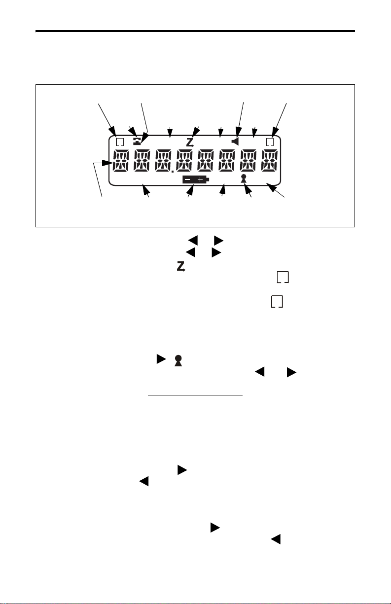
CONTROLS AND DISPLAY
On-Off/Volume
Microphone
Option
Switch
CONTROLS AND DISPLAY
Antenna Jack
Speaker
Accessory
Connector
Top Panel Controls
On-Off Volume - Turning this knob clockwise turns power on and sets
the volume level. Turning it counterclockwise to the detent turns power
off. Power is on when information appears in the display. For more
information on setting the volume, refer to page 20.
11
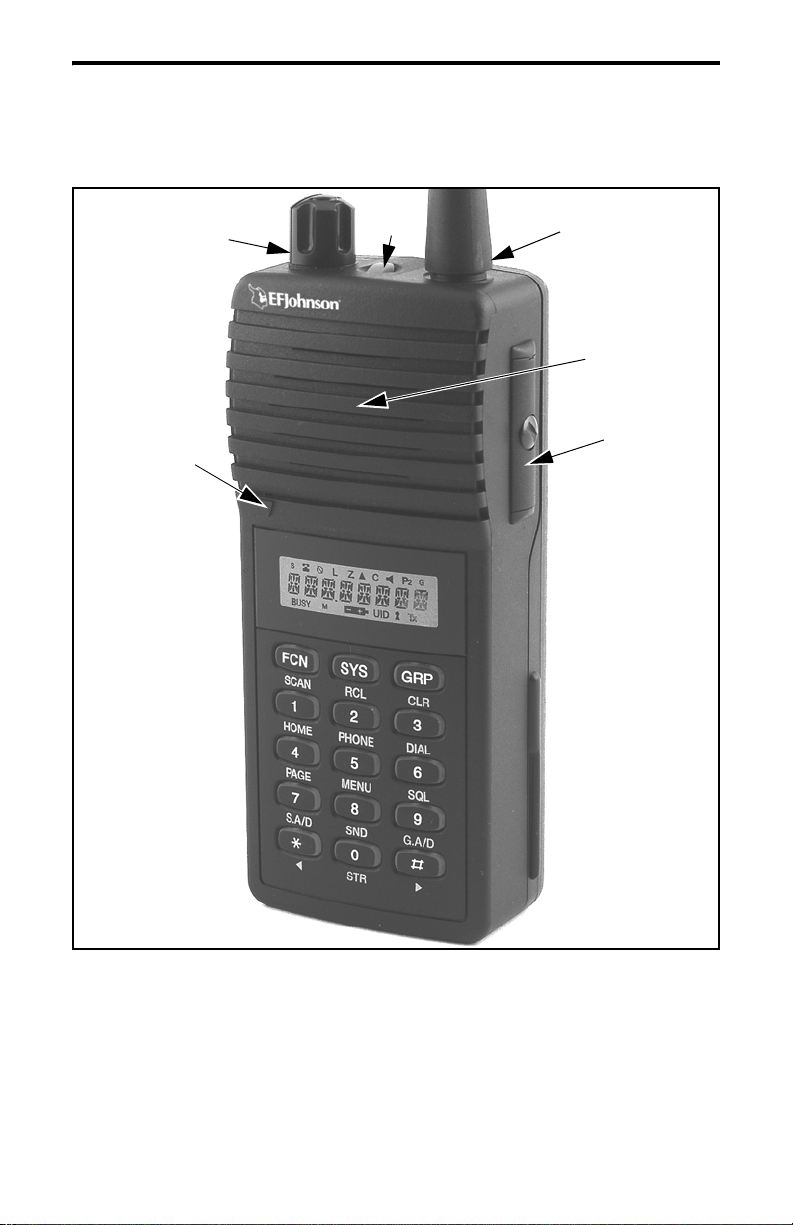
Page 11
CONTROLS AND DISPLAY
Option Switch 1 - This switch can be system operator programmed to
control a specific function (see page 35).
Antenna Jack - Connection point for the antenna.
Accessory Connector - When the protective cover is removed, this
connector can be used for connecting optional accessories.
Battery Release Button (Not shown) - This button is located on the
bottom end of the transceiver, and it is pressed to release the battery so
that it can slide downward and be removed from the radio.
Option
Switch 2
Option
Switch 3
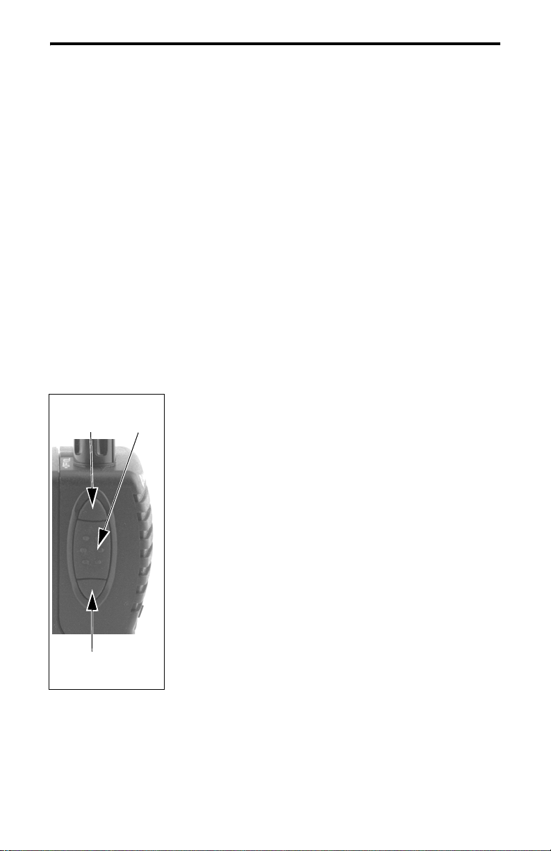
PTT
Switch
Side Controls
Option Switch 2 - This switch can be system
operator programmed to control a specific function
(see page 35).
PTT (Push-To-Talk) - Keys the transmitter so that a
message can be transmitted. The “
Tx” icon in the
display indicates when the transmitter is keyed.
Option Switch 3 - This switch can be system
operator programmed to control a specific function
(see page 35).
12
Page 12
CONTROLS AND DISPLAY
System
Scan List
Dial
Mode
S
BUSY
8-Character
Alphanumeric
Display
Phone
Group
Conv Ch
Busy
Low
Power
L
Battery
Low
Scan
Call
C
UID
UID/Aux
Group
Monitor
Priority
Keypad
P2
Tx
Lock
Group Scan
List
G
Transmitter
Keyed
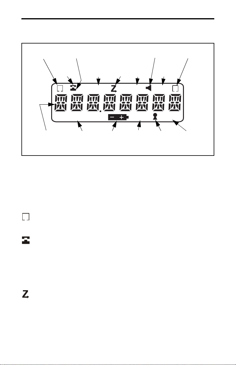
Display
8-Character Alphanumeric Display - This area of the display indicates
the selected system /group (see “System/Group Display Mode” on
page 20), the dialed number (see “Dial Mode” on page 37), error conditions, and other information.
- Indicates that the displayed system is in the scan list and scanned
S
normally (see “Scan List Programming” on page 42).
- The base portion of this icon is displayed when the displayed group
is programmed f or te lephon e c alls . The t op por tion (rece ive r) i s dis played
when the dial mode is selected (see page 37).
L - Indicates that the low-power mode is selected by the menu mode or a
low-battery condition (see page 26).
- Indicates that the scan mode is selected (see page 40).
C - Indicates that a call has been received on a group programmed for a
call indicator (see page 25). Press any key to turn this indication off.
13
Page 13

CONTROLS AND DISPLAY
P
2
- Indicates that the conventional monitor mode has been enabled by
the Monitor option switch (see page 49).
- “
P” indicates that the displayed group is an LTR-Net/LTR priority
1 group, and “
- Indicates that the displayed group is in the scan list and scanned
G
normally (see page 42).
BUSY - Indicates that the sele cted conven tional c hannel i s curren tly busy
with voice or other traffic.
recharged or replaced as soon as practical (see page 23).
UID - Indicates that the displayed group is programmed for an LTR-Net
Unique ID or Directed Group call (see page 46).
P2” indicates that it is a priority 2 group (see page 45).
- Indicates a low battery condition. The battery should be
- Indicates that the keypad has been disabled by pressing FCN
(page 22).
Tx - Indicates that the transmitter is keyed (push-to-talk switch pressed).
14
Page 14
CONTROLS AND DISPLAY
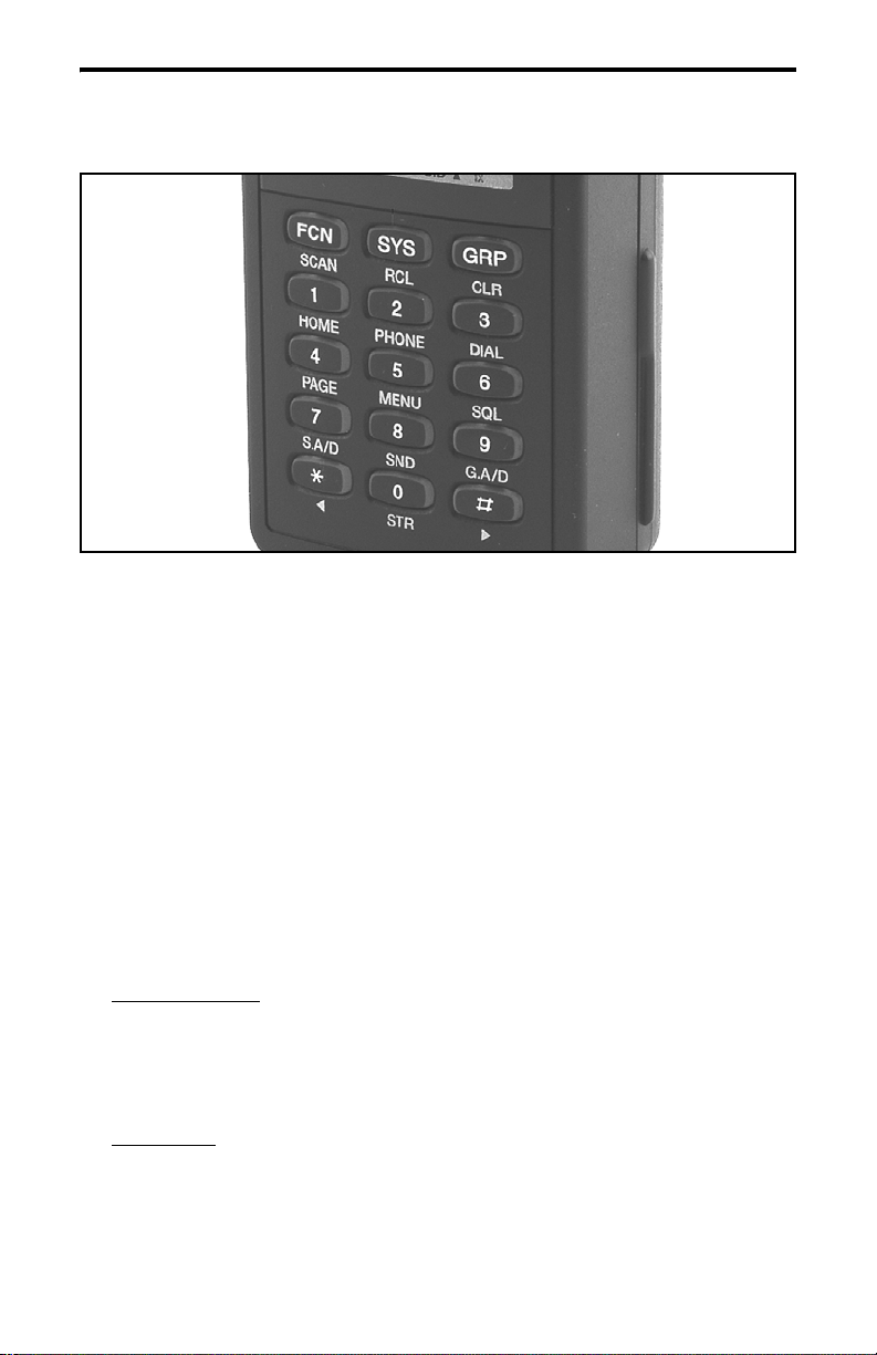
Front Panel Keys
Most front panel keys have two or more functions. The function on
the key is usually selected by simply pressing the key, and the function
under the key is usually selected by first pressing another key such as the
FCN key. In addition, some key functions may be available in the standard mode and others in the dial mode (see page 37). Also, all key
functions except 0-9 can be assigned to an option switch and controlled
by either (see page 35). Holding the key down causes repeating when
applicable. The front panel keys operate as follows:
FCN (SCAN)
Standard Mode
FCN - Enables the alternat e fun ction of the nex t key tha t is pr essed.
This alternate function is active for 2 seconds or until another key
is pressed.
FCN SCAN - Turns scanning on and off.
Dial Mode
FCN - Selects the alternate function of various keys as described in
the following information.
15
Page 15

CONTROLS AND DISPLAY
SYS (RCL)
Standard Mode
SYS - Selects the next higher system.
SYS - Selects the next lower system.
SYS (xx) - Directly selects specifie d system.
FCN RCL - Momentarily displays the revert (selected) system if it
is not already being displayed.
Dial Mode
RCL - Scrolls through the numbers programmed in memory.
FCN RCL (0-9) - Recalls the number stored in the specified
memory location.
FCN RCL - Recalls the last number dialed from memory.
FCN RCL - Recalls the last number dialed.
GRP (CLR)
Standard Mode
The GRP key functions the same as “SYS” just des cribe d to change
or display the selected group.
Dial Mode
CLR - Erases the last digit in the display.
FCN CLR - Erases the entire number in the display.
1 (HOME)
Standard Mode
FCN HOME - Selects the preprogrammed home system/group.
1 - Pressing this key with the PTT switch pressed transmits the “1”
digit.
Dial Mode
1 - Dials the “1” digit.
2 (PHONE)
Standard Mode
FCN PHONE - Selects the dial mode and a telephone group in the
current system.
2 - Pressing this key with the PTT switch pressed transmits the “2”
digit.
16
Page 16

CONTROLS AND DISPLAY
Dial Mode
2 - Dials the “2” digit.
FCN PHONE - Exits the dial mode and sends the call termination
code.
3 (DIAL)
Standard Mode
FCN DIAL - Selects the dial mode without changing the currently
selected group.
3 - Pressing this key with the PTT switch pressed transmits the “3”
digit.
Dial Mode
3 - Dials the “3” digit.
FCN DIAL - Exits the dial mode without sending the call
termination code.
4 (PAGE)
Standard Mode
FCN PAGE - The page function is currently not available.
4 - Pressing this key with the PTT switch pressed transmits the “4”
digit.
Dial Mode
4 - Dials the “4” digit.
5 (MENU)
Standard Mode
FCN MENU - Selects the menu mode.
5 - Pressing this key with the PTT switch pressed transmits the “5”
digit.
Dial Mode
5 - Dials the “5” digit.
6 (SQL)
Standard Mode
FCN SQL - Selects the squelch adjust mode for conventional
channels.
6 - Pressing this key with the PTT switch pressed transmits the “6”
digit.
17
Page 17

CONTROLS AND DISPLAY
Dial Mode
6 - Dials the “6” digit.
7 (S.A/D)
Standard Mode
FCN S.A/D (System Add/Delete) - Changes the scan list status of
the currently displayed system. The system is in the scan list an d
scanned normally if “ ” is displayed when not scanning.
S
7 - Pressing this key with the PTT switch pressed transmits the “7”
digit.
Dial Mode
7 - Dials the “7” digit.
8 (SEND)
Standard Mode
8 - Pressing this key with the PTT switch pressed transmits the “8”
digit.
Dial Mode
8 - Dials the “8” digit.
FCN SEND - Automatically accesses the radio system and trans-
mits the number in the display.
9 (G.A/D)
Standard Mode
FCN G.A/D (Group Add/Delete) - Changes the scan list status of
the currently displayed group. The group is in the scan list and
scanned normally if “ ” is displayed when not scanning.
G
9 - Pressing this key with the PTT switch pressed transmits the “9”
digit.
Dial Mode
9 - Dials the “9” digit.
0 (STR)
Standard Mode
FCN STR - Changes between the numeric and alpha display
modes.
0 - Pressing this key with the PTT switch pressed transmits the “0”
digit.
18
Page 18
CONTROLS AND DISPLAY
Dial Mode
0 - Dials the “0” digit.
FCN STR (0-9) - Stores the displayed number in the specified
memory location.
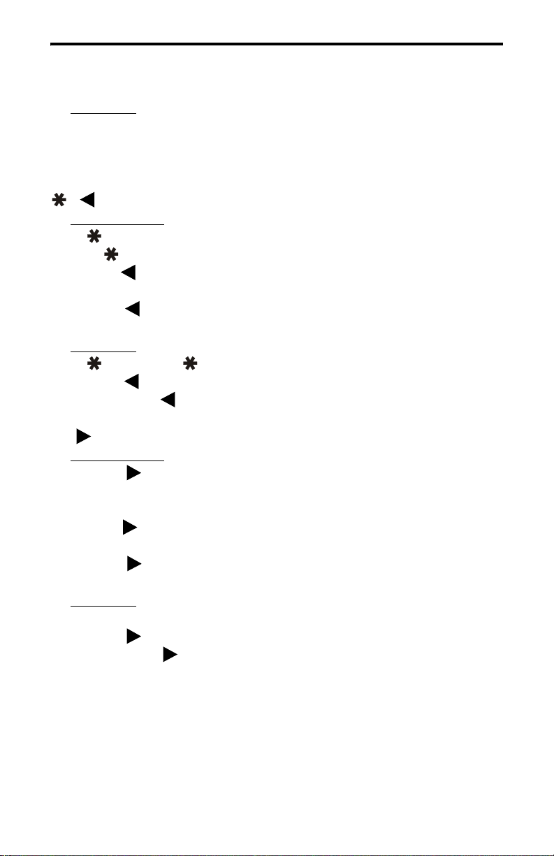
()
Standard Mode
- Pressing t his key with the PTT switch pressed transmits the
“ ” digit.
SYS - Selects the next lower system (see preceding “SYS” key
description).
GRP - Selects the next lower group (see preceding “GRP” key
description).
Dial Mode
- Dials the “ ” digit.
FCN - Enters a pause when dialing a telephone number.
FCN RCL - Recalls the last number dialed from memory.
()
#
Standard Mode
FCN - Enables and disables the keypad lock feature.
- Pressing this key with the PTT switch pressed transmits the “ ”
##
digit.
SYS - Selects the next higher sys tem (see preced ing “SYS” key
description).
GRP - Selects the ne xt highe r group (se e prece ding “GRP” key
description).
Dial Mode
- Dials the “ ” digit.
##
FCN - Displays the overflow digits for a short time.
FCN RCL - Recalls the last number dialed.
19
Page 19

BASIC OPERATIO N
BASIC OPERATION
Power-Up Sequence
When power is turned on using the top panel on-off/volume control,
the backlight turns on, all segments and icons in the display are momentarily enabled, and the las t sev en digits of the transceiver part number are
very briefly displayed. A beep then sounds (if tones are enabled) and the
transceiver is operational.
Backlight Operation
The display and keypad backlight automatically turns on for 3
seconds whenever power is turned on or any key is pressed. If the Backlight menu parameter is available (see page 35), selecting “On” enables
this operation and selecting “Off” disables the backlight entirely.
Setting Volume Levels
The relative volum e level can be determined by noting the position
of the index on the volume knob. You may also be able to enable a tone
or background noise for use in setting the volume as follows:
• If key press tone s are enabled, a sh ort tone so unds whenever any key is
pressed.
• If a conventional system is selected and the monitor option switch is
programmed (see page 49), press this switch and if someone is talking
on the channel, voice is heard. If no one is talking, the squelch can be
adjusted as descr ibed on page 48 and noise is heard. It is not possibl e to
manually unsquelch the transceiver when an LTR-Net or LTR system
is selected.
System/Group Display Mode
Two system/group display modes can be selected. One is a numeric
format and the other is an alpha tag format. To switch between these
20
Page 20

BASIC OPERATION
modes, press FCN STR. Turning power off does not change the selected
mode. These modes operate as follows:
Numeric Mode
Gxx” and the group alpha tag is not displayed. For example, System 1
and Group 2 are displayed as follows. When only group scanning is
occurring, the group number is replaced by dashes and the syst em
number continues to be displayed (see page 40).
Alpha Tag Mode - The group alpha tag is displayed and the system and
group numbers are not displayed. For example, the “CAR 220” system is
displayed as follows. Ther e is no speci al grou p scan i ndica tion whe n only
group scanning is occurring.
System and Group Select
- The system and group numbers are displayed as “Sxx
Numeric Display Mode
Alpha Tag Display Mode
Systems and groups are selected by the keypad SYS and GRP keys
and one or more other keys as follows:
• To increase the selected system, press SYS and then . Likewise, to
increase the selected group, press GRP . Holding the key down
causes the function to repeat. After the highest system or group is
selected, a tone sounds and wr ap-around to the lowest syst em or group
occurs.
• To decrease the selected sys tem, press S YS and then . Like wise, t o
decrease the selected group, press GRP . Holding the key down
causes the function to repeat. After the lowest system or group is
21
Page 21

BASIC OPERATIO N
selected, a tone sounds a nd wrap-around to the highest system or gr oup
occurs.
• To directly select a system or group number, press SYS or GRP and
then the number of the desir ed syst em or gr oup. For example, to s elect
Group 9, press GRP, 0, 9. A leading “0” mus t be ent ere d fo r di gits 1-9
for the selected system or group to change.
Keypad Disable
Occasionally, the front panel keys may be accidentally pressed, for
example, if you carry the transceiver on your belt and it brushes against
an object. To prevent this from happening, the front panel keys can be
disabled. To disable and enable the keypad, press FCN . The locked
condition is indicated by the icon. If a key is pressed with the keypad
locked, all that happens is “LOCKED” is displayed. The top and side
panel controls remain functional with th is feature selected. Turning the
power off and then on again does not unlock the keypad.
Transceiver Lock
The transceiver can be locked to prevent unauthorized usage. To
lock the transceiver, press FCN and “PASSWORD” is then displayed
to indicate that a four-digit unlock password must be entered. This password can be any f our-digit number except “0000”. The pa ssword must be
re-entered to confirm it and the transceiver is then locked as indicated by
“LOCKED” in the display. To unlock the transceiver, the four-digit password is re-en tered.
When the transceiver is in t he lock mode , cal ls can not be re ceived or
transmitted. In addition, all controls except the on-off/volume control are
disabled. The transceiver then remains unlocked until it is locked again
by repeating this sequence.
Since the password is not preprogrammed, a different password can
be entered each time this feature is used. If the password is forgotten, the
transceiver must be returned to your system operator for reprogramming
to make it operational again.
22
Page 22

BASIC OPERATION
Low Battery Indication
When the battery voltage drops to the point where recharging is
required, the icon is indicated in the bottom part of the display.
In addition, a beep sounds when this in dication initially appears and when
the push-to-talk switch is released (if the key press tone is enabled). The
battery should be recharged as soon as possible after this indication
appears (see page 57).
Current settings of switches and other parameters are saved in
memory during a low-battery condition, and low transmit power is automatically selected (indicated by “
L” in display). The low-battery indica-
tion is cleared by turning power off and then on again.
Option Switches
This transceiver has three option switches that can be programmed
by your system operator to control the monitor function and most functions that are selectable by the front panel keys (see table on page 34).
The option switches are the push-button switch on the top panel and the
switch immediately above and the switch immediately below the PTT
switch on the side panel (see page 12).
LTR-Net, LTR, and Conventional Operation
Introduction
Each selectable system can be programmed for LTR-Net, LTR, or
conventional operation. The type of operation that is programmed is
determined by the radio equipment being used by your system operator.
There are a few differences in operation that are described in the
following information and also noted elsewhere in this manual as
required.
23
Page 23

BASIC OPERATIO N
LTR-Net and LTR Operation
The LTR-Net and LTR modes provide automatic channel selection
and monitoring before transmitting. Special tones and display messages
indicate busy and out-of-range conditions, and telephone calls can be
placed almost as conveniently as with your home telephone.
Selecting a system selects a collection of up to 99 groups. Selecting
one of these groups selects an ID code which determines the type of call
(standard group, telephone, or special), the specific mobile or mobiles is
being called (if applicable), and what calls are received. In addition,
higher priority calls may be received (see page 45).
The LTR-Net operating mode provides the most operating features.
Exclusive LTR-Net features inc lude roamin g and Unique ID and Direct ed
Group calls. When operating in LTR-Net sites, calls may be made to
mobiles in other sites as well as the current site. LTR-Net and LTR
features are described starting on page 45.
Conventional Operation
In the conventional mode, selecting a system selects a conventional
channel, and selecting a group selects the special Call Guard squelch
coding (if used) and other unique parameters on that channel such as call
indicator operati on. The Call Guard coding deter mines the mobile or group
of mobiles being calle d and also the mobiles from which ca lls are received
(see “Call Guard Squelch” on page 51).
In the conventional mode, a busy co nditi on is d etect ed a utomati call y
if the Transmit Disable On Busy feature is used. Otherwise, it must be
detected manually as described in “Monitoring Before Transmitting” on
page 49. Unsuccessful access conditions cannot be detected with conventional signaling, so are not indicated by special tones or display
messages. Refer to “Operation At Extended Range” on page 60 for information on how to determine if an out-of-range condition may exist.
24
Page 24

GENERAL FEATURES
GENERAL FEAT URES
Bank Select
A bank is a coll ect io n of selectable systems that have been set up for
a specific application. For example, one bank could be programmed for
operation in Minneapolis and another for operation in Milwaukee. Up to
sixteen banks can be programmed, and each bank is identified by a
unique alpha tag.
Banks are s elected by the BANK SEL menu parameter. In the menu
mode select the “BANK SEL” par amet er a nd t he n the desired bank (refer
to page 35 for more menu mode information). If this menu parameter is
not available, banks are not selectable.
Call Indicator
The call indicator is “C” in the upper part of the display (see
following illustration). The purpose of this indication is to show that a
call was received while you were away from the radio. Individual groups
can be programmed for this feature and it then turns on when a call is
received on one of those groups.
C
This indicator is turned off by pressing any button or cycling power.
If scanning and the “Last Received” configuration is programmed (see
“Transmitting In The Scan Mode” on page 43), the system and group of
the last call are displ ayed. Othe rwise, the cu rrent ly sele cted sys tem/gr oup
is displayed.
Call
Indicator
25
Page 25

GENERAL FEATURES
Home System/Group Select
To select the preprogrammed Home system/group, simply press the
FCN HOME. The Home system/group programm ed for the current bank
is then displayed and it becomes the selected system/group. If no home
system/group has been programmed, this function is not available.
Proceed (Clear-To-Talk) Tone
This is a short tone that sounds shortly after the PTT switch is
pressed to indicate that the radio system has been accessed and speaking
can begin. This tone can be programmed to be a single or distinctive (3beep) tone. With encrypted calls, a special double beep sounds.
This tone always sounds with LTR-Net and LTR standard calls if
tones are enabled by the TONES menu parameter (see “Tone Select” on
page 27) or system operator programming. It can also be programmed to
sound with conventional calls and/or LTR-Net and LTR auxiliary and
telephone calls (first access only).
On LTR-Net and LTR systems, if the radio system is busy when
making a call, the busy tone sounds instead of the proceed tone and
“BUSY” is i ndicated in the display. If an access attempt is unsuccessful,
such as because of an out-of-range condition, the intercept tone sounds
and “NO ACESS” is indicated in the display. Refer to page 52 for more
information on these condit ion s.
If the proceed tone is enabled on conventional systems and the
Transmit Disable On Busy feature is used to automatically perform monitoring (see page 50), the proceed tone does not sound if the channel is
busy. Otherwise, it sounds even if the channel is busy.
Receive-Only Groups
Any group can be programmed for monitoring only (transmitting
disabled). If the PTT switch is pressed with one of these groups selected,
the intercept tone sounds and “TX DISBL” is displayed.
26
Page 26

STANDARD GROUP CALLS
Time-Out Timer
The time-out timer disables the transmitter if it is keyed continuously for longer than the programmed time. It can be programmed for
0.5 - 5.0 minutes or disabled entirely. If the transmitter is keyed continuously for longer than the programmed time, the transmitter is disabled,
“TIMEOUT” is indicated in the display and the intercept tone sounds.
The timer and tone are reset by releasing the PTT switch.
One use of the time-out timer feature is to prevent a repeater from
being kept busy for an extended period by an accidentally keyed transmitter. It can also prevent possible damage to the transmitter caused by
transmitting for an excessively long period.
Tone Select
If the TONES menu parameter is selectable, the tones that sound can
be selected. Otherwise, the tones that sound are fixed by programming.
The following choices are available. Refer to page 35 for more information on using the menu mode.
Silent - All tones are disabled.
Keys - Only the key press tones are enabled.
Alerts - All tones except the preceding key press tones are enabled.
All - Both the key press and alert tones are enabled.
STANDARD GROUP CALLS
General
Most calls you make are probably the sta ndar d group type described
in this section. Thes e calls are bet ween you and ano ther mobi le or con trol
station. The main difference between these calls and the other types is
that no number needs to be dialed. The foll owing procedure applies to all
three types of operation (LTR-Net, LTR, and conventional).
27
Page 27

STANDARD GROUP CALLS
Placing a Standard Group Call
1. Turn transce ive r powe r on and se t th e vo lu me as described starting on
page 20. With conventi ona l op eration, also make sure that the squelch
is properly set as described on page 48.
2. Select the system and group of the mobil e being cal led as des cribed on
page 21.
3. If a conventional call is be ing placed, moni tor the cha nnel manuall y or
automatically as described on page 49.
4. Press (and hold) the micr ophone PTT (push-to-tal k) swit ch to talk and
release it to listen. Opera tion with LTR-Net, LTR, and conventional
calls is as follows:
LTR-Net and LTR Operation
• If tones are enabled, the proceed tone sounds shortly after the PTT
switch is pressed if the radi o sys tem was suc ces sf ully accessed (see
page 26). If tones are not enabled, no tone sounds when the system
is successfully accessed.
• If the radio system is busy, the busy tone sounds (see page 52) and
“BUSY” is indicated in the display. Additional access attempts
continue as long as the PTT switch is pressed.
28
Page 28

STANDARD GROUP CALLS
• If the radio sys tem could n ot be acce ssed b ecause of an out-of -range
condition or some other reason, the intercept tone sounds (see
page 52) and “NO ACESS” is indicated in the display. The PTT
switch must then be released and pressed again to make another
access attempt.
• When responding, busy or no access conditions may also occur, the
same as when placing a call becau se the rad io syste m is re- acces sed
for each transmission with these calls.
Conventional Operation
• If the channel is busy and the Transmit Disable On Busy feature is
programmed (see page 50), “DSBL BSY” is indicated in the display
and the transmitter is disabled. Any channel activity is heard while
the PTT switch is pressed.
• Otherwise, busy and out-of-range conditions are not indicated and
speaking can begin whe n the P TT s witch is pres sed (if the ch annel is
not busy). If the pr oceed t one is e nabled on co nventi onal sy stems, i t
indicates when speaking can begin but does not indicate that the
channel is free or has been successfully accessed.
Receiving a Standard Group Call
1. Select or scan the syst em and gr oup p rogrammed for t he cal l you want
to receive (see page 40 for scan information).
2. When the message is received, the display changes to the system and
group of the call. Press the PTT switch to talk and release it to listen. If
scanning, a response may not automatically occur on the group of the
call. Refer to “Transmitting In The Scan Mode” on page 43 for more
information.
29
Page 29

TELEPHONE CALLS
TELEPHONE CALLS
General
NOTE: Telephone calls can be placed and received only if that service is
available to you and your transceiver has been programmed
appropriately.
The telephone calling feature allows you to place and receive telephone calls using your transceiver. The following information describes
how these calls are made with LTR-Net and LTR operation. If you can
make telephone calls with conventional operation, the procedure may be
somewhat different and your system operator may provide additional
information. Proceed as follows:
Placing Telephone Calls
1. Turn transce ive r powe r on and se t th e volume as described starting on
page 20.
2. Select the dial mode and a telephone group as follows. When the dial
mode is selected, the handset portion of the telephone icon is
displayed, and the n when a telephone group is s elected, the base po rtion
is displayed.
• T o select th e dial mode and a preprogrammed tele phone group, pres s
FCN PHONE.
• To select the dial mode without changing the selected group, press
FCN DIAL. Then manually select a telephone group if required.
3. Dial the desired number usi ng t he ke ypad or recall it from memory by
pressing FCN RCL and the location number (0-9). Refer to the dial
mode description starting on page 37 for more information.
4. To send the telephone number, briefly press the PTT switch to access
the system and then press FCN SND. Landside ri nging (or busy) should
then be heard. The following conditions may also occur:
30
Page 30

TELEPHONE CALLS
• If the radio system is busy or could not be accessed, busy or no
access conditions are indicated the same as described for standard
group calls on page 28.
• With LTR-Net operation, a short tone sounds to indicate that the
number was accepted by the system.
5. When the other party answers, press the PTT switch and respond. The
PTT switch must be pressed to talk and released to listen (the same as
with standard group calls).
6. When the call is finished, it should be terminated and the dial mode
exited. The call is usually terminated by transmitting either the or
characters.
#
To automatically send these characters and exit the dial mode, press
FCN PHONE. To exit the dial mode without sending these characters,
press FCN DIAL. T er mination is indica ted by three be eps. T ermi nating
the call in this manner prevents extra bill ing that may occur while the
system automatically detects the end of the call.
#
Receiving a Telephone Call
1. Select or scan the system and group programmed for telephone calls.
When a telephone group is selected, the base portion of the telephone icon is displayed.
2. When “ringing” is heard, press the PTT switch and respond. The PTT
switch must be pressed to talk and released to listen the same as with
standard calls.
3. When the call is finished, terminate it as described in step 6 of the
preceding section.
31
Page 31

LTR-NET AUXILIARY CALLS
Landside-Originate Telephone Calls
If telephone calls can be placed, it is usually possible to receive telephone calls from a landside telephone. With some radio systems, each
mobile is assigned a unique telephone number so that it can be dialed
directly. With others, the number of the radio system is dialed and then
when a tone sounds, the number specifying the mobile being called is
dialed. The mobile user he ars “ringing” when a telephone call is rec eived.
Contact your system operator for the number to dial and other information on how to place these calls.
LTR-NET AUXILIARY CALLS
General
The LTR-Net auxiliary calls are Unique ID and Directed Group
calls. Unique ID calls are placed to specific mobiles, and Directed Group
calls are placed to specific talk groups. These calls can be m ade to other
mobiles in your site or some other site that is part of your radio network.
As with telephone calls, a special number must be dialed to place
these calls. The number dialed is 1-10 digits long, and is provided by
your system operator. Other requirements to place these calls are they
must be authorized on the radio system and your transceiver must be
properly programmed. Refer to page 46 for more information on LTRNet calls.
Placing LTR-Net Auxiliary Calls
1. Turn transce ive r powe r on and se t th e vo lu me as described starting on
page 20.
2. Select the LTR-Net system and group programmed for auxiliary calls.
When an auxiliary call group is selected, “
lower part of the displ ay . If the gr oup alpha tag is dis played, it may al so
indicate when one of these groups is selected.
32
UID” is indicated in the
Page 32

LTR-NET AUXILIARY CA LLS
3. Select the dial mode by pressing FCN DIAL. This mode is indicated
when the handset portion of the telephone icon is displayed.
4. Dial the desired numb er which specifies t he mobile or group of mobiles
being called. If it has been previously stored, this number can be
recalled from memory by pressi ng FCN RCL and the locat ion number
(0-9). Refer to the dial mode description starting on page 37 for more
information.
5. T o send the number, br iefly press the P TT switch and then wh en the dial
tones sounds, press FCN SND. Another tone then sounds to indicate
that the call was accepted by the system. The call then proceeds as
follows. If this tone does not sound, an unauthorized or incorrect
number may have been dialed. If all system resources are busy , the cal l
is placed in a queue as described in “Busy Queuing” on page 46.
Unique ID Call - Ringing is hear d to indica te that t he other t ransceiver
is being rung. If there is no answer, ringing automatically stops after
several rings and the call is terminat ed. When the oth er party ans wers,
respond as with a standard call.
Directed Gro up Call - A second tone sounds to indicate that the path
is complete and speaking should begin. No ringing occurs.
6. When the call is complete, it should be terminated the same as
described in step 6 on page 31. Three beeps indicate that the call has
been terminated.
Receiving Auxiliar y Calls
To receive a Unique ID call, all that is required is that an LTR-Net
system is selected that contains a group programmed for those calls. To
receive a Directed Group call, the group of the call usually needs to be
selected or scanned. A Unique ID call is indicated by a “ringing” tone
similar to telephone calls, and a Directed Group call is indicated by the
caller’s voice the same as with standard group calls.
33
Page 33

OPTION SWITCHES AND MENU MODE
The transceiver may be programmed so responses always occur on
the last selected group. In this case, the group may need to be manually
changed to respond to these calls (see “Transmitting In The Scan Mode”
on page 43). Unique ID and Directed Group cal ls can also be p laced f rom
a landside telephone. The same numbers are dialed as when the call is
mobile originated. Cont act your sys te m o per at or f or more information on
how to place these calls.
OPTION SWITCHES AND MENU
MODE
Menu Mode and Option Switch Functions
Function Menu Items
Backlight mode select BACKLGHT 20
Bank select BANK SEL 25
Monitor mode select X 50
Roaming on-off [2] ROAMING 47
Scan type select SCN TYPE 40
Scan continue on-off SCN CONT 43
Scan list save mode SCN SAVE 42
Tone type select TONES 27
Any keypad function [3]
NOTES:
1. Functions left blank are not available.
[2] Available with LTR-Net operation only.
[3] The option switches can be programmed for any of the functions
selectable by the keypad keys except 0-9.
34
Option
Switch
See Descrip.
on Page
Page 34

OPTION SWITCHES AND MENU MODE
Option Switches
The push-button switch on the top panel (see page 11) and the
switch immediately above and the switch immediately below the PTT
switch on the side panel (see page 12) are programmable by your system
operator. The functions which can be controlled by these switches are
basically the functions that are selectable by the front panel keys plus
monitor mode select (see “Option Switch” column of the preceding
table). This provides a “quick select” for these functions. Some functions
may be controlled by both the keypad and an option switch, and some or
all option switches may be disabled.
Menu Mode
Introduction
The menu mode is selected by pressing FCN MENU. Functions
which can be controlled by the menu mode are indicated by an entry in
the “Menu Items” column of the preceding table. More information on
each function can be f ound on th e page ind ic ated in this
table. Parameters
are not displayed in the menu mode if they are not used, in a fixed state,
or controlled by only an option switch. Calls cannot be received or transmitted while the menu mod e is selected.
Using Menu Mode
A flowchart of the menu mode is shown on the next page. Proceed
as follows to select functions using the menu mode:
1. Select the menu mode by pres sing FCN MENU. The fi rst menu p aram-
eter is then displayed.
2. To scroll through the available menu parameters, press the (scroll
down) and (scroll up) k eys. Then to display and chang e the selected
option for a parameter, proceed as follows:
35
Page 35

OPTION SWITCHES AND MENU MODE
• To display the selected option for a parameter, press the STR key.
• To change the selected option, press the and keys.
• T o exit back to the parameter and save the selected optio n, press FCN
STR.
• To exit back to the parameter without changing the selected option,
press STR.
3. When the desired condition of each menu paramet er is selected, exit the
menu mode by pressing FCN MENU again. The menu mode is also
automatically exit ed 2 seconds after a change is made or 8 seconds aft er
no changes are made.
Enter/Exit
Menu Mode
Press FCN MENU
36
MENU
PARAMETERS
Select by
pressing
BANK
SEL
Other Menu
Parameters
PARAMETER
OPTIONS
Press
Bank 1
STR
Bank 2
Bank x
Menu Mode Flowchart
Page 36

DIAL MODE
DIAL MODE
Introduction
When placing calls that require a number be dialed (telephone and
auxiliary), using the dial mode allows the number to be dialed at any
convenient rate, dialing errors to be corrected, and then the radio system
to be automatically accessed and number transmitted when desired. The
dial mode also allows up to ten 16-digit numbers to be stored in memory
and later recalled.
When in the dial mode, the SYS and GRP keys become RCL
(Recall) and CLR (Clear) keys. Therefore, the selected system and group
cannot be changed when the dial mode is selected. The information
which follows describes how the dial mode is used.
Selecting Dial Mode
Selecting Dial Mode and Telephone Group - To select the dial mode and a
telephone group in the cur rent system, press FCN PHONE. If there is more
than one group programmed for t elephone calls in the current system, the
first high numbered telephone group is selected. If there is no telephone
group or a convention al system is sele cted, “NO PHONE” is displ ayed and
an error tone sounds.
Selecting Dial Mode W ithout Changing Selecte d Group
mode without changing the currently selected group, press FCN DIAL.
This method should be used when placing auxiliary calls because the
auxiliary call group and not the telephone group must be selected.
The dial mode is indicated when the handset portion of the telephone icon is displayed. The base portion is displayed when a telephone group is selected, and “
group is selected.
UID” is displayed when an auxiliary call
- T o select the dial
37
Page 37

DIAL MODE
Dialing a Number
Enter the desired number by pressing the 0-9, , and keys. Other
dialing functions are as follows:
#
• Only the last 8 digits dialed are displayed. To momentarily display
the upper 8 digits, press FCN .
• T o erase the last digit, press the CLR key (hold it down to repeat). T o
erase the entire number, press FCN CLR.
• To enter a pause, press FCN (each pause equals one character).
Sending the Number
Briefly press the PTT switch to access the radio system. Then to
send the number in the display, press FCN SND. The keypad remains
active while in a conversation to allow additional numbers to be dialed.
Simply press the PTT switch and dial the number. The number in the
display does not change when a number is dialed in this manner. If you
want to save the number in the display (see following information), make
sure you do so before the dial mode is exited.
Storing Numbers in Memory
Up to ten 16-digit numbers can be stored in memory and later
recalled. Proceed as follows to store a number:
1. Enter the number as described in the preceding “Dialing a Number”
section.
2. To store the number, press FCN STR and the memory location from
0-9.
3. If there is alrea dy a number in the selected location, it is replaced by the
new number. To clear a memor y l oca ti on, s impl y s tor e a bl ank display.
38
Page 38

DIAL MODE
NOTE: The character is stored and sent normally (no pause occurs),
and the character should not be stored because it may terminate the
#
call when it is sent.
Recalling Numbers From Memory
From Specif ic Location - FCN RCL 0-9 (location number)
Stored in Next Location
- RCL (hold down to repeat). If a number is
already displayed, the number in the next higher location is indicated; if
display is blank, the number in location 1 is indicated first.
Last Number Dialed by Recalling from Memory
Last Number Dialed
- FCN RCL
- FCN RCL
Exiting Dial Mode
Without Sending Call Termination Characters - To exit the dial mode
without sending the call termination characters, press FCN DIAL.
Sending Call Termination Characters
- To exit the dial mode and send the
characters which automatically terminate the call, press FCN PHONE.
Terminating a call in this manner prevents any additional billing for the
time required to automatically detect the end of a call.
Placing Calls Without Selecting Dial Mode
Telephone and Auxiliary calls can also be placed without selecting
the dial mode by using the procedure which follows:
1. Access the radio system by briefly pressing the PTT switch.
2. When a dial tone is heard, dial the desired number while pressing the
PTT switch. If too much time elapses between digits, the call is
automatically terminated.
NOTE: When receiving telephone or auxiliary calls, the selection of the
dial mode is optional because it does not enhance operation.
39
Page 39

SYSTEM AND GROUP SCANNING
SYSTEM AND GROUP SCANNING
General
Introduction
The scan feature monitors , in sequ ence, t he sys tems a nd/or groups in
the scan list. When a message is detected that the transceiver is
programmed to receive, scanning stops and the message is received.
Shortly after the message is complete, scanning resumes (unless it has
been disabled). System and group scanning or group scanning only may
be used (see next page), and the operation of each type is as follows.
Refer to page 23 for more information on systems and groups.
System Scanning
If system scanning is not us ed, calls are detected on only the currently
selected system.
Group Scanning
These groups are from the selected system and also from scanned
systems if system scanning. If group scanning is not used, calls are
detected on only the selected group. In addition, calls may be detected
on higher priority LTR-Net and LTR groups (see “Priority Calls” on
page 45).
Scan On-Off
System and/or group scanning are turned on and off by pressing
FCN SCAN. When either type of scanning is enabled, is indicated in
the display (see following illustration). Then when group scanning is
actually occurr ing , da shes are displayed instead of a group number (if the
numeric display mode described on page 20 is selected). Group scanning
is not indicated if t he alpha di splay mode is selected, and system sca nning
is never indicated. The monitor mode must be disabled for scanning to
occur (see page 49).
- Detects calls on all syst ems i n th e system scan list.
- Detects calls on all groups in the group scan list.
40
Page 40

SYSTEM AND GROUP SCANNING
System Scan List Group Scan List
S
System or Group
Scanning Selected
Group
Scanning Occurring
G
Scan Types
The type of scanning selected is determined by the menu mode SCN
TYPE parameter (see page 35). If it is not selectable, the scan type is
fixed by system operator programming. The available scan types are as
follows.
SYSTEMS - Both system and group
GROUPS - Group scanning only
OFF - Both types disabled (scanning not selectable)
If the SCN TYPE menu parameter is disabled, the scan type is fixed
by programming. The selected system and group can be changed while
scanning using the SYS and GRP keys in the normal manner. Scanning
resumes shortly after the change is made.
When a call is received in the scan mode, the display changes to the
system and group of the call. Programming determines if this change is
temporary or permanent, and if a response occurs on the system/group of
the call or the selected system/group. Refer to “Transmitting In The Scan
Mode” on page 43 for more information.
LTR-Net Mode Scanning
When system scanning with an LTR-Net system selected and
roaming disabled, only t he LTR-Net systems in the scan l ist that acces s the
site of the selected system are scanned (any LTR and conventional
41
Page 41

SYSTEM AND GROUP SCANNING
systems are not sc anned). If roaming is enable d, regist ration o n other si tes
occurs normally and scanning of LTR-Net systems occurs as just
described.
However, if the current LTR-Net site is lost and no other LTR-Net
site can be located, the LTR and conventional systems in the scan list are
also scanned. Searching for an LTR-Net sit e con ti nue s and i f one is aga in
detected, registration on that site occurs and the LTR and conventional
systems are no longer scanned. This operation can provide uninterrupted
operation in areas which have not been converted to LTR-Net operation.
LTR and Conventional Mode Scanning
When an LTR or conventional system is selected with system scanning enabled and roaming disabled, scanning is sequential through only
the LTR and conventional systems in the scan list (LTR-Net systems are
not scanned). If roaming is enabled, only LTR-Net systems or all three
system types may be scanned as described in the preceding LTR-Net
description.
Scan List Programming
General
NOTE: The selected (displayed) system and group are always scanned
even if they have been deleted from the scan list.
NOTE: Deleting LTR-Net systems from the scan list also deletes them
from locality searching when roaming, even if scanning is disabled.
The scan list status of the displayed system is changed by pressing
FCN S.A/D, and the status of the displayed group is changed by pressing
FCN G.A/D. The displayed system is in the scan list and scanned
normally when is displayed, and the displayed gr oup is scanned when
is displayed (see preceding illustration). Deleting a system only
temporarily deletes the groups associated with that system because when
a system is added back into the scan list, the original group scan list is
again active.
42
Page 42

SYSTEM AND GROUP SCANNING
Systems and groups can be deleted from the scan list in the normal
manner while listening to a message on the system or group by simply
pressing the S.A/D or G.A/D key. Scanning resumes shortly after the
system or group is deleted.
Saving Scan List
If the menu mode SCN SAVE parameter is available (see page 35),
you can select if scan list changes are saved. If “On” is selected, changes
are saved as they are made and the scan list does not change when power is
turned off. Conversely, if “Off” is selected, they are not saved and the
default status of all systems and groups is reselected when power is turned
on. If the menu SCN SAVE parameter is not selectable, the scan list save
mode is fixed in one of these states.
Scan Delay and Continue Timers
When a message is received or transmitted while scanning, there is a
short delay before scanning resumes. The delay after receiving a call
prevents another message from being received before a response can be
made. Likewise, the delay after transmitting a call ensures that you hear a
response to your call instead of another message occurring on some other
system or group. Note that scanning does not resume if it has been
disabled, such as by selecting the monitor mode.
There is also a scan continue timer that may be programmed. This
timer controls the maximum time that a call is received before scanning
resumes. Times up to 60 seconds can be programmed. This prevents scanning from being delayed for long periods by lengthy calls. If the menu
SCN CONT parameter is selectable (see page 35), this feature can be
turned on and off.
Transmitting In The Scan Mode
General
When messages are received while scanning, programming determines if the sele cted system/ group does not change, change s perma nently
43
Page 43

SYSTEM AND GROUP SCANNING
to the new system/group, o r changes tem porarily. This in turn affects the
system/group on whi ch responses occur. T he dis p la y a lwa ys indicates the
system/group on which a call is received, but this may not be the system/
group on which a response occurs. The three programmable configurations operate as follows:
Last Selected - Transmissions always occur on the system/group that
was selected manually by the SYS and GRP keys or automatically by
roaming. Therefore, to respond to a message that is not on the selected
system/group, the selected system/group must be changed using one of
these methods:
• Select the system/group of the call manually using the SYS and GRP
keys.
• Before scanning re sumes, exit the scan mode by pressing FCN SCAN.
The system/group of the call then becomes the selected system/group
and it is not necessary to change it manually.
Last Received - The selected system/group changes to the system/group
of a call. Therefore, you can always respond to a call without having to
manually change the system/group. To return to the previously selected
system/group, it must be manually selected using the SYS and GRP keys.
Temporary Last Received - The system/group changes to the system/
group of a call for only the duration of the scan delay period (see
page 43). Then when the delay expires and scanning resumes (if it is not
disabled), the selected system/group is again displayed. Therefore, you
can respond to a call without changing the selected system/group as long
as you do so before scanning resumes.
44
Page 44

LTR-NET AND LTR FEATURES
LTR-NET AND LTR FEATURES
Transmit Inhibit
The Transm it Inhibit feature prevents the transmitter from keying if
the mobile you ar e c all i ng i s busy with another call. When the trans mi tt er
is disabled by this feature, the intercept tone sounds and “TX INHIB” is
displayed (see following illustration). To make another call attempt, the
PTT switch must be released and pressed again. However, you may want
to wait a few seconds before making another attempt because a timer
must time out before another attempt will be successful. A similar
Transmit Disable On Busy feature is available on conventional systems
(see page 50).
Priority Calls
Each LTR-Net and LTR group is programmed with a rec eive prior ity
number. If a call is detected on a group in the group scan list that has a
higher priority than the selected group, it is received (even if scanning is
not enabled). If another call is in progress when the higher priority call is
detected, the current call is immediately dropped. Some groups, such as
those used to make telephone calls, may be programmed as not interruptible to prevent other calls from interrupting a call in progress.
The system/ group of the pr iority call is displayed while it is
received. The programming described on page 43 determines if the
change is temporary or permanent and if a response occurs on the last
selected or received system/group.
45
Page 45

LTR-NET FEATURES
LTR-NET FEATURES
NOTE: Other LTR-Net features are described starting on page 45.
LTR-Net Standard Calls
Standard group calls are between two mobiles or between a mobile
and a control station. To place these calls in the LTR-Net or LTR mode,
simply select the desired group and press the PTT switch (no number is
dialed) as described starting on page 27.
LTR-Net Special Calls
The LTR-Net Special calls are as follows:
Special
Telephone Calls
Telephone
Auxiliary
- These calls allow you to place and receive telephone
Unique ID
Directed Group
calls using your transceiver. They are described starting on page 30.
Auxiliary Calls
- As shown in the preceding illust ration, these ca lls include
Unique ID and Directed Group calls. Unique ID calls are to specific
mobiles, and Directed Group calls are to specific talk groups. Refer to
page 32 for information on placing and receiving Auxiliary calls.
Busy Queuing
If system resources are not available when placing special calls,
queuing may be provided by the radio system. Standard group calls are
not queued. When a call is placed in a queue, a voice message informs
you that this has occurred. Then when resources become available, the
call is automatically placed and the normal ringing or other tones are
heard if applicable. If the call cannot be placed in the al lotted time, it is
terminated and another message informs you that this has occurred.
46
Page 46

LTR-NET FEATU RES
Roaming
LTR-Net radio localities (sites) can be linked together to provide
wide area coverage. Calls can then be automatically routed to your
current location as you travel from locality to locality. Both standard
group and special calls may be routed in this manner. If your transceiver
is programmed for roaming, this feature is utilized as follows:
1. Enable roaming using the ROAMING menu para meter (see page 34) if
available. If the menu paramete r is not availa ble, roaming is f ixed in the
on or off mode by programming.
2. If scanning is disabled, an LTR-Net system must be se lected. I f system
scanning is enabled , any system can be selec ted if the L TR- Net systems
are in the sy stem scan lis t (see page 42).
When roaming is enabled as just described and the signal from the
current locality becomes weak, the transceiver automatically begins
searching for anot her locality. While searching is occurring, “LCL
SRCH” is displayed as shown below. Then when a new locality is
located, registra tion o ccurs and “LCL SRCH” is no lon ger di splaye d. The
displayed system is then the next LTR-Net system programmed with a
different locality that could be accessed, and the displayed group is
usually the group that was displayed before roaming occurred.
NOTE: Deleting LTR-Net systems from the scan list also deletes them
from locality search when roaming, even if scanning is disabled. Therefore, make sure none have been inadvertently deleted (see page 42).
47
Page 47

LTR FEATURES
LTR FEATURES
NOTE: Other LTR features are described starting on page 45.
Standard Group Calls
Standard group calls are between two mobiles or between a mobile
and a control station. To place these calls in the LTR or LTR-Net mode,
simply select the desired group and press the PTT switch (no number is
dialed). The procedure for placing and receiving these calls is described
starting on page 27.
Telephone Calls
Telephone calls allow you to place and receive calls over the public
telephone system using your transceiver. LTR and LTR-Net telephone
calls are described starting on page 30.
CONVENTIONAL FEAT URES
Squelch Adjust
This function sets the squelch level used for conventional calls.
Since the squelch level for LTR-Net and LTR calls is preset and cannot be
changed, this adjustmen t needs to be made only if you make conventio nal
calls (refer to p age 23 for more information on operating mode s). Procee d
as follows:
1. Select a conventional syste m and a group that is not busy . If the select ed
channel is program med for Call Guard squelch, press the Monitor
option switch (if programmed) to enable monitoring (see page 49).
2. Press FCN SQL to select the squelch adjust mode. The currently
selected squelch level is then indicated by “SQ xxx” in the display.
48
Page 48

CONVENTIONAL FEATURES
3. Press the key until r ece iver noise is heard and then press unt il
the noise just mutes . To decrease or increase t he se lect ed level in ste ps
of 10 (or select the min imum or maximum level if th is is not possi ble),
press FCN or FCN , respectively.
NOTE: Slight readjustment may be required if weak messages are not
heard or unsquelching occurs when no messages are present.
4. To exit this mode, press the FCN SQL again. Exiting also occurs auto-
matically after 2 seconds of no activity.
5. If both narrow and wide band channels are used, perform this adjust-
ment for each type because separate settings are maintained.
Monitoring Before Transmitting
General
Regulations require that conventional channels (groups) be monitored before transmitting to make sure that they are not being used by
someone else. If you were to transmit when someone else is talking, you
would probably disrupt their conversation. Proceed as follows to automatically or manually monitor conventional channels. In the LTR-Net
and LTR modes, monitoring is always performed automatically.
Automatic Channel Monito ring
If the selected group is programmed with the Transmit Disable On
Busy feature (see page 50), monitoring is performed automaticall y. If not,
it must be monitored manually using one of the methods which follow.
Busy Indicator
With scanning disabled and the squelch properly adjusted (see
page 48), note if “BUSY” is indicated in the display (see following illustration). If it is, a signal is being detected on the selected group (channel)
and you should not transmit a message until it turns off.
49
Page 49

CONVENTIONAL FEATURES
Busy
Indicator
BUSY
Monitor Mode
There may be times when the Busy indication is displayed even
though no one is using the channel . Monit oring should the n be perfo rmed
using the monitor mode. This mode is enabled and disabled by pressing
the Monitor option switch (see page 35), and is indicated by in the
display as shown in the following illustration. When the monitor mode is
selected, both Call Gu ard squelc h (see pag e 51) and scanning ar e disable d
so that any activity on the group is heard.
Monitor Mode
Selected
A conventional system must be selected to enable monitoring. If the
Monitor option switch is pressed with an LTR-Net or LTR system
selected, scanning halts but monitoring is not enabled. If the monitor
option switch is not programmed, the monitor mode is not selectable and
monitoring is performed au tomatically a s follows.
Transmit Disable On Busy
The Transm it Disable On Busy feature automatically disables the
transmitter if the selected group (channel) is busy and it has not been
monitored when the PTT switch is pressed. When the transmitter is
disabled by this feature , the busy tone sounds briefly and “DSBL BSY” is
indicated in the display as follows:
50
Page 50

CONVENTIONAL FEATURES
While the PTT switch is pressed, the receiver is enabled so that
activity on the channel can be monitored. The PTT switch must be
released and then pressed again to make another call attempt. Occasionally, a busy condition may be detected even though no one is talking. To
key the transmitter in this case, release th e PTT switch and then imme diately press it again.
There is also a programmable option with this feature to allow transmitting with a busy channel if the correct Call Guard signal is detected.
The Transmit Disable On Busy feature is enabled or disabled on each
conventional group by system operator programming. If this feature is
disabled, the transm itter will key even if the group is busy.
Talk-Around
Normally, all transmissions go through a repeater which usually
increases range becaus e the repeat er t ransmit s a t a hi gher p ower le vel an d
has a higher antenna. However, this means that if you are out of radio
range of the repeater, you cannot talk to anyone even if the mobile you
are calling is only a short distance away. To allow communication if this
occurs, talk-around groups can be programmed which enable direct
mobile-to-mobile communication without going through a repeater.
Talk-around is then automatically enabled by selecting one of these
groups. There is no special talk-around option switch or indicator.
However, the group alpha tag on the lower line of the display may be
used to indicate groups programmed for this feature. Talk-around is not
available on LTR-Net and LTR systems.
Call Guard Squelch
The Call Guard squelch feature eliminates distracting messages
intended for others using the channel. This is done by using a subaudible
tone or digital code to control th e squel ch. This tone or co de is unique t o a
user or a group on that channel. It is tra nsmitted with the voice signal but is
not heard because it is in the subaudible range and attenuated by a filter.
Call Guard squelch can be progra mmed on eac h convent ional gr oup. LTRNet and LTR operation uses ID codes to perform a similar function.
51
Page 51

MISCELLANEOUS
MISCELLANEOUS
Supervisory Tones
The following tones are heard at various times when operating this
transceiver. Some or all of these tones may be disabled by the TONES
menu parameter or programming (see “Tone Select” on page 27).
Busy Tone
This tone is similar to the standard telephone busy tone, and it indicates that the radio system is currently busy. The display also indicates
“BUSY” while this tone is sounding. Repeated access attempts are made
while the PTT switch is pressed with this tone sounding. Therefore, it is
not necessary to release the PTT switch to access the system. This tone
sounds only with LTR-Net and LTR calls.
Intercept Tone
This is a siren-like tone (alternating high and low tones) which
indicates the following no access and error conditions:
• No Access - If this tone sounds shor tly after pr essing the PTT switch
and “NO ACESS” is displayed, the radio system could not be
accessed, perhaps beca use of an o ut- of-r ange c onditi on (s ee “Ope ra tion At Extended Range” on page 60). Once this tone sounds, no
more access attempts are made until the PTT switch is released and
then pressed again. This condition is indicated only with LTR-Net
and LTR calls.
• Time-Out Timer - If this tone sounds after the transmitter has been
keyed for an extended period and “TIMEOUT” is displayed, the
transmitter has been disabled by the Time-Out Timer feature (see
page 27).
• Transmit Inhibit - If this tone sounds as soon as the PTT switch is
pressed with an LTR-Net or LTR system selected and “TX INHIB”
52
Page 52

MISCELLANEOUS
is displayed, the transmitter has been disabled by the Transmit
Inhibit feature (see page 45).
• Receive-Only Group - If this tone sounds when the push-to-talk
switch is pressed and “TX DI SBL” is displayed, th e group is receive only (see page 26).
Proceed (Clear-To-Talk) Tone
which sounds after the push-to-talk switch is pressed to indicate when
talking can begin (see page 26).
Key Press Tone
is pressed.
Wrap-Aro und T one
or lowest channel was displayed and that wrap-around has occurred.
Error Tone
has occurred.
LTR-Net Special Call Tones
The following tones are generated by the LTR-Net equipment and
are heard when making a telephone, unique ID, or directed group special
call on an LTR-Net system.
Confirmation Tone - This is a short tone that sounds when the number
just dialed has been accepted by the system.
- This is a short tone that indicates when an option switch
- This is a t wo-pitch tone that indicate s that the hi ghest
- This is a two-pitch tone th at indi ca tes that an error condition
- This is a short single or double tone
Call Proceed Tone - With LTR-Net directed group calls (see page 32),
ringing does not occur after the number is dialed. Instead, another short
tone sounds after the confirmation tone to indicate that the audio path is
complete and speaking can begin.
End Call Tone - Three beeps which indicate when t he end of the call has
been detected by the system.
53
Page 53

MISCELLANEOUS
Proceed Dialing Tone - When placing a landside-to-mobile telephone
call (see page 32), the landside caller may enter a special number which
specifies the mobile being called. This tone indicates when that number
should be dialed.
LTR Telephone Call Tones
The following tones are generated by LTR interconnect equipment
and are heard when making LTR telephone calls.
Reorder Tone - Three beeps which indicate that the call has been terminated by the system.
Return Time Warning Tone - Two beeps which ind ica te that you have
not transmitted for an extended period. If you do not transmit within 5
seconds, the call is automatically terminated by the system. The time
between transmissions is one of the parameters used by the system to
detect the end of a call when the # character is not sent.
Conversation Time-Out Tone - Calls are limited to a certain length by
the system. Thirty seconds before this time is reached, a “tick” begins
sounding each second. When the 30-second time expires, the call is automatically t erminated by the system.
Turn-Around Tone - This is a single beep which may be used to indicat e
to the landside party when to respond to your transmission. It sounds
when you release the PTT switch, and you may partially hear this tone.
Proceed Tone - This tone consists of two beeps and it tells the landside
caller when to enter the five-digit number specifying the mobile be ing
called. Dialin g of th is nu mber must be s tarte d within 5 s ec. of heari ng th is
tone, and a tone-type telephone must be used.
Display Messages
The following messages appear in the display to indicate various
operating modes and error condit ions.
54
Page 54

MISCELLANEOUS
BUSY - Indicates that t he LTR-Net or LTR r adio s ystem i s curr ently busy
(see “Busy Tone” on page 52).
CALL SVC - Indicates that the transceiver is inoperative. Contact your
system operator for service.
DSBL BSY - Indicates that the transmitter is disabled by the conve ntional Transmit Disable On Busy feature (see page 50). It also indicates
that the transmitter was ke yed while rece iving an LTR-Net or LTR cal l.
FCN - Indicates that the function select mode is selected by the FCN
option switch (see page 15).
LCL SRCH - Indicates that the transceiver is currently searching for a
new locality (site) on which to register (see page 47).
Model - The last seven digits of the transce iver par t number are indica ted
very briefly in the display when transceiver power is turned on. This
number indicates such thi ngs as freque ncy band, power out put, and tier of
the transceiver. The eighth digit is reserved and always “0”.
NO ACESS - Indicates that the radio system could not be accessed,
perhaps because of an out-of-range condition. Refer to “Operation At
Extended Range” on page 60 for more information.
NO PHONE - Indicates that there is no telephone group programmed in
the current system when the dial mode is selected by pressing FCN
PHONE (see page 37).
NOT AUTH - Indicates that an attempt was made to register on a site
where service was not authorized (see page 47).
NOT CONV - Indicates that an attempt was made to enable a conventional mode feature on an LTR-Net or LTR system.
NOT LNET - Indicates that an attempt was made to enable an LTR-Net
mode feature on an LTR or conventional system.
55
Page 55

MISCELLANEOUS
OUT-LOCK - Indicates that the synthesizer is unlocked. Refer to
“Transceiver Service” on page 61 for more information.
PROG ERR - Indicates an EEPROM read error. Refer to “Transceiver
Service” on page 61 for more information.
SLEEPING - Indicates that the tran sceiver has been t emporaril y disable d
by the system operator. It will be automatically enabled again when operation can be resumed.
SQUELCH - Indicates that the conventional squelch adjust mode is
selected (see page 48).
TIMEOUT - Indicates that the transmitter has been disabled by the
Time-Out Timer (see page 27).
TX DISBL - Indicates that the transmitter has been disabled because the
selected group is receive-only (see page 26).
TX INHIB - Indicates that the transmitter has been disabled by the
Transmit Inhibit feature (see page 45).
Menu Mode Messages
The following messages are displayed in the menu mode that is
described starting on page 34. The enabled or “yes” con dition is i ndicated
by “ON”, and the disabled or “no” condition by “OFF”.
BACKLGHT - Backlight enable/disable
• ON or OFF
BANK SEL - Bank select
• Bank alpha tag
ROAMING - LTR-Net roaming on-off
• ON or OFF
56
Page 56

MISCELLANEOUS
SCN CONT - Scan continue on-off
• ON or OFF
SCN SAVE - Scan list save
• ON = save, OFF = not saved
SCN TYPE - Selects type of scanning
• SYSTEM - Both system and group
• GROUPS - Group scanning only
• OFF - All scanning disabled
S/G DISPL - System/group display mode
• ALPHA
• NUMERIC
TONES - Beep tones select
• SILENT - All tones disabled
• KEYS - Only Select switch and key press tones sound
• ALERTS - All tones sound except preceding Key Beeps sound
• ALL - All the preceding tones sound
Rechargeable Battery Pack
WARNING
Do not dispose of the battery pack in fire because it may explode. The
battery pack contains nickel metal-hydride (NiMH) cells which must be
disposed of in accordance with local regulations. Do not short the terminals because the battery may become very hot.
Battery Life
With proper care, the nickel metal-hydride (NiMH) battery pack
used by this transceiver should provide excellent service. When the pack
no longer holds a charge or provides only a very short operating time, it
must be replaced with a new unit.
57
Page 57

MISCELLANEOUS
Typical operating time before recharging is required is 7.3 hours.
This assumes that the transceiver is transmitting at high power 5% of the
time, receiving and producing audio 5% of the time, and in the standby
mode (receive with audio mut ed) 90% of the time . If the low-power mode
is selected or different times are spent in these modes, operating time
varies accordingly. The charge of the battery and ambient temperature
also affect operating time.
NOTE: Be sure to turn transceiver power off before removing the battery
pack. Failure to do so may result in current settings not being saved in
memory.
Recharging
Recharging is required when the icon is displayed as
described on page 23. To remove the battery p ack from the transcei ver for
recharging (see next section), press the spring-loaded release button on
the bottom and slide the battery off. A new battery pack must be charged
before use.
Battery Care
One cause of shortened battery life is repeated deep discharge.
Therefore, it is recommended that the battery be recharged as soon as
practical after the low-battery indication appears (see preceding information). Do not continue usin g the transce iver until the battery is completely
discharged. Another cause of reduced battery life is operation at temperature extremes. It is also good practice not to regularly leave a pack in the
charger for extended periods after it is completely charged.
It is possible that the pack could develop a characteristic called
“memory” although these packs are designed to minimize that problem.
When a pack has this problem, it acts as if it is totally discharged even
though it has greater capacity. This can be caused by discharging a pack
only slightly before recharging, charging at too high a temperature, or
extended storage. If a pack develops this problem, it can usuall y be
corrected by performing three discharge/charge cycles.
58
Page 58

MISCELLANEOUS
Battery Charger Operation
Fast Charge Slot Slow Charge Slot
Fast Charge Slot
Indicator
Slow Charge Slot Indicator
The charger shown above has two slots in which to place a battery.
The back slot is for fast charging and the front slot is for slow charging.
Only the battery can be inserted in the fast charge slot and the entire
transceiver ca n be i nsert ed in the s low charge slot if desired. Batte ries can
be charged in both slots at the same time. The operation of the two indicators is descri bed in Table 1.
Fast Charging - When a battery is placed in the fast charge slot, fast
charging begins as indicated by a steady red indicator. Then when the
battery is nearly fully charged, the charger switches to a trickle rate (2040 mA) and the indicator turns green. It continues at this rate until the
battery is removed from the charger. The temperature must be 0 to +45°
C (+32 to +113°F) for rapid charging to occur. Approximate charge time
in this slot for a fully discharged battery is 1.5 hours.
NOTE: Occasionally, a fully charged condition may be falsely detected
and the trickle mode entered after only a few minutes of rapid charging.
To resume normal rapi d charging if this occurs, momentarily take the
battery out of the slot.
Slow Charging - Batteries placed in the front slot are always charged at
the slow rate (100-120 mA). The slow charge indicator turns green when
59
Page 59

MISCELLANEOUS
charging is occurring, and charging continues at the slow rate until the
battery is removed from the charger. Approximate charge time in th is sl ot
for a fully discharged battery is 20 hours (with transceiver power off if
applicable). If transceiver power is on, this slot basically maintains the
charge of the battery.
Table 1 Charger Indicators
Indication
Indicator
Fast Charge Slow Charge
Flashing Red [1] Checking battery condition N/A
Constant Red Rapid charge mode N/A
Constant Green Trickle charge mode Slow charge mode
Off [2] No charging occurring No charging occurring
[1] If condition persists, battery temperature is not within required range. If
temperature is as described above, battery may be defective.
[2] Possible causes are poor contact (clean the terminals) or defective battery.
Speaking Into Microphone
For best results, hold the speaker grille about 1-2 inches from your
mouth and speak at a normal conversational level. Do not shout since it
distorts your voice and does not increase range. Make sure that the PTT
(push-to-talk) s wit ch is pressed before you begin to s pea k a nd released as
soon as the message is complete.
Operation At Extended Range
When approaching the lim its of radio range, the other party may not
be able to hear your transmissions and there may be an increase in background noise when messages are received.
Even though you can hear messages, you may still be out of radio
range. The reason for this is that the signal being received is normally
transmitted by a repeater which usually has a much higher power level
than is produced by your transmitter. Communication may be improved
by moving to higher ground or away from shielding objects such as tall
buildings or hills.
60
Page 60

INDEX
Licensing
A government license is usually required to operate this transceiver
on the air. Your system operator will normally handle the licensing
requirements.
Transceiver Service
If your transceiver is not ope rati ng properl y, “OUT-LOCK”, “PROG
ERR”, “SLEEPING”, or “CALL SVC” may be displayed. It may be
possible to cl ear t he f ir st t wo c ondi ti ons by turning power off and t he n on
again to reset the control logic. Also, make sure that the controls are
properly set and the battery is fully charged. If the transceiver still does
not operate properly, return it to your system operator for service.
The “SLEEPING” message indicates the transceiver is temporarily
disabled as described on page 56. If the CALL SVC message is
displayed, the transceiver must be returned to your system operator for
service.
NOTE: There are no user serviceable components in the transceiver.
Altering internal adjustments can cause illegal emissions, void the
warranty, and result in improper operation that can seriously da mage the
transceiver.
INDEX
A
Accessory Connector 12
Alpha Tag Display Mode 21
Alphanumeric Display 13
Antenna Jack 12
Auxiliary Call 46
Placing 32
Receiving 33
B
Backlight 20
Battery Charger 59
Battery Pack 57
Battery Release Button 12
Busy Queuing 46
Busy Tone 52
C
Call Guard Squelch 51
Call Indicator 13, 25
Charge Time 59
Charger Indicators 60
Clear-to-Talk Tone 26
CLR Key 16
61
Page 61

INDEX
Controls
On-Off/V olume
11
Option Switch 12
PTT Switch 12
Top Panel 11
Conventional Mode 24
Conventional Mode Scanning 42
D
DIAL Key 17
Dial Mode 37
Exiting 39
Selecting 37
Dialing a Number 38
Directed Group Call 32, 46
Disabling Keypad 22
Display 13
Display Messages 54
Display Mode
Alpha Tag
21
Numeric 21
F
Fast Charge 59
FCN Key 15
Features
Conventional
10
General 10
LTR 10
LTR-Net 10
Front Panel Keys 15
G
G.A/D Key 18
Group Call 27, 46
Group Scanning 40
GRP Key 16
H
HOME Key 16
Home System/Group Select 26
I
Indicator
Auxiliary Call Group
14
Busy 14, 49
Call 13, 25
Directed Group Call 14
Group Scan List 14
Keypad Lock 14
Low Battery 14
Low Power 13
Monitor Mode 14
Priority 14
Scan 13
System Scan List 13
T e le ph one Gr oup 13
Transmit 14
Unique ID Call Group 14
Intercept Tone 52
L
Landside-Originate Telephone
Call
32
Licensing 61
Low Battery 23
LTR Mode 23
LTR Mode Scanning 42
LTR-Net Mode 24
LTR-Net Mode Scanning 41
M
MENU Key 17
Menu Mode 35
Backlight Mode 20
Bank Select 25
Display Mode 20
Messages 56
Roam Select 47
Scan Continue 43
Scan List Save 43
Scan Type 41
To ne Select 26, 27
Messages 54
Mobile-to-Mobile Call 27
Monitor Mode 50
Monitoring Before Transmitting 49
62
Page 62

INDEX
N
Numeric Display Mode 21
O
On-Off/Volume Control 11
Operating Modes 23
Operation at Extended Range 60
Option Switch 12, 23, 35
Monitor Mode Select 50
P
PAGE Key 17
PHONE Key 16
Power-Up Sequence 20
Priority Calls 45
Proceed Tone 26
Push-to-Talk Switch 12
Q
Quick Reference Guide 9
R
RCL Key 16
Recalling a Number 39
Receive-Only Groups 26
Rechargeable Battery Pack 57
Roaming 47
S
S.A/D Key 18
Safety Information 4
Scan Delay and Continue Timers 43
SCAN key 15
Scan List
Programming
42
Saving 43
Scan Mode 40
Transmitting 43
Scan Types 41
Selecting System/Group 21
SEND Key 18
Sending a Number 38
Service 61
Slow Charge 59
Speaking Into Microphone 60
Special Calls 46
SQL Key 17
Squelch Adju st 48
Standard Group Call 46, 48
Placing 27
Receiving 29
Storing a Number 38
STR Key 18
Supervisory Tones 52
SYS Key 16
System and Group Select 21
System Scanning 40
T
Talk-Around 51
T e le ph one Call 48
Landside Originate 32
Placing 30
Receiving 31
T e le ph one Call s 46
Tim e-Out Timer 27
To ne Select 27
Tones
LTR Telephone Call
54
LTR-Net Special Call 53
Supervisory 52
Transmit Disable On Busy 50
Transmit Inhi b i t 45
U
Unique ID Call 32, 46
V
Volume Level Adjust 20
W
Warranty 3
63
Page 63

Part Number 002-7200-600
9-01 hph Printed in U.S.A.
002-7200-600
 Loading...