

Page 1

Draft 02 - Sep 1 2015
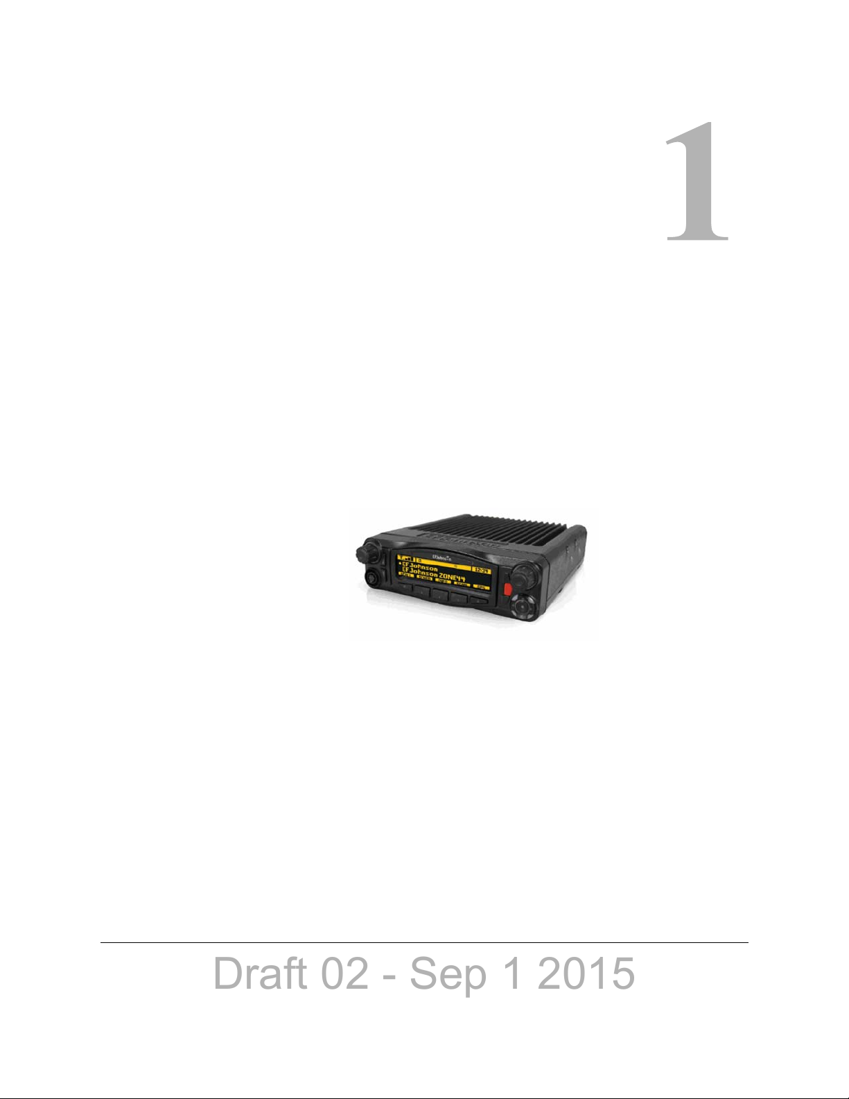
Viking Mobile Radio
Operating Manual
for the
VM600 Radio
Project 25 Conventional and Trunking
Conventional Analog and Digital
SMARTNET
®
/SmartZone
®
Part Number 002-0600-03502
September 2015
Page 2

Draft 02 - Sep 1 2015
Copyright © 2014-2015 by EF Johnson Technologies, Inc.
The EFJohnson Technologies logo, Armada™, Trunked IP25™, and Call Guard® are trademarks of
EFJohnson Technologies. All other company and/or product names used in this manual are trademarks and/
or registered trademarks of their respective manufacturers.
Information in this manual is subject to change without notice.
Viking Mobile Radio Operating Manual
September 2015
Page 3

Draft 02 - Sep 1 2015
Viking Mobile Radio Operating
Manual
September 2015
Contents
1 Radio Overview 1-1
Capabilities & Features . . . . . . . . . . . . . . . . . . . . . . . . . . . . . . . . . . . . . . . . . . . . . . . . . . . . . . . . . . 1-1
Radio Software and Configuration Programming. . . . . . . . . . . . . . . . . . . . . . . . . . . . . . . . . . . . . 1-3
Supported Software . . . . . . . . . . . . . . . . . . . . . . . . . . . . . . . . . . . . . . . . . . . . . . . . . . . . . . . . . . . . . 1-3
Available Options. . . . . . . . . . . . . . . . . . . . . . . . . . . . . . . . . . . . . . . . . . . . . . . . . . . . . . . . . . . . . . . 1-3
Licensing. . . . . . . . . . . . . . . . . . . . . . . . . . . . . . . . . . . . . . . . . . . . . . . . . . . . . . . . . . . . . . . . . . . . . . 1-5
Radio Accessories . . . . . . . . . . . . . . . . . . . . . . . . . . . . . . . . . . . . . . . . . . . . . . . . . . . . . . . . . . . . . . 1-5
Digital Keypad Microphone. . . . . . . . . . . . . . . . . . . . . . . . . . . . . . . . . . . . . . . . . . . . . . . . . . . . 1-5
Base Station Unit . . . . . . . . . . . . . . . . . . . . . . . . . . . . . . . . . . . . . . . . . . . . . . . . . . . . . . . . . . . 1-6
2 Controls & Display 2-1
Standard Control Head . . . . . . . . . . . . . . . . . . . . . . . . . . . . . . . . . . . . . . . . . . . . . . . . . . . . . . . . . . 2-1
Front Panel Controls. . . . . . . . . . . . . . . . . . . . . . . . . . . . . . . . . . . . . . . . . . . . . . . . . . . . . . . . . 2-1
Display . . . . . . . . . . . . . . . . . . . . . . . . . . . . . . . . . . . . . . . . . . . . . . . . . . . . . . . . . . . . . . . . . . . 2-3
Lightning Control Head . . . . . . . . . . . . . . . . . . . . . . . . . . . . . . . . . . . . . . . . . . . . . . . . . . . . . . . . . . 2-5
Front Panel Controls. . . . . . . . . . . . . . . . . . . . . . . . . . . . . . . . . . . . . . . . . . . . . . . . . . . . . . . . . 2-6
Display . . . . . . . . . . . . . . . . . . . . . . . . . . . . . . . . . . . . . . . . . . . . . . . . . . . . . . . . . . . . . . . . . . . 2-8
Mobile Display Modes. . . . . . . . . . . . . . . . . . . . . . . . . . . . . . . . . . . . . . . . . . . . . . . . . . . . . . . 2-10
Classic Mobile Display with Zone / Channel Indicators. . . . . . . . . . . . . . . . . . . . . . . . . 2-10
Classic Mobile Display without Zone / Channel Indicators . . . . . . . . . . . . . . . . . . . . . . 2-11
Lightning Mobile Display with Zone / Channel Indicators . . . . . . . . . . . . . . . . . . . . . . . 2-11
Lightning Mobile Display without Zone / Channel Indicators. . . . . . . . . . . . . . . . . . . . . 2-11
Rear Panel Connectors . . . . . . . . . . . . . . . . . . . . . . . . . . . . . . . . . . . . . . . . . . . . . . . . . . . . . . . . . 2-12
Dual Control Configurations . . . . . . . . . . . . . . . . . . . . . . . . . . . . . . . . . . . . . . . . . . . . . . . . . . . . . 2-13
Remote Conversion Kit 250-5300-002 . . . . . . . . . . . . . . . . . . . . . . . . . . . . . . . . . . . . . . . . . . 2-13
Remote Control Head Kit 250-5300-003. . . . . . . . . . . . . . . . . . . . . . . . . . . . . . . . . . . . . . . . . 2-14
Hardware Setup . . . . . . . . . . . . . . . . . . . . . . . . . . . . . . . . . . . . . . . . . . . . . . . . . . . . . . . . . . . 2-14
Master / Slave Programming. . . . . . . . . . . . . . . . . . . . . . . . . . . . . . . . . . . . . . . . . . . . . . . . . . 2-15
Dual Control Operation. . . . . . . . . . . . . . . . . . . . . . . . . . . . . . . . . . . . . . . . . . . . . . . . . . . . . . 2-16
Programming Dual Remote Control Configurations . . . . . . . . . . . . . . . . . . . . . . . . . . . 2-16
Power On / Off. . . . . . . . . . . . . . . . . . . . . . . . . . . . . . . . . . . . . . . . . . . . . . . . . . . . . . . . 2-16
Microphone Audio . . . . . . . . . . . . . . . . . . . . . . . . . . . . . . . . . . . . . . . . . . . . . . . . . . . . . 2-16
Viking Mobile Radio Operating Manual i
Page 4

Draft 02 - Sep 1 2015
Contents
External Speaker . . . . . . . . . . . . . . . . . . . . . . . . . . . . . . . . . . . . . . . . . . . . . . . . . . . . . . . . . . . . . . 2-17
Internal / External Speaker Programming (Standard Control Head only). . . . . . . . . . . . . . . . 2-17
3 General Operation 3-1
Basic Operation . . . . . . . . . . . . . . . . . . . . . . . . . . . . . . . . . . . . . . . . . . . . . . . . . . . . . . . . . . . . . . . . 3-1
Turning Power ON and Setting Volume . . . . . . . . . . . . . . . . . . . . . . . . . . . . . . . . . . . . . . . . . . 3-1
Setting Volume Level. . . . . . . . . . . . . . . . . . . . . . . . . . . . . . . . . . . . . . . . . . . . . . . . . . . . 3-2
Unprogrammed Tones. . . . . . . . . . . . . . . . . . . . . . . . . . . . . . . . . . . . . . . . . . . . . . . . . . . 3-2
Standard and Soft Power Down . . . . . . . . . . . . . . . . . . . . . . . . . . . . . . . . . . . . . . . . . . . 3-2
Persistent Settings . . . . . . . . . . . . . . . . . . . . . . . . . . . . . . . . . . . . . . . . . . . . . . . . . . . . . . . . . . 3-3
Power-Up Password. . . . . . . . . . . . . . . . . . . . . . . . . . . . . . . . . . . . . . . . . . . . . . . . . . . . . . . . . 3-3
Programming Passwords . . . . . . . . . . . . . . . . . . . . . . . . . . . . . . . . . . . . . . . . . . . . . . . . 3-4
Lost Passwords. . . . . . . . . . . . . . . . . . . . . . . . . . . . . . . . . . . . . . . . . . . . . . . . . . . . . . . . 3-4
Changing Passwords. . . . . . . . . . . . . . . . . . . . . . . . . . . . . . . . . . . . . . . . . . . . . . . . . . . . 3-4
Password Entry Procedure . . . . . . . . . . . . . . . . . . . . . . . . . . . . . . . . . . . . . . . . . . . . . . . 3-4
Zone Password . . . . . . . . . . . . . . . . . . . . . . . . . . . . . . . . . . . . . . . . . . . . . . . . . . . . . . . . 3-4
Speaking into the Microphone. . . . . . . . . . . . . . . . . . . . . . . . . . . . . . . . . . . . . . . . . . . . . . . . . . 3-5
Display Backlight Control . . . . . . . . . . . . . . . . . . . . . . . . . . . . . . . . . . . . . . . . . . . . . . . . . . . . . 3-5
Display Viewing Angle & Contrast Adjust (Standard Control Head Only). . . . . . . . . . . . . . . . . 3-5
Zone / Channel Display and Select. . . . . . . . . . . . . . . . . . . . . . . . . . . . . . . . . . . . . . . . . . . . . . 3-6
Zone / Channel Select . . . . . . . . . . . . . . . . . . . . . . . . . . . . . . . . . . . . . . . . . . . . . . . . . . 3-7
Direct Channel Select . . . . . . . . . . . . . . . . . . . . . . . . . . . . . . . . . . . . . . . . . . . . . . . . . . . 3-8
Setting Squelch Control . . . . . . . . . . . . . . . . . . . . . . . . . . . . . . . . . . . . . . . . . . . . . . . . . . . . . . 3-9
Zone Edit. . . . . . . . . . . . . . . . . . . . . . . . . . . . . . . . . . . . . . . . . . . . . . . . . . . . . . . . . . . . . . . . . . 3-9
Transmit Disable. . . . . . . . . . . . . . . . . . . . . . . . . . . . . . . . . . . . . . . . . . . . . . . . . . . . . . . . . . . 3-10
Operation At Extended Range . . . . . . . . . . . . . . . . . . . . . . . . . . . . . . . . . . . . . . . . . . . . . . . . 3-11
Preventing Vehicle Battery Discharge. . . . . . . . . . . . . . . . . . . . . . . . . . . . . . . . . . . . . . . . . . . 3-11
Cleaning the Control Head . . . . . . . . . . . . . . . . . . . . . . . . . . . . . . . . . . . . . . . . . . . . . . . . . . . 3-11
Radio Service . . . . . . . . . . . . . . . . . . . . . . . . . . . . . . . . . . . . . . . . . . . . . . . . . . . . . . . . . . . . . 3-12
Single Touch. . . . . . . . . . . . . . . . . . . . . . . . . . . . . . . . . . . . . . . . . . . . . . . . . . . . . . . . . . . . . . . . . . 3-12
Single Touch Buttons . . . . . . . . . . . . . . . . . . . . . . . . . . . . . . . . . . . . . . . . . . . . . . . . . . . . . . . 3-13
Detailed Single Touch Operation. . . . . . . . . . . . . . . . . . . . . . . . . . . . . . . . . . . . . . . . . . . . . . . 3-13
Conventional Unit Call. . . . . . . . . . . . . . . . . . . . . . . . . . . . . . . . . . . . . . . . . . . . . . . . . . 3-13
Conventional Call Alert . . . . . . . . . . . . . . . . . . . . . . . . . . . . . . . . . . . . . . . . . . . . . . . . . 3-14
Conventional Status . . . . . . . . . . . . . . . . . . . . . . . . . . . . . . . . . . . . . . . . . . . . . . . . . . . 3-14
Conventional Message . . . . . . . . . . . . . . . . . . . . . . . . . . . . . . . . . . . . . . . . . . . . . . . . . 3-15
P25 Unit Call . . . . . . . . . . . . . . . . . . . . . . . . . . . . . . . . . . . . . . . . . . . . . . . . . . . . . . . . . 3-15
P25 Call Alert. . . . . . . . . . . . . . . . . . . . . . . . . . . . . . . . . . . . . . . . . . . . . . . . . . . . . . . . . 3-16
P25 Status. . . . . . . . . . . . . . . . . . . . . . . . . . . . . . . . . . . . . . . . . . . . . . . . . . . . . . . . . . . 3-17
P25 Interconnect . . . . . . . . . . . . . . . . . . . . . . . . . . . . . . . . . . . . . . . . . . . . . . . . . . . . . . 3-17
SNSZ Unit Call . . . . . . . . . . . . . . . . . . . . . . . . . . . . . . . . . . . . . . . . . . . . . . . . . . . . . . . 3-17
SNSZ Call Alert . . . . . . . . . . . . . . . . . . . . . . . . . . . . . . . . . . . . . . . . . . . . . . . . . . . . . . . 3-18
SNSZ Status . . . . . . . . . . . . . . . . . . . . . . . . . . . . . . . . . . . . . . . . . . . . . . . . . . . . . . . . . 3-19
SNSZ Message: . . . . . . . . . . . . . . . . . . . . . . . . . . . . . . . . . . . . . . . . . . . . . . . . . . . . . . 3-19
SNSZ Interconnect:. . . . . . . . . . . . . . . . . . . . . . . . . . . . . . . . . . . . . . . . . . . . . . . . . . . . 3-19
Radio Inhibit . . . . . . . . . . . . . . . . . . . . . . . . . . . . . . . . . . . . . . . . . . . . . . . . . . . . . . . . . . . . . . . . . . 3-20
Setting Squelch . . . . . . . . . . . . . . . . . . . . . . . . . . . . . . . . . . . . . . . . . . . . . . . . . . . . . . . . . . . . . . . 3-20
Operating Modes . . . . . . . . . . . . . . . . . . . . . . . . . . . . . . . . . . . . . . . . . . . . . . . . . . . . . . . . . . . . . . 3-21
Conventional Mode. . . . . . . . . . . . . . . . . . . . . . . . . . . . . . . . . . . . . . . . . . . . . . . . . . . . . . . . . 3-21
ii Viking Mobile Radio Operating Manual
Page 5

Draft 02 - Sep 1 2015
SMARTNET / SmartZone Mode . . . . . . . . . . . . . . . . . . . . . . . . . . . . . . . . . . . . . . . . . . . . . . . 3-22
P25 Trunking Mode. . . . . . . . . . . . . . . . . . . . . . . . . . . . . . . . . . . . . . . . . . . . . . . . . . . . . . . . . 3-22
Systems, Channels, and Zones . . . . . . . . . . . . . . . . . . . . . . . . . . . . . . . . . . . . . . . . . . . . . . . 3-23
Systems. . . . . . . . . . . . . . . . . . . . . . . . . . . . . . . . . . . . . . . . . . . . . . . . . . . . . . . . . . . . . 3-23
Channels . . . . . . . . . . . . . . . . . . . . . . . . . . . . . . . . . . . . . . . . . . . . . . . . . . . . . . . . . . . . 3-23
Zones. . . . . . . . . . . . . . . . . . . . . . . . . . . . . . . . . . . . . . . . . . . . . . . . . . . . . . . . . . . . . . . 3-24
4 Radio Wide Features 4-1
Option Buttons . . . . . . . . . . . . . . . . . . . . . . . . . . . . . . . . . . . . . . . . . . . . . . . . . . . . . . . . . . . . . . . . . 4-1
Menu Mode . . . . . . . . . . . . . . . . . . . . . . . . . . . . . . . . . . . . . . . . . . . . . . . . . . . . . . . . . . . . . . . . . . . . 4-4
Time-Out Timer. . . . . . . . . . . . . . . . . . . . . . . . . . . . . . . . . . . . . . . . . . . . . . . . . . . . . . . . . . . . . . . . . 4-5
Home Channel Select. . . . . . . . . . . . . . . . . . . . . . . . . . . . . . . . . . . . . . . . . . . . . . . . . . . . . . . . . . . . 4-5
Power Output Select . . . . . . . . . . . . . . . . . . . . . . . . . . . . . . . . . . . . . . . . . . . . . . . . . . . . . . . . . . . . 4-6
Alert Tone Select. . . . . . . . . . . . . . . . . . . . . . . . . . . . . . . . . . . . . . . . . . . . . . . . . . . . . . . . . . . . . . . . 4-6
Ignition Power Down Duration . . . . . . . . . . . . . . . . . . . . . . . . . . . . . . . . . . . . . . . . . . . . . . . . . . . . 4-7
Contents
Horn Alert . . . . . . . . . . . . . . . . . . . . . . . . . . . . . . . . . . . . . . . . . . . . . . . . . . . . . . . . . . . . . . . . . . . . . 4-7
Microphone Off-Hook Detect. . . . . . . . . . . . . . . . . . . . . . . . . . . . . . . . . . . . . . . . . . . . . . . . . . . . . . 4-8
Surveillance Mode . . . . . . . . . . . . . . . . . . . . . . . . . . . . . . . . . . . . . . . . . . . . . . . . . . . . . . . . . . . . . . 4-8
Public Address . . . . . . . . . . . . . . . . . . . . . . . . . . . . . . . . . . . . . . . . . . . . . . . . . . . . . . . . . . . . . . . . . 4-8
Scanning . . . . . . . . . . . . . . . . . . . . . . . . . . . . . . . . . . . . . . . . . . . . . . . . . . . . . . . . . . . . . . . . . . . . . . 4-9
Priority (Standard) Scanning. . . . . . . . . . . . . . . . . . . . . . . . . . . . . . . . . . . . . . . . . . . . . . . . . . 4-10
Radio Wide Scanning . . . . . . . . . . . . . . . . . . . . . . . . . . . . . . . . . . . . . . . . . . . . . . . . . . . . . . . 4-10
Scan Hold Time. . . . . . . . . . . . . . . . . . . . . . . . . . . . . . . . . . . . . . . . . . . . . . . . . . . . . . . . . . . . 4-11
Transmitting in the Scan Mode . . . . . . . . . . . . . . . . . . . . . . . . . . . . . . . . . . . . . . . . . . . . . . . . 4-11
Nuisance Channel Delete. . . . . . . . . . . . . . . . . . . . . . . . . . . . . . . . . . . . . . . . . . . . . . . . . . . . 4-12
Scan Lists . . . . . . . . . . . . . . . . . . . . . . . . . . . . . . . . . . . . . . . . . . . . . . . . . . . . . . . . . . . . . . . . . . . . 4-12
Priority Mode Scan Lists . . . . . . . . . . . . . . . . . . . . . . . . . . . . . . . . . . . . . . . . . . . . . . . . . . . . 4-13
Determining Channels in Priority Scan List. . . . . . . . . . . . . . . . . . . . . . . . . . . . . . . . . . 4-13
Selecting a Priority Scan List. . . . . . . . . . . . . . . . . . . . . . . . . . . . . . . . . . . . . . . . . . . . . 4-13
Editing a Priority Scan List. . . . . . . . . . . . . . . . . . . . . . . . . . . . . . . . . . . . . . . . . . . . . . . 4-14
Radio Wide Scan List . . . . . . . . . . . . . . . . . . . . . . . . . . . . . . . . . . . . . . . . . . . . . . . . . . . . . . . 4-14
Determining Channels in Radio Wide Scan List . . . . . . . . . . . . . . . . . . . . . . . . . . . . . . 4-15
Editing a Radio Wide Scan List. . . . . . . . . . . . . . . . . . . . . . . . . . . . . . . . . . . . . . . . . . . 4-15
Over the Air Programming. . . . . . . . . . . . . . . . . . . . . . . . . . . . . . . . . . . . . . . . . . . . . . . . . . . . . . . 4-16
Radio Set Up. . . . . . . . . . . . . . . . . . . . . . . . . . . . . . . . . . . . . . . . . . . . . . . . . . . . . . . . . . . . . . 4-16
OTAP Transfer Times . . . . . . . . . . . . . . . . . . . . . . . . . . . . . . . . . . . . . . . . . . . . . . . . . . . . . . . 4-16
Over the Internet Programming . . . . . . . . . . . . . . . . . . . . . . . . . . . . . . . . . . . . . . . . . . . . . . . . . . 4-17
Security. . . . . . . . . . . . . . . . . . . . . . . . . . . . . . . . . . . . . . . . . . . . . . . . . . . . . . . . . . . . . . . . . . 4-17
Voice Announcements . . . . . . . . . . . . . . . . . . . . . . . . . . . . . . . . . . . . . . . . . . . . . . . . . . . . . . 4-17
Encryption. . . . . . . . . . . . . . . . . . . . . . . . . . . . . . . . . . . . . . . . . . . . . . . . . . . . . . . . . . . . . . . . 4-17
Limitations. . . . . . . . . . . . . . . . . . . . . . . . . . . . . . . . . . . . . . . . . . . . . . . . . . . . . . . . . . . . . . . . 4-17
Disconnection Events . . . . . . . . . . . . . . . . . . . . . . . . . . . . . . . . . . . . . . . . . . . . . . . . . . 4-17
Concurrent Transfers. . . . . . . . . . . . . . . . . . . . . . . . . . . . . . . . . . . . . . . . . . . . . . . . . . . 4-18
Viking Mobile Radio Operating Manual iii
Page 6

Draft 02 - Sep 1 2015
Contents
Auto / Unmute. . . . . . . . . . . . . . . . . . . . . . . . . . . . . . . . . . . . . . . . . . . . . . . . . . . . . . . . . . . . . . . . . 4-18
Location Services. . . . . . . . . . . . . . . . . . . . . . . . . . . . . . . . . . . . . . . . . . . . . . . . . . . . . . . . . . . . . . 4-18
LRRP. . . . . . . . . . . . . . . . . . . . . . . . . . . . . . . . . . . . . . . . . . . . . . . . . . . . . . . . . . . . . . . . . . . . 4-20
Triggering . . . . . . . . . . . . . . . . . . . . . . . . . . . . . . . . . . . . . . . . . . . . . . . . . . . . . . . . . . . . . . . . 4-21
Emergency Alarm Receive Indicator . . . . . . . . . . . . . . . . . . . . . . . . . . . . . . . . . . . . . . . . . . . . . . 4-22
Kiosk Mode . . . . . . . . . . . . . . . . . . . . . . . . . . . . . . . . . . . . . . . . . . . . . . . . . . . . . . . . . . . . . . . . . . . 4-23
Analog Noise Reduction . . . . . . . . . . . . . . . . . . . . . . . . . . . . . . . . . . . . . . . . . . . . . . . . . . . . . . . . 4-23
5 Conventional Mode Features 5-1
Monitoring Before Transmitting . . . . . . . . . . . . . . . . . . . . . . . . . . . . . . . . . . . . . . . . . . . . . . . . . . . 5-1
Automatic Channel Monitoring . . . . . . . . . . . . . . . . . . . . . . . . . . . . . . . . . . . . . . . . . . . . . . . . . 5-1
Manual Channel Monitoring . . . . . . . . . . . . . . . . . . . . . . . . . . . . . . . . . . . . . . . . . . . . . . . . . . . 5-1
Monitor Mode . . . . . . . . . . . . . . . . . . . . . . . . . . . . . . . . . . . . . . . . . . . . . . . . . . . . . . . . . . . . . . . . . . 5-2
Busy Channel Lockout. . . . . . . . . . . . . . . . . . . . . . . . . . . . . . . . . . . . . . . . . . . . . . . . . . . . . . . . . . . 5-3
Call Guard Squelch . . . . . . . . . . . . . . . . . . . . . . . . . . . . . . . . . . . . . . . . . . . . . . . . . . . . . . . . . . . . . 5-3
Call Guard Squelch Enable / Disable . . . . . . . . . . . . . . . . . . . . . . . . . . . . . . . . . . . . . . . . . . . . 5-4
Tone Call Guard Squelch . . . . . . . . . . . . . . . . . . . . . . . . . . . . . . . . . . . . . . . . . . . . . . . . . . . . . 5-4
Digital Call Guard Squelch . . . . . . . . . . . . . . . . . . . . . . . . . . . . . . . . . . . . . . . . . . . . . . . . . . . . 5-4
Disable Call Guard . . . . . . . . . . . . . . . . . . . . . . . . . . . . . . . . . . . . . . . . . . . . . . . . . . . . . . . . . . 5-5
Conventional Squelch Adjust . . . . . . . . . . . . . . . . . . . . . . . . . . . . . . . . . . . . . . . . . . . . . . . . . . 5-5
Selective Squelch Code Select (CTCSS / DSC / NAC) . . . . . . . . . . . . . . . . . . . . . . . . . . . . . . 5-5
Penalty Timer . . . . . . . . . . . . . . . . . . . . . . . . . . . . . . . . . . . . . . . . . . . . . . . . . . . . . . . . . . . . . . . . . . 5-6
Conversation Timer . . . . . . . . . . . . . . . . . . . . . . . . . . . . . . . . . . . . . . . . . . . . . . . . . . . . . . . . . . . . . 5-7
Repeater Talk-Around . . . . . . . . . . . . . . . . . . . . . . . . . . . . . . . . . . . . . . . . . . . . . . . . . . . . . . . . . . . 5-7
Displaying Transmit / Receive Frequency . . . . . . . . . . . . . . . . . . . . . . . . . . . . . . . . . . . . . . . . . . . 5-7
Emergency Alarm and Call . . . . . . . . . . . . . . . . . . . . . . . . . . . . . . . . . . . . . . . . . . . . . . . . . . . . . . . 5-8
Emergency Alarms . . . . . . . . . . . . . . . . . . . . . . . . . . . . . . . . . . . . . . . . . . . . . . . . . . . . . . . . . . 5-8
Emergency Call Alert . . . . . . . . . . . . . . . . . . . . . . . . . . . . . . . . . . . . . . . . . . . . . . . . . . . . . . . . 5-9
Emergency Calls. . . . . . . . . . . . . . . . . . . . . . . . . . . . . . . . . . . . . . . . . . . . . . . . . . . . . . . . . . . . 5-9
Emergency Hot Mic. . . . . . . . . . . . . . . . . . . . . . . . . . . . . . . . . . . . . . . . . . . . . . . . . . . . 5-10
Placing an Emergency Call . . . . . . . . . . . . . . . . . . . . . . . . . . . . . . . . . . . . . . . . . . . . . . 5-10
Emergency Press and Hold . . . . . . . . . . . . . . . . . . . . . . . . . . . . . . . . . . . . . . . . . . . . . . . . . . 5-10
Emergency Talkgroup. . . . . . . . . . . . . . . . . . . . . . . . . . . . . . . . . . . . . . . . . . . . . . . . . . . . . . . 5-11
Conventional Mode Channel Scanning . . . . . . . . . . . . . . . . . . . . . . . . . . . . . . . . . . . . . . . . . . . . 5-11
Selecting a Scan List. . . . . . . . . . . . . . . . . . . . . . . . . . . . . . . . . . . . . . . . . . . . . . . . . . . . . . . . 5-11
Conventional Scan List Select Procedure. . . . . . . . . . . . . . . . . . . . . . . . . . . . . . . . . . . 5-11
Transmitting in Scan Mode . . . . . . . . . . . . . . . . . . . . . . . . . . . . . . . . . . . . . . . . . . . . . . . . . . . 5-12
Priority Channel Sampling. . . . . . . . . . . . . . . . . . . . . . . . . . . . . . . . . . . . . . . . . . . . . . . . . . . . 5-12
Changing The Priority Channel . . . . . . . . . . . . . . . . . . . . . . . . . . . . . . . . . . . . . . . . . . . 5-14
Talkgroup Scanning. . . . . . . . . . . . . . . . . . . . . . . . . . . . . . . . . . . . . . . . . . . . . . . . . . . . . . . . . 5-14
Standard Conventional Calls. . . . . . . . . . . . . . . . . . . . . . . . . . . . . . . . . . . . . . . . . . . . . . . . . . . . . 5-15
Placing a Standard Conventional Call. . . . . . . . . . . . . . . . . . . . . . . . . . . . . . . . . . . . . . . . . . . 5-16
Receiving a Standard Conventional Call. . . . . . . . . . . . . . . . . . . . . . . . . . . . . . . . . . . . . . . . . 5-16
iv Viking Mobile Radio Operating Manual
Page 7

Draft 02 - Sep 1 2015
DTMF / ANI Signaling. . . . . . . . . . . . . . . . . . . . . . . . . . . . . . . . . . . . . . . . . . . . . . . . . . . . . . . . . . . 5-16
Single Tone Encoder. . . . . . . . . . . . . . . . . . . . . . . . . . . . . . . . . . . . . . . . . . . . . . . . . . . . . . . . 5-17
Two Tone Encoder . . . . . . . . . . . . . . . . . . . . . . . . . . . . . . . . . . . . . . . . . . . . . . . . . . . . . . . . . 5-17
Two Tone Decoder . . . . . . . . . . . . . . . . . . . . . . . . . . . . . . . . . . . . . . . . . . . . . . . . . . . . . . . . . 5-18
Five Tone Encoder . . . . . . . . . . . . . . . . . . . . . . . . . . . . . . . . . . . . . . . . . . . . . . . . . . . . . . . . . 5-18
MDC1200 Compatibility . . . . . . . . . . . . . . . . . . . . . . . . . . . . . . . . . . . . . . . . . . . . . . . . . . . . . 5-18
GE Star. . . . . . . . . . . . . . . . . . . . . . . . . . . . . . . . . . . . . . . . . . . . . . . . . . . . . . . . . . . . . . . . . . 5-19
Project 25 Mode Features . . . . . . . . . . . . . . . . . . . . . . . . . . . . . . . . . . . . . . . . . . . . . . . . . . . . . . . 5-19
Digital Unit ID . . . . . . . . . . . . . . . . . . . . . . . . . . . . . . . . . . . . . . . . . . . . . . . . . . . . . . . . . . . . . 5-19
Talkgroup ID . . . . . . . . . . . . . . . . . . . . . . . . . . . . . . . . . . . . . . . . . . . . . . . . . . . . . . . . . . . . . . 5-19
Network Access Code (NAC) . . . . . . . . . . . . . . . . . . . . . . . . . . . . . . . . . . . . . . . . . . . . . . . . . 5-20
EFJohnson System Out-of-Range Indicator. . . . . . . . . . . . . . . . . . . . . . . . . . . . . . . . . . . . . . 5-20
EFJohnson System Automatic Registration . . . . . . . . . . . . . . . . . . . . . . . . . . . . . . . . . . . . . . 5-21
P25 Group Calls . . . . . . . . . . . . . . . . . . . . . . . . . . . . . . . . . . . . . . . . . . . . . . . . . . . . . . . . . . . 5-21
Changing Talkgroup Assigned To a Channel. . . . . . . . . . . . . . . . . . . . . . . . . . . . . . . . . 5-22
P25 Unit Calls. . . . . . . . . . . . . . . . . . . . . . . . . . . . . . . . . . . . . . . . . . . . . . . . . . . . . . . . . . . . . 5-22
Place and Receive a Unit Call. . . . . . . . . . . . . . . . . . . . . . . . . . . . . . . . . . . . . . . . . . . . 5-22
Direct Channel Entry . . . . . . . . . . . . . . . . . . . . . . . . . . . . . . . . . . . . . . . . . . . . . . . . . . . 5-23
P25 Conventional Telephone Calls. . . . . . . . . . . . . . . . . . . . . . . . . . . . . . . . . . . . . . . . . . . . . 5-24
Access / De-Access Codes. . . . . . . . . . . . . . . . . . . . . . . . . . . . . . . . . . . . . . . . . . . . . . 5-24
Placing a Telephone Call. . . . . . . . . . . . . . . . . . . . . . . . . . . . . . . . . . . . . . . . . . . . . . . . 5-24
Answering a Telephone Call . . . . . . . . . . . . . . . . . . . . . . . . . . . . . . . . . . . . . . . . . . . . . 5-25
Call Alert . . . . . . . . . . . . . . . . . . . . . . . . . . . . . . . . . . . . . . . . . . . . . . . . . . . . . . . . . . . . . . . . . 5-26
Call History . . . . . . . . . . . . . . . . . . . . . . . . . . . . . . . . . . . . . . . . . . . . . . . . . . . . . . . . . . . . . . . 5-27
Messaging. . . . . . . . . . . . . . . . . . . . . . . . . . . . . . . . . . . . . . . . . . . . . . . . . . . . . . . . . . . . . . . . 5-27
Status Messaging . . . . . . . . . . . . . . . . . . . . . . . . . . . . . . . . . . . . . . . . . . . . . . . . . . . . . . . . . . 5-28
P25 Packet Data. . . . . . . . . . . . . . . . . . . . . . . . . . . . . . . . . . . . . . . . . . . . . . . . . . . . . . . . . . . 5-28
Contents
Keypad Programming . . . . . . . . . . . . . . . . . . . . . . . . . . . . . . . . . . . . . . . . . . . . . . . . . . . . . . . . . . 5-28
Menu Structure . . . . . . . . . . . . . . . . . . . . . . . . . . . . . . . . . . . . . . . . . . . . . . . . . . . . . . . . . . . . 5-29
Zone Password. . . . . . . . . . . . . . . . . . . . . . . . . . . . . . . . . . . . . . . . . . . . . . . . . . . . . . . . . . . . 5-30
Zone Change Parameter. . . . . . . . . . . . . . . . . . . . . . . . . . . . . . . . . . . . . . . . . . . . . . . . . . . . . 5-31
Channel Change Parameter. . . . . . . . . . . . . . . . . . . . . . . . . . . . . . . . . . . . . . . . . . . . . . . . . . 5-31
System Parameters. . . . . . . . . . . . . . . . . . . . . . . . . . . . . . . . . . . . . . . . . . . . . . . . . . . . . . . . . 5-31
Channel Parameters. . . . . . . . . . . . . . . . . . . . . . . . . . . . . . . . . . . . . . . . . . . . . . . . . . . . . . . . 5-32
Text Messaging. . . . . . . . . . . . . . . . . . . . . . . . . . . . . . . . . . . . . . . . . . . . . . . . . . . . . . . . . . . . . . . . 5-34
Data Setup for Text Messaging. . . . . . . . . . . . . . . . . . . . . . . . . . . . . . . . . . . . . . . . . . . . . . . . 5-34
Receiving a Text Message . . . . . . . . . . . . . . . . . . . . . . . . . . . . . . . . . . . . . . . . . . . . . . . . . . . 5-35
Viewing Previously Received Messages. . . . . . . . . . . . . . . . . . . . . . . . . . . . . . . . . . . . . . . . . 5-35
6 SMARTNET / SmartZone / P25 Trunked Features 6-1
Analog and Digital Operation . . . . . . . . . . . . . . . . . . . . . . . . . . . . . . . . . . . . . . . . . . . . . . . . . . . . . 6-1
Viewing Unit ID . . . . . . . . . . . . . . . . . . . . . . . . . . . . . . . . . . . . . . . . . . . . . . . . . . . . . . . . . . . . . . . . . 6-1
Radio Info Button . . . . . . . . . . . . . . . . . . . . . . . . . . . . . . . . . . . . . . . . . . . . . . . . . . . . . . . . . . . 6-2
Standard Group Calls. . . . . . . . . . . . . . . . . . . . . . . . . . . . . . . . . . . . . . . . . . . . . . . . . . . . . . . . . . . . 6-2
Placing a Standard Group Call . . . . . . . . . . . . . . . . . . . . . . . . . . . . . . . . . . . . . . . . . . . . . . . . . 6-2
Receiving a Standard Group Call . . . . . . . . . . . . . . . . . . . . . . . . . . . . . . . . . . . . . . . . . . . . . . . 6-3
Unit Calls. . . . . . . . . . . . . . . . . . . . . . . . . . . . . . . . . . . . . . . . . . . . . . . . . . . . . . . . . . . . . . . . . . . . . . 6-4
Placing an Enhanced Unit Call . . . . . . . . . . . . . . . . . . . . . . . . . . . . . . . . . . . . . . . . . . . . . . . . . 6-4
Placing a Standard Unit Conversation Call. . . . . . . . . . . . . . . . . . . . . . . . . . . . . . . . . . . . . . . . 6-5
Viking Mobile Radio Operating Manual v
Page 8

Draft 02 - Sep 1 2015
Contents
Receiving a Unit Call (All Types). . . . . . . . . . . . . . . . . . . . . . . . . . . . . . . . . . . . . . . . . . . . . . . . 6-7
Telephone Calls . . . . . . . . . . . . . . . . . . . . . . . . . . . . . . . . . . . . . . . . . . . . . . . . . . . . . . . . . . . . . . . . 6-7
Placing a Telephone Call. . . . . . . . . . . . . . . . . . . . . . . . . . . . . . . . . . . . . . . . . . . . . . . . . . . . . . 6-8
Receiving A Telephone Call . . . . . . . . . . . . . . . . . . . . . . . . . . . . . . . . . . . . . . . . . . . . . . . . . . . 6-9
Call Alert . . . . . . . . . . . . . . . . . . . . . . . . . . . . . . . . . . . . . . . . . . . . . . . . . . . . . . . . . . . . . . . . . . . . . . 6-9
Answering a Page. . . . . . . . . . . . . . . . . . . . . . . . . . . . . . . . . . . . . . . . . . . . . . . . . . . . . . . . . . 6-10
Initiating a Page . . . . . . . . . . . . . . . . . . . . . . . . . . . . . . . . . . . . . . . . . . . . . . . . . . . . . . . . . . . 6-10
Messaging. . . . . . . . . . . . . . . . . . . . . . . . . . . . . . . . . . . . . . . . . . . . . . . . . . . . . . . . . . . . . . . . . . . . 6-12
P25 Messaging. . . . . . . . . . . . . . . . . . . . . . . . . . . . . . . . . . . . . . . . . . . . . . . . . . . . . . . . . . . . 6-12
Sending Status Conditions . . . . . . . . . . . . . . . . . . . . . . . . . . . . . . . . . . . . . . . . . . . . . . . . . . . . . . 6-13
Emergency Alarm and Call . . . . . . . . . . . . . . . . . . . . . . . . . . . . . . . . . . . . . . . . . . . . . . . . . . . . . . 6-14
Emergency Alarms . . . . . . . . . . . . . . . . . . . . . . . . . . . . . . . . . . . . . . . . . . . . . . . . . . . . . . . . . 6-14
Emergency Call Alert . . . . . . . . . . . . . . . . . . . . . . . . . . . . . . . . . . . . . . . . . . . . . . . . . . . . . . . 6-15
Emergency Calls. . . . . . . . . . . . . . . . . . . . . . . . . . . . . . . . . . . . . . . . . . . . . . . . . . . . . . . . . . . 6-15
Emergency Hot Mic. . . . . . . . . . . . . . . . . . . . . . . . . . . . . . . . . . . . . . . . . . . . . . . . . . . . 6-15
Placing an Emergency Call . . . . . . . . . . . . . . . . . . . . . . . . . . . . . . . . . . . . . . . . . . . . . . 6-16
Emergency Press and Hold . . . . . . . . . . . . . . . . . . . . . . . . . . . . . . . . . . . . . . . . . . . . . . . . . . 6-16
Failsoft Operation. . . . . . . . . . . . . . . . . . . . . . . . . . . . . . . . . . . . . . . . . . . . . . . . . . . . . . . . . . . . . . 6-17
Programmable Failsoft Connect Tone. . . . . . . . . . . . . . . . . . . . . . . . . . . . . . . . . . . . . . . . . . . 6-17
SMARTNET / SmartZone / P25 Trunking Scanning Features. . . . . . . . . . . . . . . . . . . . . . . . . . . 6-17
Priority Talkgroup Sampling . . . . . . . . . . . . . . . . . . . . . . . . . . . . . . . . . . . . . . . . . . . . . . . . . . 6-19
Scan List Editing and Selection. . . . . . . . . . . . . . . . . . . . . . . . . . . . . . . . . . . . . . . . . . . . . . . . 6-19
Dynamic Regrouping . . . . . . . . . . . . . . . . . . . . . . . . . . . . . . . . . . . . . . . . . . . . . . . . . . . . . . . . . . . 6-20
P25 Radio Unit Monitor . . . . . . . . . . . . . . . . . . . . . . . . . . . . . . . . . . . . . . . . . . . . . . . . . . . . . . . . . 6-21
SmartZone and P25 Trunking Unique Features. . . . . . . . . . . . . . . . . . . . . . . . . . . . . . . . . . . . . . 6-21
Busy Override. . . . . . . . . . . . . . . . . . . . . . . . . . . . . . . . . . . . . . . . . . . . . . . . . . . . . . . . . . . . . 6-22
Site Trunking. . . . . . . . . . . . . . . . . . . . . . . . . . . . . . . . . . . . . . . . . . . . . . . . . . . . . . . . . . . . . . 6-22
Determining Current Site and Searching for a New Site. . . . . . . . . . . . . . . . . . . . . . . . . . . . . 6-22
Locking / Unlocking a Site. . . . . . . . . . . . . . . . . . . . . . . . . . . . . . . . . . . . . . . . . . . . . . . . . . . . 6-23
Auto Site Search. . . . . . . . . . . . . . . . . . . . . . . . . . . . . . . . . . . . . . . . . . . . . . . . . . . . . . . . . . . 6-23
P25 Wide Area Scan. . . . . . . . . . . . . . . . . . . . . . . . . . . . . . . . . . . . . . . . . . . . . . . . . . . . . . . . 6-23
Normal P25 and SmartZone Control Channel Hunt . . . . . . . . . . . . . . . . . . . . . . . . . . . . . . . . 6-24
Talkgroup Steering through System Access Permissions. . . . . . . . . . . . . . . . . . . . . . . . . . . . 6-24
Radio Information . . . . . . . . . . . . . . . . . . . . . . . . . . . . . . . . . . . . . . . . . . . . . . . . . . . . . . . . . . 6-25
Current Software version in the radio . . . . . . . . . . . . . . . . . . . . . . . . . . . . . . . . . . . . . . . . . . . 6-25
P25 Trunking System Single Touch . . . . . . . . . . . . . . . . . . . . . . . . . . . . . . . . . . . . . . . . . . . . . . . 6-26
P25 Messaging . . . . . . . . . . . . . . . . . . . . . . . . . . . . . . . . . . . . . . . . . . . . . . . . . . . . . . . . . . . . . . . . 6-26
Sending a Message . . . . . . . . . . . . . . . . . . . . . . . . . . . . . . . . . . . . . . . . . . . . . . . . . . . . . . . . 6-27
Receiving a Message . . . . . . . . . . . . . . . . . . . . . . . . . . . . . . . . . . . . . . . . . . . . . . . . . . . . . . . 6-27
7 Secure Communication (Encryption) 7-1
Encryption Algorithms. . . . . . . . . . . . . . . . . . . . . . . . . . . . . . . . . . . . . . . . . . . . . . . . . . . . . . . . . . . 7-1
Encryption Available With Various Channel Types . . . . . . . . . . . . . . . . . . . . . . . . . . . . . . . . . . 7-1
AES. . . . . . . . . . . . . . . . . . . . . . . . . . . . . . . . . . . . . . . . . . . . . . . . . . . . . . . . . . . . . . . . . . . . . . 7-2
ARC4. . . . . . . . . . . . . . . . . . . . . . . . . . . . . . . . . . . . . . . . . . . . . . . . . . . . . . . . . . . . . . . . . . . . . 7-2
vi Viking Mobile Radio Operating Manual
Page 9

Draft 02 - Sep 1 2015
Encryption Available with Various Channel Types . . . . . . . . . . . . . . . . . . . . . . . . . . . . . . . . . . 7-2
FIPS and Non-FIPS Modes. . . . . . . . . . . . . . . . . . . . . . . . . . . . . . . . . . . . . . . . . . . . . . . . . . . . 7-2
Authentication without Encryption Options . . . . . . . . . . . . . . . . . . . . . . . . . . . . . . . . . . . . . . . . 7-2
Encryption Keys. . . . . . . . . . . . . . . . . . . . . . . . . . . . . . . . . . . . . . . . . . . . . . . . . . . . . . . . . . . . . . . . 7-3
Key and Algorithm IDs . . . . . . . . . . . . . . . . . . . . . . . . . . . . . . . . . . . . . . . . . . . . . . . . . . . . . . . 7-3
PID / SLN Key Management Modes. . . . . . . . . . . . . . . . . . . . . . . . . . . . . . . . . . . . . . . . . . . . . 7-4
Maintaining Keys in Memory. . . . . . . . . . . . . . . . . . . . . . . . . . . . . . . . . . . . . . . . . . . . . . . . . . . 7-5
Encryption Key Select. . . . . . . . . . . . . . . . . . . . . . . . . . . . . . . . . . . . . . . . . . . . . . . . . . . . . . . . 7-5
Encryption Key Erase . . . . . . . . . . . . . . . . . . . . . . . . . . . . . . . . . . . . . . . . . . . . . . . . . . . . . . . . 7-5
Encryption Icon Operation. . . . . . . . . . . . . . . . . . . . . . . . . . . . . . . . . . . . . . . . . . . . . . . . . . . . . 7-6
Clear / Secure Strapping . . . . . . . . . . . . . . . . . . . . . . . . . . . . . . . . . . . . . . . . . . . . . . . . . . . . . . . . . 7-6
Transmit Mode Options. . . . . . . . . . . . . . . . . . . . . . . . . . . . . . . . . . . . . . . . . . . . . . . . . . . . . . . 7-6
Security Settings Override . . . . . . . . . . . . . . . . . . . . . . . . . . . . . . . . . . . . . . . . . . . . . . . . . . . . . . . 7-7
P25 Conventional and Trunking Talkgroup Security Override. . . . . . . . . . . . . . . . . . . . . . . . . . 7-7
Secure Call Behavior . . . . . . . . . . . . . . . . . . . . . . . . . . . . . . . . . . . . . . . . . . . . . . . . . . . . . . . . 7-7
Failsoft, Group Regroup or Dynamic Regroup Call. . . . . . . . . . . . . . . . . . . . . . . . . . . . . 7-7
Channel with Talkgroup Specified . . . . . . . . . . . . . . . . . . . . . . . . . . . . . . . . . . . . . . . . . . 7-8
Channel with Announcement Group Specified . . . . . . . . . . . . . . . . . . . . . . . . . . . . . . . . 7-8
Announcement Group Call . . . . . . . . . . . . . . . . . . . . . . . . . . . . . . . . . . . . . . . . . . . . . . . 7-8
Emergency Calls on Emergency Groups. . . . . . . . . . . . . . . . . . . . . . . . . . . . . . . . . . . . . 7-8
Contents
Over-the-Air Rekeying (OTAR) . . . . . . . . . . . . . . . . . . . . . . . . . . . . . . . . . . . . . . . . . . . . . . . . . . . . 7-8
Radio Setup for Encryption. . . . . . . . . . . . . . . . . . . . . . . . . . . . . . . . . . . . . . . . . . . . . . . . . . . . . . . 7-9
Programming by Keyloader. . . . . . . . . . . . . . . . . . . . . . . . . . . . . . . . . . . . . . . . . . . . . . . . . . . 7-10
Radio OTAR Capabilities . . . . . . . . . . . . . . . . . . . . . . . . . . . . . . . . . . . . . . . . . . . . . . . . . . . . 7-10
OTAR Option Switches. . . . . . . . . . . . . . . . . . . . . . . . . . . . . . . . . . . . . . . . . . . . . . . . . . . . . . 7-10
P25 Trunking Icons. . . . . . . . . . . . . . . . . . . . . . . . . . . . . . . . . . . . . . . . . . . . . . . . . . . . . . . . . 7-11
8 Data Features 8-1
P25 Packet Data . . . . . . . . . . . . . . . . . . . . . . . . . . . . . . . . . . . . . . . . . . . . . . . . . . . . . . . . . . . . . . . . 8-1
P25 Trunking Data Services . . . . . . . . . . . . . . . . . . . . . . . . . . . . . . . . . . . . . . . . . . . . . . . . . . . . . . 8-2
Radio Configuration . . . . . . . . . . . . . . . . . . . . . . . . . . . . . . . . . . . . . . . . . . . . . . . . . . . . . . . . . 8-2
Interface Connection. . . . . . . . . . . . . . . . . . . . . . . . . . . . . . . . . . . . . . . . . . . . . . . . . . . . . . . . . 8-3
Context Activation. . . . . . . . . . . . . . . . . . . . . . . . . . . . . . . . . . . . . . . . . . . . . . . . . . . . . . . . . . . 8-3
PPP Link Establishment . . . . . . . . . . . . . . . . . . . . . . . . . . . . . . . . . . . . . . . . . . . . . . . . . . . . . . 8-4
Connection and Testing. . . . . . . . . . . . . . . . . . . . . . . . . . . . . . . . . . . . . . . . . . . . . . . . . 8-20
Viking Mobile Radio Operating Manual vii
Page 10

Draft 02 - Sep 1 2015
Contents
9 Tones & Error Messages 9-1
Supervisory Tones . . . . . . . . . . . . . . . . . . . . . . . . . . . . . . . . . . . . . . . . . . . . . . . . . . . . . . . . . . . . . . 9-1
Error Messages. . . . . . . . . . . . . . . . . . . . . . . . . . . . . . . . . . . . . . . . . . . . . . . . . . . . . . . . . . . . . . . . . 9-3
Viking LED Failure Codes . . . . . . . . . . . . . . . . . . . . . . . . . . . . . . . . . . . . . . . . . . . . . . . . . . . . . . . . 9-8
SZ System Reject Messages. . . . . . . . . . . . . . . . . . . . . . . . . . . . . . . . . . . . . . . . . . . . . . . . . . . . . . 9-9
10 Service Information 10-1
Product Warranty . . . . . . . . . . . . . . . . . . . . . . . . . . . . . . . . . . . . . . . . . . . . . . . . . . . . . . . . . . . . . . 10-1
Online Registration . . . . . . . . . . . . . . . . . . . . . . . . . . . . . . . . . . . . . . . . . . . . . . . . . . . . . . . . . 10-1
Telephone Technical Support . . . . . . . . . . . . . . . . . . . . . . . . . . . . . . . . . . . . . . . . . . . . . . . . . . . . 10-2
BEFORE Contacting Technical Support . . . . . . . . . . . . . . . . . . . . . . . . . . . . . . . . . . . . . . . . . 10-2
Factory Customer Service. . . . . . . . . . . . . . . . . . . . . . . . . . . . . . . . . . . . . . . . . . . . . . . . . . . . . . . 10-2
Returns for Repairs . . . . . . . . . . . . . . . . . . . . . . . . . . . . . . . . . . . . . . . . . . . . . . . . . . . . . . . . . . . . 10-3
Replacement Parts. . . . . . . . . . . . . . . . . . . . . . . . . . . . . . . . . . . . . . . . . . . . . . . . . . . . . . . . . . . . . 10-4
Internet Home Page . . . . . . . . . . . . . . . . . . . . . . . . . . . . . . . . . . . . . . . . . . . . . . . . . . . . . . . . . . . . 10-4
viii Viking Mobile Radio Operating Manual
Page 11

Draft 02 - Sep 1 2015
List of Figures
1.1 Viking Mobile Radio (Lightning Control Head) . . . . . . . . . . . . . . . . . . . . . . . . . . . . . . . . 1-1
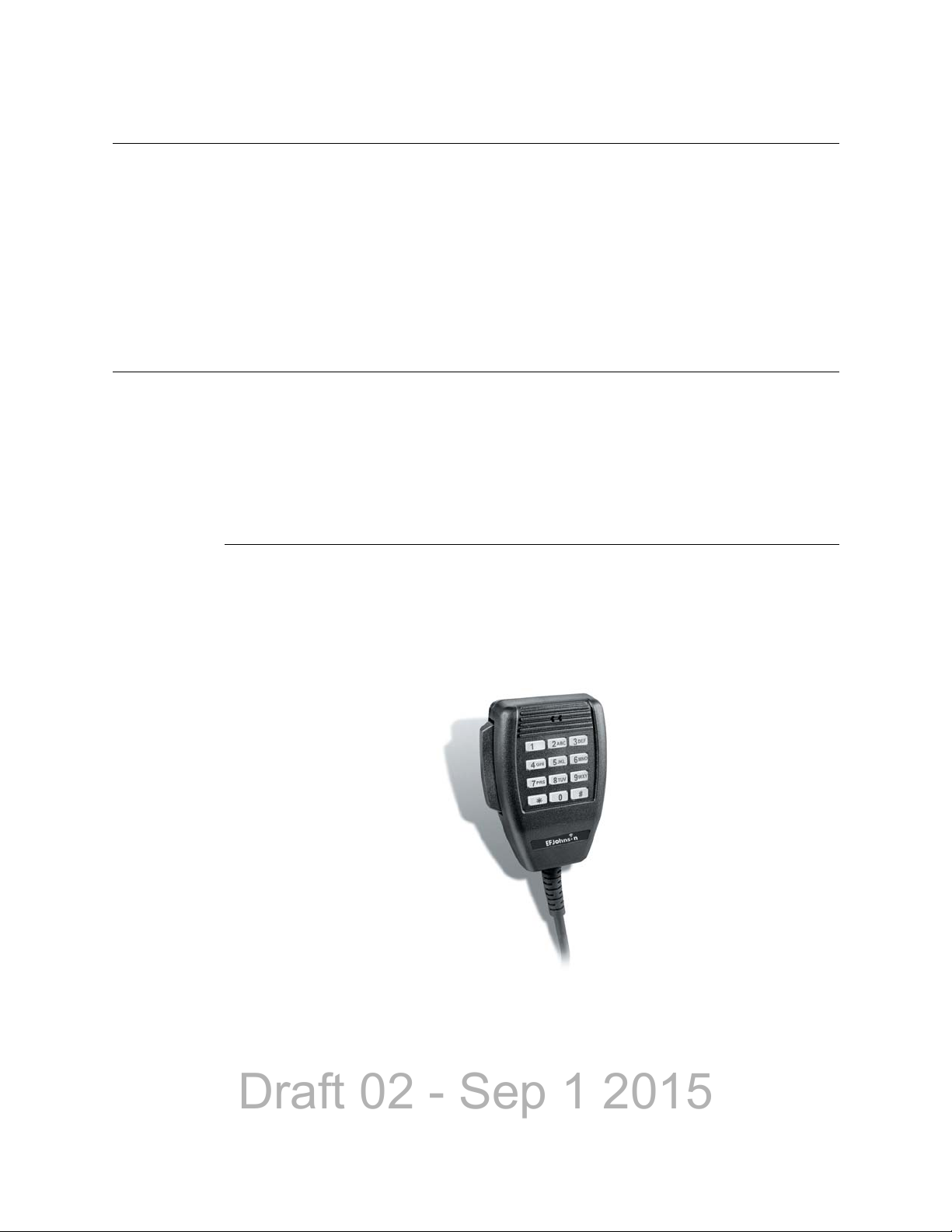
1.2 Digital Keypad Microphone . . . . . . . . . . . . . . . . . . . . . . . . . . . . . . . . . . . . . . . . . . . . . . . 1-5
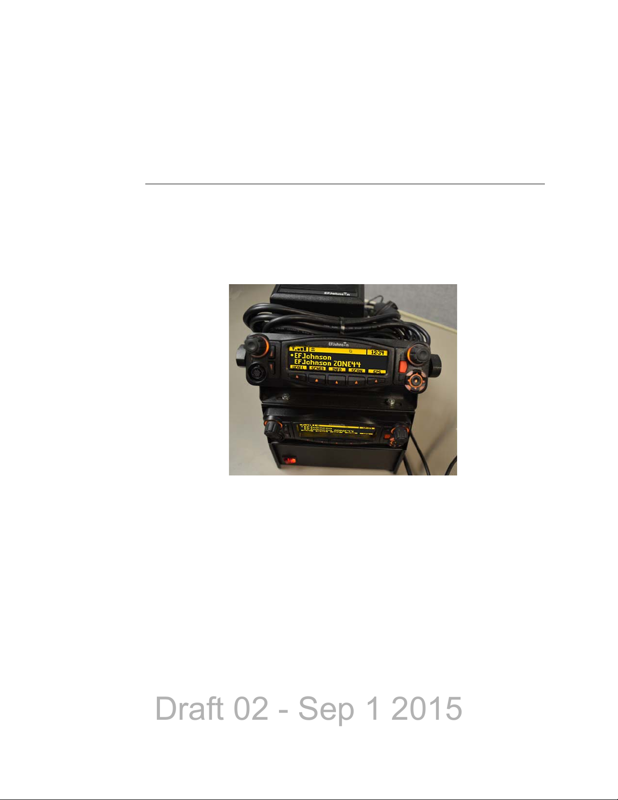
1.3 Viking Mobile Radio mounted in Base Station . . . . . . . . . . . . . . . . . . . . . . . . . . . . . . . . 1-6
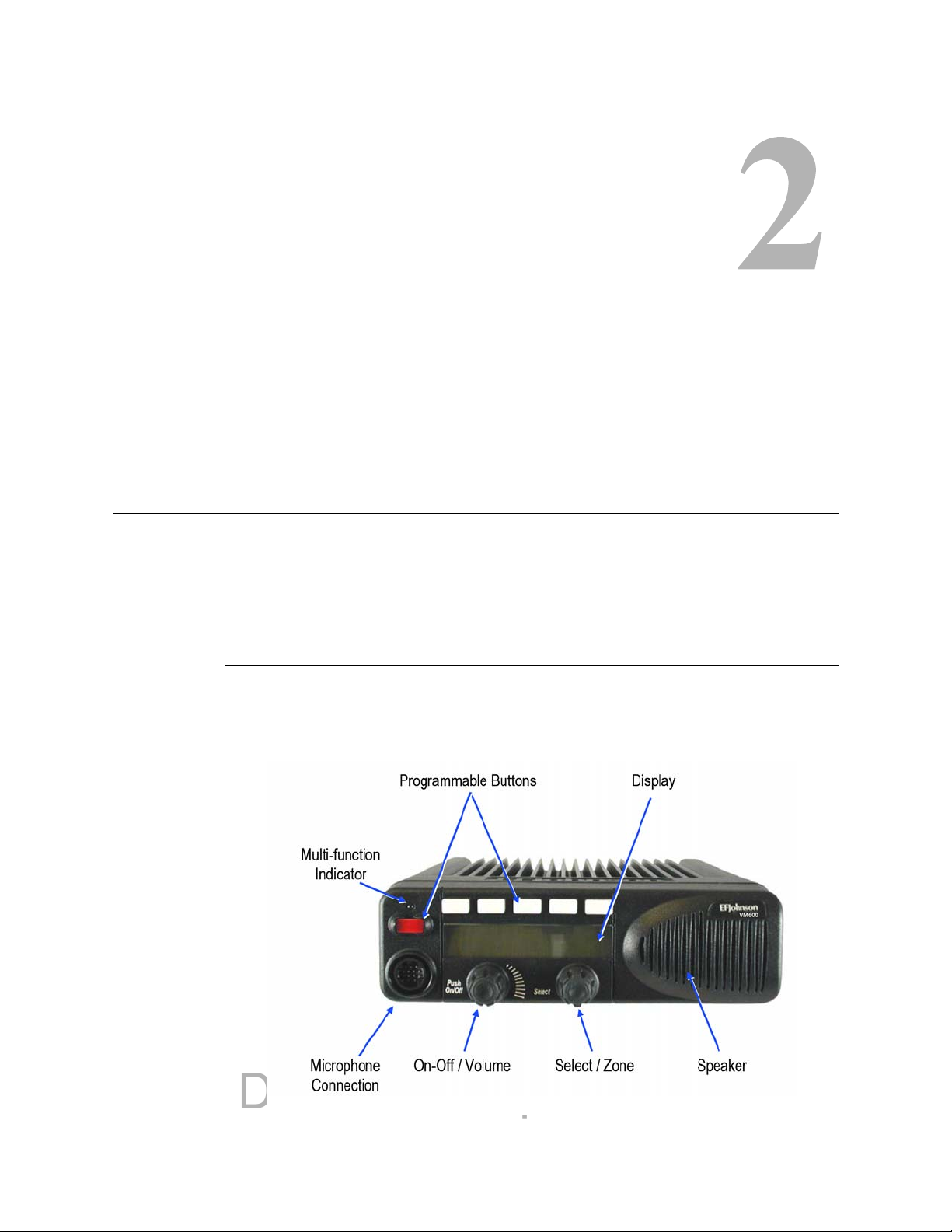
2.1 Front Panel Controls . . . . . . . . . . . . . . . . . . . . . . . . . . . . . . . . . . . . . . . . . . . . . . . . . . . . 2-1
2.2 Option Buttons . . . . . . . . . . . . . . . . . . . . . . . . . . . . . . . . . . . . . . . . . . . . . . . . . . . . . . . . 2-2
2.3 Front Panel Display . . . . . . . . . . . . . . . . . . . . . . . . . . . . . . . . . . . . . . . . . . . . . . . . . . . . . 2-3
2.4 Radio with Lightning Control Head . . . . . . . . . . . . . . . . . . . . . . . . . . . . . . . . . . . . . . . . . 2-5
2.5 Lightning Control Head Controls . . . . . . . . . . . . . . . . . . . . . . . . . . . . . . . . . . . . . . . . . . . 2-6
2.6 Lightning Option Buttons . . . . . . . . . . . . . . . . . . . . . . . . . . . . . . . . . . . . . . . . . . . . . . . . . 2-7
2.7 Lightning Control Head Display . . . . . . . . . . . . . . . . . . . . . . . . . . . . . . . . . . . . . . . . . . . 2-8
2.8 Classic Mobile Display with Zone and Channel Indicators . . . . . . . . . . . . . . . . . . . . . 2-10
2.9 Classic Mobile Display without Zone and Channel Indicato rs . . . . . . . . . . . . . . . . . . . 2-11
2.10 Lightning Mobile Display with Zone and Channel Indicators . . . . . . . . . . . . . . . . . . . . 2-11
2.11 Lightning Mobile Display wi thout Zone and Channel Indicato rs . . . . . . . . . . . . . . . . . 2-12
2.12 Rear Panel Connectors . . . . . . . . . . . . . . . . . . . . . . . . . . . . . . . . . . . . . . . . . . . . . . . . . 2-12
2.13 Dash-Mount Radio with Remote Control Head . . . . . . . . . . . . . . . . . . . . . . . . . . . . . . . 2-13
2.14 Remote-Mount Radio with Two Remote Control Heads . . . . . . . . . . . . . . . . . . . . . . . . 2-13
2.15 Control Head Option Buttons . . . . . . . . . . . . . . . . . . . . . . . . . . . . . . . . . . . . . . . . . . . . 2-15
2.16 EFJohnson External Speaker . . . . . . . . . . . . . . . . . . . . . . . . . . . . . . . . . . . . . . . . . . . . 2-17
3.1 Zone Display . . . . . . . . . . . . . . . . . . . . . . . . . . . . . . . . . . . . . . . . . . . . . . . . . . . . . . . . . . 3-6
3.2 Channel Display . . . . . . . . . . . . . . . . . . . . . . . . . . . . . . . . . . . . . . . . . . . . . . . . . . . . . . . 3-7
4.1 Option Buttons . . . . . . . . . . . . . . . . . . . . . . . . . . . . . . . . . . . . . . . . . . . . . . . . . . . . . . . . 4-1
4.2 GPS Icon . . . . . . . . . . . . . . . . . . . . . . . . . . . . . . . . . . . . . . . . . . . . . . . . . . . . . . . . . . . . 4-20
5.1 Viking Keypad Programming Menu Flowchart . . . . . . . . . . . . . . . . . . . . . . . . . . . . . . . 5-30
7.1 Key Selection Example . . . . . . . . . . . . . . . . . . . . . . . . . . . . . . . . . . . . . . . . . . . . . . . . . . 7-4
8.1 Network Connection Screen . . . . . . . . . . . . . . . . . . . . . . . . . . . . . . . . . . . . . . . . . . . . . . 8-4
8.2 New Connection Wizard Screen . . . . . . . . . . . . . . . . . . . . . . . . . . . . . . . . . . . . . . . . . . . 8-5
8.3 Network Connection Type Screen . . . . . . . . . . . . . . . . . . . . . . . . . . . . . . . . . . . . . . . . . 8-6
8.4 Advanced Connection Options Screen . . . . . . . . . . . . . . . . . . . . . . . . . . . . . . . . . . . . . . 8-7
8.5 Host or Guest Screen . . . . . . . . . . . . . . . . . . . . . . . . . . . . . . . . . . . . . . . . . . . . . . . . . . . 8-8
8.6 Connection Name Screen . . . . . . . . . . . . . . . . . . . . . . . . . . . . . . . . . . . . . . . . . . . . . . . . 8-9
8.7 Select a Device Screen . . . . . . . . . . . . . . . . . . . . . . . . . . . . . . . . . . . . . . . . . . . . . . . . . 8-10
8.8 Connection Availability . . . . . . . . . . . . . . . . . . . . . . . . . . . . . . . . . . . . . . . . . . . . . . . . . 8-11
8.9 Completing New Connection Wizard Screen . . . . . . . . . . . . . . . . . . . . . . . . . . . . . . . . 8-11
8.10 Connect Radio Screen . . . . . . . . . . . . . . . . . . . . . . . . . . . . . . . . . . . . . . . . . . . . . . . . . 8-12
8.11 Radio Properties Screen: General Tab . . . . . . . . . . . . . . . . . . . . . . . . . . . . . . . . . . . . . 8-13
8.12 Modem Configuration Screen . . . . . . . . . . . . . . . . . . . . . . . . . . . . . . . . . . . . . . . . . . . . 8-14
8.13 Radio Properties Screen: Options Tab . . . . . . . . . . . . . . . . . . . . . . . . . . . . . . . . . . . . . 8-15
8.14 Radio Properties Screen: Networking Tab . . . . . . . . . . . . . . . . . . . . . . . . . . . . . . . . . . 8-16
8.15 Internet Protocol (TCP/IP) Properties Screen . . . . . . . . . . . . . . . . . . . . . . . . . . . . . . . . 8-17
8.16 Advanced TCP/IP Settings Screen . . . . . . . . . . . . . . . . . . . . . . . . . . . . . . . . . . . . . . . . 8-18
8.17 Internet Protocol (TCP/IP) Properties Screen . . . . . . . . . . . . . . . . . . . . . . . . . . . . . . . . 8-19
Viking Mobile Radio Operating Manual ix
Page 12

Draft 02 - Sep 1 2015
List of Figures
8.18 Radio Properties Screen: Networking Tab . . . . . . . . . . . . . . . . . . . . . . . . . . . . . . . . . .8-20
8.19 Radio Connection Window . . . . . . . . . . . . . . . . . . . . . . . . . . . . . . . . . . . . . . . . . . . . . .8-21
8.20 Command Prompt Screen: Sending “Ping” . . . . . . . . . . . . . . . . . . . . . . . . . . . . . . . . . .8-21
8.21 Command Prompt Screen: Replies to Successful “Ping” . . . . . . . . . . . . . . . . . . . . . . .8-22
x Viking Mobile Radio Operating Manual
Page 13

Draft 02 - Sep 1 2015
List of Tables
2.1 Standard Control Head Display Symbols. . . . . . . . . . . . . . . . . . . . . . . . . . . . . . . . . . . . . 2-4
2.2 Lightning Display Operating/Status Mode Symbols. . . . . . . . . . . . . . . . . . . . . . . . . . . . . 2-8
4.1 Programmable Option Button, Soft Button, and Menu Mode Functions . . . . . . . . . . . . . 4-2
4.2 GPS Data Display . . . . . . . . . . . . . . . . . . . . . . . . . . . . . . . . . . . . . . . . . . . . . . . . . . . . . 4-19
4.3 GPS Icon Modes . . . . . . . . . . . . . . . . . . . . . . . . . . . . . . . . . . . . . . . . . . . . . . . . . . . . . . 4-20
4.4 Supported LRRP Messages . . . . . . . . . . . . . . . . . . . . . . . . . . . . . . . . . . . . . . . . . . . . . 4-20
4.5 Supported Triggers . . . . . . . . . . . . . . . . . . . . . . . . . . . . . . . . . . . . . . . . . . . . . . . . . . . . 4-21
Viking Mobile Radio Operating Manual xi
Page 14

Draft 02 - Sep 1 2015
List of Tables
xii Viking Mobile Radio Operating Manual
Page 15

Draft 02 - Sep 1 2015
Section0Safety Requirements
RF Energy Exposure Awareness and Control Information, and
Operational Instructions for FCC Occupational Use Requirements
Before using your mobile two-way radio, read this important RF energy awareness and
control information and operational instructions to ensure compliance with the FCC’s RF
exposure guidelines.
Note This radio is intended for use in occupational/controlled conditions, where users have full
knowledge of their exposure and can exercise control over their exposure to meet FCC
limits. This radio device is NOT authorized for general population, consumer, or any
other use.
This two-way radio uses electromagnetic energy in the radio frequency (RF) spectrum to
provide communications between two or more users over a distance. It uses radio
frequency (RF) energy or radio waves to send and receive calls. RF energy is one form of
electromagnetic energy. Other forms include, but are not limited to, electric power,
sunlight and x-rays. RF energy, however, should not be confused with these other forms of
electromagnetic energy, which when used improperly can cause biological damage. Very
high levels of x-rays, for example, can damage tissues and genetic material.
Experts in science, engineering, medicine, health and industry work with organizations to
develop standards for exposure to RF energy. These standards provide recommended
levels of RF exposure for both workers and the general public. These recommended RF
exposure levels include substantial margins of protection. All two-way radios marketed in
North America are designed, manufactured and tested to ensure they meet government
established RF exposure levels. In addition, manufacturers also recommend specific
operating instructions to users of two-way radios. These instructions are important
because they inform users about RF energy exposure and provide simple procedures on
how to control it. Please refer to the following web sites for more information on what RF
energy exposure is and how to control your exposure to assure compliance with
established RF exposure limits.
http://www.fcc.gov/oet/rfsafety/rf-faqs.html
http://www.osha.gov/SLTC/radiofrequencyradiation/index.html
Federal Communications Commission Regulations
The FCC rules require manufacturers to comply with the FCC RF energy exposure limits
for mobile two-way radios before they can be marketed in the U.S. When two-way radios
are used as a consequence of employment, the FCC requires users to be fully aware of and
able to control their exposure to meet occupational requirements. Exposure awareness can
be facilitated by the use of a label directing users to specific user awareness information.
Viking Mobile Radio Operating Manual xiii
Page 16

Draft 02 - Sep 1 2015
Safety Requirements
Your EFJohnson Technologies two-way radio has a RF exposure product label. Also, your
EFJohnson Technologies user manual, or product manual, or separate safety booklet
includes information and operating instructions required to control your RF exposure and
to satisfy compliance requirements.
Compliance with RF Exposure Standards
Your EFJohnson Technologies two-way radio is designed and tested to comply with a
number of national and international standards and guidelines (listed below) regarding
human exposure to radio frequency electromagnetic energy. This radio complies with the
IEEE and ICNIRP exposure limits for occupational/controlled RF exposure environment
at duty factors of up to 50% talk and 100% listen and is authorized by the FCC for
occupational use. In terms of measuring RF energy for compliance with the FCC exposure
guidelines, your radio antenna radiates measurable RF energy only while it is transmitting
(during talking), not when it is receiving (listening) or in standby mode.
Your EFJohnson Technologies two-way radio complies with the following RF energy
exposure standards and guidelines:
• United States Federal Communications Commission, Code of Federal Regulations; 47
CFR §§ 2 sub-part J.
• American National Standards Institute (ANSI) / Institute of Electrical and Electronic
Engineers (IEEE) C95. 1-1992.
• Institute of Electrical and Electronic Engineers (IEEE) C95.1-1999 Edition.
RF Exposure Compliance and Control Guidelines and Operating
Instructions
To control exposure to yourself and others and ensure compliance with the occupational/
controlled environment exposure limits always adhere to the following procedures.
Guidelines
• User awareness instructions should accompany device when transferred to other users.
• Do not use this device if the operational requirements described herein are not met.
Instructions
Transmit no more than the rated duty factor of 50% of the time. To transmit (talk), push
the Push-To-Talk (PTT) button. To receive calls, release the PTT button. Transmitting
50% of the time, or less, is important because this radio generates measurable RF energy
exposure only when transmitting (in terms of measuring for standards compliance).
xiv Viking Mobile Radio Operating Manual
Page 17

Draft 02 - Sep 1 2015
Safety Requirements
Transmit only when people outside the vehicle are at least the recommended minimum
lateral distance away, as shown in Table 1, from a properly installed according to
installation instructions, externally-mounted antenna.
Note The following table lists the recommended minimum lateral distance for bystanders in an
uncontrolled environment from transmitting types of antennas (i.e., monopoles over a
ground plane, or dipoles) at several different ranges of rated radio power for mobile
radios installed in a vehicle.
Rated Power of Vehicle-Installed
Two-Way Radio
Up to 50 watts 1.0 meter
50-110 watts 1.5 meter
Recommended Minimum Lateral Distance
From Transmitting Antenna
Mobile Antennas
• Install antennas at the center of the roof or the center of the trunk deck taking into
account the bystander exposure conditions of backseat passengers and the
recommended minimum lateral distances in Table 1. These mobile antenna installation
guidelines are limited to metal body motor vehicles or vehicles with appropriate ground
planes. The antenna installation should additionally be in accordance with:
• The requirements of the antenna manufacturer/supplier.
• Instructions in the Radio Installation Manual, including minimum antenna cable
lengths.
• The installation manual should provide specific information of how to install the
antennas to facilitate recommended operating distances to all potentially exposed
persons.
• Use only EFJohnson Technologies-approved supplied antenna or EFJohnson
Technologies-approved replacement antenna. Unauthorized antennas, modifications, or
attachments could damage the radio and may violate FCC regulations. Antennas tested
with EFJohnson Technologies radios are listed below.
Frequency Whip Model No. Base Model No.
136-144 MHz ASPJ1415 KM220
144-152 MHz ASPA1415 KM220
152-162 MHz ASPB1415 KM220
162-174 MHz ASPC1415 KM220
400-430 MHz ASPE1615 KM220
430-470 MHz ASPD1615 KM220
470--512 MHz ASPF1615 KM220
806-869 MHz ASPA1855 KM220
890-960 MHz ASPG1865 KM220
Viking Mobile Radio Operating Manual xv
Page 18

Draft 02 - Sep 1 2015
Safety Requirements
Approved Accessories
This radio has been tested and meets the FCC RF exposure guidelines when used with the
EFJohnson Technologies accessories supplied or designated for this product. Use of other
accessories may not ensure compliance with the FCC’s RF exposure guidelines, and may
violate FCC regulations.
For a list of EFJohnson Technologies approved accessories, refer to the radio service
manual or contact EFJohnson Technologies as follows.
Contact Information
Toll-Free: 1-800-328-3911
Fax: 972-819-0639
E-Mail: customerservice@efji.com.
You may also contact the Customer Service Department by mail. Please include all
information that may be helpful in solving your problem. The mailing address is as
follows:
EFJohnson Technologies
Customer Service Department
1440 Corporate Drive
Irving, TX 75038-2401
Usage Compatibility
Do NOT operate the unit in areas that are sensitive to RF energy such as aircraft, hospitals,
blasting sites, and fuel storage sites. Areas with potentially flammable atmospheres are
usually, but not always, clearly posted. These may include gas stations, fuel and chemical
storage and transfer stations, below deck on boats, and areas where the air contains
flammable chemicals or particles such as grain dust or metal powders.
Electromagnetic Interference
This device complies with Part 15 of the FCC rules. Operation is subject to the condition
that this device does not cause harmful interference. In addition, changes or modification
to this equipment not expressly approved by the E.F. Johnson Company could void the
user’s authority to operate this equipment (FCC Rules, 47CFR Part 15.19).
Note This equipment has been tested and found to comply with the limits for a Class B digital
device, pursuant to part 15 of the FCC Rules. These limits are designed to provide
reasonable protection against harmful interference in a residential installation. This
equipment generates, uses and can radiate radio frequency energy and, if not installed
and used in accordance with the instructions, may cause harmful interference to radio
communications. However, there is no guarantee that interference will not occur in a
particular installation. If this equipment does cause harmful interference to radio or
xvi Viking Mobile Radio Operating Manual
Page 19

Draft 02 - Sep 1 2015
Safety Requirements
television reception, which can be determined by turning the equipment off and on, the
user is encouraged to try to correct the interference by one or more of the following
measures:
• Reorient or relocate the receiving antenna.
• Increase the separation between the equipment and receiver.
• Connect the equipment into an outlet on a circuit different from that to which the
receiver is connected.
• Consult the dealer or an experienced radio/TV technician for help.
Note IC Notice to Users English/French in accordance with RSS GEN Issue 3: This device
complies with Industry Canada license-exempt RSS standard(s). Operation is subject to
the following two conditions: (1) this device may not cause interference, and (2) this
device must accept any interference, including interference that may cause undesired
operation of the device.
Cet appareil est conforme avec Industrie Canada RSS standard exempts de licence(s). Son
utilisation est soumise à Les deux conditions suivantes: (1) cet appareil ne peut pas
provoquer d'interférences et (2) cet appareil doit accepter Toute interférence, y compris
les interférences qui peuvent causer un mauvais fonctionnement du dispositif.
This device complies with Health Canada’s Safety Code 6 / IC RSS-210. The installer of
this device should ensure that RF radiation is not emitted in excess of the Health Canada’s
requirement. Information can be obtained at: http://www.hc-sc.gc.ca/ewh-semt/pubs/
radiation/radio_guide-lignes_direct-eng.php#sc6
Cet appareil est conforme avec Santé Canada Code de sécurité 6 / IC RSS-210. Le
programme d'installation de cet appareil doit s'assurer que les rayonnements RF n'est pas
émis au-delà de l'exigence de Santé Canada. Les informations peuvent être obtenues:
http://www.hc-sc.gc.ca/ewh-semt/pubs/radiation/radio_guide-lignes_direct-eng.php#sc6
Viking Mobile Radio Operating Manual xvii
Page 20

Draft 02 - Sep 1 2015
Safety Requirements
xviii Viking Mobile Radio Operating Manual
Page 21
Draft 02 - Sep 1 2015
S ECTION
Section1Radio Overview
This manual is applicable to the Viking® Mobile radios. The availability of many of the
features is controlled by the model of your radio, factory coding of your radio, installed
options, firmware version, and field programming.
Figure 1.1 Viking Mobile Radio (Lightning Control Head)
Depending on the specific model (and options), the Viking mobile radio operates in the
700/800 (762-870 MHz) frequency range.
Note As of January 2013, the FCC has mandated all UHF/VHF radios shall not allow
wideband (25 kHz) mode. Federal frequencies are not under FCC jurisdiction; therefore,
Federal customers can continue to order wideband in VHF and UHF. This mandate does
not affect 800 MHz and can continue to have wideband after January 1, 2013. This option
shall prevent UHF/VHF radios bought after January 1, 2013 from operating in wideband
mode.
1.1 Capabilities & Features
The Viking mobile radio is designed to provide an extensive list of features and
capabilities for most any communications application.
Viking Mobile Radio Operating Manual 1-1
Page 22

Draft 02 - Sep 1 2015
Radio Overview
• Capabilities
- 255 zones with 255 channels are supported. A maximum of 2048 channels total,
depending on the option selected, may be enabled.
®
- SMARTNET II
- All supported protocols available simultaneously
- Encryption is available depending on the model of your radio:
DES-OFB & AES-OFB Encryption with 126 keys is available for the Viking
Mobile Radio
ARC4 Software Encryption with 126 keys is available for the Viking Mobile
Radio (Compatible with Motorola ADP software encryption)
- P25 Conventional & Trunked OTAR
- P25 Phase 2 and Phase 2 Authentication
- Conventional Vote Scan is standard
, SmartZone® Digital and Analog, and P25 Trunking
- Supports key elements of MDC1200
- Supports GE Star Encode
- Supports Two Tone Encode/Decode
- Compatible with Motorola Astro®
- Simplified cabling with a single multi-function accessory connection in the rear
• Operating Modes
- Conventional Analog and Project 25 Digital
- Trunking Mode Project 25 (P25) Digital
- SMARTNET II / SmartZone
• Data and Control Interfaces
- Supports P25 Conventional IP Packet Data
- P25 (Astro) IV & D
- Supports GPS AVL Data
• Simplified Feature Updates and Option Selection
- Over the Air Programming (OTAP) option enables you to program radios without
connecting them to a computer
- Over the Internet Programming (OTIP) option enables you to program radios
connected through mobile ethernet interface or Wi-Fi dongle
- Easy radio programming and feature updating for portable and mobile radios
• Multiple Configuration Options
1-2 Viking Mobile Radio Operating Manual
Page 23

Draft 02 - Sep 1 2015
- Dash Mount and Remote Mount Configurations
- Standard and Lightning Control Head
- Dual Control Heads
- Internal or External Speaker
- Fixed Control Stations
- Siren Option
Note The availability of many features is controlled by field programming and by the options
ordered. See the EFJohnson Technologies product description and the following sections
in this manual for additional information.
1.2 Radio Software and Configuration Programming
Radio Overview
The radio operating software can be easily updated to accommodate new releases and
updates issued from EFJohnson technical support.
1.3 Supported Software
This manual documents mobile radios with software release 8.12.x. Some information in
this manual may not be compatible with earlier subscriber radio software releases.
1.4 Available Options
Availability of optional features is controlled by factory programming of the control logic.
Only those features that are specifically ordered and enabled in a particular radio are
available for use and can be programmed. The optional features controlled by factory
programming are as follows:
P25 Options
• P25 Conventional Packet Data
• P25 Trunking Packet Data
• Digital Conventional
Viking Mobile Radio Operating Manual 1-3
Page 24

Draft 02 - Sep 1 2015
Radio Overview
• P25 Phase 2
• P25 Authentication
Encryption Options
•DES OFB
•AES OFB
• ARC4 Software Encryption
OTAR Options
• OTAR P25 Conventional
• OTAR P25 Trunking
Trunking Options
• SMARTNET analog operation
• SmartZone analog operation
• Digital SMARTNET/SmartZone
• STAR Roaming (Omnilink)
• P25 Trunking
• SNSZ 800 MHz Rebanding
Feature Options
• Keypad programming (Federal Government users only)
• 48, 128, 256, 512, 1024, 1536, or 2048 channels/talkgroups
• MDC 1200/GEStar
• P25 Conventional and Trunking OTAP
•Topaz
• Third Party Interface
• Over the Internet Programming (OTIP)
Currently, the only operating mode that is standard with all models is the conventional
analog mode. Other variables such as frequency range are hardware dependent instead of
software dependent.
Radios in the field may be upgraded with new features. A new feature can be purchased
and a special encrypted code string keyed to the Electronic Serial Number (ESN) of the
radio is then provided by EFJohnson Technologies. This string is in the form of a
computer file which enables the feature, and is downloaded to the radio. With the new
option file, the user will also receive a new model number label to be placed on the radio
and a new “Model Number tag”.
1-4 Viking Mobile Radio Operating Manual
Page 25
Draft 02 - Sep 1 2015
1.5 Licensing
This radio operates on radio spectrum frequencies assigned and licensed by the Federal
Communications Commission (FCC). The FCC can penalize anyone operating an
unlicensed radio. It is the radio operator’s responsibility to obtain the necessary license for
this radio equipment.
1.6 Radio Accessories
Various accessories are available from EFJohnson that will provide added capability and
enhanced operation for this radio. The following describes some of the accessories
available.
Radio Overview
1.6.1 Digital Keypad Microphone
An optional accessory microphone is available with an integral Digital Keypad. You can
program various radio features to the keys. This can place often used functions
conveniently on the microphone.
Figure 1.2 Digital Keypad Microphone
The control includes a display, DTMF keypad, volume and power controls, option
switches, junction box, and an internal microphone. It does not have an internal speaker. A
separate external speaker is required when the control unit is used with a remotely
mounted radio.
Viking Mobile Radio Operating Manual 1-5
Page 26
Draft 02 - Sep 1 2015
Radio Overview
When the control is used with a remotely mounted radio, a Junction Box (Part No. 0235300-130) must be used. This Junction Box provides various connections for the control
and an external speaker, along with connections for programming and rekeying the remote
radio.
1.6.2 Base Station Unit
A Base Unit power supply is available that can be used to power the Viking radio from
110 volt AC line voltage. This lets the Viking be used in a field office, base station, or
headquarters building.
Figure 1.3 Viking Mobile Radio mounted in Base Station
Consult with your EFJohnson representative for additional accessories that can be used
with your EFJohnson mobile radio.
1-6 Viking Mobile Radio Operating Manual
Page 27
Draft 02 - Sep 1 2015
2.1 Standard Control Head
The standard control head provides the primary controls, display, and speaker for the
mobile radio.
S ECTION
Section2Controls & Display
2.1.1 Front Panel Controls
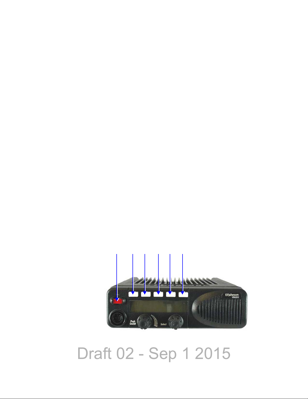
Figure 2.1 shows the controls for the Viking Mobile radio.
Figure 2.1 Front Panel Controls
Viking Mobile Radio Operating Manual 2-1
Page 28
Draft 02 - Sep 1 2015
Controls & Display
F2 F3 F4 F5 F6F1
Programmable Option Buttons
Note This indicator is disabled when the Surveillance mode is programmed (see Section 4.10)
ON-OFF /Volume - Pressing this control turns power ON and OFF (soft power down can
be programmed as in Section 3.1.1.3), and rotating it sets the volume level.
Select Switch - This switch can be pressed or rotated. An optional beep can be
programmed to sound when it is pressed. Selects zones/channels and is also used for other
functions such as selecting names from a call list. When selecting zones/channels, a bar
above the zone or channel display (see Figure 2.3) indicates which is being changed. This
bar is switched between displays by pressing this switch, and zone and channels are
selected by rotating it (see Section 3.1.7.1). If this switch is pressed and held, the radio
enters Menu Mode.
Multi-function Indicator - This is a two-color LED that indicates the following:
Red (constant) - Transmitter keyed in clear mode (PTT switch pressed).
Green (constant) - Busy condition (carrier detected in clear receive mode).
Orange (constant) - Transmitter keyed in encrypted mode (PTT switch pressed)
Red (flashing) - call received in encrypted mode
and you can program to disable when the backlight is off.
Option Buttons - Each of the six options buttons on the front panel (including the one
located to the left of the display) can be programmed by your system operator to control
some function. The button functions can be different for each operating mode
(conventional, SMARTNET/SmartZone, and Project 25 Trunking). Therefore, up to 18
functions can be controlled by these buttons. Refer to Section 4.1 for more information on
option button functions.
Figure 2.2 Option Buttons
An option button can be programmed as an Emergency button to alert a dispatcher of an
emergency condition. This button can also be programmed for other functions.
2-2 Viking Mobile Radio Operating Manual
Page 29
Draft 02 - Sep 1 2015
The user can set an external line by pressing the emergency button. External devices
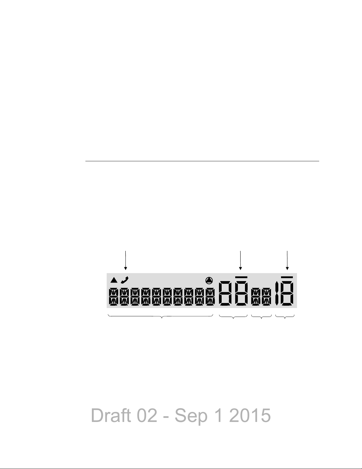
10 - Character Alphanumeric Display Zone
Number
Status
Display
Channel
Number
MON
Operating Mode
Symbols
Zone/Channel Select Indicators
can trigger off of the radio’s external line. If the “Ext Emergency” Option is enabled by
programming and the user presses the emergency button, the Aux B line on the
accessory connect shall be set to low (0V). It remains low until the External Emergency
Time has passed or the user exits the emergency. If the user presses emergency during
the External Emergency Time, the timer starts over. If the user exits emergency before
the External Emergency Time has passed, the output line returns to Vbatt.
Speaker - An internal 16-ohm, 5-watt speaker is located behind the grille. An optional 4ohm, 12-watt external speaker may be used if desired. The internal speaker should be
disabled when an external speaker is used.
2.1.2 Display
Figure 2.3 shows the front panel display.
Note Radios are capable of displaying messages in English, French or Spanish.
Controls & Display
Figure 2.3 Front Panel Display
Alphanumeric Display - This ten-character area of the display indicates the alias (unique
identification) for the selected zone, channel or combined aliases, depending on which
select mode is active. It may also indicate such things as the channel frequency, ID
numbers, and status and error messages.
Viking Mobile Radio Operating Manual 2-3
Page 30
Draft 02 - Sep 1 2015
Controls & Display
Note The zone/channel numeric display and the zone/channel select bars in all supported
Zone Number - Indicates the currently selected zone from 1 up to 255, depending on the
options installed. A zone is a collection of channels that can be any combination of the
conventional, P25 Trunked, and SMARTNET/SmartZone types.
protocols and display operating modes can be inhibited by programming.
Status Display - Two characters indicate various status information. See Table 2.1.
Channel Number - Indicates the currently selected channel (conventional) or talkgroup
(other modes). The lines above the zone and channel displays indicate which display is
changed if the Select switch is turned. To switch between displays, press the Select switch.
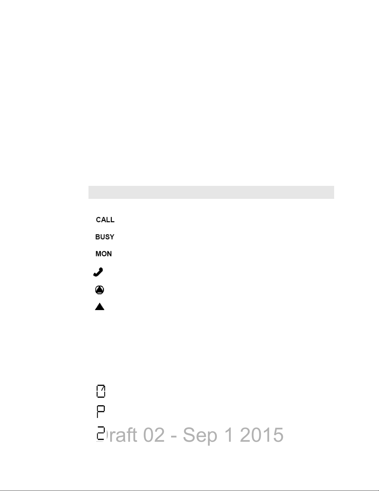
Table 2.2 lists the symbols used on the display to indicate various operating modes and
status.
Table 2.1 Standard Control Head Display Symbols
Standard Control Head Display Symbols
Operating Mode Symbols
Unit (or Private) call mode active
Busy (displayed when radio enters a busy transmit state)
Monitor mode enabled
Interconnect mode enabled
Security enabled
• Keypad programming/edit mode - displayed when the radio is in a mode where
the user can edit radio parameters.
• P25 data context enabled - radio is ready for data operations or call history
(only when radio is in conventional unit call, call alert or text messaging and an
applicable unit ID is selected.)
• P25 data channel grant (radio is operating on a data channel) or text message
mode active.
Status Display Symbols
Scan enabled
The current channel is the priority channel in the enabled scan list (only when scan is on or
when in scan edit mode; located in left position)
The current channel is the priority 2 channel in the enabled scan list (only when scan is on
or when in scan edit mode; located in left position)
2-4 Viking Mobile Radio Operating Manual
Page 31

Draft 02 - Sep 1 2015
Standard Control Head Display Symbols (Continued)
The current channel is in the enabled scan list (only when scan is on or when in scan edit
mode; located in left position)
Radio wide scan mode enabled
Selected channel is in radio wide scan list (only when radio wide scan is on or when in radio
wide scan edit mode)
Repeater talk-around enabled
2.2 Lightning Control Head
An optional component for the Viking mobile radios is the Lightning Control Head
illustrated in Figure 2.4. The Lightning Control Head offers superior readability and
display options for the radio user. The control head can be fitted to both dash and remote
mount mobile radio installations.
Controls & Display
Figure 2.4 Radio with Lightning Control Head
Viking Mobile Radio Operating Manual 2-5
Page 32

Draft 02 - Sep 1 2015
Controls & Display
On-Off / Volume
Switch
Display
Multi-Function
Indicator
Select Zone/Channel
Switch
Microphone
Connection
One-Touch
Programmable Buttons
Four-Way
Navigation Pad
2.2.1 Front Panel Controls
The Lightning Control Head front panel controls are illustrated in Figure 2.5.
Figure 2.5 Lightning Control Head Controls
On-Off Volume - This control has two actions: rotation and press. Press the control to
turn power on/off function to the radio. Rotate the control (when power is on) to adjust the
radio speaker volume.
Display - The display shows all primary operating information such as active channel,
zone, along with channel/zone alias, status symbols, and labels for the five function
buttons under the display.
Multi-function Indicator - The halo light surrounding the Select Control is used to
indicate radio transmit and receive status.
- Steady Red - Radio transmitting in clear mode
- Steady Green - Radio receiving clear
- Steady Orange - Radio idle
- Steady Yellow - Radio transmitting in encrypted mode
- Flashing Red - Radio receiving encrypted
Select Zone / Channel - This control has two actions: rotation and press. In normal nonmenu mode, press the control to select either the zone or the channel. Then rotate the
control to change either the zone or channel depending on the selection. (It is indicated on
the display whether zone or channel is selected.) Press and hold the select knob to enter
menu mode.
Microphone Connection - A compatible microphone plugs into this jack connector.
2-6 Viking Mobile Radio Operating Manual
Page 33

Draft 02 - Sep 1 2015
Controls & Display
Left Up Left Down F2 F3 F4 F5 F6 F1 Four-Way
One Touch Programming Buttons
Navigation Pad
One-Touch Buttons - The control head has 8 one-touch buttons: two on the left of the
display, five under the display, and an orange button on the right of the display. These
buttons can be programmed with different radio functions. (See the Armada Programming
manual for information on programming these button functions.)
Figure 2.6 Lightning Option Buttons
4-Way Navigation Pad - This button pad is used to navigate through various radio
functions and menus. The left and right function of the pad can be programmed with
different radio functions.
Viking Mobile Radio Operating Manual 2-7
Page 34

Draft 02 - Sep 1 2015
Controls & Display
Operating Mode Symbols / Status
Zone
Number
Channel
Name
One Touch Button Labels
Channel
Number
2.2.2 Display
The Lightning Control Head includes a highly readable display. The display is a monochrome display with 320 x 80 pixels. The display supports both the Classic Single Line
display mode (with the option to combine zone/channel on the display) or enhanced Dual
Line functionality. In Classic Single Line mode, display will have primary fields
corresponding to the fields available on the mobile Viking control head, with the addition
of the soft menu keys. Figure 2.7 shows the front panel display.
Figure 2.7 Lightning Control Head Display
Table 2.2 lists the symbols used on the display to indicate various operating modes and
status.
Table 2.2 Lightning Display Operating/Status Mode Symbols
Lightning Control Head Symbols
Keypad programming/edit mode. Displayed when the radio is in a mode where you can edit
radio settings.
Monitor mode enabled
Repeater Talk-Around mode enabled
Scan Enabled
Security Enabled
The current channel is in the enabled scan list (only when scan is on or when in scan edit
mode)
The current channel is not in the enabled scan list (only when scan is on or when in scan edit
mode)
2-8 Viking Mobile Radio Operating Manual
Page 35

Draft 02 - Sep 1 2015
Controls & Display
Lightning Control Head Symbols (Continued)
The current channel is the priority channel in the enabled scan list (only when scan is on or
when in scan edit mode)
The current channel is the priority 2 channel in the enabled scan list (only when scan is on or
when in scan edit mode)
Interconnect mode enabled
Unit call mode enabled
Radio is DRS registered
P25 data context enabled (radio is ready for data operations)
P25 data channel grant (radio is operating on a data channel)
Site lock mode
Signal strength (indicates an acceptable site, and may range from 4 bars to no bars)
GPS link active
Call history (only when radio is in conventional unit call, call alert or text messaging and an
applicable unit ID is selected.
Text message mode active
Radio wide scan mode enabled
Busy (displayed when radio enters a busy transmit state)
Transmit indication in surveillance mode, LED indicator is disabled, or “Always show Transmit/
Receive Icon” setting is enabled
Indicates that the radio is receiving a Phase 1 (FDMA) call.
Indicates that the radio is making a Phase 2 (TDMA) call.
Indicates that the radio is receiving a Phase 2 (TDMA) call.
Indicates that the radio is making a Failsoft call.
Indicates that the radio is receiving a Failsoft call.
Surveillance mode enabled
Viking Mobile Radio Operating Manual 2-9
Page 36

Draft 02 - Sep 1 2015
Controls & Display
Lightning Control Head Symbols (Continued)
Indicates that the radio is connected to a wireless access point.
2.2.3 Mobile Display Modes
If a Lightning control head is used, the zone and channel indicators can be either turned on
or off depending on the display mode programmed. If Classic Display mode is
programmed, 10 character aliases are supported. If Lightning Display mode is
programmed, 16 character aliases are supported.
2.2.3.1 Classic Mobile Display with Zone / Channel Indicators
Classic display mode on the mobile indicates that only one line of text is present. This line
of text can be up to up to 10 characters in length, and is located in the middle of the screen
vertically and in the left 2/3 of the screen horizontally. A row of icons and a row of button
labels is above and below the line of text, respectively. A combined zone/channel option is
available in this display mode.
Figure 2.8 Classic Mobile Display with Zone and Channel Indicators
2-10 Viking Mobile Radio Operating Manual
Page 37

Draft 02 - Sep 1 2015
Controls & Display
2.2.3.2 Classic Mobile Display without Zone / Channel Indicators
This mode is the same as previous, except with the zone and channel indicators removed,
the display text is located in the middle of the screen from both the horizontal and vertical
standpoints. Additionally, the display text can contain up to 10 characters. The row of
icons and button labels remains unchanged from Section 2.2.3.1. A combined zone/
channel option is available in this display mode.
Figure 2.9 Classic Mobile Display without Zone and Channel Indicators
2.2.3.3 Lightning Mobile Display with Zone / Channel Indicators
Lightning display mode indicates another row of text will be added to the Classic display
modes. The secondary row of text will be used to display the zone and/or event messages
described in section 2.2. Both lines of text are limited to 16 characters. As the indicators
are present again, both display lines will be left justified on the screen. This display mode
can display time, date, or signal strength if programmed with an optional status bar. The
icons are displayed in the middle of the status bar and the soft menu labels are displayed if
programmed.
Figure 2.10 Lightning Mobile Display with Zone and Channel Indicators
2.2.3.4 Lightning Mobile Display without Zone / Channel Indicators
This mode is the same as Section 2.2.3.3, except with the zone and channel indicators
removed, the display lines are located to the left of the screen with a dot next to the alias
indicating zone/channel selection.
Viking Mobile Radio Operating Manual 2-11
Page 38

Draft 02 - Sep 1 2015
Controls & Display
AccessoryAntenna DC Power
Additionally, the display lines can contain up to 16 characters. The icons, status bar, and
soft menu labels remain unchanged.
Figure 2.11 Lightning Mobile Display without Zone and Channel Indicators
2.3 Rear Panel Connectors
The mobile rear panel connectors are shown in Figure 2.12. These are applicable to both
the Standard and Lightning control heads.
Figure 2.12 Rear Panel Connectors
DC Power - Connection point for the nominal 12-volt, negative ground power source (see
Figure 2.12).
Antenna - Type N for connecting the antenna.
Accessory - Black connector for connecting optional accessories such as an external
speaker (4-ohm, 12-watt), horn alert, siren control, and ignition sense line.
2-12 Viking Mobile Radio Operating Manual
Page 39

Draft 02 - Sep 1 2015
2.4 Dual Control Configurations
The Viking mobile radio is available in two dual-control configurations, each with
different programming and setup requirements:
- Dash-mount radio with a remote mount control head
- Remote-mount radio with two remote control heads
Figure 2.13 Dash-Mount Radio with Remote Control Head
Controls & Display
Figure 2.14 Remote-Mount Radio with Two Remote Control Heads
Note All heads are shipped from factory set as masters. One of the heads needs to be
programmed as a slave to function correctly. Please refer to Section 2.4.4.
2.4.1 Remote Conversion Kit 250-5300-002
This kit provides the material required to convert an existing dash-mount mobile to a
remote-mount configuration. The kit includes:
- Blank faceplate for mobile unit
- Rear shroud for remote control head
- Remote control head mounting bracket
- Single remote accessory cable (part number 597-5357-706)
- 17 ft. remote control cable (part number 597-5357-775-02)
Viking Mobile Radio Operating Manual 2-13
Page 40

Draft 02 - Sep 1 2015
Controls & Display
The kit does not include the control head removal tool (part number 721-5100-010) which
must be ordered separately if required.
The remote control cable is also available in 6 foot (part number 597-5357-775-01) and 50
foot (part number 597-5357-775-03) lengths, but these must be ordered separately.
2.4.2 Remote Control Head Kit 250-5300-003
This kit includes the material required to add a remote control head to an existing dashmount or remote-mount configuration. The kit includes:
- Viking Remote control head with mounting bracket.
Due to differing operational requirements, the following items are not included in the kit
and must be ordered separately:
- Microphone - see section 3 for further details
- Remote control cable - order 6 ft., 17 ft. or 50 ft. cable as required
- Remote accessory cable - see below for part numbers
Configurations using two remote control heads require the Dual Remote / Accessory /
Data / Siren cable (part number 597-5357-741).
Configurations using a dash-mount mobile with one remote control head can use the
following remote accessory cables, depending on the application:
- Single Remote / Accessory cable (part number 597-5357-706)
- Single Remote / Accessory / UDDI cable (part number 597-5357-736)
- Single Remote / Accessory / Data / Siren cable (part number 597-5357-716)
2.4.3 Hardware Setup
When shipped, the dual remote-mount configuration consists of a dash-mount radio, a
remote control head, a conversion kit for the second control head, and required cabling.
Upon receipt, the installer must convert the dash-mount mobile radio into a remote-mount
configuration using instructions contained in the installation manual (part number 0045300-73001) which is supplied with the unit.
In the dual remote control configuration, the EFJohnson noise-cancelling microphone
(part number 589-0016-592) should be used on both control heads. This microphone can
be identified by the small circular metal grill above the hang-up button on the rear of the
microphone. Use of other microphones in this configuration will result in degraded
operational performance.
2-14 Viking Mobile Radio Operating Manual
Page 41

Draft 02 - Sep 1 2015
Controls & Display
Left Down
F2 F3 F4 F5 F6 F1
Programmable Option Buttons
Left Up
2.4.4 Master / Slave Programming
In both dual control configurations, either control head can be designated as the Master
and the other as the Slave. The Master control head controls the volume of its internal
speaker and any external speakers that are connected to the radio's eight-pin accessory
connector (see installation manual for connection details).
All Viking mobile radios ship from the factory with the dash-mount control head and any
remote control heads set as Master, so in all dual-control configurations, one control head
must be set as the Slave to ensure correct operation.
Control head addressing is set as follows:
1 Power up the mobile radio
2 Press buttons F3, F4 and F5 at the same time, and release (see Figure 2.15).
3 The display will read “ADDRESS 21” if the control head is configured as the Master,
or “ADDRESS 22” through “ADDRESS 27" if the control head is configured as the
Slave.
4 Rotate the Select knob to select the appropriate address.
5 After a short time-out period, display will read “CYCLE PWR” (Standard Control
Head) or “CYCLE POWER” (Lightning Control Head).
6 Power the radio off and back on, and the configuration will be updated.
Figure 2.15 Control Head Option Buttons
Viking Mobile Radio Operating Manual 2-15
Page 42

Draft 02 - Sep 1 2015
Controls & Display
2.4.5 Dual Control Operation
2.4.5.1 Programming Dual Remote Control Configurations
The Dual Remote configuration requires special programming to accommodate both
remote control heads in the mobile radio system.
Removal of either control head will affect system performance.
2.4.5.2 Power On / Off
The power switching in dual configurations is such that either control head can switch the
radio on, but both control heads must be off to turn the radio off.
If the power button on both control heads is pressed, then the power button on both control
heads must be pressed again to turn the radio off.
It is therefore recommended to always turn the radio on and off using one control head, to
simplify operation and avoid confusion.
2.4.5.3 Microphone Audio
In the dual remote control configuration, when transmitting from one of the control heads,
it is possible for the push-to-talk (PTT) on the microphone of the second remote head to
also be active. In this case, the voice transmissions of both users will be transmitted,
resulting in a “party line” operation. This is done to allow either control unit access to the
voice channel, and to eliminate the circumstance where one operator may be prevented
from having their transmission heard because the other control head is already
transmitting.
To prevent a second operator from interrupting a transmission already in progress, the user
should look at the transmit indicator on the control head prior to pushing PTT to verify that
the mobile radio is not already transmitting from the other control head.
2-16 Viking Mobile Radio Operating Manual
Page 43

Draft 02 - Sep 1 2015
2.5 External Speaker
An optional 4 ohm, 12 watt external speaker is available from EFJohnson (Part No. 2500151-006). This can be used to enhance radio audio or to provide primary audio for a
remote-mount radio. Refer to the Viking Mobile Radio Installation Guides for additional
installation information.
Figure 2.16 EFJohnson External Speaker
Controls & Display
2.5.1 Internal / External Speaker Programming (Standard Control Head only)
All Viking mobile radios ship from the factory with the internal speaker in the control
head enabled, and audio is also routed to the 8-pin accessory connector at the rear of the
radio.
If you connect an external speaker to the 8-pin accessory connector (as described in the
installation manual), the internal speaker will not be automatically disabled, and both
speakers will be active.
To disable the internal speaker, proceed as follows:
1 Power up the mobile radio.
2 Press buttons F2 and F5 at the same time, and release (see Figure 2.15).
3 Rotate the Select knob, until display reads “SPKR DSABL”.
4 After a short time-out period, display will read “CYCLE PWR”.
5 Power the radio off and back on, and the internal speaker will be disabled.
Viking Mobile Radio Operating Manual 2-17
Page 44

Draft 02 - Sep 1 2015
Controls & Display
To re-enable the internal speaker, proceed as follows:
1 Power up the mobile radio.
2 Press buttons F2 and F5 at the same time, and release (see Figure 2.15).
3 Rotate the Select knob, until display reads “SPKR ENABL”.
4 After a short time-out period, display will read “CYCLE PWR”.
5 Power the radio off and back on, and the internal speaker will be enabled.
2-18 Viking Mobile Radio Operating Manual
Page 45

Draft 02 - Sep 1 2015
3.1 Basic Operation
S ECTION
Section3General Operation
3.1.1 Turning Power ON and Setting Volume
Power is turned ON and OFF by pressing the ON-OFF /Volume knob. The radio goes
through a self test when power is turned ON. When that is successfully completed,
software version, unit ID, zone, then channel are briefly displayed (except when a
conventional analog channel is selected), a tone sounds (if tones are enabled), and the
radio is ready for normal operation. If “ENTER PSWD” (Standard Control Head) or
“Enter Password” (Lightning Control Head) is briefly displayed, refer to the next section.
The radio can be programmed so that one of the following combinations are selected at
power up:
- Last Zone/Last Channel
- Programmed Zone/Last Channel
- Programmed Zone/Programmed Channel
If the Radio Alias feature is enabled, the radio will display the (up-to-ten characters for the
Standard Control Head) and (up-to-sixteen characters for the Lightning Control Head)
Radio alias in place of the Self Test message during startup. Radio alias identifies the
personality file used to program the radio, the service area for which the radio is
programmed, or functional grouping for which the radio is programmed. The Radio ID
alias display will be included with the Radio Info display items in both button/scroll and
menu modes. If disabled, the Radio info menu mode will display a blank line.
Viking Mobile Radio Operating Manual 3-1
Page 46

Draft 02 - Sep 1 2015
General Operation
Note In dual control configurations, the power switch at either control point can be OFF for
power to turn OFF.
3.1.1.1 Setting Volume Level
The relative volume setting can be determined using a reference tone as follows:
• If the key press tones are enabled (see Section 4.6) and if so programmed, a short tone
sounds when an option switch is pressed or the Select switch is pressed or rotated.
• If a conventional channel is selected, take the microphone off-hook and if someone is
talking, voice may be heard. If the MON (Monitor) option switch is programmed (see
Section 5.2), pressing it unsquelches the radio and either voice or background noise is
heard. If a SMARTNET/SmartZone or P25 trunked channel is selected, the radio cannot
be manually unsquelched.
The minimum volume level that the volume control can select can be programmed. This
can be used to prevent missed messages caused by unintentionally turning the volume
down too far. Relative levels of 0-255 can be set in steps of 1 (“0” sets the lowest
minimum volume).
Note This setting is applicable to Viking mobile radios with Viking Remote Control Heads.
3.1.1.2 Unprogrammed Tones
The Viking mobile radio can be programmed so that it will not play a tone in the following
cases:
• Unprogrammed button pressed.
• Unprogrammed toggle switch activated.
• Switched to an unprogrammed channel.
3.1.1.3 Standard and Soft Power Down
To turn power off, press the ON-OFF/Volume knob.
A Soft Power Down feature can be programmed to prevent radio power from being turned
off by accidentally pressing the on-off/volume knob. The display message portion of the
display stops updating. The user is able to receive, transmit, and use function buttons, but
the display message will not change. If the channel is changed the Zone/Channel
indication will update.
The user can power the radio completely down by pressing the option button programmed
for this purpose (F2, F6, or Select button).
3-2 Viking Mobile Radio Operating Manual
Page 47

Draft 02 - Sep 1 2015
General Operation
If the user presses the ON/OFF/Volume knob while soft is in effect, the radio returns to
full power up operation.
3.1.2 Persistent Settings
Settings retained through power cycle of the Viking mobile radios include.
Global Persistent Settings
Scan
Radio Wide Scan
Secure
Tones
Tx Power
Radio Inhibit
Keypad Lockout
Conventional Persistent Settings
Selective Squelch
Repeater Talk Around
Display / Information
Disable Call Guard
P25 Trunking Persistent Settings
Dynamic Regrouping
Site Lock
SmartNet/SmartZone Persistent Settings
Dynamic Regrouping
Site Lock
3.1.3 Power-Up Password
The power-up password feature prevents unauthorized use of the radio by requiring that a
four to twelve digit password be entered to make it operational. This feature is enabled or
disabled by programming.
When it is enabled, “ENTER PSWD” (Standard Control Head) or “Enter Password”
(Lightning Control Head) is briefly displayed when power is turned on, the four to twelve
digit numeric password must be entered by pressing and rotating the Select switch. A
single beep sounds when the switch is pressed (if that option is enabled). If an incorrect
password is entered, “INCORRECT” is displayed and it must be re-entered.
Viking Mobile Radio Operating Manual 3-3
Page 48

Draft 02 - Sep 1 2015
General Operation
Note Standard Control only allows up to a ten digit password while Lightning Control Head
Note Any password changes made to the radio will be immediately applicable when Password
The current User password can be changed if the “Change User Password” function is
programmed. Selecting this function displays prompts for entering and confirming a new
password.
allows up to a twelve digit password.
3.1.3.1 Programming Passwords
Passwords are set by programming. The applicable radio must be connected to the
computer and powered up to program the password.
Management is exited.
3.1.3.2 Lost Passwords
If a password is lost, contact customer service.
3.1.3.3 Changing Passwords
An assigned user password can be changed by the user if the Change User Password
function is programmed. Selecting this function displays prompts for entering and
confirming a new password.
3.1.3.4 Password Entry Procedure
When a password is requested, rotate and press the Select switch. A single beep sounds
when the switch is pressed (if that option is selected)
3.1.3.5 Zone Password
A zone password can be programmed with the Viking mobile radio. It prevents
unauthorized reprogramming of zones by keypad programming.
Note The programming and usage of this password has not changed. It is independent from the
preceding passwords, and is set by programming.
3-4 Viking Mobile Radio Operating Manual
Page 49

Draft 02 - Sep 1 2015
General Operation
3.1.4 Speaking into the Microphone
For best results, hold the microphone about 1-2 inches from your mouth and speak at a
normal conversational level. Do not shout since it distorts your voice and does not
increase range.
Note If excessive background noise consistently interferes with communications, Microphone
Levels can be adjusted by programming.
Make sure that the PTT (push-to-talk) switch is pressed before you begin to speak and
released as soon as the message is complete.
3.1.5 Display Backlight Control
If the Backlight function is programmed, it can be used to select Bright, Dim, or Off
backlight modes. Otherwise, the keypad and display backlight is fixed in one of these
modes by programming. The backlight is totally disabled when the Surveillance mode is
programmed (see Section 4.10).
3.1.6 Display V iewing Angle & Contrast Adjust (Standard Control Head Only)
If the display on the standard head is difficult to read from the angle you normally view it,
the viewing angle can be adjusted as follows: Press and hold F2 and F6 to enter angle
change mode. If you do not rotate the select switch for three seconds, it times out and goes
back to zone or channel change.
Note If the display appears blank or all icons are continuously displayed, the viewing angle is
probably improperly adjusted.
Viking Mobile Radio Operating Manual 3-5
Page 50

Draft 02 - Sep 1 2015
General Operation
Zone
Number
Channel
Number
Zone Select Indicator
Zone Identifier Alias
3.1.7 Zone / Channel Display and Select
The selected zone is shown on the radio display (Figure 3.1). When selected by the Zone/
Channel switch (see Section 3.1.7.1), the select bar will display above the Zone Number.
In addition, the alias text identifier for the selected zone will be shown on the display
screen.
Figure 3.1 Zone Display
Similar to the selected zone, the selected channel is shown on the radio display (Figure
3.2). When selected by the Zone/Channel switch (see Section 3.1.7.1), the select bar will
display above the Channel Number. In addition, the alias text identifier for the selected
channel will be shown on the display screen.
3-6 Viking Mobile Radio Operating Manual
Page 51

Draft 02 - Sep 1 2015
General Operation
Zone
Number
Channel
Number
Channel Select Indicator
Channel Identifier Alias
Channel alias can be a combination of zone and channel aliases. With conventional
channels, the channel frequency may be displayed instead of the alias if the Display
Information function is programmed (see Section 5.8).
Figure 3.2 Channel Display
If channel scanning is enabled, the channel number will change to show the current active
channel being scanned. The Channel Identifier Alias will also change to identify the
current active scanned channel.
3.1.7.1 Zone / Channel Select
The front panel Select switch is used to change the zone and channel. Pressing this switch
toggles between the zone and channel select modes, and rotating it changes the zone or
channel. An optional beep can be programmed to sound when the switch is pressed or the
channel is changed.
The current mode is indicated by the bar over the zone or channel display. For example,
when the bar is over the zone display, the zone select mode is enabled.
Rotating the Select switch clockwise increases the zone or channel and rotating it
counterclockwise decreases the zone or channel number. A single beep sounds when the
channel is changed (if that option is enabled). After the highest zone or channel is
displayed, wrap-around to the lowest zone or channel occurs and vice versa. If an
unprogrammed channel is selected, “UNPROGRAMD” is displayed and a tone sounds.
The radio may also be programmed so that only programmed channels are selected.
The radio can be programmed so that the bar defaults to either the zone or channel display
when power is turned ON and after a change is made. The delay that occurs before it
returns is programmed for 0-99 seconds. It can also be programmed to remain in the last
selected mode.
Viking Mobile Radio Operating Manual 3-7
Page 52

Draft 02 - Sep 1 2015
General Operation
Seq. Ch. No. Zone Channel
111
255 255
256 2 256
510 510
511 3 511
765 765
.
.
2048
.
.
.
.
.
2048*
3.1.7.2 Direct Channel Select
The direct Channel Select feature is available if the Channel Select option switch or menu
parameter is programmed. This feature allows channels to be directly selected using the
Digital Keypad Microphone. Please note that a Digital Keypad Mic is required for Direct
entry.
For direct selection purposes, channels are numbered sequentially starting with the lowest
zone. Each zone can be programmed with up to 255 channels with up to 2048 channels
total.
Proceed as follows to select channels using this mode:
1 Enable the direct Channel Select mode selecting it via the menu or by pressing the
Channel Select option switch. A single beep sounds when the switch is pressed (if that
3-8 Viking Mobile Radio Operating Manual
option is enabled). The alias and sequential number of the current channel are
alternately displayed.
2 Select the desired channel using the channel select knob or directly enter it using the 0-
9 keys. A single beep sounds when the channel is changed (if that option is enabled). If
using the 0-9 keys, the radio attempts to display the entered number after the third digit
is entered or approximately two seconds after the last key is pressed.
3 To exit this mode and select the entered channel, press the Channel Select switch again.
This mode is also exited automatically without changing the channel after
approximately one minute of no activity.
Other features of this mode are as follows:
Page 53

Draft 02 - Sep 1 2015
General Operation
• When using the Channel Select knob, wrap-around to the lowest zone/channel occurs
after the last channel in the highest programmed zone is displayed and vice versa. For
example, if Zone 1/Channel 5 is the highest programmed channel, wrap-around occurs
after Zone 1/Channel 16 is displayed if the “Programmed Channels Only On Display” is
not selected. If “Programmed Channels Only on Display” is selected, the wrap around
occurs at Channel 5.
• When an unprogrammed channel is displayed, the sequential channel number and
“UNPROGRAMD” are alternately displayed.
• If an invalid channel number is entered using the 0-9 keys, or the Channel Select option
switch is pressed with “UNPROGRAMD” displayed, an error tone sounds,
“INVALID” is briefly displayed, and the displayed channel does not change.
3.1.8 Setting Squelch Control
The user can program a menu item, soft button item (Lightning Control Head only), or
function button, for squelch adjust. While on a conventional analog channel without
emergency or scan active, the user can select the programmed button or menu item for
squelch adjust. The current squelch setting will show on the display. Using the up and
down navigation buttons, or turning the rotary knob clockwise or counter-clockwise on
the mobile radio, the user can adjust the squelch setting to a desired level from -7 to +7.
Increasing the value towards +7 causes the squelch to open sooner for weaker signals
while decreasing towards -7 has the opposite effects. Pressing the select button will store
the new squelch setting and return the user to the main display.
The squelch level is preset and may not require readjustment. However, if the squelch
threshold needs to be changed on a conventional analog channel, it can be changed in the
same way as though using keypad programming if available (see Section 5.14).
Note The Keypad programming feature is available to Federal Government users only.
3.1.9 Zone Edit
Users can build a virtual zone consisting of channels already present in the radio. They can
add or remove channels from zones while the radio is running, allowing changes to be
made at runtime.
The Zone Edit feature can be programmed. It can be toggled on or off on a per-zone basis.
When enabled, it allows you to copy and delete existing channels from a zone.
Only channels within Zone Edit enabled zones can be selected for editing.
• Zone Edit mode can be entered via button press or the menu.
• A momentary button press performs channel copy.
Viking Mobile Radio Operating Manual 3-9
Page 54

Draft 02 - Sep 1 2015
General Operation
• A press-and-hold performs channel delete.
To copy a channel:
1 Navigate to the channel and select “channel copy”.
2 Select the destination, first the zone and then the channel.
3 These can be selected by the navigation pad or using direct entry.
4 If the destination channel exists, it is overwritten without warning.
When deleting a channel, first select a zone and then the channel to delete.
There are a number of restrictions in place to prevent you from causing problems with the
existing radio configuration. If you want to copy or delete a channel that is blocked by one
of these restrictions, the radio programming software can be used to make the change.
(Please contact your system administrator.)
Copy
Condition
The destination channel is the current
channel
The selected zone is full (255 Channels) No Yes
The radio has no free channels No Yes
The channel is a fire mode channel No No
The channel is a scan list channel No No
The channel is a RWS list channel No No
The channel is a global emergency
channel
Allowed?
No No
No No
Delete
Allowed?
3.1.10 Transmit Disable
Transmitting can be disabled on each conventional, SMARTNET, SmartZone, and P25
Trunking channel so that the channel is monitor-only. When transmitting is attempted on a
receive-only channel, “RX ONLY” (Standard Control Head) or “Receive Only”
(Lightning Control Head) is displayed and an error tone sounds.
3-10 Viking Mobile Radio Operating Manual
Page 55

Draft 02 - Sep 1 2015
General Operation
CAUTION
!
3.1.11 Operation At Extended Range
When approaching the limits of radio range, the other party may not be able to hear your
transmissions and there may be an increase in background noise when messages are
received. You may still be out of range even though you can hear a message. The reason
for this is that the signal you are receiving is usually transmitted at a higher power level
than the one transmitted by your radio. Communication may be improved by moving to
higher ground or away from shielding objects such as tall buildings or hills.
The radio can be programmed to provide an out-of-range indicator when used on an
EFJohnson Infrastructure system. For more information, please see Section 5.13.4.
3.1.12 Preventing Vehicle Battery Discharge
In the standby mode (power on, not transmitting), radio power consumption is relatively
low. Therefore, you can probably leave the radio ON for one or two days without
operating the vehicle and the battery should not become seriously discharged. However, if
the outdoor temperature is low enough to significantly decrease battery capacity, the radio
should be turned OFF when not in use. Also if display is on “high” and you are receiving
calls, the battery charge can drain in less than a day.
Since power consumption is significantly higher when transmitting, it is good practice to
have the vehicle running while transmitting. This ensures that optimum power is being
delivered to the radio and that the battery does not become discharged.
3.1.13 Cleaning the Control Head
The radio Control Head requires periodic cleaning, depending upon the operating
environment.
You will need a soft brush of a size that can access all exposed areas of the Control Head.
You will also need a vacuum cleaner that is portable enough to easily access the Control
Head.
To clean the Control Head:
1 Use the brush to remove the bulk of sand and dust from the Control Head.
Ensure that this is done in an environment that does not allow other equipment to be
affected by the removed sand and dust. If necessary, use the vacuum to collect material as
it is removed.
Viking Mobile Radio Operating Manual 3-11
Page 56

Draft 02 - Sep 1 2015
General Operation
2 When the bulk of sand and dust is removed, use the brush to clean the interface joint
between the buttons and Control Head plastic.
3 Position the vacuum nozzle two inches (or more, as required) from the face of the
Control Head. Use the brush to remove any remaining sand and dust.
4 Repeat this procedure until the Control Head is completely clean.
3.1.14 Radio Service
If “UNPROGRAMD” is displayed, the cause can be any of the following:
• An unprogrammed channel is selected. Select a programmed channel.
• The selected channel is programmed for an option that is not installed or an error in
programming was detected. Contact your system operator for service.
If the channel is programmed for a system type not programmed, “DISABLED” is
displayed.
If no characters or all characters appear in the display, the viewing angle may be
improperly adjusted. If some other problem is occurring, turn power OFF and then ON
again to reset the control logic. Also make sure that the controls are properly set and that
the power, external speaker, and accessory cables (if used) are securely plugged into the
back of the radio.
If the radio is completely inoperative, check the Main power and ignition sense line fuse.
If it is blown, remedy the cause if possible and replace it with the same type (1A, 15A). If
the radio still does not operate properly, return it to your system operator for service.
Note There are no user-serviceable components in the radio. Altering internal adjustments can
cause illegal emissions, void the warranty, and result in improper operation that can
seriously damage the radio.
Note If the vehicle itself needs to be jump started, the mobile fuses must be pulled before jump
starting to prevent damage to the radio!
3.2 Single Touch
The Single Touch feature allows a Viking radio user to send a predefined Status, Message,
Call Alert, Unit Call, or Interconnect Call by pressing and holding a button. For each
system, up to four buttons in Armada can be programmed for Single Touch. The Single
Touch feature allows a user to bypass the menu and PTT to send a Status, Message, Call
Alert, Unit Call, or Interconnect Call. A maximum of four buttons are programmable to
3-12 Viking Mobile Radio Operating Manual
Page 57

Draft 02 - Sep 1 2015
General Operation
the radio per system and zone. The Single Touch buttons are press and hold buttons
preventing a user from sending statuses, messages, and calls by accident. On a Single
Touch button press, the radio displays two dual temp messages; the first displays which
Single Touch button was pressed along with the press and hold message. The second
displays the Alias and the ID/Phone Number (If applicable – for Status and Message only
the Alias is displayed since neither has an ID).
3.2.1 Single Touch Buttons
1 The Single Touch buttons are activated on a press and hold which will be in the range
of 0.5 to 2.5 seconds. This is set in Armada.
2 Both physical and soft buttons may be used for Single Touch, but it is not available as a
menu item.
3 If a Single Touch button is pressed, or pressed and held, but the Feature combo box is
set to Disabled, then “Disabled” is displayed along with a short bad beep tone.
4 The supported Single Touch functions for each system are shown below.
Function
Disabled
Unit Call
Call Alert
Status
Message
Interconnect Call
3.2.2 Detailed Single Touch Operation
The following describes how each supported Single Touch function operates, and how it
varies slightly from system to system. As a note, only Digital conventional channels
support Single Touch. If a Single Touch button is used on an Analog Conventional
channel, the temporary message “Analog” is displayed.
Supported Functions
P25
Trunking
Smartnet /
Smartzone
Specific Entry TypeConventional
Call List
Call List
Status List
Message Aliases List
Phone List
3.2.2.1 Conventional Unit Call
This is the only function that requires the user to press the PTT to send the call.
Viking Mobile Radio Operating Manual 3-13
Page 58

Draft 02 - Sep 1 2015
General Operation
To Send a Single Touch Unit Call
1 Press and Hold the Single Touch button assigned to Unit Call.
2 The Unit ID to call is displayed on the top line with the Alias displayed on the bottom
line.
3 To send the call, press the PTT button.
4 The operation will now continue the same as Unit Call.
5 To exit the call, either press the Clear button or the Single Touch button pressed for
entry.
To Answer a Unit Call Using Single Touch
1 When the radio is receiving an incoming call, press and hold the Single Touch button
assigned to Unit Call.
2 The PTT button must then be pressed to answer.
3 Once the PTT button has been pressed the operation continues the same as the normal
Unit Call.
4 To exit the call, either press the Clear button or the Single Touch button assigned to
Unit Call.
3.2.2.2 Conventional Call Alert
1 To use Call Alert, the Call Alert Encode option must be checked in Armada under Sys-
tems (Conventional) → General Options → P25 Conv System Options.
2 Without this checked a bad tone will sound on a press and hold.
3 To send a Call Alert, press and hold the Single Touch button assigned to Call Alert.
4 While sending the Call Alert, the Unit ID of the radio the alert is being sent to is
displayed on top along with the alias on the bottom line.
5 Once a Call Alert has been sent operation continues the same as the normal Call Alert.
6 To exit the call alert, either press the Clear button or the Single Touch button assigned
to Call Alert.
3.2.2.3 Conventional Status
1 To send a Status, press and hold the Single Touch button assigned to Status.
3-14 Viking Mobile Radio Operating Manual
Page 59

Draft 02 - Sep 1 2015
General Operation
2 While sending a Status, the alias of the Status being sent is displayed.
3 Once the Status has been sent operation continues the same as the normal Status with
the exception being that only the PTT may be used to resend the Status while the
transmission is still active.
4 Once the status transmission is successful or fails, a success or failure message is
displayed.
5 After a success or failure, the radio will exit the status mode.
6 To exit before the Status finishes, either press the Clear button or the Single Touch
button assigned to Status.
3.2.2.4 Conventional Message
This is the same operation as Conventional Status except that a Message is being sent.
1 To send a Status, press and hold the Single Touch button assigned to Message.
2 While sending a Status, the alias of the Message being sent is displayed.
3 Once the Message has been sent operation continues the same as the normal Message
with the exception being that only the PTT may be used to resend the Message while
the transmission is still active.
4 Once the Message transmission is successful or fails, a success or failure message is
displayed.
5 After a success or failure, the radio will exit the Message mode.
6 To exit before the Message finishes, either press the Clear button or the Single Touch
button assigned to Message.
3.2.2.5 P25 Unit Call
In Armada the Unit Call can be set to Standard or Enhanced. Single Touch supports both
and they each operate the same as a normal Standard or Enhanced Unit Call. To answer a
unit call the PTT needs to be pressed after the Single Touch button is pressed and held.
To Send a Single Touch Unit Call
1 To send a Unit Call, press and hold the Single Touch button assigned to Unit Call.
2 For the radio to send, the Unit Call Usage in Armada under Systems(P25) → Lists →
Call Settings must be set to Unlimited or List Only.
Viking Mobile Radio Operating Manual 3-15
Page 60

Draft 02 - Sep 1 2015
General Operation
3 If it is set to Disabled or Response Only; when the Single Touch button is pressed and
held the radio will display “Disabled”, “RSPNS ONLY” (Standard Control Head), or
“Response Only” (Lightning Control Head)
4 Once the Unit Call has been sent, operation continues as normal for Unit Call.
5 The alias of the radio being called followed by “wait” will be displayed.
6 If the radio called does not answer, a time-out message is displayed. When this is
displayed any key on the radio exits the Unit Call.
7 To exit the call either press the Clear button or the Single Touch button assigned to Unit
Call.
To Answer a Unit Call Using Single Touch
1 When receiving a Unit Call, press and hold the Single Touch button assigned to Unit
Call.
2 Then press the PTT button to answer the Unit Call.
3 For the radio to receive, the Unit Call Usage in Armada under Systems(P25) → Lists →
Call Settings must be set to Response Only, List Only, or Unlimited.
4 Once the received Unit Call is active, operation continues as normal for Unit Call.
5 The alias of the calling radio will be displayed.
6 To exit the call either press the Clear button or the Single Touch button assigned to Unit
Call.
3.2.2.6 P25 Call Alert
1 To send a Call Alert, press and hold the Single Touch button assigned to Call Alert.
2 For the radio to send the Call Alert, the Call Alert Usage in Armada under
Systems(P25) → Lists → Call Settings must be set to List Only or Unlimited.
3 Once the alert is sent, operation continues as normal for Call Alert.
4 After finishing either an Ack Received message or a No Ack message is displayed and
Call Alert is exited.
5 To exit before those messages either press the Clear button or the Single Touch button
assigned to Call Alert.
3-16 Viking Mobile Radio Operating Manual
Page 61

Draft 02 - Sep 1 2015
General Operation
3.2.2.7 P25 Status
1 To send a Status, press and hold the Single Touch button assigned to Status.
2 The Status alias programmed to Single Touch is displayed for one second.
3 Either an Ack Received message or a Status Fail message is displayed after the Status
has been sent.
4 Once the Status is sent, operation continues as normally would in a Status. For example
the same buttons are available for use as they would be by sending a Status through the
menu.
5 The Status is not able to be exited while sending unless it is canceled by another
function. The user must wait for the Ack or the Fail message.
3.2.2.8 P25 Interconnect
1 To start an Interconnect Call, press and hold the Single Touch button assigned to Inter-
connect.
2 The alias of the phone number being called will be displayed.
3 Once the call is started through Single Touch, operation continues as normal for
Interconnect Call.
4 To exit the call either press the Clear button or the Single Touch button assigned to
Interconnect.
5 To answer an Interconnect Call with the Single Touch button press and hold it.
6 Once pressed and held the incoming call will be answered and operation will continue
as would on a normal Interconnect Call answer.
3.2.2.9 SNSZ Unit Call
In Armada the Unit Call can be set to Standard or Enhanced. Single Touch supports both
and they each operate the same as a normal Standard or Enhanced Unit Call. To answer a
unit call the PTT needs to be pressed after the Single Touch button is pressed and held.
To Send a Single Touch Unit Call
1 To send a Unit Call press and hold the Single Touch button assigned to Unit Call.
2 For the radio to send, the Unit Call Usage in Armada under Systems (Smartnet/
Smartzone) → Lists → Call Settings must be set to Unlimited or List Only.
Viking Mobile Radio Operating Manual 3-17
Page 62

Draft 02 - Sep 1 2015
General Operation
3 If it is set to Disabled or Response Only; when the Single Touch button is pressed and
held the radio will display “Disabled”, “RSPNS ONLY” (Standard Control Head), or
“Response Only” (Lightning Control Head).
4 The alias of the radio being called will be displayed.
5 The operation will now continue the same as a normal Unit Call.
6 If the radio called does not answer, a no ack message is displayed. When this is
displayed any key on the radio exits the Unit Call.
7 To exit the call either press the Clear button or the Single Touch button assigned to Unit
Call.
To Answer a Unit Call Using Single Touch
1 When receiving a Unit Call, press and hold the Single Touch button assigned to Unit
Call.
2 Then press the PTT button to answer the Unit Call.
3 For the radio to receive, the Unit Call Usage in Armada under Systems (Smartnet/
Smartzone) → Lists → Call Settings must be set to Response Only, List Only, or
Unlimited.
4 Once the received Unit Call is active, operation continues as normal for Unit Call.
5 The alias of the calling radio will be displayed.
6 To exit the call either press the Clear button or the Single Touch button assigned to Unit
Call.
3.2.2.10 SNSZ Call Alert
1 To send a Call Alert, press and hold the Single Touch button assigned to Call Alert.
2 For the radio to send the Call Alert, the Unit Call Usage in Armada under Systems
(Smartnet/Smartzone) → Lists → Call Settings must be set to List Only or Unlimited.
3 The Unit ID the radio is sending to is shortly displayed followed by the wait message
until an Ack or No Ack message is displayed.
4 Once the alert is sent, operation continues as normal for Call Alert and all buttons that
are available in Call Alert are available in Single Touch Call Alert.
5 To exit before those messages either press the Clear button or the Single Touch button
assigned to Call Alert.
3-18 Viking Mobile Radio Operating Manual
Page 63

Draft 02 - Sep 1 2015
General Operation
3.2.2.11 SNSZ Status
1 To send a Status, press and hold the Single Touch button assigned to Status.
2 The Status alias programmed to Single Touch is displayed for one second.
3 Either an Ack Received message or a Status Fail message is displayed after the Status
has been sent.
4 Once the Status is sent, operation continues as normal for Status.
5 The Status is not able to be exited while sending unless it is canceled by another
function. The user must wait for the Ack or the Fail message.
3.2.2.12 SNSZ Message:
This is same operation as Smartnet/Smartzone Status except that a Message is being sent.
1 To send a Message, press and hold the Single Touch button assigned to Message.
2 The Message alias programmed to Single Touch is displayed for one second.
3 Either an Ack Received message or a Message Fail message is displayed after the
Message has been sent.
4 Once the Status is sent, operation continues as normal for Message.
5 The Message is not able to be exited while sending unless it is canceled by another
function. The user must wait for the Ack or the Fail message.
3.2.2.13 SNSZ Interconnect:
1 To start an Interconnect Call, press and hold the Single Touch button assigned to Inter-
connect.
2 The alias of the phone number being called will be displayed.
3 Once the call is started through Single Touch, operation continues as normal for
Interconnect Call.
4 To exit the call either press the Clear button or the Single Touch button assigned to
Interconnect.
5 To answer an Interconnect Call with the Single Touch button press and hold it.
6 Once pressed and held the incoming call will be answered and operation will continue
as normal for Interconnect Call.
Viking Mobile Radio Operating Manual 3-19
Page 64

Draft 02 - Sep 1 2015
General Operation
3.3 Radio Inhibit
The radio can receive inhibit commands over the air or through the side port. When the
radio receives an inhibit command the screen goes blank, audio stops, lights turn off, and
most of the controls are disabled. The radio is (from the user’s perspective) frozen. Behind
the scenes, however, the radio is still running. It is waiting for an uninhibit command. If it
receives an uninhibit command, the radio User Interface is enabled and the radio will
operate normally. The general idea behind the feature is fairly simple but there are
exceptions.
• Smartport cannot be used to uninhibit a radio. (Unless an “Allow Uninhibit with RSD”
security policy is on the radio)
• If the radio is rebooted while inhibited, the radio is forced to power up on the channel it
was inhibited on.
• When powering up while inhibited, the backlight and LED will not come on.
• When powering down while inhibited, the display will not display “Powering Down”.
• In conventional mode, the radio waits until the inhibit/uninhibit acknowledgement is
sent before becoming inhibited/uninhibited. This is important mainly for uninhibit
where a race condition existed between the ack being sent and rebooting. If the radio
cannot send the ack, the system will need to retry the inhibit/uninhibit command.
3.4 Setting Squelch
The user can program a menu item, soft button (Lightning Control Head only), or function
button, for squelch adjust. While on a conventional analog channel without emergency or
scan active, the user can select the programmed button or menu item for squelch adjust.
The current squelch setting will show on the display. Using the up and down button on the
Navigation Pad (Lightning Control Head Only) or rotating the select knob on the mobile
radio, the user can adjust the squelch setting to a desired level from -7 to +7. Increasing the
value towards +7 causes the squelch to open sooner for weaker signals while decreasing
towards -7 has the opposite effects. Pressing the select button will store the new squelch
setting and return the user to the main display.
The squelch level is preset and may not require readjustment. However, if the squelch
threshold needs to be changed on a conventional analog channel, it can be changed in the
same way as though using keypad programming if available. The squelch level is preset
during alignment. If the keypad programming feature is available (see Section 5.14), the
squelch threshold can be changed by the user on each conventional analog channel.
Note The Keypad Programming feature is available to Federal Government users only.
3-20 Viking Mobile Radio Operating Manual
Page 65

Draft 02 - Sep 1 2015
3.5 Operating Modes
Each selectable channel can be programmed for the conventional (analog or Project 25
digital), SMARTNET/SmartZone, or Project 25 digital trunking operating mode. For
example, Zone 1/Channel 1 could be a conventional channel, Zone 1/Channel 2 a
SMARTNET channel, and so on. More information on these modes follows.
Note All operating modes utilize certain functions that are activated/deactivated by pressing
and holding a particular button or switch. The “hold” interval is preset. When instructed
to “press and hold”, do so until the desired action occurs or a tone sounds indicating the
option is activated. For other operations (not specified “press and hold”) on ly momentary
pressing is required.
3.5.1 Conventional Mode
This is a non-trunked operating mode which accesses independent radio channels. There is
no automatic access to several channels. Selecting a conventional channel selects a
transmit and receive frequency and other channel parameters such as squelch control
coding.
General Operation
Conventional channels can be either standard (analog), Project 25 (digital), or mix mode.
With digital operation, the DSP (Digital Signal Processor) converts the audio signal to
digital data packets. Another difference is that analog channels use Call Guard (CTCSS/
DCS) squelch control and Project 25 channels use a NAC (Network Access Code) and
talkgroup ID codes.
With Project 25 operation, a NAC is transmitted which must match the NAC programmed
in the repeater or base station equipment and the radio(s) being called for communication
to occur. In addition, to receive standard group calls, the receiving radio must be
programmed to detect the transmitted talkgroup ID code.
With conventional operation, a busy channel condition is detected automatically if the
busy channel lockout (transmit disable on busy) feature is programmed. Otherwise, it must
be detected manually. If the Out of Range indicators are not programmed, an out-of-range
condition is not indicated by special tones or messages as with trunking operation because
there is no initial data exchange with the repeater that allows this condition to be detected.
(For more information about Out of Range indicators, please see Section 3.1.11.)
Operating features unique to conventional channels are described in Section 5.
Viking Mobile Radio Operating Manual 3-21
Page 66

Draft 02 - Sep 1 2015
General Operation
3.5.2 SMARTNET / SmartZone Mode
This is a trunked operating mode in which automatic access is provided to several RF
channels. ID codes are used to select what radios are being called and what calls are
received. Monitoring is performed automatically and special messages and tones indicate
busy and out-of-range conditions.
SMARTNET and SmartZone operation and programming is very similar. Basically,
SMARTNET operation is limited to a single repeater site and SmartZone operation allows
automatic roaming between sites. SMARTNET/SmartZone features include roaming
(SmartZone only), telephone, unit, emergency calls, Call Alert
analog or digital signaling may be used. Enhanced SMARTNET/SmartZone features
provide the same, plus gives you responses from the system. For example, if the ID you
are calling is turned OFF, the system will display “NOT AVAILABLE”.
When a SMARTNET or SmartZone channel is selected or the radio is powered up on one
of those channels, it searches for a control channel. While searching, the alias (name) of
the selected channel is displayed and the radio attempts to register on the trunked system.
If a control channel could not be found (because of an out of range condition or the system
ID is not correct, for example), “NO SYS” (early units) or “OUT OF RNG” (later units) is
displayed and the radio continues to search for a control channel.
™
, and messaging. Either
The control channel transmits and receives system information to and from all radios
registered on the system. Therefore, once a control channel is found, it is continuously
monitored for incoming call information and is used to make call requests. When the radio
is keyed, a channel grant request is sent through the control channel. The system then
informs the requesting radio what traffic channel to use, through the control channel. Once
the request is granted by the system, the radio moves to the designated traffic channel for
the actual talkgroup call. Once the transmission has ended, the radio returns to the control
channel.
Operating features unique to SMARTNET/SmartZone channels are described in Section 6.
3.5.3 P25 Trunking Mode
The P25 Trunking operating features are very similar to the SmartZone type just
described. Since SmartZone features are also similar to SMARTNET features, all three
modes are described in Section 6. Some differences between the P25 Trunking and
SmartZone modes are as follows:
• Digital signaling is always used with P25 calls. Either analog or digital signaling may be
used for SmartZone calls.
• Calls made to a specific radio in the P25 mode are called Unit Calls. In the
SMARTNET/SmartZone mode they are also called Unit Calls.
• Telephone calls are available in this mode.
3-22 Viking Mobile Radio Operating Manual
Page 67

Draft 02 - Sep 1 2015
General Operation
• The P25 control channel data rate is 9600 baud and the digital voice data rate is also
9600 baud. With SmartZone operation, the control channel data rate is 3600 baud (both
digital and analog calls) and the narrowband digital voice data rate is 9600 baud.
• The P25 mode uses a system ID, Wide Area Communications Network (WACN) ID,
and RF Subsystem ID (RFSS). The SmartZone mode does not use the WACN and
RFSS IDs.
• P25 Unit IDs can be 1-16,777,211 (000001-FFFFFB hex) and SmartZone Unit IDs can
be 1-65,534 (0001-FFFE hex).
3.5.4 Systems, Channels, and Zones
A zone and channel are selected to place and receive calls. The following describes the
relationship between systems, channels, and zones.
3.5.4.1 Systems
A system is a collection of channels or talkgroups belonging to the same repeater site. It
defines all the parameters and protocol information required to access a site. Up to 255
systems of any type can be programmed depending on the option enabled.
The maximum number of channels assignable to a system is limited to 2048. Channels
may also be limited by radio limitations, programmed options, and/or available memory
space as described in the following information.
3.5.4.2 Channels
A channel selects a radio (RF) channel or talkgroup as follows:
Conventional Analog Mode - A channel selects a specific radio channel, Call Guard
(CTCSS/DCS) squelch coding, and other parameters unique to that channel.
Conventional Project 25 Mode - A channel selects a specific radio channel, NAC
squelch coding, talkgroup ID, and other parameters unique to that channel.
SMARTNET/SmartZone and Trunked Project 25 Modes - A channel selects a
specific talkgroup/announcement group, emergency group, and other parameters
unique to that talkgroup.
A maximum of up to 2048 channels can be programmed with the preceding modes
depending on the option enabled. These channels can belong to a single system or multiple
systems.
Viking Mobile Radio Operating Manual 3-23
Page 68

Draft 02 - Sep 1 2015
General Operation
3.5.4.3 Zones
A zone is a collection of up to 255 channels of any type. For example, a zone could include
12 conventional channels and four P25 Trunking channels. One use of zones may be to
program the channels used for operation in different geographical areas. The maximum
number of zones is 255.
3-24 Viking Mobile Radio Operating Manual
Page 69

Draft 02 - Sep 1 2015
Radio wide features are features common to all operating modes.
Left Up Left Down F2 F3 F4 F5 F6 F1 4-Way
Navigation Pad
4.1 Option Buttons
S ECTION
Section4Radio Wide Features
Six option buttons on the front panel (one is located to the left of the display) can be
programmed to control a different set of functions for each of the three operating modes.
Therefore, up to 24 different functions can be controlled by these buttons (six each for
Conventional, SMARTNET/SmartZone, and P25 Trunking).
Figure 4.1 Option Buttons
Viking Mobile Radio Operating Manual 4-1
Page 70

Draft 02 - Sep 1 2015
Radio Wide Features
The available functions in each mode are shown in Table 4.1
Table 4.1 Programmable Option Button, Soft Button, and Menu Mode Functions
X = Available in Mode: Menu
Display
(Standard
Function
Conventional
Project 25
Trunking SMARTNET SmartZone
Control
Head)
Menu
Display
(Lightning
Control
Head)
Soft Button
Display
(Lightning
Control
Head)
Alert tones X X X X TONES
Analog Noise
Reduction
Authentication
Keyload
Auto Site Search X X X AUTO SITE
Backlight Bright/
Dim/Off
Call Alert (Pag-
ing)
Call Response X X X CALL RESP.
Cancel Dynamic
Regroup
Change Keyset X X X X
Change User
Password
Channel
Announcement
Channel Select X X X X
Clear/Secure
Encryption Select
Clock X X X XCLOCK
Disable Call
Guard
Display GPS X X X X
Display Informa-
tion
Emergency Mode X X X X
Emergency Clear X X X X EMERG CLR
Erase Keys X X X X
Function Recall X X X X
GPS X X X X GPS
High/Low Power X X X X TX POWER
Home X X X XHOME
X X X ANALOG NR
X AUTH KEY
X X X X BACKLIGHT
X X X X CALL ALERT
XXXCANCEL DR
CHG KEY-
SET
X X X X PASSWORD
XXXX
X X X X SECURITY
X DISABLE CG
X DISPLAY
CHAN
ANNCMNT
CHAN
SELCT
DISPLAY
GPS
EMER-
GENCY
ERASE
KEYS
FUNC
RCALL
Tones TONE
Analog
Noise Rd
Auth Keyload AUTH
Auto Site SITE
Backlight BKLHT
Call Alert ALERT
Call Response RESP
Cancel Dyn
Change Key-
Password PSWD
Announce
Channel
Select
Security SECR
Disable CG DISCG
Display GPS GPSDP
Display DISP
Emergency EMER
Emergency
Erase Keys KYCLR
Function
Recall
Tx Power TXPWR
Home HOME
Shaded Features support the secondary press and hold function.
ANR
Rgrp
set
Chan
Clock CLOCK
Clear
GPS GPS
CANDR
KYSET
ANNCH
CHAN
EMCLR
FRCAL
4-2 Viking Mobile Radio Operating Manual
Page 71

Draft 02 - Sep 1 2015
Table 4.1 Programmable Option Button, Soft Button, and Menu Mode Functions
X = Available in Mode: Menu
Display
(Standard
Function
Conventional
Project 25
Trunking SMARTNETSmartZone
Control
Head)
Radio Wide Features
Menu
Display
(Lightning
Control
Head)
Soft Button
Display
(Lightning
Control
Head)
Home 2 X X X XHOME 2
Horn Honk X X X X HORN HONK
Key Select X X X KEY SELECT
Keypad Program-
ming
Message X X X X MESSAGE
Mic To PA X X X X MIC TO PA
Monitor Mode X MONITOR
Mute/Unmute X X X X
Normal/Selective
Squelch
OORI Tone X OORI TONE
P25 Packet Data X X P25 DATA
Phone Call X X X X PHONE
Priority Channel
Select
RWS List Edit X X X X RWS EDIT
RWS List Select X X X X RWS SELCT
Radio Info X X X X RADIO INFO
Radio Wide Scan X X X X RW SCAN
Rekey Request X X
Remote Access X X X X
Repeater Talk
Around
Request to Talk XRTT
RX to PA X X X X RX T O PA
Scan Mode X X X XSCAN
Scan List Edit X X X X SCAN EDIT
Scan List Select X X X X
Single Tone
Encoder
Single Touch 1 X X X X
Single Touch 2 X X X X
Single Touch 3 X X X X
Single Touch 4 X X X X
X
XSQUELCH
XPRIORITY
X TALK ARND
XSNG TN ENC
KEYPAD
PRG
AUDIO
MUTE
OTAR
REKEY
RMT
ACCESS
SCAN
SELCT
Home 2 HOME2
Horn Honk HORN
Key Select KYSEL
Keypad Pro-
gram
Message MSG
Mic To PA MICPA
Monitor MON
Audio Mute MUTE
Squelch SQUEL
OORI Tone OORI
P25 Data DATA
Phone PHONE
Priority PRI
RWS Edit RWSED
RWS Selct RWSLS
Radio Info INFO
RW Scan RWS
OTAR Rekey OTAR
Remote
Access
Talk Around RTA
RTT RTT
Rx To PA RX PA
Scan SCAN
Scan Edit SCNED
Scan Select SCSEL
Single Tone
Enc
KPPRG
RMOTE
SNGTN
STCH1
STCH2
STCH3
STCH4
Shaded Features support the secondary press and hold function.
Viking Mobile Radio Operating Manual 4-3
Page 72

Draft 02 - Sep 1 2015
Radio Wide Features
Table 4.1 Programmable Option Button, Soft Button, and Menu Mode Functions
X = Available in Mode: Menu
Display
(Standard
Function
Conventional
Project 25
Trunking SMARTNET SmartZone
Control
Head)
Menu
Display
(Lightning
Control
Head)
Soft Button
Display
(Lightning
Control
Head)
Site Lock X X SITE LOCK
Site Search X XSITE SRCH
Squelch Adjust X SQL ADJ
Squelch Select
List
Status X X X X STATUS
Surveillance
Mode
Talkgroup Lock X TG LOCK
Talkgroup Select X SELECT TG
Text Messaging XTEXT MSG
Tone Volume Edit
- Alert
Tone Volume Edit
- Keypress
Two Tone
Encoder
Two Tone
Encoder
Unit Call X X X X UNIT CALL
Unprogrammed X X X X
X
X X X X SURV MODE
X X X X ALERT VOL
XXXX
X
X
SQLCH
CODE
KEYPRS
VOL
TWO TN
ENC
TWO TN
ENC
Site Lock LOCK
Site Search SSRCH
Squelch Adjust SQLAD
Squelch Code SQSEL
Status STS
Surv Mode SURV
TG Lock TG LK
Select TG TGSEL
Text Message TEXT
Alert Volume AVOL
Keypress Vol KVOL
Two Tone Enc TWOTN
Two Tone Enc TWOTN
Unit Call UCALL
Voice
Announcements
Wi-Fi X X X X WI-FI
Zone Edit X X X X ZONE EDIT
Zone Select X X X X
X X X X ANNOUNCE
ZONE
SELCT
Shaded Features support the secondary press and hold function.
4.2 Menu Mode
To enter menu mode on the Viking mobile, press and hold the “Select” button.
To scroll through the items on the menu list, turn the select switch to the desired item.
To select the desired item, once again press the “Select” button. A single beep sounds
when the switch is pressed (if that option is enabled).
Announce ANOUC
Wi-Fi WIFI
Zone Edit ZONEE
Zone Select ZONE
4-4 Viking Mobile Radio Operating Manual
Page 73

Draft 02 - Sep 1 2015
For many radio features, <F5> performs as the “Back” button. In these features, to return
to the previous screen press <F5>.
Some radio features use “Left” and “Right” action buttons. On the Lightning Control
Head, these buttons are the left and right arrows on the 4-Way Navigation Pad. On the
Standard Control Head <F2> performs as the “Left” button, and <F3> performs as the
“Right” button.
To exit menu mode, press <F6>.
4.3 Time-Out Timer
The time-out timer disables the transmitter if it is keyed for longer than the programmed
time. It can be programmed on each channel for times of 15 seconds to 3 minutes, 45
seconds or it can be disabled.
Radio Wide Features
If the transmitter is keyed continuously for longer than the programmed time, the
transmitter is disabled, a continuous tone sounds, and “TX TIMEOUT” is displayed. Five
seconds before time-out occurs, a warning beep sounds to indicate that time-out is
approaching. The timer and tone are reset by releasing the PTT switch.
A different time can be programmed for each system, and the timer can be enabled or
disabled on each conventional channel. With conventional channels, a penalty time can
also be programmed that prevents further transmissions for a certain time after the
transmitter is disabled (see Section 5.5).
One use of this feature is to prevent a channel from being kept busy for an extended period
by an accidentally keyed transmitter. It can also prevent possible transmitter damage
caused by transmitting for an excessively long period.
4.4 Home Channel Select
If the HOME option switch is programmed, pressing it selects the preprogrammed home
channel. This provides a quick way of returning to a frequently used channel. Pressing and
holding this switch until a tone sounds makes the currently selected channel the new
Home. A secondary Home, Home2, may also be programmed.
Note The radio can be optionally programmed so that Pressing and holding the Home option
switch causes the radio to switch to the existing Home or Home 2 instead of making the
current selection the new Home.
Viking Mobile Radio Operating Manual 4-5
Page 74

Draft 02 - Sep 1 2015
Radio Wide Features
Home Zone and Home Channel cannot be set to “Selected” simultaneously. The same
applies for Home Zone 2 and Home Channel 2. If Home or Home 2 is set to “Selected,”
then Home Channel or Home Channel 2, respectively, will populate with channels 1 to
256.
4.5 Power Output Select
Each conventional channel, SMARTNET/SmartZone, and P25 Trunking system can be
programmed for High, Low, or Switchable transmit power. If Switchable power is
programmed on the channel or system, the Hi/Lo Power option switch can then be used to
select high or low transmitter power. All models support switchable power. The low
power level is typically 15 watts and the rated power output level of the radio at the high
power level is typically 25 - 30 watts, depending on frequency band.
Pressing the Hi/Lo Power switch toggles the power setting. The new level is flashed in the
display when this switch is pressed as “HI POWER” or “LOW POWER”. If selectable
power is not permitted on the current channel or system, the fixed power level is flashed
and no power change occurs. The selected power level is permanent until it is manually
changed again. The power levels are set at the factory or when the radio is tuned using the
Viking Tune™ software.
4.6 Alert Tone Select
The various alert tones that sound are described in Section 9.1. These tones can be enabled
and disabled if the TONE option switch is programmed. To turn all tones OFF, press this
switch and “TONE OFF” is displayed. Then to turn all tones on again, press it and “TONE
ON” is displayed. If this switch is not programmed, tones are fixed in the ON or OFF
condition by programming. Alert tones can be disabled depending on programming. If the
Surveillance mode is programmed (see following), tones are totally disabled.
The Alert Tone volume can be adjusted relative to the volume control setting. This is done
by programming and also by the user if the Alert Tone Volume option switch is
programmed. Relative levels of –170 to +170 can be set with “0” the default setting. The
range is divided into the number of volume ticks set in “Volume Ticks”. For example, if
“Volume Ticks” is 10, the tone adjustment on the radio will go from 1 to 10. A minus
value decreases the tone volume and a plus value increases it. The user adjusted level
permanently overrides the programmed level if applicable.
4-6 Viking Mobile Radio Operating Manual
Page 75

Draft 02 - Sep 1 2015
4.7 Ignition Power Down Duration
The radio can be installed so that the vehicle ignition switch as well as the front panel
power switch of the radio control power. This is done by connecting the accessory cable
ignition switch input to the vehicle ignition switch. Refer to the Viking Mobile Radio
Installation Manual for more information. A Power Down Duration of up to 1,440
minutes can then be programmed, or this feature can be disabled by programming
“Infinite” delay so that there is no automatic power-off.
Both the ignition switch and the power switch must then be on for radio power to turn on.
The delay can be overridden at any time by turning power OFF using the front panel
power switch or turning the ignition switch back ON.
This power down delay can allow calls to be received or the horn alert to be active for a
time after the ignition switch is turned OFF. At the same time, advantages of ignition
switch control are used such as preventing the battery discharge that may occur if the radio
is left ON for an extended period.
Radio Wide Features
4.8 Horn Alert
The horn alert feature sounds an external alert such as the vehicle horn when certain calls
are received. It is available if a Horn option switch is programmed and the proper
connection has been made to the external alert. The horn alert output is pin 4 of the
accessory cable, and an external driver circuit of some type is usually required. Refer to
the Viking Mobile Radio Installation Guide for more information on how to install this
feature.
Additional information on the horn alert feature follows:
• It activates when receiving any Unit Call or Call Alert in the P25 conventional,
SMARTNET/SmartZone, and P25 Trunking modes. It does not sound when receiving
standard Group or telephone calls, and is not programmable on a per call basis.
• It must be manually enabled and disabled by the Horn option switch. It is not controlled
by the vehicle ignition switch. When it is enabled, “HORN ON” is briefly displayed,
and when it is disabled, “HORN OFF” is briefly displayed. It defaults to the OFF mode
whenever power is turned on.
• If a power down duration is programmed as just described, it is functional during that
delay.
• When activated, it can be programmed to sound for three 1-second beeps or
continuously for 2 to 255 seconds. It then turns OFF until another Unit call or Call alert
is received.
Viking Mobile Radio Operating Manual 4-7
Page 76

Draft 02 - Sep 1 2015
Radio Wide Features
4.9 Microphone Off-Hook Detect
The microphone hanger can be connected to chassis ground and the radio programmed to
detect an off-hook condition (Hangup Box Monitor selected). The following operation
then occurs when the microphone is taken off-hook:
Conventional Channel Selected - Scanning temporarily halts (if applicable) and the
Monitor Mode described in Section 5.2 is enabled. However, the receiver unsquelches
only if a carrier is detected.
SMARTNET/SmartZone/P25 Trunking Channel Selected - Scanning temporarily
halts if applicable.
If the off-hook condition is not detected (Hangup Box Monitor not selected), the
microphone hook state has no affect on radio operation.
4.10 Surveillance Mode
If the Surveillance mode is programmed, the backlight, all alert tones, and front panel
LED indicator can be disabled individually or totally, based on programming.
The transmit/receive LED indicator, display and keypad backlight, and all alert tones can
be disabled. When setting is enabled, the radio will power up in Surveillance mode with
the selected options active. A function button can also be assigned which will activate and
deactivate surveillance mode at the user’s discretion. It overrides any other programming
of these functions such as a Tone or Backlight option switch.
This feature can be turned ON and OFF by the user via menu selection or by the
Surveillance Mode option button (if programmed). The user selected mode permanently
overrides the programmed mode if applicable.
4.11 Public Address
This feature allows a single microphone to be used for either radio or public address. An
external public address system can be connected to the radio accessory pigtail cable.
External PA function without a siren controller is provided for cases when the siren
function is not required. This is a low level output, so some type of PA amplifier is
required. The Mic To PA option button (or menu selection) controls this feature.
4-8 Viking Mobile Radio Operating Manual
Page 77

Draft 02 - Sep 1 2015
In the public address mode, microphone audio is always routed to the PA system, and the
radio can be programmed so that receive audio is also routed. When the PA is enabled/
disabled, “EXT PA ON/OFF” is displayed momentarily. The radio can also be
programmed to display “EXT PA ON” continuously. A button/menu function also allows
the user to turn the “Receive Audio to External PA” function on and off.
The cable, Part No. 597-5357-716.01 (Single Remote Control Head) or 597-5357-741.01
(Dual Remote) allows the radio to directly interface with a Federal Signal Omega 90
external PA amplifier without an intervening siren control box. For the mute indication to
be sent to correctly to the amplifier, the radio Aux B output must be configured for “Ext
PA Mute Inv”. This setting provides a mute signal on Aux B just like the existing “Ext PA
Mute” setting, only with opposite polarity as required by the amplifier.
4.12 Scanning
Radio Wide Features
Scanning monitors the channels in the scan list for traffic the radio is programmed to
receive. When traffic is detected, scanning stops and the message is received. Shortly after
traffic is complete, scanning resumes.
The user can enter the scan list edit mode for the selected scan list while the radio is
scanning without manually turning scan off. If the user presses the scan edit button while
the radio is scanning, the radio shall stop scan and enter directly into scan list edit mode
for the selected scan list. The scan edit mode shall timeout after seven seconds of
inactivity. If the scan edit mode times out, or the user exits the mode via the exit button or
the scan list edit function button, the radio shall save the changes to the scan list and restart
scan.
If the microphone off-hook condition is detected (Hangup Box Monitor selected by
programming), scanning stops and selective squelch (such as Call Guard CTCSS or NAC/
group ID detect) is disabled on conventional channels. If the microphone off-hook
condition is not detected (Hangup Box Monitor is not programmed), taking the
microphone off-hook has no affect on radio operation. When a call is received in the scan
mode, the alias of the channel on which a call is received (and any other display
parameters that may be programmed) are displayed until scanning resumes. The selected
channel alias is then displayed if applicable.
There are two scan modes available: Priority (standard) and Radio Wide. The operation of
the priority type is unique to the system type programmed on the selected channel, and the
operation of the Radio Wide type is the same regardless of the system type programmed
on the selected channel. Only one type of scanning can be enabled at a time. For example,
if priority scanning is enabled and Radio Wide Scan is enabled, priority scanning is
automatically disabled and vice versa. Refer to the following for more information.
Viking Mobile Radio Operating Manual 4-9
Page 78

Draft 02 - Sep 1 2015
Radio Wide Features
Scan Enable Indicator
4.12.1 Priority (Standard) Scanning
Priority scanning (also referred to as standard scanning) monitors only channels that are
the same type as that currently selected. For example, if a conventional channel is selected,
only conventional channels are scanned and likewise for SMARTNET/SmartZone and
Project 25 trunking channels.
For more information on scanning functions in the Conventional mode, refer to Section
5.10, and for more information on how it functions in the other modes, refer to Section
6.11. Scanning is turned ON and OFF by menu selection or (if programmed) by the Scan
option switch as follows.
• To turn priority scanning on, press the Scan option switch (or select via menu).
Scanning is enabled when a rotating is indicated in the right status display (Standard
Control Head) or is displayed in the top middle of the display (Lightning Control
Head)
• To turn scanning OFF, press the SCAN option switch again. Scanning is disabled when
“SCAN OFF” is briefly displayed and (Standard Control Head) or (Lightning
Control Head) is no longer indicated in the status display.
• If the zone or channel is changed while scanning is selected, scanning continues on the
same or a different scan list (see Section 4.13.1).
Note Each Conventional, SMARTNET/SmartZone and P25 trunked channel can be
programmed so that scanning is automatically enabled when the channel is selected.
4.12.2 Radio Wide Scanning
Radio wide scanning monitors the channels in the preprogrammed radio wide scan list.
This scan list may contain up to 16 channels of any type assigned to any zone (see Section
4.13.2). Radio wide scanning is turned ON and OFF by menu selection or by the RWS
option switch (if programmed) as follows:
Note Use radio wide scanning only if two different types of channels need to be sc anned at the
same time such as conventional and SMARTNET/SmartZone. Otherwise, use the more
efficient priority scanning because there is less chance of missed calls.
• To turn radio wide scanning on, press the RWS option switch and “RW SCAN ON”
(Standard Control Head) or “RW Scan On” (Lightning Control Head) is briefly
4-10 Viking Mobile Radio Operating Manual
Page 79

Draft 02 - Sep 1 2015
Radio Wide Features
displayed. In addition, (Standard Control Head) or (Lightning Control Head)is
displayed along with an R in the left Status position.
• To turn radio wide scanning OFF, press the RWS option switch again and “RW SCN
OFF” is briefly displayed and (Standard Control Head) or (Lightning Control
Head) with R is no longer displayed.
• If the zone or channel is changed while radio wide scanning, scanning continues
normally.
4.12.3 Scan Hold Time
When traffic is received or transmitted while scanning, there is a delay before scanning
resumes. The delay after receiving a call prevents other traffic from being received before
a response can be made. The delay after transmitting a call ensures that a response is heard
and prevents other traffic from occurring on some other channel.
Separate delay times are programmable for radio wide and priority scanning. With radio
wide scanning, delays of 2 to 7.5 seconds can be programmed. With priority scanning,
delays of 0 to 7.5 seconds can be programmed. With SMARTNET/SmartZone and P25
Trunking scanning, scan delays of 0 to 8 seconds can be programmed.
4.12.4 Transmitting in the Scan Mode
Priority Scan Mode - When the transmitter is keyed while scanning is enabled, the
transmission may occur on various channels as follows.
Conventional Operation - Transmissions can be programmed to always occur on
the priority, selected, or receive channel (if applicable). Refer to Section 5.10 for
more information.
SMARTNET/SmartZone/P25 Trunking Operation - If scanning is halted to
receive a message, programming determines if transmissions occur on the selected or
active channel. Transmissions at other times occur on the selected channel.
Radio Wide Scan Mode - The radio can be programmed to transmit on the selected or
active channel similar to SMARTNET/SmartZone and P25 trunking operation just
described.
Viking Mobile Radio Operating Manual 4-11
Page 80

Draft 02 - Sep 1 2015
Radio Wide Features
4.12.5 Nuisance Channel Delete
With priority scanning, channels can be temporarily deleted from the scan list, for
example, if messages become annoying. This feature is not available with radio wide
scanning. Channels can also be permanently added or deleted from a scan list as described
in the next sections. Proceed as follows to temporarily delete a channel:
Note The selected channel and also conventional priority channels cannot be deleted from the
scan list.
1 While receiving a message on the channel to be deleted, press and hold the SCAN
Note Pressing and holding this switch with scanning OFF may select the scan list. Refer to
Section 5.10.1 for more information.
2 Deleted channels are added back into the scan list if any of the following events occur:
option switch until a tone sounds (based on radio programming). The channel is then
deleted and scanning of the remaining channels in the scan list resumes.
- Scanning is turned OFF and then ON again using the SCAN option switch.
- Radio power is turned OFF and then ON again.
- The scan list is reselected by changing channels (SMARTNET/SmartZone) or using
the SCAN option switch (conventional).
4.13 Scan Lists
Priority and Radio Wide Scan lists can be programmed.
Note With scan disabled by programming, the user can reset the scan lists to their default
programmed state. Pressing and holding the Scan Edit button allows the user to access the
feature. “RSET LISTS” (Standard Control Head) or “Reset Lists” (Lightning Control
Head) will be displayed. Pressing the select key will reset the lists and “LISTS RSET”
(Standard Control Head) or “Lists Reset” (Lightning Control Head) will be temporarily
displayed before returning the user to the main display. Selecting Exit will return the user
to the main display without reverting the scan lists. Pressing and holding Scan Edit while
scan is on will result in a “tone bad” beep. This shall only be accessible through a
function button press and hold and is not implemented though a menu item.
4-12 Viking Mobile Radio Operating Manual
Page 81

Draft 02 - Sep 1 2015
4.13.1 Priority Mode Scan Lists
Scan List Indicator
Channel
Number
A scan list is simply the channels that are scanned when scanning is enabled. With all
operating modes, as many priority scan lists as are required can usually be programmed
(up to 255). The only limitation is the available memory. Each list can include up to 255
channels/talkgroups. More information follows on selecting and editing priority scan lists.
Note The selected channel is always scanned.
4.13.1.1 Determining Channels in Priority Scan List
Channels in the conventional priority scan lists are determined as follows. Channels in the
SMARTNET/SmartZone/P25 Trunked priority scan lists are indicated only when editing a
list (see “Editing a Priority Scan List”).
1 Enable Priority scanning as described in Section 4.12.1. Also select the scan list if
applicable as described in the following “Selecting a Priority Scan List” description.
Radio Wide Features
2 Select the desired zone and then scroll through the channels by rotating the Select
switch. When the displayed channel is in the scan list (scanned normally), the
symbol (Standard Control Head) is displayed next to the zone number as shown in the
following illustration. The (Lightning Control Head) symbol is displayed on the
top of the screen in the following illustration..
4.13.1.2 Selecting a Priority Scan List
Conventional Operation - The scan list is user selectable by the SCAN option switch.
The scan list can also be temporarily changed if the Scan (List) Select option switch is
programmed or by pressing/holding the scan button. Refer to Section 5.10.1 for more
information.
SMARTNET/SmartZone/P25 Trunked Operation - The scan list can be temporarily
changed if the Scan (List) Select option switch is programmed or by pressing/holding the
scan button. Refer to Section 6.11.2 for more information.
Both of the above operations are also menu and soft button (Lightning Control Head Only)
selectable.
Note Only Priority scan lists are selectable.
Viking Mobile Radio Operating Manual 4-13
Page 82

Draft 02 - Sep 1 2015
Radio Wide Features
4.13.1.3 Editing a Priority Scan List
If the Scan Edit option switch is programmed, priority scan lists can be user edited as
follows (all operating modes). This option is also selectable via the menu. Changes are
permanent (cycling power does not reselect a default condition). Proceed as follows:
1 Select a conventional, SMARTNET/SmartZone/P25 Trunked channel corresponding to
2 Select the scan list edit mode by pressing the Scan Edit option switch. This mode is
3 If applicable, select the list to be edited by rotating and then pressing the Select switch.
4 Select the channel you want to add or delete by rotating the Select switch. After the last
the scan list being edited.
indicated by a triangle in the upper left corner of the display (see Figure 2.3) for the
Standard Control Head. This mode is indicated by a on the top of the display for
the Lightning Control Head.
A single beep sounds when the switch is pressed (if that option is enabled). The
selected scan list is indicated as “LIST x” as described in the preceding section. If user
programming is disabled on a list (conventional channels only), “NO EDIT” is
momentarily displayed and it cannot be edited.
channel in the current zone is displayed, the first valid channel in the next zone is
displayed and vice versa. Lists are limited to 256 channels. If an attempt is made to add
more than 256, “LIST FULL” is displayed and a channel must be deleted before
another can be added.
Note Priority channels can be deleted.
5 If the selected channel is in the scan list (scanned), the symbol is displayed next to
the zone number as just described for the Standard Control Head. The is displayed
on the top of the Lightning Control Head display.. To change the scan list status of the
displayed channel, press the Select switch. A single beep sounds when the switch is
pressed (if that option is enabled).
With conventional channels only, if the selected scan list is programmed with fixed
priority channel(s), the next press of the Select switch makes the current channel the
priority channel indicated by “P” in the left status display next to the zone number. If
dual priority channels are used, pressing the Select switch again makes it the second
priority channel indicated by “2” in the left status display. Then pressing the Select
switch again takes the channel out of the scan list. Refer to Section 5.10.2 and Section
5.10.3 for more information on priority channel sampling.
6 To exit this mode and save the changes, press the Scan Edit option switch again.
4.13.2 Radio Wide Scan List
With radio wide scanning, up to 255 scan list can be added regardless of the type of
channel selected. This list is user programmable, and can contain up to 255 channels of
any type. More information on selecting and editing radio wide scan lists follows.
4-14 Viking Mobile Radio Operating Manual
Page 83

Draft 02 - Sep 1 2015
Radio Wide Features
Scan List Indicator
Channel
Number
Each scan list can be selected as User Editable. With this option selected, the user can edit
the active scan list only from their radio. The user can also select which scan list is active
through a programmed function button or menu function selection. This active scan list is
retained through power down.
4.13.2.1 Determining Channels in Radio Wide Scan List
The channels can be determined only by selecting the scan list edit mode (see “Editing
Radio Wide Scan List” which follows).
When the displayed channel is in the scan list (scanned normally), the symbol is
displayed next to the zone number as shown in the following illustration (Standard Control
Head). The is displayed at the top of the screen for the Lightning Control Head.
.
4.13.2.2 Editing a Radio Wide Scan List
If the RWS Edit option switch is programmed, the radio wide scan list can be edited.
Changes are permanent (cycling power does not reselect a default condition). Proceed as
follows:
1 Make sure that both priority and radio wide scanning are OFF. Select the scan edit
mode by pressing the RWS Edit option switch. This mode is indicated by a triangle in
the upper left corner of the display (see Figure 2.3).
2 Select the channel you want to add or delete by rotating the Select switch. A single
beep sounds when the channel is changed (if that option is enabled). After the last
channel in the current zone is displayed, the first valid channel in the next zone is
displayed and vice versa. The list is limited to 255 channels. If an attempt is made to
add more than 255, “LIST FULL” is displayed and a channel must be deleted before
another can be added.
3 If the selected channel is in the scan list (scanned), “
next to the zone number for the Standard Control Head. If the selected channel is in the
scan list, the is displayed at the top of the screen for the Lightning Control Head. To
change the scan list status of the displayed channel, press the Select switch. A single
beep sounds when the switch is pressed (if that option is enabled).
4 To exit this mode and save the changes, press the RWS Edit option switch again.
R” and the symbol are displayed
Viking Mobile Radio Operating Manual 4-15
Page 84

Draft 02 - Sep 1 2015
Radio Wide Features
4.14 Over the Air Programming
OTAP is an “Over the Air” programming feature for the subscriber parameter (code plug)
files. Using the OTAP feature, parameter files can be updated and changed in the field,
eliminating the need to take the radio out of service to perform the updates. Firmware
updates cannot be made using this feature. Firmware version 8.10.x or later is required to
use conventional OTAP or P25 Trunking OTAP.
4.14.1 Radio Set Up
The current profile in the radio controls how an OTAP download is handled. How this is
programmed determines the possible actions the radio should take: “Activate
Immediately” or “Update on Reboot”.
Update on Reboot
• The Standard Control Head displays “OTAP UPDAT RECEIVED. RBOOT RDIO”
after a successful OTAP download, prompting the user to reboot the radio to apply the
update.
• The Lightning Control Head displays the message “OTAP Update Received. Reboot
radio to update.” after a successful OTAP download, prompting the user to reboot the
radio to apply the update.
4.14.2 OTAP Transfer Times
Larger files tie up the radio for a long time. Therefore, any user interface event, such as a
channel change, zone change, button press or toggle switch position change (portable
radios only) stops the OTAP procedure and returns the radio to normal operating mode.
For button presses/toggle switch position changes, the radio exits OTAP mode only if a
function is programmed for the button/toggle switch; otherwise, the bad tone sounds.
Low signal conditions may also cause the radio to exit OTAP. If the radio does not receive
a response from programming one minute after receiving its last data packet, the radio
stops the OTAP procedure and returns to normal operating mode.
4-16 Viking Mobile Radio Operating Manual
Page 85

Draft 02 - Sep 1 2015
4.15 Over the Internet Programming
Over the Internet Programming (OTIP) enables you to program Viking mobile radios
remotely using IP-based network services. It works with both wired (Ethernet) and
wireless (Wi-Fi) networks.
Note OTIP is only supported by Viking mobile radios running 8.12.x or later software with the
OTIP option enabled. Portable radios do not support OTIP.
4.15.1 Security
There are inherent security risks with exposing your radios on a LAN or WAN. Your
system administrator or IT department should be made aware that Viking mobile radios
using OTIP will periodically use Multicast DNS and DNS-Based Service Discovery to
coordinate availability. You may choose to completely disable OTIP functionality by not
ordering the OTIP option.
Radio Wide Features
Because OTIP-enabled radios are available to all computers on the network, you should
use network security policies with upload/download restrictions.
4.15.2 Voice Announcements
OTIP has no special restrictions for voice announcements. You can use the OTIP interface
to quickly transfer large codeplugs with many voice announcements.
4.15.3 Encryption
Armada supports industry-standard (SSH) encrypted transfers when using USB, Ethernet
or Wi-Fi network connections. If Wi-Fi is configured, you must use WPA2 Pre-Shared
Key (PSK).
4.15.4 Limitations
4.15.4.1 Disconnection Events
Armada may show a radio OTIP-connected when it is not. This is due to the nature of
service discovery on IP networks. Here are a few examples of scenarios in which this may
happen. There may be other such scenarios also:
Viking Mobile Radio Operating Manual 4-17
Page 86

Draft 02 - Sep 1 2015
Radio Wide Features
• A Wi-Fi-connected radio goes out of range.
• An Ethernet-connected radio gets its Ethernet cable disconnected suddenly.
• Miscellaneous unexpected network events occur.
USB connections can interfere with OTIP connection and disconnection events. Do not
use OTIP with more than 2 USB-connected radios. (EFJohnson plans to address this
limitation in a future Armada release.)
4.15.4.2 Concurrent Transfers
Do not try to update a single radio from multiple instances of Armada at the same time. In
general, radio administrators are expected to coordinate with each other when managing
radios. OTIP is designed to allow a radio service center to connect to mobile radios
without running cables.
- When you disconnect a radio’s USB programming cable to replace it with a Wi-Fi
dongle—or vice versa—wait at least 3 seconds after you disconnect the first device
before you connect the second device.
4.16 Auto / Unmute
The user can mute the radio so they do not have to listen to dispatch. (An example is an
EMT who uses a radio’s call alert feature for notification of an emergency event.) When
receiving a call alert the radio will automatically unmute and notify the EMT of the event.
If the user has the radio muted, this feature automatically unmutes the radio if certain
programmable events occur. These events include the reception of a Call Alert, Unit Call,
or Emergency Call.
4.17 Location Services
Location Services provides GPS location information to the radio user and to network
administrators using a standardized IP based protocol. For example, a radio can send its
current location over the radio network and then IP to an application that is mapping user
locations. That application can also send commands to the radio telling it what data to
report and when to report it.
4-18 Viking Mobile Radio Operating Manual
Page 87

Draft 02 - Sep 1 2015
Radio Wide Features
It is supported on the Viking Mobile Radio, software version 8.10.x or later. Location
service requires an external GPS module connected though the RS232 serial port. The
Viking radio supports any receiver with RS232 serial output. The receiver must be
configured to transmit the GPGGA and GPRMC NMEA sentences. P25 Trunking and
Conventional IP data between a radio and an application with access to the fixed host is
supported. Basically, data flows between the radio and the system. Radio to radio
operation is not currently supported.
The radio processes GPS data from the receiver and sends it over the system to the
Location Services Host System (LSHS). The LSHS is an application that can request and
receive GPS data from radios (sometimes called “Location Server”). The Tier 2 Location
Services Standard defines a protocol between the LSHS and the radios. The protocol is
called the Location Request/Response Protocol (LRRP). EFJohnson radios with software
supporting Location Services, support the LRRP protocol. The system must support IP
data and can be P25 Digital Conventional and/or P25 Trunking.
The radio has two general Location Service features. The first is the ability to display GPS
data on the radio’s display. The second is the ability to receive commands from and send
data to a location server.
The “Display GPS” function does two things:
1 Button Press activates the GPS Data Display menu.
2 Button Press and Hold sends GPS data to the location server.
Refer to the software manual for function programming. The following table shows the
GPS data display that will display.
Table 4.2 GPS Data Display
Element Description Notes
Element Description Notes
Lat/Long The current latitude and longitude of the
radio.
Altitude The altitude.
Ground Speed The horizontal speed.
Course The course over ground in degrees.
Date/Time The current GPS time and Date. Adjusted for the time zone programmed by Armada.
Num of Sat The number of satellites used in the
current GPS fix.
Pressing the Menu/Select button will toggle between display
formats for this element.
This element displays the satellites used in the current fix
not the number of satellites currently in view.
Viking Mobile Radio Operating Manual 4-19
Page 88

Draft 02 - Sep 1 2015
Radio Wide Features
The “GPS” function allows the user to turn GPS on or off. Pressing the button will toggle
the GPS. The display will show “GPS On” or “GPS Off”.
Figure 4.2 GPS Icon
The GPS icon is only applicable to the LCH. The standard Viking Series control head does
not have a GPS icon. The GPS icon has the following three modes:
Table 4.3 GPS Icon Modes
Mode Description
Off The icon is not visible because GPS hasn’t
Flashing GPS is enabled and turned on but has not
On The radio has satellite sync and valid data.
been enabled or has been turned off.
gotten satellite sync.
4.17.1 LRRP
LRRP is the TIA standard that defines sending and receiving location commands and
location data. The radio supports receiving commands from an LSHS and sending data to
the LSHS. The following table shows the LRRP messages supported by the radio. These
interactions do not cover all possible interactions defined in the standard. See the TIA Tier
2 Location Services Document for the full LRRP specification (TIA-102.BAJC).
Table 4.4 Supported LRRP Messages
Message Description
Immediate-Location-Request Sent from the LSHS to the radio. The radio responds with data or an
error.
Immediate-Location-Report Send from the radio to the LSHS in response to the Immediate-
Location-Request.
Triggered-Location-Request Sent from the LSHS to the radio. Radio determines if it can do the
specified trigger and responds.
Triggered-Location-Answer Sent from the radio to the LSHS in response to the Triggered-
Location-Request. Contains information about whether or not the
radio can support the requested trigger.
Triggered-Location-Report Sent from the radio to the LSHS when a trigger happens.
4-20 Viking Mobile Radio Operating Manual
Page 89

Draft 02 - Sep 1 2015
Table 4.4 Supported LRRP Messages
Message Description
Radio Wide Features
Triggered-Location-Stop-Request Sent from the LSHS to the radio to tell it to stop doing a previously
Triggered-Location-Stop-Answer Sent from the radio to the LSHS to acknowledge the Triggered-
Unsolicited-Location-Report Sent from the radio to the LSHS when the user sends data using the
Location-Protocol-Request Sent from the LSHS to the radio to determine the LRRP protocol
Location-Protocol-Report Sent from the radio to the LSHS in response to the Location-
specified trigger.
Location-Stop-Request.
“Display GPS” function.
version of the radio.
Protocol-Request
4.17.2 Triggering
There are many different types of triggers and many more combinations of those types.
See the TIA standard for more information about triggers.
Triggers are divided into two types. One Shot triggers happen once and then are complete.
Periodic triggers happen periodically. Triggers may have start and stop times. Triggers
will only be armed within their specified start/stop times.
Triggering can be started both by commands from an LSHS and from programming.
Triggers marked with a * below are programmable.
The radio only supports a single trigger of each type. Sending a new trigger of a type that
is already in use will overwrite the existing trigger. This includes triggers set by the LSHS
and programming software.
The following table shows the supported triggers. The radio does not support
combinations of triggers.
Table 4.5 Supported Triggers
Trigger Description
One Shot This trigger happens once at the time specified in the Triggered-
Location-Request.
One Shot PTT This trigger happens once when the user PTTs the radio. This trigger
is activated when the user presses the PTT button but the data will
usually be sent after the call is over. We do this to avoid delaying the
call.
One Shot Emergency This trigger happens once when the user puts the radio into
Periodic* This trigger happens every period specified by the Triggered-
emergency.
Location-Request.
Viking Mobile Radio Operating Manual 4-21
Page 90

Draft 02 - Sep 1 2015
Radio Wide Features
Table 4.5 Supported Triggers
Trigger Description
Periodic PTT* This trigger happens every time the user presses PTT. This trigger is
activated when the user presses the PTT button but the data will
usually be sent after the call is over. We do this to avoid delaying the
call.
Periodic Emergency* This trigger happens every time the user puts the radio into
emergency.
Periodic Distance* This trigger happens every time the user moves the radio a distance
defined in the Triggered-Location-Request.
* Programmable in Armada.
4.18 Emergency Alarm Receive Indicator
The Emergency Alarm Rx feature allows a user to receive an Emergency Alarm display
and/or alert on their radio when another radio on the same system sends out an
Emergency. This feature is supported in both P25 and SmartNet/SmartZone systems. On
SmartNet/SmartZone systems the Emergency Alarm can only be received on a radio with
the same Talkgroup as the sending radio. On P25 systems the Emergency Alarm can be
received by any radio on the same system.
When an Emergency Alarm is received the radio will either sound an alert tone, display
the sending radio’s ID or Alias, or do both depending on the settings programmed. When
received, the display context of the radio is changed to display “EA Received” on the top
line and either the ID or the Alias of the radio who sent the Emergency Alarm. If the
received ID is in the Call List, then the Alias will be displayed. If it is not, the ID will be
displayed.
An Emergency Alarm will not be received when the radio is active on a voice channel, in
Emergency, or in Radio Wide Scan Mode. Also, if in Surveillance mode, the backlight
will not turn on when an Emergency Alarm is received.
When received, the display context of the radio is changed to display “EA Received” on
the top line and either the ID or the Alias of the radio who sent the Emergency Alarm. If
the received ID is in the Call List, then the Alias will be displayed. If it is not, the ID will
be displayed.
After an Emergency Alarm has been received, any press of a button (except for the PTT)
will exit the display and clear the ten-second timer. If no buttons are pressed, the display
will continue to show “EA Received” along with the ID or Alias for ten seconds.
However, the alert tone is only heard once upon receiving the alarm. There is also a timer
that will not allow the radio to receive another Emergency Alarm from the same ID for
twenty seconds. This timer is only cleared on a channel change, zone change, or after
twenty seconds has expired.
4-22 Viking Mobile Radio Operating Manual
Page 91

Draft 02 - Sep 1 2015
If multiple Emergency Alarms from different radios are received within the ten second
period while the display is still showing, then only the most recent Emergency Alarm ID is
shown and the ten-second timer is reset.
4.19 Kiosk Mode
A computer may be set up in Kiosk Mode to simplify updating a user’s radio. Kiosk Mode
is a special view mode of Armada that simplifies radio interaction. It hides the entire
configuration from the user so anyone can connect their radio and have clear instructions
about what to do. Kiosk Mode is intended to be run on a remote/satellite machine. It is
more commonly used with the portable radio, but is also compatible with the mobile radio.
Before a radio connects, a screen is displayed, telling you to connect your radios.
Multiple radios may be connected at once. Each radio receives its own portion of the
screen. The user needs to follow the instructions as they display on the screen. (For more
detailed information, please refer to the Armada Programming Manual.)
Radio Wide Features
When no radio is connected, a message is displayed indicating a radio may be connected
to start. This, or a similar message while radios are connected, indicate that more radios
may be connected.
When updates are required, Armada displays a single progress bar for all updates. When
the progress bar gets to 100%, the user is instructed to disconnect their radio. The radio
will flash after it is programmed (the identify radio functionality) to help indicate which
radio completes if multiple radios are connected at once.
4.20 Analog Noise Reduction
If your administrator configures Analog Noise Reduction, the radio filters out background
noise on Conventional Analog channels, SmartNet channels, and SmartZone Analog
channels. To use this feature on your radio, an Analog Noise Reduction button, menu
item, or soft button must be programmed to turn on noise reduction.
Viking Mobile Radio Operating Manual 4-23
Page 92

Draft 02 - Sep 1 2015
Radio Wide Features
4-24 Viking Mobile Radio Operating Manual
Page 93

Draft 02 - Sep 1 2015
S ECTION
Section5Conventional Mode Features
Conventional mode features are radio features unique or used only when operating in
conventional mode.
5.1 Monitoring Before Transmitting
With conventional operation, you may need to manually monitor the channel before
transmitting to make sure that it is not being used by someone else. If you were to transmit
while someone else was using the channel, you would probably disrupt their conversation.
With SMARTNET/SmartZone and P25 Trunked operation, monitoring is performed
automatically. Monitor conventional channels automatically or manually as follows:
5.1.1 Automatic Channel Monitoring
If the selected channel is programmed for Busy Channel Lockout (also called Transmit
Disable On Busy), monitoring is performed automatically. Refer to Section 5.3 for more
information on this feature.
5.1.2 Manual Channel Monitoring
The automatic monitoring just described may occasionally disable the transmitter when
the channel is not in use, such as if the repeater has extended hang time. In this case, you
may not want to use it and the channel must then be monitored manually as follows:
Viking Mobile Radio Operating Manual 5-1
Page 94

Draft 02 - Sep 1 2015
Conventional Mode Features
Busy Indicator - With scanning disabled, note if the multi-function indicator on the
front panel is steady green. If it is green, a carrier is being detected, so the channel may
be busy. If it is not, the channel is not being used and a call can be transmitted.
Monitor Mode - There may be times when the busy indication is displayed even
though no one is using the channel. Monitoring should then be performed by disabling
Call Guard squelch (or group ID detect on P25 channels). This is usually done by
selecting the Monitor Mode (see following) or by the Normal/Selective option switch
(see Section 5.4.1).
5.2 Monitor Mode
The monitor mode unsquelches the receiver and monitors the channel even if a carrier is
not detected. Other features of this mode are as follows:
• Call Guard (CTCSS/DCS) squelch is disabled on analog channels and NAC and group
ID detect are disabled on P25 (conventional) channels.
• Signalling-dependent Busy Channel Lockout options for Tone/NAC and P25 status are
ovrerridden (see next section). (Noise option is not overridden: Monitor mode disables
the protocol-signalling events that the Busy Channel Lockout option Tone/NAC/Status
depend on, but not carrier events.)
• Scanning temporarily halts.
The Monitor Mode operates as follows:
1 To monitor the transmit frequency for activity before transmitting, briefly press the
Monitor option switch. The display then indicates “MON” (see Figure 2.3) for the
Standard Control Head or for the Lightning Control Head. The receiver
unsquelches and noise is heard even if carrier not present. The transmit frequency can
also be monitored by selecting TX Channel in the Monitor menu function’s sub menu.
2 To monitor the receive frequency instead, press and hold the Monitor option switch
until a tone sounds (based on radio programming). This can be used, for example, to
improve reception if intermittent squelching is making a weak message difficult to
understand.
3 To disable the monitor mode and return to normal operation, press the Monitor option
switch again (or select Off from the menu).
If off-hook detection is enabled, taking the microphone off-hook monitors the receive
frequency similar to Step 2. However, the receiver unsquelches only if a carrier is detected
(see Section 4.9). Pressing the Normal/Selective option switch disables Call Guard
squelch/P25 group ID detect but not scanning and P25 NAC detect (see Section 5.4).
5-2 Viking Mobile Radio Operating Manual
Page 95

Draft 02 - Sep 1 2015
5.3 Busy Channel Lockout
The Busy Channel Lockout (also called Transmit Disable on Busy) feature automatically
disables the transmitter if the channel is busy when the PTT switch is pressed. When the
transmitter is disabled by this feature, “BUSY” is displayed, a busy tone sounds, and the
transmitter is disabled.
The Busy Channel Lockout feature can be programmed to operate as follows. Each
conventional channel can be programmed differently.
“Off” - Busy channel lockout is disabled and the transmitter keys even if the channel is
busy.
“Noise” - If a carrier is detected on the channel, the transmitter is disabled when the
PTT switch is pressed.
“Tone (NAC)” - If an incorrect Call Guard (CTCSS/DCS) or P25 NAC code (see
Section 5.13.3) is detected, the transmitter is disabled when the PTT switch is pressed.
An incorrect code is any code other than the one programmed for the current channel.
Conventional Mode Features
“Status” - Transmission is disabled if the repeater inbound channel busy status symbol
is detected.
“Talkgroup” - Prevents transmission during calls with a different NAC or talkgroup.
Transmission is allowed during data or short terminators with the correct NAC.
Applicable to Conventional Digital channels.
If Busy Channel Override is permitted by programming, it is possible to transmit even
when the transmitter is disabled by this feature. Release the PTT switch and then quickly
press it again within one second.
5.4 Call Guard Squelch
Tone or digital Call Guard squelch (also called CTCSS/DCS signaling) can be
programmed on each conventional analog transmit and receive channel in any order
desired. The reverse burst and turn-off code are always transmitted and also detected on
channels programmed with Call Guard squelch.
The Call Guard squelch feature eliminates distracting messages intended for others using
the channel. This is done by using a subaudible tone or digital code to control the squelch.
This tone or code is unique to a user or a group on that channel. This tone or code is
transmitted with the voice signal but is not heard because it is in the subaudible range and
is attenuated by a filter. Call Guard squelch must be used in both the transmitting and
receiving radio to be functional.
Viking Mobile Radio Operating Manual 5-3
Page 96

Draft 02 - Sep 1 2015
Conventional Mode Features
5.4.1 Call Guard Squelch Enable / Disable
The Normal/Selective option switch (if programmed) can be used to disable receive Call
Guard squelch (Normal/Selective Squelch) on analog channels or group ID code detection
on P25 channels. This option is also selectable via the menu. When selective squelch is
disabled, “SQ NORMAL” is flashed in the display. When it is enabled, “SQ SELECT” is
flashed on the Standard Control Head and “Squelch Selective” on the Lightning Control
Head.
When Normal Squelch is selected, the receiver unsquelches only if a carrier is detected.
Scanning and P25 NAC detection are not disabled with this mode selected. The selected
mode remains in effect until it is manually changed. Selecting another channel or cycling
power does not reselect a default condition. There is a programmable option to display the
monitor icon when the Normal Squelch mode is selected.
5.4.2 Tone Call Guard Squelch
Tone-type Call Guard squelch uses subaudible CTCSS tones from 67-254.1 Hz. Although
there are 42 tones assigned, those above 33 (210.7 Hz) are normally not used because of
their close proximity to the voice band which starts at 300 Hz. In addition, tones 11 (97.4
Hz), 39 (69.3 Hz), 40 (206.5 Hz), 41 229.1 Hz), and 42 (254.1 Hz) are normally not used
because they may cause interference with adjacent tones.
A reverse burst is transmitted when the push-to-talk switch is released and also detected
when calls are received. It is a 180-degree phase reversal for a period of time determined
by the tone frequency, and it eliminates the squelch tail (noise burst) in the receiving radio.
Both the transmitting and receiving radio must be equipped with this feature for it to be
used. The radio can be programmed to turn OFF the reverse burst feature so that the
squelch tail is not eliminated.
5.4.3 Digital Call Guard Squelch
Digitally Coded Squelch (DCS) uses digital data instead of subaudible tones to control the
squelch. This data consists of continuous repetitions of 23-bit words. There are 84 DCS
digital data tones to select from. No bit or word synchronization information is used.
When the push-to-talk switch is released, a turn-off code is transmitted which eliminates
the squelch tail similar to the reverse burst.
5-4 Viking Mobile Radio Operating Manual
Page 97

Draft 02 - Sep 1 2015
Conventional Mode Features
5.4.4 Disable Call Guard
The Disable Call Guard feature option lets the radio disregard any CTCSS/DCS or NAC/
Talkgroup information on the current channel. This programmable feature is best
described as a monitor mode with no white noise. In analog it is functionally the same as
turning the squelch mode to “normal.” In digital mode it is analogous to checking the
“digital squelch” box when programming the radio. The function can be programmed to
any button and the menu. The mode will stay active though channel changes (between
conventional channels) and during scan. While the feature is active the monitor icon will
be displayed.
5.4.5 Conventional Squelch Adjust
Squelch settings on a conventional analog channel can be changed by the user from -7 to
+7. A menu item or function button can be programmed for squelch adjust. While on a
conventional analog channel without emergency or scan active, the user can select the
programmed button or menu item for squelch adjust. The current squelch setting will
show on the display.
Using the up and down navigation buttons on the mobile radio, or turning the rotary knob
clockwise or counter-clockwise, the user can adjust the squelch setting to a desired level
from -7 to +7. Increasing the value towards +7 causes the squelch to open sooner for
weaker signals while decreasing towards -7 has the opposite effects. Pressing the select
button will store the new squelch setting and return the user to the main display.
5.4.6 Selective Squelch Code Select (CTCSS / DSC / NAC)
This feature allows the normal transmit and receive Call Guard (CTCSS/DCS/NAC)
programming to be temporarily overridden with a code selected from a preprogrammed
list. It is available if the Squelch Select List option switch and a CTCSS/NAC code list
have been programmed. It is also selectable via the menu and soft buttons (Lightning
Control Head only).
In addition, with the Digital Keypad Microphone, conventional systems can be
programmed for the Keypad CTCSS/DSC feature. Codes can then be selected directly
from the table by pressing the key for the code. For example, to select code 3 from the
table, simply press the “3” key. No other conventional mode functions can then be
assigned to these keys.
The CTCSS/DCS/NAC list is programmed with up to 255 tone (CTCSS) or digital (DCS)
Call Guard codes. Different codes can be programmed for the transmit and receive modes,
and carrier squelch (selective squelch disabled) can be programmed if desired. In addition,
each position can be programmed with an NAC code for use with P25 operation.
Viking Mobile Radio Operating Manual 5-5
Page 98

Draft 02 - Sep 1 2015
Conventional Mode Features
When the Call Guard code is changed using this feature, it remains selected even if other
channels are selected. However, if radio power is cycled or a talk-around channel is
selected, the normal codes are reselected. When scanning, the selected code also applies to
all scanned channels. Each channel can also be programmed to always ignore the code
selected from this list and use the default code instead.
If both analog and digital (Project 25) channels can be selected or scanned, the CTCSS/
DCS code for the selected position is used for analog channels and the NAC code for the
selected position is used for P25 channels. If a channel is programmed for mixed mode
operation, the selective squelch type (analog or digital) programmed for the transmit mode
determines the selective squelch type used.
Note Call Guard codes may be permanently reprogrammed by keypad programming (see
Section 5.14).
Proceed as follows to select a code using the Squelch Select List option switch:
1 Press the Squelch Select List option switch and then rotate the Select switch to select
the desired position. The display indicates “SQ xx” where, “xx” is the selected code
from 1-255. The code number and actual code are alternately displayed (NACs are
displayed in hexadecimal).
2 To select the displayed code and return to the normal display, press the Squelch Select
List (Squelch Code Select) switch again.
3 To check which code is selected, press the Squelch Select List option switch once to
display the current selection and then again to return to normal operation.
4 To return to the normal selective squelch codes, select “DEFAULT” in this mode. As
previously described, the normal codes are also automatically reselected whenever
radio power is cycled or a talk-around channel is selected.
5.5 Penalty Timer
A penalty timer may be programmed on conventional systems to prevent transmissions for
the programmed time after the time-out timer disables the transmitter (see Section 4.3).
The penalty timer can be programmed for the same times as the time-out timer, and timing
starts when the PTT switch is released. If the PTT switch is pressed while the timer is
running the timer stops, and continues when the PTT switch is released. When the penalty
timer expires, a beep sounds and the transmitter can then be keyed.
5-6 Viking Mobile Radio Operating Manual
Page 99

Draft 02 - Sep 1 2015
5.6 Conversation Timer
A conversation timer can be programmed on conventional systems in addition to the timeout timer (see Section 4.3). This timer limits that total length of a conversation rather than
just the length of each transmission as with the time-out timer. The following is more
information on this timer.
• It can be programmed for times up to 7.5 minutes.
• It is reset when the time between transmissions exceeds the time programmed for the
penalty timer.
• A warning beep sounds five seconds before this timer disables the transmitter.
• When this timer disables the transmitter, a continuous tone sounds and the red transmit
indicator turns OFF. The PTT switch must then be released until the penalty timer
expires (indicated by a beep).
Conventional Mode Features
5.7 Repeater Talk-Around
Normally, all transmissions go through a repeater which usually increases range.
However, there may be times when a radio is out of range of the repeater and therefore
unable to talk to anyone even though the radio being called is only a short distance away.
To allow communication in this situation, repeater talk-around can be selected.
Transmissions then occur on the receive frequency which permits direct radio-to-radio
communication.
Repeater talk-around can be selected if the RTA option switch is programmed. This
feature can also be selected via the menu. When talk-around is enabled by this switch,
“RTA ON” is flashed in the display, and when it is disabled, “RTA OFF” is flashed. This
feature remains enabled during scanning, and changing channels or turning power OFF
does not change the selected condition. Talk-around is available on conventional channels
only. The Talkaround capability can be Disabled on a per-channel basis, requiring the user
to use the infrastructure if disabled. (Radio-to-Radio communication is not allowed.)
5.8 Displaying Transmit / Receive Frequency
If the Display Information option switch is programmed, it can be used to display the
channel frequency in megahertz. Pressing this switch toggles between displaying the
standard channel alias and the frequency. The receive frequency is displayed while
receiving and the transmit frequency is displayed while transmitting. This feature may
also be selected via the menu and soft buttons (Lightning Control Head only).
Viking Mobile Radio Operating Manual 5-7
Page 100

Draft 02 - Sep 1 2015
Conventional Mode Features
This feature is available on conventional channels only.
5.9 Emergency Alarm and Call
Emergency Alarms and Calls are separate functions that can be individually enabled or
disabled on each analog and P25 conventional system. The Emergency option switch (or
menu selection) is required for these functions. Emergency Alarms and Calls are
transmitted on the global (radio wide) emergency zone/channel if one is programmed and
a smart console with message receiving capabilities is used. If it is not programmed, the
emergency is transmitted on the selected channel. The emergency programming of the
system to which that channel is linked controls the emergency operation.
The user can set an external line by pressing the emergency button. External devices can
trigger off of the radio’s external line. If the “Ext Emergency” Option is enabled by
programming and the user presses the emergency button, the Aux B line on the accessory
connect shall be set to low (0V). It remains low until the External Emergency Time has
passed or the user exits the emergency. If the user presses emergency during the External
Emergency Time, the timer starts over. If the user exits emergency before the External
Emergency Time has passed, the output line returns to Vbatt.
5.9.1 Emergency Alarms
An emergency alarm is a special transmission that alerts a dispatcher of an emergency
situation. It is sent automatically by pressing Emergency option switch. The system to
which the emergency channel is linked must have Emergency Alarms enabled. If it does
not, Emergency Alarms are disabled. Emergency alarms and calls can be received on
smart consoles with message receiving capabilities.
In the P25 conventional mode, a special P25 emergency data transmission is sent, and in
the conventional analog mode, an DTMF emergency ID is sent. Refer to Section 5.12.5 for
information on the MDC1200 Emergency Alert.
Proceed as follows to send an emergency alarm:
1 If required, select a channel of a system on which Emergency Alarms are enabled and
then press the Emergency option switch. The radio then automatically transmits the
emergency alarm.
2 Either Normal or Silent operation can be programmed. With the Normal mode, the red
LED lights, the emergency tone sounds, and “EMERGENCY” flashes in the display.
This indication continues to flash until the alarm mode is ended (see Step 4).
5-8 Viking Mobile Radio Operating Manual
 Loading...