

Page 1
DIGITAL/ANALOG MOBILE RADIO
OPERATING
MANUAL
5300 SERIES
MOBILE RADIO
VHF/UHF/800 MHZ
Analog and PROJECT 25 (DIGITAL) Conventional
SMARTNET®/SMARTZONE
®
and Project 25 Trunked
13.6 VDC
10-50 or 50-100 Watts (VHF);
15 Watts (UHF); 10-35 Watts (800 MHz)
Part No.: 242-53xx-xxx
August 2002
Part Number: 002-5300-007CD
PRELIMINARY
Page 2

SAFETY INFORMATION
SAFETY INFORMATION
The FCC has adopted a safety standard for human exposure to RF energy. Proper operation of this radio under
normal conditions results in user exposure to RF energy
below the Occupational Safety and Health Act and
Federal Communica tion Commission limits.
WARNING
DO NOT allow the antenna to touch or come in very
close proximity with the eyes, face, or any exposed body
parts while the radio is tran sm itting.
To comply with FCC RF exposure limits, DO NOT
operate the transmitter of a mobile radio when a person
outside the vehicle is within one (1) meter of the antenna.
To comply with FCC RF exposure limits, DO NOT
operate the transmitter of a stationary radio (base station
or marine radio) when a person is wit hin on e (1) meter of
the antenna.
DO NOT operate the radio in explosive or flammable
atmospheres. The transmitted radio energy could trigger
blasting caps or cause an explosion.
DO NOT operate the radio without the proper antenna
installed.
DO NOT allow children to operate or play with this
radio.
are derived from Table 1 (B) titled “Limits For General
Population/Uncontrolled Exposure” which is from FCC
report OET bulletin #65.
Table 1
FCC Limits for Maximum Permissible
Exposure (MPE)
(B) Limits For General Population/Uncontrolled
Exposure
Frequency
Range (MHz)
0.3-1.34 614 1.63 (100)*
1.34-30 824/f 2.19/f (180/f
30-300 27.5 0.073 0.2
300-1500 -- -- f/1500
1500-100,000 -- -- 1.0
f = Frequency in MHz *Plane-wave equivalent power density
Electric Field
Stren gth (E)
(V/m)
Magnetic
Field S trength
(H) (A/m)
Power Density
(S) (mW/cm
2
2
)*
)
Table 2 lists the antenna whips and bases recommended for use in each frequency range. Each model of
this radio was tested with the appro priate antenna listed.
The antenna was mounted in the center of the roof of a
domestically manufactured four-door passenger sedan.
The radio manufacturer has determined that the user and
service personnel should remain one (1) meter in
distance away from the antenna when transmitting. By
maintaining this dista nce, these individuals are not
exposed to radio frequency energy or magnetic fields in
excess of the guidelines set forth in Table 1.
NOTE: The above warning list is not intended to
include all hazards that may be encountered when
using this radio.
This device complies with Part 15 of the FCC rules. Operation is subject to the condition that this device does not
cause harmful interference. In addition, changes or modifications to this equipment not expressly approved by
EFJohnson could void the us er’s authority to operate th is
equipment (FCC rules, 47CFR Part 15.19).
FCC EXPOSURE LIMITS
This mobile radio transceiver was tested by the
manufacturer with an appropriate antenna in order to
verify compliance with Maximum Permissible Exposure
(MPE) limits set under Section 2.1091 of the FCC Rules
and Regulations. The guidelines used in the evaluation
NOTE: Other antennas or installation configurati ons
that have not been tested may not comply with FCC RF
exposure limits and therefore are not recommended.
Table 2
Recommended Antenna Whips and Bases
(Antenna Manufacturer - Antenna Specialists)
Frequency Whip Model No. Base Model No.
136-144 MHz ASPJ1415 KM220
144-152 MHz ASPA1415 KM220
152-162 MHz ASPB1415 KM220
162-174 MHz ASPC1415 KM220
400-430 MHz ASPE1615 KM220
430-470 MHz ASPD1615 KM220
470--512 MHz ASPF1615 KM220
806-869 MHz ASPA1855 KM220
890-960 MHz ASPG1865 KM220
Revised August 2002
2
Part No. 001-5300-007CD-NR
Page 3

53xx SERIES MOBILE
OPERATING MANUAL
VHF/UHF/800 MHz
ANALOG CONVENTIONAL
PROJECT 25 (DIGITAL) CONVENTIONAL AND TRUNKED
SMARTNET®/SMARTZONE® ANALOG AND DIGITAL
Copyright© 2002 by the E.F. Johnson Company
The E.F. Johnson Company, which was founded in 1923, provides wireless communication
systems solutions for public safety, government, and commercial customers. The company
designs, manufactures, and markets conventional and trunked radio systems, mobile and
portable subscriber radios, repeaters, and Project 25 digital radio products. E.F. Johnson is a
wholly owned subsidiary of EFJ, Inc., formerly Transcrypt International, Inc.
®
Viking Head/EFJohnson logo and Call Guard
SMARTNET
and Private Conversation II
product names used in this manual are trademarks and/or registered trademarks of their
respective manufacturer. The IMBE™ voice coding technology embodied in this product is
protected by intellectual property rights including patent rights of Digital Voice Systems, Inc.
LAND MOBILE PRODUCT WARRANTY - The manufacturer’s warranty statement for this
product is available from your product supplier or from E.F. Johnson Company, 299 Johnson
Aven ue , Box 1249, Waseca, MN 56093-0514. Phone (507) 835-6222.
Information in this manual is subject to change without notice.
®
, SmartZone®, SecureNet™, Call Alert™, Enhanced Private Conversation™,
™
are trademarks of Motorola, Inc. All other company and/or
are trademarks of the E.F. Johnson Company.
Page 4

TABLE OF CONTENTS
TABLE OF CONTENTS
SAFETY INFORMATION
FCC Exposure Limits . . . . . . . . . . . . . . . . . . . . . . .2
1 FEATURES
1.1 General Features . . . . . . . . . . . . . . . . . . . . . . . . . . .6
1.2 Conventional Features. . . . . . . . . . . . . . . . . . . . . . .6
1.3 SMARTNET™ II/SmartZone® Features . . . . . . . .6
1.4 Project 25 Trunked Features . . . . . . . . . . . . . . . . . .6
2 CONTROLS AND DISPLAY
2.1 Front Panel Controls . . . . . . . . . . . . . . . . . . . . . . . . 7
2.2 Rear Panel Jacks . . . . . . . . . . . . . . . . . . . . . . . . . . .8
2.3 Display. . . . . . . . . . . . . . . . . . . . . . . . . . . . . . . . . . .8
3 GENERAL OPERATIO N
3.1 Turning Power On . . . . . . . . . . . . . . . . . . . . . . . . . .9
3.2 Power-Up Password. . . . . . . . . . . . . . . . . . . . . . . . .9
3.3 Backlight Control/Display Viewing Angle Adjust . 9
3.4 Setting Volume Level . . . . . . . . . . . . . . . . . . . . . .10
3.5 Zone/Channel Display . . . . . . . . . . . . . . . . . . . . .10
3.6 Zone/Channel Select . . . . . . . . . . . . . . . . . . . . . . .10
3.7 Setting Squelch Control. . . . . . . . . . . . . . . . . . . . .10
3.8 Option Switches . . . . . . . . . . . . . . . . . . . . . . . . . . .10
3.9 Time-Out Timer . . . . . . . . . . . . . . . . . . . . . . . . . . .11
3.10 Home Zone/Channel Select. . . . . . . . . . . . . . . . . .12
3.11 Power Output Select . . . . . . . . . . . . . . . . . . . . . . .12
3.12 Alert Tone Select. . . . . . . . . . . . . . . . . . . . . . . . . .12
3.13 Power Turn-Off Delay. . . . . . . . . . . . . . . . . . . . . .12
3.14 Horn Alert . . . . . . . . . . . . . . . . . . . . . . . . . . . . . . .12
3.15 Microphone Off-Hook Detect . . . . . . . . . . . . . . . .13
3.16 Scanning . . . . . . . . . . . . . . . . . . . . . . . . . . . . . . . .13
Introduction. . . . . . . . . . . . . . . . . . . . . . . . . . . . 13
Standard Scanning . . . . . . . . . . . . . . . . . . . . . . 13
Radio Wide Scanning . . . . . . . . . . . . . . . . . . . . 13
Scan Resume Delay . . . . . . . . . . . . . . . . . . . . . 14
Transmitting in the Scan Mode. . . . . . . . . . . . . 14
Nuisance Channel Delete
3.17 Scan Lists. . . . . . . . . . . . . . . . . . . . . . . . . . . . . . . .14
Standard Mode Scan Lists . . . . . . . . . . . . . . . . 14
Radio Wide Scan List
Determining Which Channels are in Scan List . 15
Selecting a Scan List. . . . . . . . . . . . . . . . . . . . . 15
Editing a Scan List . . . . . . . . . . . . . . . . . . . . . . 15
3.18 Secure Communication . . . . . . . . . . . . . . . . . . . . .16
Introduction. . . . . . . . . . . . . . . . . . . . . . . . . . . . 16
Conventional Channels. . . . . . . . . . . . . . . . . . . 16
. . . . . . . . . . . . . . . . 14
. . . . . . . . . . . . . . . . . . 15
SMARTNET/SmartZone and P25 Trunked
Channels . . . . . . . . . . . . . . . . . . . . . . . . . . . . 16
SecureNet. . . . . . . . . . . . . . . . . . . . . . . . . . . . . . 16
Hardware (Encryption) Keys. . . . . . . . . . . . . . . 16
Clear/Secure STrapping. . . . . . . . . . . . . . . . . . . 17
460 Scrambling . . . . . . . . . . . . . . . . . . . . . . . . . 17
Transmit Mode Options. . . . . . . . . . . . . . . . . . . 17
Receive Mode Options . . . . . . . . . . . . . . . . . . . 17
3.19 Transceiver Operating Modes . . . . . . . . . . . . . . . 18
General. . . . . . . . . . . . . . . . . . . . . . . . . . . . . . . . 18
Conventional Mode . . . . . . . . . . . . . . . . . . . . . . 18
SMARTNET/SmartZone Mode. . . . . . . . . . . . . 18
P25 Trunked Mode . . . . . . . . . . . . . . . . . . . . . . 19
4 CONVENTIONAL FEATURES
4.1 Introduction . . . . . . . . . . . . . . . . . . . . . . . . . . . . . 19
4.2 Monitoring Before Transmitting . . . . . . . . . . . . . 19
4.3 Monitor Mode. . . . . . . . . . . . . . . . . . . . . . . . . . . . 19
4.4 Busy Channel Lockout. . . . . . . . . . . . . . . . . . . . . 20
4.5 Call Guard Squelch. . . . . . . . . . . . . . . . . . . . . . . . 20
Introduction . . . . . . . . . . . . . . . . . . . . . . . . . . . . 20
Call Guard Squelch Enable/Disable . . . . . . . . . 20
Tone Call Guard Squelch. . . . . . . . . . . . . . . . . . 21
Digital Call Guard Squelch . . . . . . . . . . . . . . . . 21
Selecting Call Guard Code . . . . . . . . . . . . . . . . 21
4.6 Penalty Timer . . . . . . . . . . . . . . . . . . . . . . . . . . . . 21
4.7 Conversation Timer . . . . . . . . . . . . . . . . . . . . . . . 22
4.8 Repeater Talk-Around . . . . . . . . . . . . . . . . . . . . . 22
4.9 Displaying Transmit/Receive Frequency . . . . . . . 22
4.10 Emergency Mode . . . . . . . . . . . . . . . . . . . . . . . . . 22
4.11 Conventional Mode Scanning . . . . . . . . . . . . . . . 22
General. . . . . . . . . . . . . . . . . . . . . . . . . . . . . . . . 22
Selecting a Scan List . . . . . . . . . . . . . . . . . . . . . 22
Transmitting in Scan Mode . . . . . . . . . . . . . . . . 23
Priority Channel Sampling . . . . . . . . . . . . . . . . 23
4.12 Standard Conventional Calls . . . . . . . . . . . . . . . . 24
4.13 Project 25 Mode Features. . . . . . . . . . . . . . . . . . . 24
Viewing Individual ID. . . . . . . . . . . . . . . . . . . . 24
Group IDs . . . . . . . . . . . . . . . . . . . . . . . . . . . . . 24
Coded Squelch. . . . . . . . . . . . . . . . . . . . . . . . . . 24
Changing Talk Group Assigned To A Channel. 25
Unit (Individual) Calls. . . . . . . . . . . . . . . . . . . . 25
4.14 Keypad Programming
Menu Structure . . . . . . . . . . . . . . . . . . . . . . . . . 26
Zone Password. . . . . . . . . . . . . . . . . . . . . . . . . . 26
Zone Change Parameter. . . . . . . . . . . . . . . . . . . 26
Channel Change Parameter . . . . . . . . . . . . . . . . 26
System Parameters. . . . . . . . . . . . . . . . . . . . . . . 26
Channel Parameters. . . . . . . . . . . . . . . . . . . . . . 27
. . . . . . . . . . . . . . . . . . . 25
Revised August 2002
4
Part No. 001-5300-007CD-NR
Page 5

TABLE OF CONTENTS (CONT’D)
TABLE OF CONTENTS
5 SMARTNET/SMARTZONE/P25
TRUNKED FEATURES
5.1 Introduction . . . . . . . . . . . . . . . . . . . . . . . . . . . . . .28
5.2 Viewing Unit ID . . . . . . . . . . . . . . . . . . . . . . . . . .28
5.3 Standard Group Calls. . . . . . . . . . . . . . . . . . . . . . .28
5.4 Private (Unit) Calls . . . . . . . . . . . . . . . . . . . . . . . .29
General . . . . . . . . . . . . . . . . . . . . . . . . . . . . . . . 29
Placing an Enhanced Private Conversation
Call and P25 Unit Call . . . . . . . . . . . . . . . . . 29
Placing a Standard Private Conversation Call . 30
Receiving a Private or Unit Call (All Types) . . 30
5.5 Telephone Calls. . . . . . . . . . . . . . . . . . . . . . . . . . .30
General . . . . . . . . . . . . . . . . . . . . . . . . . . . . . . . 30
Placing a Telephone Call . . . . . . . . . . . . . . . . . 30
Receiving a Telephone Call . . . . . . . . . . . . . . . 31
5.6 Call Alert . . . . . . . . . . . . . . . . . . . . . . . . . . . . . . .31
5.7 Messaging . . . . . . . . . . . . . . . . . . . . . . . . . . . . . . .32
5.8 Sending Status Conditions. . . . . . . . . . . . . . . . . . .32
5.9 Emergency Alarm and Emergency Call . . . . . . . .32
5.10 Failsoft Operation . . . . . . . . . . . . . . . . . . . . . . . . .33
5.11 SMARTNET/SmartZone/P25 Trunked Scanning
Features . . . . . . . . . . . . . . . . . . . . . . . . . . . . . . . . .33
General . . . . . . . . . . . . . . . . . . . . . . . . . . . . . . . 33
Priority Talk Group Sampling . . . . . . . . . . . . . 34
Scan List Editing and Selection . . . . . . . . . . . . 34
5.12 Dynamic Regrouping
5.13 SmartZone and P25 Trunking Unique Features. . 34
Introduction . . . . . . . . . . . . . . . . . . . . . . . . . . . . 34
Busy Override . . . . . . . . . . . . . . . . . . . . . . . . . . 35
Determining Current Site and Searching
for a New Site 35
Locking/Unlocking a Site . . . . . . . . . . . . . . . . . 35
. . . . . . . . . . . . . . . . . . . . 34
6 MISCELLANEOUS
6.1 Supervisory Tones . . . . . . . . . . . . . . . . . . . . . . . . 35
6.2 System Operator Programming . . . . . . . . . . . . . . 36
6.3 Speaking Into Microphone. . . . . . . . . . . . . . . . . . 36
6.4 Operation At Extended Range . . . . . . . . . . . . . . . 36
6.5 Preventing Battery Discharge. . . . . . . . . . . . . . . . 36
6.6 Licensing . . . . . . . . . . . . . . . . . . . . . . . . . . . . . . . 37
6.7 Transceiver Service . . . . . . . . . . . . . . . . . . . . . . . 37
Revised August 2002
5
Part No. 001-5300-007CD-NR
Page 6

SECTION 1 FEATURES
FEATURES
1.1 GENERAL FEATURES
• Programmable for the following modes of
operation:
– Conventional analog
– Conventional Project 25 (digital)
– Trunked Project 25 (digital)
– SMARTNET
digital)
™
/SmartZone® trunked (analo g or
• Up to 16 zones with up to 16 channels each
programmable (256 channels total)
• Large liquid crystal display (LCD) with backlight.
• Six programmable option switches
• User selectable high and low power output
• Standard and radio wide scan modes
• Time-out timer
• Operates and both narrow and wide band channels
• SecureNet ™ DES/DES-XL encryption available on
analog channels, DES-OFB on digital channels
1.2 CONVENTIONAL FEATURES
• Group, Enhanced Private Conversation
Private Conversation, and Telephone Calls
™
, standard
• Emerg ency alarms to al ert dispat cher of emer gency
conditions
• Emergency calling for high priority system access
• Failsoft operation on a predefined conventional
channel if trunked system fails
• Priori ty group calls dete cted while listeni ng to othe r
group calls when scanning
• Call Alert
™
(send and receive pages)
• Predefined messages (up to 16) can be sent to a
dispatcher
• Predefi ned status conditio ns (up to 8) can be sent to
a dispatcher
• Dynamic regrouping (dispatcher can automatically
gather users on a channel to receive a message)
• Roaming (SmartZo ne only)
1.4 PROJECT 25 TR UNKED FEATURES
• Up to 256 channels or talk groups programmable
• Repeater talk-around
• Carrier or Call Guard
channels, NAC and talk group IDs on P25 channels
®
controlled squelch on analog
• Normal/Selective squelch selectable by option
switch.
• Monitor mode selected by microphone hanger or
option switch
• Penalty and conversation timers
• Priority channel sampling when scanning
• Busy channel lockout (transmit disable on busy)
• Unit calls on Project 25 channels
• Emergency calls (Project 25 channels only)
• ANI (Automatic Number Identification)
• Keypad programming (Federal Government users
only)
1.3 SMARTNET™ II/SMARTZONE® FEATURES
• Channels select talk groups. Up to 256 talk groups
programmable
• Up to 256 talk groups programmable
• Group, Unit, and Telephone Calls
• Emerg ency alarms to al ert dispat cher of emer gency
conditions
• Emergency calling for high priority system access
• Failsoft operation on a predefined conventional
channel if trunked system fails
• When scanning, pr ior it y grou p cal ls det ec te d while
listening to other group calls
• Call Alert™ (send and receive pages)
• Predefi ned status conditio ns (up to 8) can be sent to
a dispatcher
• Dynamic regrouping (dispatcher can automatically
gather users on a channel to receive a message)
• Roaming
NOTE: The availability of many of the preceding
features is contr olled b y system operat or pr ogramming
of your transceiver, installed options, and the capabilities of the radio system being accessed.
Revised August 2002
6
Part No. 001-5300-007CD-NR
Page 7
SECTION 2 CONTROLS AND DISPLAY
CONTROLS AND DISPLAY
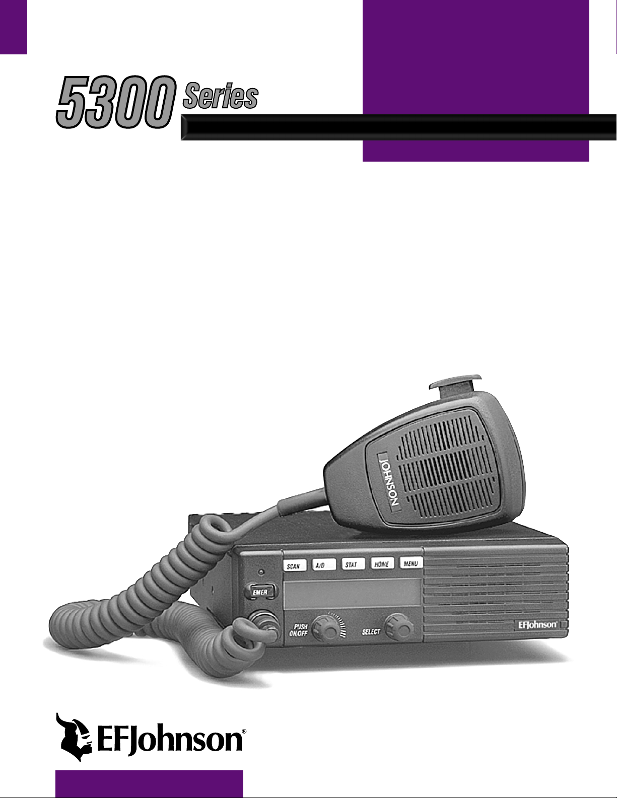
Six Option
PTT Switch
Switches
Display
Multi-function
Indicator
On-Off/
Volume
Figure 2-1 Front Panel Controls
Select
Switch
Microphone
Speaker
2.1 FRONT PANEL CONTROLS
On-Off/Volume - Pressing this contro l tur ns power on
and off, and rotating it sets the volume level.
Select Switch - Selects zones/channels and is also
used for other functions such as selecting names from
a call list. When selecting zones/channels, a bar above
the zone or channel display (see Figure 2-3) indicates
which is being changed. This bar is switched between
displays by pressing this switch, and zone and channels are selected by rotating it (see “Zone/Channel
Select” on page 10).
Multi-function Indicator - This is a two-color LED
that indicates the following:
Red (constant) - Transmitter keyed (PTT switch
pressed).
Green (constant) - Busy condition (car rier detected
in receive mode).
Option Switches - Each of the s ix op tions switches on
the front panel (including the one located to the left of
the display) can be programmed by your system operator to control some function. The switch functions
can be different for each operating mode (conventional, SMARTNET/SmartZone, and Project 25
Trunked). Therefore, up to 18 functions can be
controlled by these switches. Refer to Section 3.8 for
more information on option switch functions.
Speaker - An internal 16-ohm, 5-watt speaker is
located behind the grille. An optional 4-ohm, 12-watt
external speaker may be used if desired. The internal
speaker is disabled when an external speaker is used.
PTT Switch - This push-button switch on the microphone is pressed to talk (key the transmitter) and
released to listen.
Revised August 2002
7
Part No. 001-5300-007CD-NR
Page 8
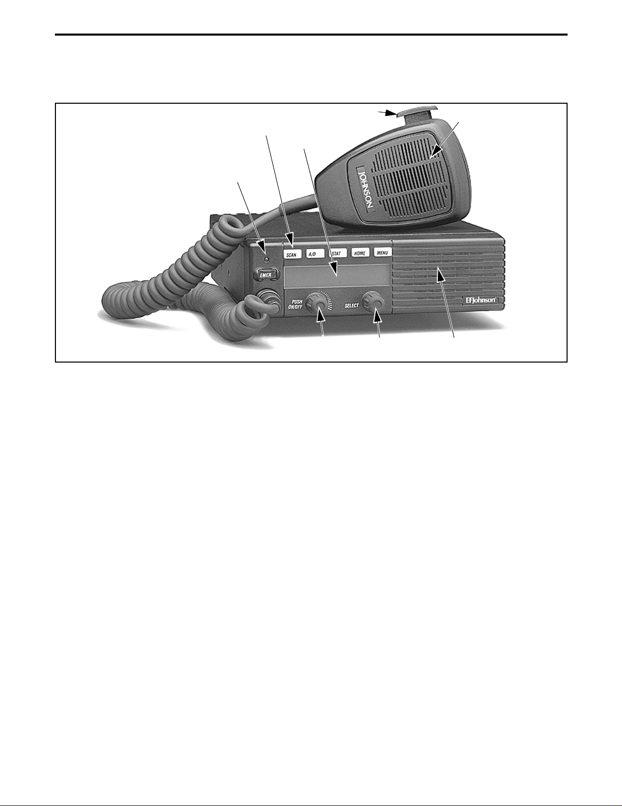
Optional
Remote Control
Unit Jack
Figure 2-2 Rear Panel Jacks
DC Power
Accessory
Jack
CONTROLS AND DISPLAY
Jack
Antenna
Jack
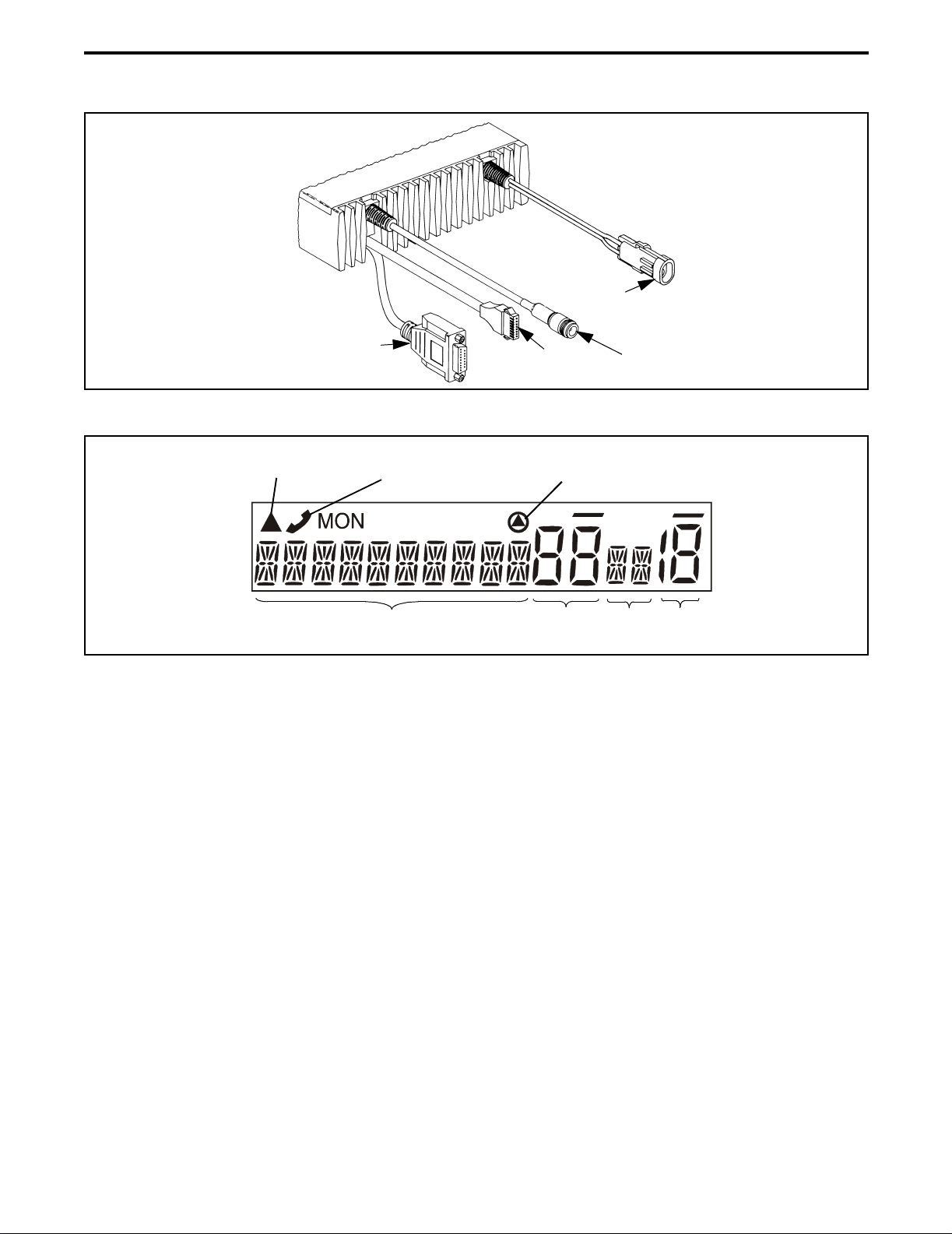
Scan Edit
Mode
Telephone/Special
Call Channel
10-Character Alphanumeric Display
Figure 2-3 Front Pa nel Display
2.2 REAR PANEL JACKS
DC Power Jack - Connection point for the nominal 12volt, negative ground power source (see Figure 2-2).
Antenna Jack - Type N jack for connecting the
antenna.
Accessory Jack - Black connector for connecting
optional accessories such as an external speaker
(4-ohm, 12-watt), horn alert, and ignition sense line.
Remote Control Unit Jack - Connection point for a
remote control unit if used. This cable is optional with
front-mount models.
Encryption
Zone
No.
Status
Display
Chnl
No.
2.3 DISPLAY
Alphanumeric Display - Th is 10-cha racter a rea of th e
display indicates the alias (unique identification) for
the selected zone or channel, depending on which
select mode is active. It may also indicate such things
as the channel frequency, ID numbers, and status and
error messages.
Zone Number - Indicates the currently selected zone
from 1 up to 16. A zone is a co llec tion of cha nne ls tha t
can be any combination of the conventional, P25
Trunked, and SMARTNET/SmartZone types.
Siren Control Jack (Not Shown) - Yellow/orange
connector similar to the accessory jack for connecting
the optional siren controller.
Channel Number - Indicates the currently selected
channel (conventional) or talk group (other modes).
Revised August 2002
8
Part No. 001-5300-007CD-NR
Page 9

GENERAL OPERATION
Stat us Displ ay - These two characters indicate the
following status information:
- This symbol in the left position indicates that
the displayed channel is in the scan list
(scanned normally).
- A “P” in the left position indicates that the
selected conventional channel is a priority
channel.
- This rotating clock-like symbol in the right
position indicates that scanning is enabled.
- When this trian gle is d isp layed, th e scan li st e dit
or keypad programming mode is indicated (see
Section 3.17.5 or Section 4.14).
SECTION 3 GENERAL OPERATION
- Indicates a SMARTNET/SmartZone telephone
call has been initiated. It is non-functional in the
conventional mode.
- Indicates that voice encryption is enabled.
MON - Indicates that the conventional monitor mode
is enabled by taking the microphone off-hook or
pressing the Monitor option switch. This disables
squelch control features so that all messages on the
channel are heard. Refer to Sections 4.2 and 4.3 for
more information.
- The lines above the zone and channel displays
indicate which display is changed if the Select switch
is turned. To switch between displays, press th e Select
switch (see Section 3.6).
3.1 TURNING POWER ON
When power is turned on by pressing the On-Off/
Volume knob, the radio goes through a self test. When
that is successful ly completed, the unit ID is di spl aye d
if applicable, a tone sounds (if tones are enabled), and
the radio is ready for normal operation. If “ENTER
PSWD” is briefly displayed, refer to the next section.
Programming determ in es if the last selecte d or a home
zone/channel is selected at power up.
3.2 POWER-UP PASSWORD
The power-up password feature prevents unauthorized use of the radio by requiring that an 8-digit
password be entered to make it operational. This
feature is enabled or disabled by the PCConfigure
radio programmer.
When this featur e is enable d, “ENTER PS WD” is
briefly displayed when powe r is tur ned on. The 8-d igit
password must then entered by rotating and pressing
the Select switch. In addition, since the logic resets
whenever data is read or written using the PCConfigure programmer, this password must be entered
after performing those functions.
This password can be changed only by the
PCConfigure programmer. It cannot be changed by t he
user. If it is lost, all programming must be erased to
make the transceiver operational again. This is done
using the “EEPROM Erase” function of the PCTune
program. Refer to the Alignment Procedure section in
the 5300 Service Manual for more information.
3.3 BACKLIGHT CONTROL AND DISPLAY
VIEWING ANGLE ADJUST
If the BKLHT option switch is programmed, it
can be used to select high, medium, or off backlight
modes. Otherwise, the key pad and display backlight is
fixed in one of these modes by programming.
If the display is difficult to read from the angle
you normally view it, the viewing angle can be
adjusted as follows: Press and hold the last option
switch above the di splay
switch above the display
and then press the f irst opt ion
. Then release both switches
and turn the Select switch until the best contrast is
obtained. This function times out in 3-5 seconds.
NOTE: If the display appears blank or all icons are
continuously displayed, the viewing angle is probably
improperly adjusted.
Revised August 2002
9
Part No. 001-5300-007CD-NR
Page 10

GENERAL OPERATION
3.4 SETTING VOLUME LEVEL
The relative volume setting can be determined by
noting the positi on o f t he i nde x on t h e On-Off/Volume
knob. Otherwise, enable a reference tone for use in
setting the volume as fo llows:
• If the key pre ss tones are enabled (see Section 3.12
on page 12), a short tone sounds when an option
switch is pressed or the Select switch is pressed or
rotated.
• If a con ventional channe l is selected, tak e the micro-
phone off-hook and if someon e is talking, voice may
be heard. If the
programmed (see Section 4.3 on page 19) , press ing
it unsquelc hes the transceiver and either voice or
background noise is he ard. If a SMARTNET/SmartZone or P25 trunked channel is selected, the transceiver cannot be manually unsquelched.
3.5 ZONE/CHANNEL DISPLAY
The selected zone and channel numbers are
displayed by the zone and channel displays shown in
Figure 2-3 on page 8. In addition, the programmed
zone or channel identification (alias) is displayed in
the alphanumeric display area. The zone alias is
displayed when the zone select mode is enabled, and
the channel alias is displayed when th e channel select
mode is enabled (see next section). With conventional
channels, the channel frequency may be displayed
instead of the alias (see Section 4.9).
A zone can include any mix of up to 16 channels,
and up to 16 zones can be programmed. Therefore, up
to 256 channels can be selected. Zones may be used
for operation in different geographical areas or radio
systems.
3.6 ZONE/CHANNEL SELECT
The front panel Select switch is used to change
the zone and channel. Pressing this switch toggles
between the zone and channel select modes, and
rotating it changes the zone or channel.
The current mode is indicated by the bar over the
zone or channel display. For example, when the bar is
over the zone display (see following illustration), the
zone select mode is enabled.
MON (Monitor) option switch is
Channel Select Indicator
Zone Select In dicator
Zone
No.
Chnl
No.
Rotating the Select switch clockwis e increases
the zone or channel and rotating it counterclockwise
decreases the zone or channel number. After the
highest zone or channel is displayed, wrap-around to
the lowest zone o r c han nel occurs and vice versa. If an
unprogrammed channel is selected,
“UNPROGRAMD” is displayed and a tone sounds.
The transceiver may also be programmed so that only
programmed channels are selected.
The transceiver can be programmed so that the
bar defaults to either the zone or channe l displ ay when
power is turned on and after a change is made. The
delay that occurs before it returns is programmed for
1-15 seconds. It can also be programmed to remain in
the last selected mode.
3.7 SETTING SQUELCH CONTROL
This transceiver does not have a squelch control.
The squelch level is preset and usually does not
require readjustment. However, if the squelch level
needs to be changed on a convent ional anal og channel,
it can be changed using keypad programming if available (see Section 4.14 on page 25).
3.8 OPTION SWITCHES
The six option switches on the front panel (one is
located to the left of the display) can be programmed
by the PCConfigure programmer to control a different
set of functions for each of the three operating modes.
Therefore, up to 18 different functions can be
controlled by these switches (six each for conventional, SMARTNET/SmartZone, and P25 Trunking).
The available functions in each mode and the section
in which each is described are shown in Table 3-1
which follows.
10
Revised August 2002
Part No. 001-5300-007CD-NR
Page 11

Table 3-1 Programmable Option Switch Functions
GENERAL OPERATION
Suggested
Key Label
TONES Alert tones On-Off X X X X
BKLHT Backlight On-Off X X X X
ALERT Call Alert Select X X X
RESP Call Response Select X X X
C/S Clear/Secure Select X X X X
DISP Displayed Information Select X
EMER Emergency Select X X X X
Horn Alert Select X X X X
HOME Home Zone Select X X X X
Hardware (Encrypt) Key Select X
PROG Keypad Programming Select X
MSG Messaging X X
MON Monitor Mode Select X
SEL SQ Normal/Selective Select X
PHONE Phone Call Select* X X
CALL Private Call Select X X
Priority Channel Select X
Remote Access (Pyramid Reptr)
RWS Radio Wide Scan Select X X X X
RT A Repeater Talk-Around Select X
SCAN Scan Select X X X X
SCN ED Scan Edit Select X X X X
Scan List Select X X X
SEL SQ Selective Squelch Code Select X
LOCK Site Lock Select X X
SEARCH Site Search Select X X
STATUS Status Select X X X
TG SEL Talk Group Select X
TX PWR Transmit Power Select X X X X
CALL Unit Call Select X X
(Blank) Unprogrammed (not used ) X X X X
Function
Conv. Proj 25 Trk SMARTNET SmartZone
Available in Mode:
See Descript.
in Section:
3.12
3.3
5.6
5.4.4
3.18
4.9
4.10, 5.9
3.14
3.10
3.18
4.14
5.7
4.3
4.5
5.5
5.4
4.11.4
3.16.3
4.8
3.16.2
3.17.5
3.17.4
4.5
5.13.4
5.13.3
5.8
4.13.4
3.11
4.13.5
3.9 TIME-OUT TIMER
The time-out timer disables the transmitter if it is
keyed for longer than the programmed time. It can be
programmed on each channel for times from 15
seconds up to 3 minutes, 45 seconds or it can be
disabled. If the transmitter is keyed continuously for
longer than the programmed time, the transmitter is
disabled, a continuous tone sounds, and “TX
TIMEOUT” is displayed. Five seconds before timeout occurs, a warning beep sounds to indicate that
time-out is approaching. The timer and tone are reset
by releasing the PTT switch. A different time can be
programmed for each system, and the timer can be
enabled or disabled on each channel.
One use of this feature is to prevent a channel
from being kept busy for an extended period by an
accidentally keyed transmitter. It can also prevent
possible transmitt er damage c aused by t ransmitti ng for
an excessively long period.
Revised August 2002
11
Part No. 001-5300-007CD-NR
Page 12

GENERAL OPERATION
3.10 HOME ZONE/CHANNEL SELECT
If the HOME zone option switch is programmed,
pressing it selects the preprogrammed home zone and
channel. This provides a quick way of returning to a
frequently used zone and channel. The transceiver is
also programmed so that either the home or last
selected zone/channel is automatically selected when
power is turned on.
3.11 POWER OUTPUT SELECT
Each conventional channel and SMARTNET/
SmartZone and P25 Trunked system can be
programmed for High, Low, or Switchable transmit
power. If Switchable power is programmed on the
channel, the
to select high or low transmitter power. All models
support switchable power.
Pressing the
setting. The new level is flashed in the display when
this switch is pressed as “HI POWER” or “L OW
POWER”. If selectable power is not permitted on the
current channel, the fixed power level is flashed as
“FIXED HIGH” or “FIXED LOW” and no power
change occurs. The selected power level for a channel
is permanent until it is manually changed again.
Tx PWR option switch can then be used
TX PWR switch toggles the power
Both the ignition switch and the power switch
must then be on for transceiver power to turn on. The
delay can be overridden at any time by turning power
off using the front panel power switch or turning the
ignition switch back on.
This turn-off delay can allow calls to be r eceived
or the horn alert to be active for a time after the ignition switch is turned off. At the same time, advantages
of ignition switch control are utilized such as
preventing the battery discharge that may occur if the
transceiver is left on for an extended period (see
Section 6.5).
3.14 HORN ALERT
The horn al ert feature sounds an ext ernal alert
such as the vehicle horn when certain calls are
received. It is available if a Horn option switch is
programmed and the proper connecti on has been made
to the external alert. The horn alert output is pin 4 of
the accessory cable, and an external driver circuit of
some type is usually required. Refer to the Installation
section of the 5300 Service Manual for more information on how to install this feature.
Additional information on the horn alert feature
follows:
3.12 ALERT T ONE SELECT
The various alert tones that sound are described
in Section 6.1 on page 35. These tones can be enabled
and disabled if the
programmed. To turn all tones off, press this switch
and “TONE OFF” is displayed. Then to turn all tones
on again, press it and “TONE ON” is displayed. If this
switch is not programmed, tones are fixed in the on or
off condition by programming.
3.13 POWER TURN-OFF DELAY
The transceiver can be installed so t hat the
vehicle ignition switch as well as the front panel
power switch of the transceiver control power. This is
done by connecting the ac cessory cable ignition swit ch
input to the vehicle ignition switch. Refer to the Installation section of the 5300 Service Manual for more
information. A power-off delay of up to 254 minutes
or forever can then be programmed.
TONE option switch is
• It activates when receiving any Unit call in the
conventional mode and any Private/Unit and Call
Alert (paging) call in the SMARTNET/SmartZone
and P25 Trunked modes. It does not sound when
receiving standard Group or Telephone calls, and is
not programmable on a per call basis.
• It must be manually enabled and disabled by the
Horn option switch. It is not controlled by the
vehicle ignition switch. When it is enabled, “HORN
ON” is briefly displayed, and when it is disabled,
“HORN OFF” is briefly displayed. It def aults to the
off mode whenever power is turned on.
• If a power turn-off delay is programmed as just
described, it is functional dur ing that del ay.
• When activa ted, i t can be progra mmed to soun d for
three 1-second beeps or continuously for 2-90
seconds. It then turns off until another call is
received.
12
Revised August 2002
Part No. 001-5300-007CD-NR
Page 13

GENERAL OPERATION
3.15 MICROPHONE OFF-HOOK DETECT
The microphone hanger can be connected to
chassis ground and the radio programmed to detect an
off-hook condition (Hangup Box Monitor selected).
The following operation then occurs when the microphone is taken off-hook :
Conventional Channel Selected
rarily halts (if applicable) and the Monitor Mode
described in Section 4.3 is enabled. However, the
receiver unsquelches only if a carrier is detected.
SMARTNET/SmartZone/P25 Trunked Channel
Selected - Scanning temporarily halts if applicable.
If the off-hook condition is not detected (Hangup
Box Monitor not selected), the microphone hook state
has no affect on radio operation.
- Scanning tempo-
3.16.2 STANDARD SCANNING
Standard scanning monitors only channels that
are the same type as that currently selected. For
example, if a conventional channel is selected, only
conventional channels are scanned and likewise for
SMARTNET/SmartZone and Project 25 trunked
channels. For more information on scanning functions
unique to these operatin g modes, ref er to Secti ons 4.1 1
and 5.11. Standard scanning operates as follows.
• To turn standard scanning on, press the SCAN
option switch. Scanning is enabled when a rotating
is indicated in the right status display as follows
and “SCAN ON” is briefly displayed.
Scan Enable Indicator
3.16 SCANNING
3.16.1 INTRODUCTION
Scanning monitors the channels in the scan list
for messages the t ransceiv er is pr ogrammed to receive .
When a message is detected, scanning stops and the
message is received. Shortly after the message is
complete, scanning resumes (unless it has been
disabled).
If the microphone off-hook condition is detected
(Hangup Box Monitor selected by programming),
scanning stops and selective squelch (such as Call
Guard CTCSS or NAC/group ID detect ) is di sable d on
conventional channe ls . If t he off-hook condition is not
detected, taking the micr ophone of f-hook has no af fect
on transceiver operation.
There are two scan modes available: Standard and
Radio Wi de. The standard type is unique t o t he t ype of
channel selected, and the Radio Wide type is the same
for all channel types. Onl y one type of scanni ng can be
enabled at a time. Therefore, if standard scanning is
enabled when the Radio Wide Scan switch is pressed,
standard scanning is automatically disabled and vice
versa. Refer to the following for more information.
• To turn s canning of f, press the SCAN option switch
again. On conventional channels, this may also
select another list, so several presses may be
required (see Section 4.11). Scanning is disabled
when “SCAN OFF” is briefly di splayed and is no
longer indicated in the status display.
• If the zone or channel is changed while scanning is
selected, scanning continues on the same or a
different scan list (see Section 3.17.1).
NOTE: Each SMARTNET/SmartZone and P25 trunked
channel can be programmed so that scanning is automatically enabled when the channel is selected.
3.16.3 RADIO WIDE SCANNING
NOTE: Use radio wide scanning only if two types of
channels need to be scanned at the same time such as
conventional and SMARTNET/SmartZone. Otherwise,
use the more ef ficient sta ndar d sc anning because there
is less chance of missed calls.
Radio wide scanning mon itors the ch anne ls in the
preprogrammed radio wide scan list. This list may
contain up to 16 channels of any type assigned to any
13
Revised August 2002
Part No. 001-5300-007CD-NR
Page 14

GENERAL OPERATION
zone (see scan list description in Section 3.17.1).
Radio wide scanning is turned on and off by the
option switch as follows. If this switch is not
programmed, radio wide scanning is not available.
RWS
• To turn radio wide scanning on, press the RWS
option switch and “RSCN ON” is b riefly displayed.
In addition, is displayed the same as with standard scanning.
• To turn radio wide scanning off, press the RWS
option switch again and “RSCN OFF” is briefly
displayed and is no longer displayed.
• If the zone or channel is changed while radio wide
scanning, scanning continues normally.
3.16.4 SCAN RESUME DELAY
When a message is received or transmitted while
scanning, there is a delay before scanning resumes.
The delay after receiving a call prevents another
message from being received before a response can be
made. The delay after trans mit ting a ca ll ensu res tha t a
response is heard ins tead of another mess age occurring
on some other channel.
Separate delay times are programmable for radio
wide and standard scanning. With radio wide and
conventional standard scanning, delays of 0-7.5
seconds are programmable in 0.5-second steps. With
SMARTNET/ SmartZone standard sc anning, a delay of
2-10 seconds can be programmed in 0.5-second steps.
3.16.5 TRANSMITTING IN THE SCAN MODE
If the transmitter is keyed while scanning is
enabled, transmissions occur on various channels as
follows.
Conventional Operation - Transmissions can occur on
the priority, selected, or receive channel. Refer to
Section 4.11 for more information.
3.16.6 NUISANCE CHANNEL DELETE
With standard scanning, channels can be temporarily deleted from the scan list, for example, if
messages on a channel become annoying. This feature
is not available with radio wide scanning. Channels
can also be permanently added or deleted by editing
the scan list as described in Section 3.17.5. Proceed as
follows to temporarily delete a channel:
NOTE: The selected channel and also conventional
priority channels cannot be deleted from the scan list.
1. While receiving a message on the channel to be
deleted, press and hold the
until a tone sounds (approximately 2 seconds).
2. The channel is then deleted and scanning of the
remaining channels in the scan list resumes.
3. Deleted channels are added back into the scan list if
any of the following events occur:
SCAN option switch
• Scanning is tur ned off and the n on again using the
SCAN switch.
• Trans ceiver power is turned of f and then on again.
• The scan list is reselected by changing channels
(SMARTNET/SmartZone) or using the
option switch (conventional).
3.17 SCAN LISTS
NOTE: A scan list is simply the channels that are
scanned when scanning is enabled.
3.17.1 STANDARD MODE SCAN LISTS
NOTE: The selected channel is always scanned.
With all operating modes, as many standard scan
lists as are required can usually be programmed (up to
256). The only limitation is the availabl e memory.
Each list can include up to 256 channels/talk groups.
SCAN
SMARTNET/SmartZone Operation - If scanning is
halted to receive a message, programming determines if transmissions occur on the selected or
receive channel . T ran smissions at othe r times occur
on the selected channel.
Scan List Select
which follows for inform ation on selecting a scan list.
Scan List Edit
which follows for inform ation on editing a scan list.
14
- Refer to “Selecting a Scan List”
- Refer to “Programming a Scan List”
Revised August 2002
Part No. 001-5300-007CD-NR
Page 15

GENERAL OPERATION
3.17.2 RADIO WIDE SCAN LIST
With radio wide scanning, there is only one scan
list and it can include up to 16 channels of any type.
For example, it could include six conventional channels and ten SMARTNET/SmartZone channels. The
channels in this list are not user programmable.
3.17.3 DETERMINING WHICH CHANNELS ARE
IN SCAN LIST
Channels in the radio wide and conventional standard scan lists are determined as follows. Channels in
the SMARTNET/SmartZone and P25 Trunked standard scan li sts are indicated only when editing a l ist.
1. Enable Standard scanning to view the standard list
or Radio W ide scann ing to view the radio wide scan
list (the procedure is on page 13). Also select the
scan list if applicable as described in the following
“Selecting a Scan List” description.
2. Select the desired zone and then scroll through the
channels by rotating the Select switch. When the
displayed channel is in the scan list (scanned
normally), the symbol is displayed next to the
zone number as shown in the following illustr ation.
1. Make sure that both standard and radio wide scanning are off (the rotating icon is not indicated in
the right status display). Select a conventional,
SMARTNET/SmartZone, or P25 Trunked channel
corresponding to the scan list being edited.
2. Select the scan list edit mode by pressing the
option switch. This mode is indicated by a
ED
SCN
triangle in the upper left corner of the display (see
Figure 2-3 on page 8.).
3. If appli cable, select the list to be e dited by rota ting
and then pressing the Select switch. The selected
scan list is indicate d as “LIST x” as descr ibed in the
preceding section. If user programming is disabled
on a list, “NO EDIT” is momentar ily di splay ed and
it cannot be edited (conventional channels only).
4. Select the channel you want to add or delete by
rotating the Select switch. After the last channel i n
the current zone is disp layed, the fi rst valid channel
in the next zone i s displayed and vice v ersa. Lists are
limited to 256 channels . If an attempt is made to add
more than 256, “LIST FULL” is displayed and a
channel must be deleted before another can be
added.
Scan List Indica tor
Chnl
No.
3.17.4 SELECTING A SCAN LIST
Conventional Operation - The scan list is user selectable by the
SCAN option switch. Refer to Sect ion 4.11
for more information.
SMARTNET/SmartZone
/P25 Trunked Operation The scan list can be temporarily changed if the Scan
(List) Select option switch is programmed. Refer to
Section 5.11 for more information.
3.17.5 EDITING A SCAN LIST
If the SCN ED (Scan Edit) option switch is
programmed, standard scan lists can be user edited as
follows (all operating modes):
NOTE: A conventional priority channel cannot be
deleted (see Section 4.11.4).
5. If the selected channel is in the scan list (scanned),
the symbol is displayed next to the zone number
as described on page 15. To change the scan list
status of the displayed channel, press the Select
switch.
With conventional channels only, if the selected
scan list is programmed with a fixed priority
channel (see Section 4.11.4), the next press of the
Select switch makes the current channel the priority
channel. The “
P” is then indicated in the left status
display next to the z one number t o indicat e that it i s
a priority channel. Pressing the Sel ect switc h again
takes the channel out of t he scan list.
6. To exit this mode and save the changes, press the
SCN ED option switch again.
15
Revised August 2002
Part No. 001-5300-007CD-NR
Page 16

GENERAL OPERATION
3.18 SECURE COMMUNICATION
3.18.1 INTRODUCTION
This transceiver may be equipped to provide
secure communication on some or all channels. This
feature encrypts the voice so that it can be understood
only by someone using a transceiver equipped with a
similar encryption device and encryption codes.
When a secure call is received or transmitted,
is indicated in the display. If equipped with the
Clear/Secure option switch and the current channel is
programmed to allow switch selection, secure communication can be manually enabled and disabled by that
switch. Otherwise, channels are strapped to Clear or
Coded operation. Secure communication can be
programmed on a per channel basis to operate in
various ways. Refer to the following for more information:
3.18.2 CONVENTIONAL CHANNELS
On conventional analog channels, the protocol
that can be used to provide secure communication is
SecureNet™ DES or DES-XL encryption.
or DVP algorithm. The SecureNet protocols include
the followin g:
• DVP (Digital Voice Privacy) is an earlier encryption
method that is sel f synchronizing using cip her f eedback. It was originally designed to be used by
anyone needing protection from unauthorized
eavesdropping.
• DES (Data Encryption Standard) provides the
highest level of security, and also uses cipher feedback. It was originally designed to be used only by
the Federal government.
• DVP-XL/DES-XL - A disadvantage of the DVP and
DES encryption types is reduced communication
range when compared to clear voice. The DES-XL
and DVP-XL methods were designed to provide
better range but at the cost of lower voice quality.
They use a different type of fe edback called counter
addressing.
• DES-OFB - A form of DES encryption for digital
channels that uses output feedback. This protocol
does not result in the degraded range that occurs
with analog channels.
On conventional di gita l (Pr oject 25) c han nels, the
SecureNet DES-OFB protocol is used. In the receive
mode, clear and secure messages are always automatically detected.
3.18.3 SMARTNET/SMARTZONE AND P25
TRUNKED CHANNELS
On SMARTNET/SmartZone analog channels,
SecureNet DES or DES-XL protocol can be selected.
On SMARTNET/SmartZone and P25 Trunked digital
channels, only the DES-OFB protocol is available.
Talk groups can be strapped to Clear, Coded, or
Switch selectable, and clear and secure messages are
always autodetected.
The following calls require their own encryption
key selection: emergency, failsoft, patch, telephone,
private, and system-wide.
3.18.4 SECURENET
SecureNet is a proprietar y Motorola protocol that
digitizes the voice and then encrypts it using the DES
The transmission mode (DES/DES-XL) is
selected by the programming software for each
SecureNet analog channel . If a channel is pr ogrammed
for DES-XL, it will also receive DES, but transmissions always occur in DES-XL.
3.18.5 HARDWARE (ENCRYPTION) KEYS
General
NOTE: A constant power supply must be connected to
the transceiver to maintain the encryption keys in
memory . Th erefor e, i f eq uip ped with these keys, do not
remove th e radio f r o m batt ery power or disco nnect t he
battery for extended periods (typically 8 hours or
more).
Each SecureNet channel is assigned a hardware
key from 0-15. This is the hardware location of the
encryption key to be used. The keys in these locations
are loaded into the radio using the Motoro la or PC key
loader. The keyloader converts an input of approximately 20 characters into the “key” that is loaded into
16
Revised August 2002
Part No. 001-5300-007CD-NR
Page 17

GENERAL OPERATION
the radio. There is a maximum of 16 keys that can be
loaded into the radio at one time.
NOTE: There is a security feature that automatically
erases the encryption keys when the bottom cover is
removed. This function is performed by a push button
switch S1 on the logic board.
As stated in the above “NOTE”, the transceiver
must be connected to an unswitched power source to
preserve the encryption keys in memory. However,
there is a storage capacitor (C173, 0.22 µF) which
maintains the 5-volt supply (and the encryption keys)
for a minimum of approximately 8 hours if power is
temporarily lost.
If an attempt is made to transmit a secure
message without loading the corresponding key,
“KEYFAIL” is displayed. The message must then be
transmitted in the clear mode (this is possible only if
the channel is strapped to “switchable” as described
below) or the key must be loaded.
SecureNet Key Selection
clear mode by programming, and in the SecureNet
mode if it has been strapped (fixed) to SecureNet. If
the channel has been strappe d to “swit ched”, t he mode
is selected by the Clear/Secure option switch. When a
message is receive d or tr an smitted in the secure mode,
is displayed.
If the channel has been strapped “Clear” and the
option button selects the “Secure” mode on power up
and a transmission is attempted, “Clear Only” is
displayed and transmitting is disabled. Conversely, if
the channel is stra pped “Sec ure” and the option button
selects the “Clear” mode on power up and a transmission is attempted, “Secure Only” is displayed and the
transmitter is disabled.
3.18.7 460 SCRAMBLING
The 460 Scrambling protocol is a proprieta ry
Transcrypt protocol that is compatible with the standalone scrambling option from Transcrypt. The 460
type of scrambling is no longer available with 5300
transceivers.
NOTE: This feature is available on conventional
channels only.
When multiple hardware keys are programmed
(see preceding information), the Hardware Key Select
option switch can b e programmed to al low selec tion of
another key for the channel. This feature permanently
selects another key for the channel (cycling power or
selecting a different channel does not reselect the original key). Therefore, to swi tch back to th e original key,
it must be manually reselected. Proceed as follows to
select a key:
1. Press the Hardware Key Select switch and HWKEY
x is displayed. The “x” indicates the current key
selection from 0-15.
2. Rotate the Select switch to display the desired key
and then press the Sele ct switch to select it. Press the
Hardware Key Select switch again to return the
display to normal operation.
3.18.6 CLEAR/SECURE STRAPPING
3.18.8 TRANSMIT MODE OPTIONS
The following transmit options are available
when SecureNet encryption is selected:
Clear - All calls are in the clear mode unless
responding to a secure call. If the response is then
made within the delay time (see Section 3.16), it
occurs in the secure mode.
Coded - All calls are made in the selected secure
mode.
Switched - The mode is selected by the Clear/Secure
switch. When the clear mode is selected by this
switch, “CLEAR” is flashed, and when the secure
mode is sel ected, “SECURE” is flashed.
3.18.9 RECEIVE MODE OPTIONS
With the SecureNet protocol, the following
receive options can be programmed:
Transmissions on an analog channel are in the
clear mode if the channel has been strapped to the
No Autodetect - Only signals co ded like the transmit
signals are received.
Revised August 2002
17
Part No. 001-5300-007CD-NR
Page 18

GENERAL OPERATION
Secure Autodetect - Both clear a nd Secur eNet s ignals
are automatically detected. This mode is automatically selected if the trans mi t mode is switc h sele ct abl e.
Proper Key Autodetect - An incoming SecureNet
call is compared against all of the available keys
programmed into the radio. If a match is found, the
call is decrypted using matched key.
3.19 TRANSCEIVER OPERATING MODES
3.19.1 GENERAL
Each selectable channel can be programmed for
the conventional, SMARTNET/SmartZone, or Project
25 (digital) trunked operating mode. For example,
Zone 1/Channel 1 could be a conventional channel,
Zone 1/Channel 2 a SMARTNET channel, and so on.
Consult your system operator to determine the type or
types of operation programmed in your transceiver.
More information on these modes follows.
3.19.2 CONVENTIONAL MODE
This is a non-trunked operating mode which
accesses independent radio channels (there is no automatic access to several channels). Selecting a conventional channel selec ts a tr ans mit and re ceive freque ncy
and other channel parameters such as squelch control
coding.
Conventional channels can be either standard
(analog) or Project 25 (digital). With digital operation,
the DSP (Digital Signal Processor) converts the audio
signal to digital data which is sent over the air as
complex tones. Another difference is that analog channels use Call Guard (CTCSS/DCS) squelch control
and Project 25 channels use a NAC (Network Access
Code) and talk group ID codes.
With NAC, a number similar to an ID code is
transmitted, and for communication to occur, it must
match one programmed in the base equipment and the
mobile(s) being called. In addition, to receive standard group calls, the receiving mobile(s) must be
programmed to detect the transmitted ID code.
lockout (transmit disable on busy) feature is
programmed. Otherwise, it must be detected manu ally.
An out-of-range condition is not indicated by special
tones or messages as with SMARTNET operation
because there is no initial data exchange with the
repeater that allows this condition to be detected.
Operating features unique to conventional channels
are described in Section 4.
3.19.3 SMARTNET/SMARTZONE MODE
This is a trunked operating mode in which automatic access is provided to several RF channels. ID
codes are used to select what mobiles are being called
and what calls are recei ved. Monitoring is perfo rmed
automatically and special messages and tones indicate
busy and out-of-range conditions.
SMARTNET and SmartZone operation and
programming is very similar. Basically, SMARTNET
operation is limited to a single repeater site and SmartZone operation allows automatic roaming between
sites. Enhanced features incl ude roa ming (Smar tZone
only), telephone, private, and emergency calls, Call
™
Alert
, and messaging. Either analog or digital
signaling may be used.
When a SMARTNET or SmartZone channel is
selected or the radio is powered up on one of those
channels, it searches for a control channel. Once a
control channel is found, the alias (name) of the
selected channel is displayed and the radio attempts to
register on the ra dio system. If a control channel could
not be found (because of an out of range condition or
the system ID is not correct, for example), “NO SYS”
is displayed and the radio continues to search for a
control channel.
The control channel transmits and receives
system information to and from all radios register ed on
the system. Therefore, once a contro l channel i s found,
it is continuously monitored for incoming call information and is used to make call requests. The radio
automatically chang es t o a tra ffic channel to place and
receive calls and then returns to the control channel
when the call is complete.
With conventional operation, a busy channel
condition is detected automat ical ly if the busy cha nnel
Operating features unique to SMARTNET/SmartZone channels are described in Section 5.
18
Part No. 001-5300-007CD-NR
Revised August 2002
Page 19

CONVENTIONAL FEATURES
3.19.4 P25 TRUNKED MODE
The P25 Trunked operating features are very
similar to the SmartZone type just described. Therefore, these modes plus SMARTNET are all described
in the same section (Section 5). Some diffferences
between the P25 Trunking and SmartZone modes are
as follows:
• Digital signaling is always used with P25 calls.
Either analog or digital signaling may be used for
SmartZone calls.
• Calls made to a specific mobile in the P25 mode are
called Unit Calls. In the SmartZone mode they are
called Private Calls.
• Messaging is not available with P25 calls.
SECTION 4 CONVENTIONAL FEATURES
4.1 INTRODUCTION
• P25 Trunked telephone calls are not be available
until a future release.
• The P25 control channel data rat e is 9600 baud and
the digital voice data rate is also 9600 baud. With
SmartZone operation, the control channel data rate
is 3600 baud (both digital and analog calls) and the
narrowband digital voice data rate is 9600 baud.
• The P25 mode uses a system ID, a Wide Area
Communications Network (WACN) ID, and an RF
Subsystem ID (RFSS). The SmartZone mode does
not use the WACN and RFSS IDs.
• P25 Unit IDs can be 1-16,777,215 (000001-FFFFFF
hex) and SmartZone Unit IDs can be 1-65,535
(0001-FFFF hex).
Manual Channel Monitoring
An overview of the conventional operating mode
is located in Section 3.19.2. The fol lowing informat ion
describes the features unique to conventional standard
(analog) and Project 25 (digital) operation. Refer to
the preceding “General Operation” section (Section 3)
for information on features common to all operating
modes.
4.2 MONITORING BEFORE TRANSMITTING
With conventional operation, you may need to
manually monitor the channel before transmitting to
make sure that it is not being used by someone else. If
you were to transmit whil e someon e else was u sing the
channel, you would probably disrupt their conversation. With the trunked operating modes, channel monitoring is performed automatically. Monitor conventional channels automatically or manually as follows:
Automatic Channel Monitoring
If the selected channel is programmed for Busy
Channel Lockout (also called Transmit Disable On
Busy) feature, monitoring is performed automatically.
Refer to Section 4.4 for more information on this
feature.
The automatic monitoring just described may
occasionally disable the transmitter when the channel
is not in use, such as when the repeater has extended
hang time. In this case, you may not want to use it and
the channel must then be monitored manually as
follows:
Busy Indicator - With scanning disabled, note if the
multi-function indicator on the front panel is steady
green. If it is not, the channel is not being used and
you can transmit your call. If it is green, a carrier is
being detected, so the channel may be busy (see next
paragraph).
Monitor Mode - There may be times when the busy
indication is displ ayed ev en thoug h no o ne is us ing th e
channel. Monitoring should then be performed by
disabling Call Guard squelch (or group ID detect on
P25 channels). This is usually done by selecting the
Monitor Mode (see following).
4.3 MONITOR MODE
The monitor mode unsquelches the receiver even
if a carrier is not detect ed. Therefore , it can be used for
such things as monitoring a channel for all activity
19
Revised August 2002
Part No. 001-5300-007CD-NR
Page 20

CONVENTIONAL FEATURES
before transmitting or improving reception when intermittent squelching makes messages hard to understand. Other Monitor mode features are as follows:
• Call Guard (CTCSS/DCS) squelch is disabled on
analog channels and NAC and group ID detect are
disabled on P25 (conventional) channels.
• Busy Channel Lockout is overridden (see next
section)
• Scanning temporarily halts
The Monitor Mode is selected as follows:
1. Briefly press the
The display then indicates “MON” (see Figure 2-3
on page 8) and the receiver un squelches.
2. To disable the monitor mode and return to normal
operation, press the
3. In the scan mode, pressing and holding the
option switch monito rs the scan ned channel instead
of the selected channel (if it is different).
Taking the microphone off-hook also selects the
Monitor mode if off-hook detection is enabled (see
Section 3.15). Pressing the
disables Call Guard squelch/P25 group ID detect but
not scanning and P25 NAC detect (see Section 4.5).
4.4 BUSY CHANNEL LOCKOUT
MON option swit ch (i f available).
MON option switch again.
MON
SEL SQ option switch
Tone (NAC) - If an incorrect Call Guard (CTCSS/
DCS) or P25 NAC code (see Section 1.4) is detected,
the transmitter is disabl ed when the PTT switch is
pressed. An incorrect code is any code other than the
one programmed for the current channel.
If Busy Channel Override is permitted by
programming, it is possible to transmit even when the
transmitter is disabled by this feat ure . Simply rel ea se
the PTT switch and then quickly press it again.
4.5 CALL GUARD SQUELCH
4.5.1 INTRODUCTION
Tone or digital Call Guard squelch (also called
CTCSS/DCS signaling) can be programmed on each
conventional analog transmit and receive channel in
any order desired. The reverse burst and turn-off code
are always transmitted and also detected on channels
programmed with Call Guard squelch.
The Call Guard squelch feature eliminates
distracting messages intended for others using the
channel. This is done by using a subaudible tone or
digital code to contr ol th e s quelch . This ton e or c ode is
unique to a user or a group on that channel. This tone
or code is transmitted with the voice signal but is not
heard because it is i n the subaudible range and is att enuated by a filter. Call Guard squelch must be used in
both the transmitting and receiving transceiver to be
functional.
The Busy Channel Lockout (also called Transmit
Disable on Busy) feature automatically disables the
transmitter if the channel is busy when the PTT switch
is pressed. When the transmitter is dis abled by this
feature, “BUSY” is displayed , a busy tone sounds, and
the transmitter is disabl ed.
The Busy Channel Lockout feature can be
programmed to operate as follows. Each conventional
channel can be programmed differently.
Off - Busy channel lockout is disabled and the transmitter keys even if the channel is busy.
Noise - If a carrier is detected on the channel, the
transmitter is disabled w hen the PTT switch is pressed.
4.5.2 CALL GUARD SQUELCH ENABLE/
DISABLE
The SEL SQ option switch (if programmed) can
be used to disable receive Call Guard squelch on
analog channels or group ID code detect on P25 channels. When selective squelch is disabled, “NORMAL”
is flashed in the display, and when it is enabled,
“SELECTIVE” is flashed.
When “Normal” is selected, the receiver
unsquelches only if a carrier is detected, and scanning
and P25 NAC detection are not disabled. The selected
mode remains in effect until it is manually changed.
Selecting another channel or cycling power does not
reselect a default condition.
Revised August 2002
20
Part No. 001-5300-007CD-NR
Page 21

CONVENTIONAL FEATURES
4.5.3 TONE CALL GUARD SQUELCH
Tone-type Call Guard squelch utilizes subaudible
CTCSS tones from 67-254.1 Hz. Although th ere are 42
tones assigned, thos e above 33 (210.7 Hz) are normall y
not used because of their close proximity to the voice
band which starts at 300 Hz. In add ition, tones 1 1 (97.4
Hz), 39 (69.3 Hz), 40 ( 206.5 Hz), 41 2 29.1 Hz), and 42
(254.1 Hz) are normally not used because they may
cause interference with adjacent tones.
A reverse burst is transmitted when the push-totalk switch is re lease d and al so dete cte d when cal ls ar e
received. It is a 180-degree phase reversal for a period
of time determined by the tone frequency, and it eliminates the squelch tail (noise burst) in the receiving
transceive r. Both the transmitting and receiving transceiver must be equipped with this feature for it to be
utilized.
4.5.4 DIGITAL CALL GUARD SQUELCH
Digital Call Guard sque lch (CDCSS) uses digita l
data instead of subaudi ble t ones t o cont rol t he sque lch.
This data consists of continuous repetitions of 23-bit
words. No bit or word synchronization information is
used. When the push-to- talk switch is released, a t urnoff code is transmitted which eliminates the squelch
tail similar to the reverse burst.
Although there are thousands of possible code
combinations with 23 bits, only 83 are uniqu e wi th th e
data scheme used. The number specified when the
code is programmed is actually a seed for a specia l
algorithm used to generate the 23-bit data word. The
data is transmitted at a rate of 134.4 bits per second.
Therefore, approximately six words are transmitted
each second. When the da ta is dec oded, 23-bit samples
are taken and then the bit s ar e r o ta te d to determine if a
valid code was received.
4.5.5 SELECTING CALL GUARD CODE
NOTE: Call Guard codes may be permanently reprogrammed by keypad programming (see Section 4.14).
programmed. This feature allows the normal transmit
and receive Call Guard programming to be temporarily overridden with a code selected from this list.
The CTCSS/DCS/NAC list is programmed with
up to sixteen tone (CTCSS) or digital (DCS) Call
Guard codes. In addition, for operation on Project 25
channels, each position can be programmed with an
NAC code.
When the Call Guard code is changed using this
feature, it remains selected even if other channels are
selected. When scanning, the selected code also
applies to all scanned channels. If both analog and
digital (Project 25) channels can be selected or
scanned, the CTCSS/DCS code for the selected position is used for analog channels and the NAC code for
the selected position is used for P25 channels. If a
channel is programmed for mi xed mod e ope rat i on, the
selective squelch type (analog or digital) programmed
for the transmit m ode det ermines the selective squelch
type used.
Proceed as follows to select a preprogrammed
Call Guard code:
1. Press the Squelch Code Select option switch and
then rotate the Select switch to select the desired
position. The display indica tes “SEL SQ xx” where,
“xx” is the selected code from 1-16.
2. T o select the disp layed code and retu rn to the normal
display , press the Squelch Code Select s witch again.
3. To check which code is selected, press the Squelch
Code Select switc h once to displ ay the curren t selection and then again to return to normal operation.
4. To return to the normal selective squelch codes,
select “DEFAULT” in this mode. The n ormal codes
are also automatically reselected whenever transceiver power is cycled or a talk-around channel is
selected.
4.6 PENALTY TIMER
A different CTCSS/DCS/NAC squelch code can
be temporarily selected if the Squelch Code Select
option switch and a CTCSS/NAC code list have been
A penalty timer may be programmed on conventional channels to prevent transmissions for a short
period of time after the time-out timer disables the
Revised August 2002
21
Part No. 001-5300-007CD-NR
Page 22

CONVENTIONAL FEATURES
transmitter (see Section 3.9). The penalty timer starts
when the PTT switch is released after the transmitter
has been disabled. If the PTT switch is pressed during
the penalty time, the time-out indication occurs again.
When the penalty ti mer exp ir es, a beep sounds and the
transmitter can then be keyed.
4.7 CONVERSATION TIMER
A conversation timer can be programmed on
conventional systems in addition to the time-out timer
(see Section 3.9). This timer limits that total length of
a conversation rather than just the length of each transmission as with the time-out timer. The following is
more information on this timer.
• It can be programmed for times up to 7.5 minutes.
• It is reset when th e time between transmissions
exceeds the time programmed for the penalty timer.
• A warning beep sounds 5 seconds before this timer
disables the transmitter.
• When this timer disables the transmitter, a contin-
uous tone sounds and the red transmit indicator
turns off. The PTT switch must then be released
until the penalt y timer e xpires ( indic ated by a b eep).
4.8 REPEATER TALK-AROUND
Normally, all transmissions go through a repeater
which usually increases ran ge. Howev er, there may be
times when a mobile is ou t of ra nge of the repe ater and
therefore unable to talk to anyone even though the
mobile being called is only a short distance away. To
allow communication in this situation, repeater ta lkaround can be selected. Transmissions then occur on
the receive frequency which permits direct mobile-tomobile communication.
4.9 DISPLAYING TRANSMIT/RECEIVE
FREQUENCY
If the DISP option switch is programmed, it can
be used to display the chann el frequen cy in megahert z.
Pressing this switch toggles between displaying the
standard channel alias and the frequency. The receive
frequency is displayed while receiving and the
transmit frequency is displayed while transmitting.
This feature is available on conventional channels
only.
4.10 EMERGENCY MODE
An EMER option switch may be progra mmed on
conventional channel s to alert a dis patcher or someone
else of an emergency condition.
When this switch is pressed with a Project 25
(digital) channel selected, all transmissions have the
emergency flag set. Scanning is disabled and the transceiver remains in the emergency mode until power is
cycled.
Emergency conditions are not transmitted when
an analog channel i s s el ect ed. However, if it i s p re sse d
on an analog channel and a Project 25 channel is
selected before power is turned off, the emergency
condition is transmitted on the Project 25 channel as
just described.
4.11 CONVENTIONAL MODE SCANNING
4.11.1 GENERAL
Channel scanning features common to all operating modes are described in Sections 3.16 and 3.17.
The following information describes features unique
to conventional operation.
4.11.2 SELECTING A SCAN LIST
Repeater talk-around can be selected if the RTA
option switch is programmed. When talk-around is
enabled by this switch, “ RTA ON” is fl ashed in the
display, and when it is disabled, “RTA OFF” is
flashed. This feat ure r emains enabl ed dur ing sc anning ,
and changing channels or turning power off does not
change the selec ted condi tion. Talk-ar ound is a vailable
on conventional channels only.
Conventi onal mode sc an lists are selected by
repeatedly pressing the Scan option switch. For
example, if three scan lists are programmed, the first
press of the Scan switch activates scanning and scan
list 1, the second press activates scan list 2, the third
press activates scan list 3, and the fourth press di sables
scanning and then the cycle repeats. The currently
selected scan list is flashed in the display as “SCAN
Revised August 2002
22
Part No. 001-5300-007CD-NR
Page 23

CONVENTIONAL FEATURES
LIST x”, where “x” is the scan list number. Scanning
is disabled when “SCAN OFF” is displayed and the
scanning indicator turns off.
4.11.3 TRANSMITTING IN SCAN MODE
Each conventional scan list can be programmed
for one of the following modes. These modes determine if priority sampling occurs and also the channel
on which transmissions occur while scanni ng. Refer to
the next section for more information.
No Priority - No priority channel sampling occurs
when the list is selected. The radio transmits on the
selected channel.
Priority/Tx Priority - Priority sampling occurs and
the priority channel is th e one programmed in the
selected scan list. The radio transmits on the priority
channel.
Priority/Tx Selected - Priority sampling occurs and
the priority channel is th e one programmed in the
selected scan list. The radio transmits on the selected
channel.
channel is a fixed channel programmed in the curren t
scan list, the currently selected channel, or not used.
When scanning and the selected channel is a
priority channel , (selected and pre programmed??)“
P”
is indicated in the left status display next to the zone
number as follows:
Priority In d ic a to r
The conventional priority channel is sampled
only when scanning co nven tiona l chann els. I t does not
occur with radio-wide scanning, when listening to a
SMARTNET/SmartZone/P25 Trunked call, or when
transmitting. A series of “ticks” may be heard when
the priority channel is sampled while listening to a
message on some other conventional channel.
The priority sampling times are programmed by
the following parameters:
Priority on Selected - The priority channel is always
the selected channel. The radio transmits on the
selected channel.
Talkback - No priority sampling occurs. The radio
transmits on the channel of a call while scanning is
halted. Then once scanning resumes, it transmits on
the selected channel.
4.11.4 PRIORITY CHANNEL SAMPLING
NOTE: The following describes priority sampling
when scanning conventional channels. Priority
sampling when scanning SMARTNET/SmartZone/P25
Trunked channels is described in Section 5.11.2.
General
The priority channel sampling feature ensures
that when listening to messages on a non-priority
channel when standard scanning, messages on the
priority channel a re not mis sed. The trans ceive r can b e
programmed as just described so that the priority
Lookback Time A - This time determines how often
the priority channel is checked for activity. Times of
0.25-4.00 seconds in 0.25-second st eps can be
programmed.
Lookback Time B - This time determines how often
the priority channel is checked once an incorrect Call
Guard (CTCSS/DCS) or NAC code is detected. Since
it takes much longer to detect an incorrect Call Guard
signal than a carr ier , this time should be relati vely long
to prevent the interruptions from making a message
difficult to understand. Times of 0.5-8.0 seconds can
be programmed in 0.5-second steps.
Changing The Priority Channel
NOTE: The priority channel can also be changed
when editing a scan list as described on Section
3.17.5.
If a specific priority channel is asso ciated with
the current scan list, it can be changed if the
PRI SEL
option switch is programmed. Proceed as follows:
23
Revised August 2002
Part No. 001-5300-007CD-NR
Page 24

CONVENTIONAL FEATURES
1. Make sure that both standard and radio wide scan-
ning are off (the rotating icon is not indicated in
the right status display).
2. Select the channel that you want to be the priority
channel using the Select switch in the normal
manner. If the channel is in a different zone, also
select the appropriate zone.
3. Press the
cated in the left status display as just described to
indicate that the selec ted channel is now the priority
channel.
4.12 STANDARD CONVENTIONAL CALLS
Standard conve ntional call s can be placed to other
mobile units monitoring the selected channel. The
proper coded Call Guard squelch tone or code may
need to be transmitted by your transceiver for them to
receive your call (see Section 4.5).
Placing a Standard Conventional Call
1. Turn power on and set the volume as described in
Section 3.1 on page 9. Select the channel
programmed for the mobile you want to call (see
Section 3.6 on page 10).
2. Monitor the channel automatically or manually as
described in Section 4.2 on page 19.
3. Press the PTT switch and the call proceeds as
follows:
PRI SEL option switch and “P” is indi-
• If the Busy Channel Lockout feature is
programmed on the channel, the transmitter is
automatically disabled if the channel is busy (see
Section 4.4).
• Otherwise, busy and out-of-range conditions are
not indicated and speaking can begin after moni-
toring the channel.
4. Press (and hold) the PTT switch to talk and release
it to listen. When the call is finished, place the
microphone back on-hook.
Receiving a Standard Conventional Call
1. Select or scan the channel programmed for the call
you want to receive (refer to Section 4.11 for more
scanning information).
2. When the call is received, take the microphone offhook and press the PTT switch to talk and release it
to listen. If scanning, you may have to respond
before scanning r esumes to ensur e that the r esponse
occurs on the channel of the call.
3. When the call is finished, place the microphone
back on-hook.
4.13 PROJECT 25 MODE FEATURES
4.13.1 VIEWING INDIVIDUAL ID
Each transceiver which operates on Project 25
(digital) channels is assigned an eight-digit individual
ID. This number is unique for each trans ceiver and can
be any number from 1-16,777,216. When power is
turned on with a Project 25 channel selected, th is ID is
briefly displayed.
4.13.2 GROUP IDS
Each Project 25 channel is programmed with a
group ID that determines which group of mobiles will
receive the call. A call is received on a channel if a
selected or scanned channel is programmed with that
group ID and the correct NAC is detected (see
following). Group IDs can be any number from
0-65,535. Group ID detect can be disabled by the
Normal/Selective squelch function described in
Section 4.5.
4.13.3 CODED SQUELCH
Project 25 conventional channe ls al so use a NAC
(Network Access Code) to control which calls are
received on a channel. The NAC can be 0-4095, and
each transmit and receive channel can be programmed
for a different code. Othe r operatio n, such as monitoring before transmi tting, is s imilar to that of standar d
analog channels. NAC (and group ID) detect can be
disabled by the moni t or mo de described in Section 4.3.
24
Revised August 2002
Part No. 001-5300-007CD-NR
Page 25

CONVENTIONAL FEATURES
4.13.4 CHANGING T ALK GROUP ASSIGNED T O
A CHANNEL
Group calls are placed by simply selecting the
channel programmed f or the de sired group, monitoring
the channel if required, and transmitting. If the
option switch is programmed, the talk group
SEL
assigned to a channel can be changed by the user. The
new talk group cont inues to be assigned to th e channel
even after radio power is cycled or another channel is
selected. To change a channel talk group, proceed as
follows:
1. Select the channel to be changed and then pre ss the
TG SEL option switch.
2. Rotate the Select switch to display the talk group to
be assigned to that channel. Talk groups are indicated by a unique ident ification in th e alphanumeric
display.
3. To select that talk group and return to normal oper-
ation, press the
Select switch. If talk group selection has been
disabled on the channel by programming, the talk
group does not change, “NO LIST” is displayed,
and a tone sounds.
4.13.5 UNIT (INDIVIDUAL) CALLS
TG SEL switch again or press the
TG
2. If required, rotate the Select switch to display the
desired call. The alias and ID of the unit calls that
have been programmed are alternately displayed.
3. Press and then release the PTT switch. Ringing is
then heard and “WAIT” displayed to indicate that
the mobile is being rung . To disable this ringing bu t
not the call , briefly pres s the PTT switch again.
Ringing occurs for 20 seconds or until the call is
answered, whichever occurs first.
4. When a unit ID call is received, two beeps sound (if
tones are enabled), a nd “Call Rcvd ” and the al ias or
frequency of the currently selected talk group are
alternately flashed.
The transceiver may also be programmed to display
the alias of the channel on which the call is being
received (if it is not the same as the selected
channel) and/or the ID of the mobile placing the
call.
5. To respond, select the Unit Call mode by pressing
the CALL option key . The following operati on then
occurs:
• If a unit call has bee n programmed with the ID of
the calling mobile, it is automatically selected. A
response can then be made without changing the
selected channel.
Unit calls (also called Individual Calls) can be
placed to a specific radio on Project 25 channels If the
CALL option switch is programmed. Only the indi-
vidual ID of the target radio is sent (a talk group ID is
not sent). The mobiles that can be called are preprogrammed in the unit call list.
To receive a unit call, the RF channel of the call
must be selected or scanned and the correct NAC and
unit ID must be detect ed. The ID of the ca lling radio i s
then transmitted back. To respond to the call , th e tr ans ceiver must be programmed with the unit ID option
switch, and have a Unit Call programmed with the ID
of the calling mobile.
Place and receive a Unit Call as follows:
1. To transmit a unit call, press the CALL option key.
The alias (tag) of the last Unit Call is displayed.
• If no Unit Call ha s been prog rammed with t he ID
of the calling mobile, a response may have to be
made in the standard mode.
If the call timer times out (set by programming)
or the channel is changed before a response is made,
the unit call mode is exited.
4.14 KEYPAD PROGRAMMING
NOTE: The Keypad programming feature is available
to Federal Government users only. Users regulated by
the Federal Communications Commission are not
allowed to have this feature.
Introduction
Keypad programming is available on Federal
radios if the PROG option key is programmed. It is
Revised August 2002
25
Part No. 001-5300-007CD-NR
Page 26

CONVENTIONAL FEATURES
then selected by simpl y pressi ng that s witch (pas sword
entry is not required ). The key pad programming mode
is indicated by “CHNG ZONE” and a triangle in the
display as follows:
Keypad programming allows conventional
channel parameters such as the trans mit and recei ve
frequency and Call Guard squel ch code to be changed.
In addition, several conventional mode timers can be
changed. It cannot be used to reprogram disabled
channels or P25 T runked and SMAR TNET/ SmartZone
information.
4.14.1 MENU STRUCTURE
A menu system is used to select parameters to be
changed in the keypad progr amming mode. Rotate and
press the Select switch to scroll through and select the
available paramet ers whic h are as foll ows. Refer to t he
descriptions which follow for more information:
• CHNG ZONE
• CHNG CHAN
• SYS PARMS
• CHAN PARMS
Press the Select switch to select the displayed
parameter. Pressing the Keypad Programming option
switch from one of the main menus exits keypad
programming. Pressing it from other menus returns to
the previous menu. A flowchart showing the keypad
programming mode menu structure follows.
Change
Zone
Select
Zone
Tx (Time-Out) Timer
* Analog only ** Digital only
Change
Channel
Select
Channel
Scan Hold Timer
Penalty Timer
Conver. Timer
Figure 1 Keypad Programming
Menu Flowch a rt
System
Parameters
Rx Code/NAC
Tx Timer On-Off
Channel
Parameters
Rx Freq
Tx Freq
Tx Code/NAC
Tx Power
Ch Spacing*
Squelch Adj*
Talk Grp Sel**
4.14.2 ZONE PASSWORD
Your transceiver may be programmed so that a
special password must be entered before the system
and channel parameters of a particular zone can be
changed. A different password may be required for
each zone. The first time a system or channel parameter of a password-protected zone is selected by
keypad programming, “ENTER PSWD” is flashed.
The eight-digit password must then be entered by
rotating and pressing the Select switch. After the
correct password is entered, the parameters for that
zone can be reprogrammed normally.
4.14.3 ZONE CHANGE PARAMETER
The “CHNG ZONE” menu parameter selects the
zone containing the conventional channel to be reprogrammed. It does not change the zone selected for
normal operation.
Press the Select switch to select the “CHNG
ZONE” parameter and then scroll through the
programmed zones by rotating that switch. When the
desired zone is displayed, select it by pressing the
Select switch.
4.14.4 CHANNEL CHANGE PARAMETER
The “CHNG CHAN” menu parameter selects the
conventional chan nel to be repro grammed. Disab led or
P25 Trunked/SMARTNET/SmartZone channels
cannot be selected. This does not change the channel
selected for normal operation.
Press the Select switch to display “CHAN CHG”
and then scroll through the programmed channels by
rotating that switch. When the desired channel is
displayed, select it by pressing the Select switch.
4.14.5 SYSTEM PARAMETERS
NOTE: If “ENTER PSWD” is displayed, the zone
password must be entered as described in the
preceding “Zone Password” description before
parameters can be selected.
The “SYS PARMS” menu parameter selects the
conventional mode timer to be reprogrammed (see
following). Press the Se lect switch to select “SYS
PARMS” and then rotate that switch to display the
26
Revised August 2002
Part No. 001-5300-007CD-NR
Page 27

CONVENTIONAL FEATURES
desired parameter. Then press the Select switch again
to select it.
SCAN TIMER - Selects the Scan Hold timer.
Rotate the Se lect switch t o decrement/increment
the timer in 0.5-second steps (“0” disables it).
When the desired value is displayed, store it by
pressing the Select switch.
TX TIMER - Selects the transmit time-ou t timer.
Rotate the Se lect switch t o decrement/increment
the timer in 15-s econd step s (“0” disables it). Whe n
the desired value is displayed, store it by pressing
the Select switch.
PEN TIMER - Selects the penalty timer. Rotate
the Select switch to decrement/increment the timer
in 15-second steps (“0” disables it). When the
desired value is displayed, store it by pressing the
Select switch.
CONV TIMER - Selects the conversation timer.
Rotate the Se lect switch t o decrement/increment
the timer in 30-s econd step s (“0” disables it). Whe n
the desired value is displayed, store it by pressing
the Select switch.
TX FREQ - Selects the transmit fr equency the same
as RX FREQ above.
Squelch Control (Analog Channel)
RX CODE - Sets the receive Call Guard (CTCSS/
DCS) code. Rotate the Select switch to se lect the
desired type (CTCSS and DCS). Then press and
rotate the Select switch to select the desired code.
The displayed code is stored after the last digit is
programmed. If an invalid code is entered, a beep
sounds, “INVALID” is briefly displayed, and the
editing mode continues to be selected.
TX CODE - Selects the transmit codes th e sa me as
RX CODE above.
Squelch Control (Project 25 Channel)
RX NAC - Selects the Network Access Code
(NAC) which can be any number from 0-4095.
Rotate and press the Select switch to enter the
desired code. The disp lay ed code is stored after the
last digit is programmed. If an invalid code is
entered, a beep sounds, “INVALID” is briefly
displayed, and the NAC editing mode continues to
be selected.
4.14.6 CHANNEL PARAMETERS
NOTE: If “ENTER PSWD” is displayed, the zone
password must be entered as described in the
preceding “Zone Password” description before
parameters can be selected.
The “CHAN PARMS” menu parameter selects
the following conventional channel parameters that
can be reprogrammed. P ress S elect switc h to se lect the
“CHAN PARMS” parameter and then rotate that
switch to displa y t he desi red p ara meter. Then pre ss th e
Select switch again to select it.
RX FREQ - Sets the receive channel frequency. To
select the digit to change or move the cursor to the
right, pres s the Select switch. Then to display the
desired digit, r otate th e Select s witch. The f requency i s
stored after programming the last digit. If an invalid
frequency is entered, a beep sounds, “INVALID” is
briefly displayed, and the frequency editing mode
continues to be selected.
TX NAC - Selects the transmit NAC the same as
RX NAC above.
TX POWER - Selects the desired power output level.
Rotate the Select switch to scroll through the
following choices. When the desired setting is
displayed, store it by pressing the Select switch.
• POWER HI - High transmit power
• POWER LO - Low transmit power
• POWER SW - Switchable power selectable by
the High/Low power switch. T his choice is not
available if that switch is not programmed.
TX TIMER - Enables or disables the time-out timer
on the current channel. Rotate the Select switch to
toggle between the on and off mode, and when the
desired setting is displayed, store it by pressing the
Select switch.
CHAN SPACE (Analog Only) - Selects either wide
or narrow band channel spacing on analog channels
27
Revised August 2002
Part No. 001-5300-007CD-NR
Page 28

SMARTNET/SMARTZONE/P25 TRUNKED FEATURES
only. Rotate the Select switch to toggle between
“WIDE” and “NARROW”, and when the desired
setting is displayed, store it by pressing the Select
switch.
SQ ADJUST (Analog Only) - Changes the preset
squelch setting on that channel. The default setting is
“0” and values of –7 to +7 can be selected. Increasing
SECTION 5 SMARTNET/SMARTZONE/P25 TRUNKED FEATURES
5.1 INTRODUCTION
An overview of the SMARTNET/SmartZone and
P25 trunked operating modes is located in Section
3.19.3. The following information describes the
features unique to these modes of operation. Refer to
the “General Operation” section starting on page 9 for
information on features common to all operating
modes.
5.2 VIEWING UNIT ID
When power is turned on with a SMARTNET/
SmartZone trunked channel selected, the 5-digit Unit
ID is briefly displayed as IDxxxxx. When a P25
channel selected, the 8-digit unit ID from
1-16,777,216 is displayed (see Section 4.13.1).
5.3 STANDARD GROUP CALLS
this setting toward +7 causes the squelch to open
sooner so that weaker signals can be received, and
decreasing it toward –7 causes the opposite to occur.
TG ID (P25 Only) - Selects the talk group for the
selected channel. Rotate the Select switch to display
the alias of each preprogrammed talk group and then
press it to store the desired talk group.
Placing a Standard Group Call
1. Turn power on and set the volume as described in
Section 3.1 on page 9. Select the channel
programmed for the ta lk group y ou want to ca ll (see
Section 3.6 on page 10). A regula r or announcement
talk group can be selected.
2. If the talk group is programmed for encryption and
is not strapped to Cle ar or Co ded, selec t the d esire d
mode by pressing the Clear/Secure option switch.
The status of that switch is ignored if the talk group
is strapped to Clear or Coded. Refer to “Secure
Communication” on page 16 for more information.
3. Press the PTT switch and begin talking. A talk
permit tone may sound to indicat e when talking can
begin. Other indications that may occur are as
follows:
Standard calls are between you and another
mobile, group of mobiles, or a control station (a radio
in a fixed location). Most c alls are proba bly this type.
Proceed as follows to place and receive these calls.
A SMARTNET/SmartZone channel may be
programmed with a Talk Group and/or Announcement Group ID plus an Emergency ID. When a call is
received on a cha nnel pr ogr ammed wi th both T al k and
Announcement groups, only the Talk and Announcement group IDs are detected. Other IDs in the
Announcement group are detected only if no talk
group is programmed. The emergency ID is used for
the emergency alarm and call (see Section 5.9).
Proceed as follows to place and receive group calls:
• If in the secure mode and your transceiver is not
programmed with the proper encryption key,
“KEYFAIL” is displayed and the call must be
made in the clear mode or the pr ope r key must be
programmed.
• If the busy tone sounds and “BUSY” is di splayed,
the system is busy. Release the PTT switch and
wait for the call back tone to sound. Then press the
PTT switch within 3 seconds.
• If a continuous tone sounds and “NO SYS” is
displayed, you may be out-of-range. Drive closer
or away from shielding objects and try again.
Revised August 2002
28
Part No. 001-5300-007CD-NR
Page 29

SMARTNET/SMARTZONE/P25 TRUNKED FEATURES
• If your unit ID is invalid, the call is being made to
an invalid group ID, or gr oup calls are not enabled,
“DISABLED ID” is displayed and an alert tone
sounds.
• If an attempt is made to change an analog channel
from the clear to the secure mode and there is no
available secure channel, “NO SEC” is flashed
and the call continues in the clear mode.
• If an attempt is made to change and analog channel
from the secure to the clear mode, “SEC ONLY”
is displayed and the call continues in the secure
mode. (Calls on digital chan nels can be changed if
they are not fixed in the clear or secure mode.)
• If the Secure mode is selected by the Secur e/Clear
option switch and an attempt is made to transmit
on a channel fixed as Clear, “Clear Only” is
displayed and the transmitter is disabled. Like-
wise, “Secure Only” is displayed wh en attempting
to transmit in the Clear mode on a channe l fixed as
Secure.
Receiving a Standard
Group Call
Operation in both the standard and enhanced
modes is described in the following information. The
CALL option switch is required to place these calls,
and either that switch or the
is required to receive them. Proceed as follows.
5.4.2 PLACING AN ENHANCED PRIVATE CONVERSATION CALL AND P25 UNIT CALL
1. Momentarily press the CALL (Private/Unit Call)
option switch. The tag (alias) of the last called
mobile is displayed.
2. To select another mobile, rotate the Select switch
until the alias for the desired mobile is displayed.
3. Press the PTT switch and one of the following
events then occurs:
RESP (Response) switch
• If the mobile being called is on the air, “WAIT” is
displayed and ringing is heard until the called
party answers or for 20 seco nds, whichever occu rs
first. Pressing the PTT or an option switch stops
the ringing but not the call. When the call is
answered, the voice of the called party is heard.
Group calls are automatically received if a
SMARTNET/SmartZone channel is selected. The
display alternates between the selected channel tag
(alias) and the received talk group tag. The tr ans ceiver
may also be programmed so that the individual ID of
the mobile placing the call is briefly displayed before
this information.
5.4 PRIVATE (UNIT) CALLS
NOTE: With P25 Trunked operation, these calls are
called Unit Calls.
5.4.1 GENERAL
Private calls allow y ou to p lace a ca ll t o a spe cifi c
mobile unit. With SMARTNET/SmartZone operation,
Either the Enhanced Private Conversation™ or Standard Private Conversation mode may be programmed
depending on the capabil ities of the radio sy stem. With
P25 Trunked operation, Unit Calls operate the same
as the Enhanced Private Conversation mode.???
• If the called mobile does not answer within 20
seconds, a continu ous tone sounds and “NO ANS”
is displayed.
• If the called mobile is not on the air, a continuous
tone sounds instead of the ringing tone and “NO
ACK” is displayed.
• If the busy tone sounds and “BUSY” is di splayed,
the called mobile has answered the call but the
system is busy . When the system is no lon ger busy ,
the call back tone sounds.
• If your transceiver or the called transceiver is
inhibited or not programmed to make this type of
call or for the requested secure mode, “RSPNS
ONLY” is displayed and an alert tone sounds.
• If your transceiver does not have the proper
encryption key, “KEYFAIL” is displayed and the
call must be made in the clear mode by pressing
the
C/S (Clear/Sec ure) option switch (if encr yp-
tion is selectable on the channel). Otherwise, the
correct key must be loaded.
29
Revised August 2002
Part No. 001-5300-007CD-NR
Page 30

SMARTNET/SMARTZONE/P25 TRUNKED FEATURES
4. When the call is finished or is not answered, end it
by pressing the CALL option switch and pl acing the
microphone back on-hook.
5.4.3 PLACING A STANDARD PRIVATE
CONVERSATION CALL
1. Momentarily press the CALL (Private Call) option
switch. The tag (alias) of the last called mobile is
displayed.
2. To select another mobile, rotate the Select switch
until the tag for the desired mobile is displayed.
3. Press the PTT switch and one of the following
events then occurs:
• Th e called party answers the call.
• The called party does not answer. Press the CALL
option switch to end the call.
• If the selected mobile ID is not valid, “INVALID
ID” is displayed and an alert tone sounds.
• If the radio system is busy, four low tones sound
and “BUSY” is displayed. When the system is no
longer busy, the call back tone (four beeps) is
heard and the channel is automatically acquired.
Press the PTT switch to continue the call.
2. To answer the call, press the
Call) option switch and then the PTT switch and
begin speaking. The unit ID of the calling mobile is
displayed. More information follows:
CALL (Private/Unit
• If the PTT switch is pressed before the CALL
switch, the call is transmitted as a group call.
• If private calls are not permit ted (CALL switch not
programmed) press the
option switch to respond.
RESP (Call Response)
• The call must be answered within 20 seconds or it
is automatically termina ted.
• If the system is busy when a response is made,
“BUSY” is displayed and the busy tone sounds.
5.5 TELEPHONE CALLS
5.5.1 GENERAL
NOTE: Telephone calls are currently not available in
the P25 Trunked mode.
Telephone calls allow you to place and receive
calls over the public telephone system using your
transceive r. The type of call (secure/clear) is de termined by the mode select ed by the
option switch. Telephone calling is programmed to
operate in one of the following modes:
C/S (Clear/Secure)
• If the call is in the secure mode and your trans-
ceiver does not have the proper encryption key,
“KEYFAIL” is displayed and the call must be
made in the clear mode by pressing the
(Clear/Secure) option switch (if encryption is
selectable on the channel). Otherwise, the correct
key must be loaded.
4. When the call is finished or if it is not answered, end
it by pressing the
the microphone on-hook.
5.4.4 RECEIVING A PRIVATE OR UNIT CALL
(ALL TYPES)
1. When a private call or P25 Trunked unit call is
received, “CALL RCVD” is displayed and a recurring call tone sounds.
CALL option switch and placing
C/S
• Disabled (telephone calls not available)
• Answer-only capability
• Telephone n umbers can b e select ed from a prepro -
grammed list only (direct dialing is not available)
5.5.2 PLACING A TELEPHONE CALL
1. With a SMARTNET/SmartZone channel selected,
momentarily press the
tag (alias) of the last called telephone number is
displayed.
2. If required, rotate the Select switch to display the
desired number. The tag of each number is
displayed.
3. Press and then release the PTT switch and
“DIALING” is displayed. One of the following
conditions then occur:
30
PHONE option switch. The
Revised August 2002
Part No. 001-5300-007CD-NR
Page 31

SMARTNET/SMARTZONE/P25 TRUNKED FEATURES
• If the access is successful, a dial tone sounds and
the dialed number is displayed and sent. Either
ringing or a busy signal is then heard as with a
standard telephone call. When the called party
answers, press the P TT swi tch to talk and releas e it
to listen (since the transceiver operates halfduplex, it is not possible to talk and listen at the
same time).
Each time the PTT switch is released, a go-ahead
tone is sent to the landside party to indicate when
they can respond. To dial a number after the
connection is made, pres s the PTT switch and dial
the number using th e microphone ke ypad (if ava ilable).
• If the selected telephone number is not valid,
“INVALID” is displayed and an alert to ne sounds.
Select a valid number.
• If the system is busy , “BUSY” is displayed a nd the
busy tone sounds. The call will automatically
proceed when the system becomes available.
2. T o answer th e call, pres s the
and press the PTT switch to talk and release it to
listen (since the transceiver operates half duplex, it
is not possible to talk and listen at the same time).
3. When the call is finished, end it by pressing the
PHONE option switch and placing the microphone
back on-hook.
5.6 CALL ALERT
The Call Alert™ feature allows pages to be sent
and received. With SMARTNET/SmartZone operation, either the Enhanced Private Conversation™ or
Standard Private Conversation mode may be
programmed depending on the capabil ities of the radio
system. With P25 Trunked operation, operation is
similar to the enhanced mode.
Answering a Page
PHONE option switch
• If you are out-of-range or the radio cannot be
accessed for some reason, “NO PHONE” is
displayed and an alert tone sounds.
• If the interconnect call you are making or the
selected secure mode is not authorized, “REJECT”
is displayed and an alert tone sounds.
• If your transceiver does not have the proper
encryption key, “KEYFAIL” is displayed and the
call must be made in the clear mode by pressing
the
C/S (Clear/Secure) option switch (if encryp-
tion is selectable on the channel). Otherwise, the
correct key must be loaded.
4. When the telephone call is fini shed or it could not be
completed for some reason, end it by pressing the
PHONE option switch and placing the micropho ne
back on-hook.
5.5.3 RECEIVING A TELEPHONE CALL
1. When a telephone c all is re ceived, “ringi ng” similar
to a standard telephone is heard and “PHONE” is
displayed.
1. When a page is received, four beeps sound and
“PAGE” is displayed. The ID of the mobile paging
you is stored as the last ID received.
2. T o clear or ignor e the page, press any option switch.
If the PTT switch is pressed, a group call is placed
on the selected channel.
3. To answer the page as a private or unit call (see
page 29), press the
switch and the tag (alias) of the mobile paging you
is displayed. Press the P TT switc h and respond. One
of the conditions that follow may also occur:
NOTE: P25 trunked pages operate the same as this
enhanced mode.
E
nhanced Private Conversation™ Mode
CALL (Private/Unit Call) option
• If the mobile being called is on the air, ringing is
heard until the called party answers or for 20
seconds, whichever occurs first. If no answer
occurs within 20 seconds, “NO ANS” is displaye d.
• If the mobile being called is not on the air, no
ringing is heard and “NO ACK” is displayed.
31
Revised August 2002
Part No. 001-5300-007CD-NR
Page 32

SMARTNET/SMARTZONE/P25 TRUNKED FEATURES
Standard Private Conversation Mode
• If the mobile being called i s not on the air or does
not answer, you will simply not hear a response.
4. When the call is finished or it could not be
completed for some reason, end it by pressing the
CALL option switch and placing the microphone
back on-hook.
Initiating a Page
1. With a SMARTNET/SmartZone or P25 trunked
channel selected, momentarily press the
option switch. The tag (alias) of the last ID called is
displayed.
2. If required, rotate the Select switch to display the
desired mobile. The tag of each number is
displayed.
3. Press the PTT switch and one of the following then
occur:
ALERT
• If a continuous tone sounds, the system received
the page but the called mobile is not on the air.
Try again lat er or cancel the page by pressing the
ALERT switch again.
• If the called mobile does not answer within 6
seconds, a continuous tone sounds and “NO
ACK” is displayed. Try again later or cance l the
page by pressing the
ALERT switch again.
2. If required, rotate the Select switch to display the
desired message. Then send the message by
momentarily pressing the PTT switch. One of the
following then occurs:
• If five beeps sound and “ACK RCVD” is
displayed, the messag e was rece ived a nd aut omatically acknowledged by the system.
• If after five tries the messa ge is not acknowle dged,
a tone sounds and “Unknown Message” is
displayed.
5.8 SENDING STATUS CONDITIONS
The status feature allows you to manually or
automatically send your current status to your
dispatcher. Up to eight status con dit ions can be preprogrammed, and they are ide ntified by a tag (a lias). If the
STATUS option switch is programmed, status condi-
tions are sent as follows:
1. Momentarily press the
tag of the current status condition is displayed.
2. T o change the current status, rotat e the Select switch
until the desired status is displayed. Then press the
Select switch to accept that status. One of the
following conditions then occurs:
STATUS option switch. The
• If five beeps sound and “ACK RCVD” is
displayed, the status was received and acknowl-
edged by the system.
• If five beeps sound, the system received the page
and the paged mobile is on the air and received
it. The normal mode is automatically reselected.
5.7 MESSAGING
NOTE: This feature is not available with P25 trunked
operation.
The messaging feature allows preprogrammed
messages to be sent to your dispatcher. Up to 16
messages can be preprogrammed, and they are identified by a tag (alias). If an
programmed, messages are sent as follows:
1. Momentarily press the
alias of the last message sent is displayed.
MSG option swit ch is
MSG option switch. The
• If after five tries the messa ge is not acknowle dged,
a tone sounds and “Unknown Message” is
displayed.
5.9 EMERGENCY ALARM AND EMERGENCY
CALL
Introduction
Emergency Alarms and Calls are separate functions that can be individually enabled or disabled on
each SMAR TNET/SmartZone system. The Emerge ncy
option switch is also required for these functions.
Emergency Alarms are transmitted on the last selected
talk group, and Emergency Calls are transmitted on
the emergency talk group programmed on the selected
system.
Revised August 2002
32
Part No. 001-5300-007CD-NR
Page 33

SMARTNET/SMARTZONE/P25 TRUNKED FEATURES
Emergency Alarms
An emergency alarm is a spec ial data transmission on the selected talk group that alerts a dispatcher
of an emergency situation. It is transmitted on the
currently selected talk group. Proceed as follows to
activate a n emergency alarm:
1. Select a SMARTNET/SmartZone or P25 Trunked
channel that has this feature enabled and then press
the Emergency option swit ch. The radio then begins
automatically tr ansmitting an emer gency alarm data
message and “EMERGNCY” is indicated in the
display for 3 seconds.
2. When the emergen cy alarm i s acknowle dged by th e
system, “ACK RCVD” is briefly displayed and the
emergency acknowledge tone (two beeps) sounds.
Silent operation may al so be pr ogr ammed i n whi ch
case no tone sounds and there is no indication that
an acknowledgment occurred.
3. The radio continues to transmit this me ssage until an
acknowledgment is received or the programmed
number of attempts have been made. To exit this
mode, power must be turned off.
Emergency Calls
An emergency call urgently requests access to a
voice channel. It is transmitted on the preprogrammed
emergency talk group. To place this call, proceed as
follows:
1. Select a SMARTNET/SmartZone channel that has
this feature enab led and press the Emer gency option
switch. The emergency mode is indicated when
“ACK RCVD” is briefly displayed and then
“EMERGNCY” and the emergency talk group are
alternately displayed.
2. To place the emergency call, manually press the
PTT switch and begin speaking as with a standard
call. All group calls which follow are then emergency calls (private/unit and call alert calls are not
allowed). If the ch annel is changed, t he call is made
on the emergency talk group programmed for the
new channel.
3. To exit this mode, power must be turned off.
5.10 FAILSOFT OPERATION
If a failure occurs in the S MARTNET/SmartZone or P25 Trunked system so that it cannot be used,
the transceiver automatically enters the failsoft mode.
When in this mode, “FAILSOFT” and the tag (alias) of
the selected channel are alternately displayed.
When in the failsoft mode, operation is in the
conventional mode on a preprogrammed failsoft
channel. A different failsoft channel can be
programmed for each talk group. If a transmission is
attempted before a failsoft channel is located, a continuous tone sounds until the PTT switch is released.
When the radio system returns to normal operation,
this condition is automatically detected and normal
operation resumes.
5.11 SMARTNET/SMARTZONE/P25 TRUNKED
SCANNING FEATURES
5.11.1 GENERAL
Scanning on a SMARTNET/Smartzone or P25
Trunked system is called Priority Monitor Sc an. The
following are unique features of this type of scanning.
For general scannin g informatio n applicable t o all operating modes, refer to Sections 3.16 and 3.17
• Scanning is turned on and off by the SCAN option
switch. Talk groups (channels) can be pr ogr ammed
so that scanning automatically starts whenever the
talk group is selected (Autoscan).
• When responding to calls in the scan mode, the
programming of the Talkback Scan parameter determines if a respon se al ways occ urs on th e tal k grou p
of the call (Active Group) or the Selected Group if
they are different. Transmissions at other times
always occur on the selected talk group.
• Up to 256 scan lists or the number that fit in avail-
able memory can be programmed. Each list can
include up to 256 talk groups from the same s ystem,
one of which can be a priori ty group as descri bed in
the next section.
33
Revised August 2002
Part No. 001-5300-007CD-NR
Page 34

SMARTNET/SMARTZONE/P25 TRUNKED FEATURES
• If the SCN ED option key is programmed, scan lists
are user programmable (see Section 5.1 1.3). In addition, nuisance channels can be temporarily deleted
as described in Section 3.16.6.
• Each talk group is programmed to select one of the
programmed scan lists or “No List” (scanning is
disabled). If scanning is enabled and the selected
channel does not permit scanning, it is automatically
enabled again when a channel is selected that
permits scanning.
• The selected scan list can be temporar ily chang ed if
the Scan (List) Select op tion switch is program med.
The procedure is described in Section 5.11.3.
• In a ddition to calls on channels in the scan list,
pages, private/unit calls, and telephone calls are
received while scanni ng. Private and telephone call s
are not interrupted by priority messages.
5.11.2 PRIORITY TALK GROUP SAMPLING
One talk group in the scan lis t can be desig nated a
priority talk group by programming or it can be the
selected talk group. When scanning, messages on a
non-priority t alk gr oup are interrupted by messag es on
the priority talk group.
5.11.3 SCAN LIST EDITING AND SELECTION
2. The currently selected list is displayed as “List x”,
with “x” the currently selected list. To exit without
changing the selecte d list, simply press the Sc an List
option switch again.
3. T o s elect anoth er li st, “ Pro grammed”, or “No List” ,
rotate the Select switch. When the desired list is
displayed, select it and exit this mode by pressing
the Scan List option switch again.
5.12 DYNAMIC REGROUPING
NOTE: This feature is not available with P25
trunked operation.??
The dynamic regrouping feature allows a
dispatcher to switch mobiles to a newly defined
channel to receive an important message. Dynamic
regrouping operates as follows:
1. When this command is received, a n alternat ing tone
and the transceiver automatically changes to the
regrouping channel and “DYN REGRP” is
displayed.
2. Manually select the channel corresponding to that
tag. If this is not done, transmission still occurs on
the new channel, but the alternating tones sound
each time the PTT switch is pressed.
SMARTNET/SmartZone and P25 Trunked scan
lists are user programmable if the
switch is programmed. The procedure is described in
Section 3.17.5 on page 15.
SMARTNET/SmartZone and P25 Trunked scan
lists are user selectable if the Scan (List) Select option
switch is programmed. This switch can be used to
temporarily
announcement groups in the current system.
(default list) can also be selected if desired. Cycling
power returns to the default scan list programmed for
each group. Proceed as follows:
1. With scanning disabled (the rotating icon is not
indicated in the right status display), press the Scan
List option switch.
select another scan list for all talk and
“No List” (scanning disabled) or “Progra mmed”
SCN ED option
3. Talk and listen as usual. The dispatcher will cancel
dynamic regrouping as indicated by a short tone. If
a standard channel is not selected after this occurs,
an error tone periodically sounds.
5.13 SMARTZONE AND P25 TRUNKING
UNIQUE FEATURES
5.13.1 INTRODUCTION
As described on page 18, the SmartZone® mode
provides wide area coverage by allowing roaming
between SMAR TNET and conve ntional s ites. The P25
Trunked mode can provide access to a single trunked
site or roaming between several trunked sites. Operation in these modes is the same as just described in t he
preceding sections (5.1-5.12) with the following additional features:
Revised August 2002
34
Part No. 001-5300-007CD-NR
Page 35

MISCELLANEOUS
5.13.2 BUSY OVERRIDE
The busy override feature allows a call to be
placed even if all of the sites you are calling do not
have a free traffic channel. This feature is enabled and
disabled by the system manager, and it operates as
follows:
1. Assume that you have at te mp te d t o place a call and
the system was busy (“BUSY” displayed and busy
tone sounded).
2. Release the PTT switch and then press it for 5
seconds or more. If a ch irp-like tone sou nds with the
PTT switch pressed, busy override is occurring.
NOTE: Remember that not all members of the talk
group are receiving your message. Missing members will start receiving your message as channels
become available.
5.13.3 DETERMINING CURRENT SITE AND
SEARCHING FOR A NEW SITE
To determine the current radio site and the signal
level of tha t site, press the
SEARCH option switch.
The display then indicates the curre nt si te number as
“SITE xx” and the RSSI (Receive Signal Strength
Indicator) signal l evel as “RSSI xx ”. This mode is th en
automatically exited.
To scroll through the other programmed sites,
rotate the Select switch while “Site xx” or “RSSI xx”
is displayed (holding the button down causes the function to repeat). To select the displayed site, press the
SEARCH option switch again. If site lock is on when
site search is entered (se e following), the radio will be
locked on the new site when this function is exited.
5.13.4 LOCKING/UNLOCKING A SITE
It is sometimes desirab le to stay on a s ite. To
prevent th e transceiver from searching for a new site,
it can be locked on the current site. To lock on the
current site, press the
display then mom entar ily indica tes the s ite alias which
indicates that it is locked. To unlock the site, press the
LOCK option switch again and “UNLOCK” is
momentarily displayed.
LOCK option switch and the
SECTION 6 MISCELLANEOUS
6.1 SUPERVISORY TONES
Single Beep (Alert Tone)
• Power was turned on and a successful power-up
sequence occurred (see “Turning Power On” on
page 9).
• The time-out timer is about to expire or th e pen al ty
timer has expired (page 11).
• The conversation timer is about to exp ire (page 22).
• The system received your page but the paged mobile
is not on the air (page 31).
• Telephone in terconnect i s not operation al (page 30).
Continuous Tone (Invalid Condition)
• A transmission is being attempted on a conve ntional
channel programmed as receive-only.
• The transmitter is disabled by the transmit disable
on busy feature (page 20).
• The transmitter has been disabled by the time-out
timer feature (page 11).
• The transmitter has been disabled by the conversa-
tion timer (page 22).
• An out-of-range condition exists (SMARTNET/
SmartZone only).
• A transmission is being attempted befo re the penalty
timer has expired (page 11).
• Dynamic regrouping has been exited but the
dynamic regrouping channel is still selected
(page 34).
Single Short Medium-Pitch Tone
• A valid key has been pressed.
Single Short Low-Pitch Tone
• An invalid key has been pressed.
35
Revised August 2002
Part No. 001-5300-007CD-NR
Page 36

MISCELLANEOUS
Medium Tone (No Acknowledge)
• The paged mobile did not acknowledge the page
(page 31).
• The message that was sent has not been acknowl-
edged (page 32).
• The status condition that was sent has not been
acknowledged (page 32).
Five Beeps (Recurring)
• The page was received (page 31).
Two Short Tones
• A unit-to-unit call was received (page 29).
Five Beeps
• The paged mobile received the page and acknowl-
edged it (page 31).
• The message that was sent has been received and
acknowledged (page 32).
• The status condition that was sent has been receive d
and acknowledged (page 32).
Four Beeps
• The emergency alarm conditi on was ackno wled ged
(page 32).
Gurgle-Like Tone
• Dynamic regrouping has occurred (page 34).
• Dynamic regrouping has occurred but the
regrouping channel is not selected (page 34).
of many features. This usually refers to the programming performed by your system operator when the
radio was set up, not to any programming that a user
can perform. If a feature is controlled by a front panel
option switch and that switch is not available, it is
probably not available.
An exception is Keypad Programming which can
allow the user to reprogram several conventional
channel parameters. Refer to Section 4.14 on page 25
for more info rmation.
6.3 SPEAKING INTO MICROPHONE
For best results, hold the microphone about 1-2
inches from your mouth and speak at a normal conversational level. Do not shout since it distorts your voice
and does not increase range. Make sure that the PTT
(push-to-talk) switch is pressed before you begin to
speak and released as soon as the message is complete.
6.4 OPERATION AT EXTENDED RANGE
When approaching the limits of radio range, the
other party may not be able to hear your transmissions
and there may be an increase in background noise
when messages are re ceived. You may still be out of
range even though you can hear a mes sage. The reas on
for this is that the signal you are receiving is usually
transmitted at a higher power level than the one transmitted by your transceiver. Communication may be
improved by moving to higher ground or away from
shielding objects such as tall buildings or hills.
6.5 PREVENTING BATTERY DISCHARGE
Busy Signal
• The radio system is busy or a busy condition exists
when making a telephone call.
Three Medium Pitch Tones
• A channel is available after a busy condition
occurred (SMARTNET/SmartZone only).
6.2 SYSTEM OPERATOR PROGRAMMING
As noted several times in this manual, program-
ming determines the a vailability an d specific ope ration
In the standby mode (power on, not tran smitti ng),
transceiver power consumption is relatively low.
Therefore, you can probably leave the transceiver on
for one or two days without operating the vehicle and
the battery should not become seriously discharged.
However, if the outdoor temperature is low enough to
significantly decrease battery capacity, the transceiver
should be turned off when not in use.
Since power consumption is significantly higher
when transmitting, it is good practice to have the
vehicle running while transmitting. This ensures that
optimum power is being delivered to the transceiver
and that the battery does not become discharged.
Revised August 2002
36
Part No. 001-5300-007CD-NR
Page 37

MISCELLANEOUS
6.6 LICENSING
A government license is usually required to
operate this transceiver on the air.
6.7 TRANSCEIVER SERVICE
If “UNPROGRAMD” is displayed, the cause
could be any of the following:
• An unprogrammed channel is selected. Select a
programmed channel.
• Th e selected ch annel is programmed for an option
that is not instal led or an error in progr ammin g was
detected. Contact your system operator for service.
If no characters or all characters appear in the
display, the viewing angle may be improperly
adjusted. Refer to Section 3.3 on page 9 for more
information.
If some other problem is occurring, turn power
off and then on again to reset the control logic. Also
make sure that the controls are properly set and that
the power, external speaker, and accessory cables (if
used) are securely plugged into the back of the transceiver.
If the transceiver is comp letely i noperati ve, check
the power cable fuse that is usually located near the
vehicle battery. If it is blown, remedy the cause if
possible and replac e it with t he same ty pe (15A) . If the
transceiver still does not operate properly, return it to
your system operator for service.
NOTE: There are no user-serviceable components in
the transceiver. Altering internal adju stments can cause
illegal emissions, void the warranty, and result in
improper operation that can seriously damage the
transceiver.
37
Revised August 2002
Part No. 001-5300-007CD-NR
Page 38

Part Number 002-5300-007CD
8-02 Printed in U.S.A.
 Loading...