


EF Johnson 2425326 Users manual
OPERATING
5300-Series
Digital Mobile Radio
Project 25
Comp atible
Digit a l Radio
VHF
800 MHz
MANUAL

CHANGES FOR 7-01 REPRINT
Added Encryption key select and Select Sq Select sw info which
required reform atting entire manual. Chg’d PN to -005.
Page 9 - Added Hardware Key Select switch
Page 10 - Added Hardware Key Sel and Selective Sq Sel Sw
Page 11 - Moved Securenet info to General and added P25 to emerg
Page 17 - Changed view angle adj procedure
Page 19 - Added keypad programming info to squelch adj description
Page 21 - Added microphone hook info to scan description
Page 26 - Added hardware key select info to secure comminication
Page 29 - Added mic hook info to Monitor mode. Also, chg’d oper ation
when Mon switch pressed for 2 seconds
Page 31 - Added Selectiv e Sq Select switch info
Page 33 - Adde P25 only to Emer Sw
Page 47 - Added “4 low tones’ bullet
Page 56 - Changed Site Lock description

LAND MOBILE PRODUCT WARRANTY - The manufacturer’s
warranty statement for this product is available from your product
supplier or from E.F. Johnson, 299 Johnson Avenue, Box 1249, Waseca,
MN 56093-0514. Phone (507) 835-6222.
Copyright© 2001 by the E.F. Johnson Company
E.F. Johnson Company, which was founded in 1923, designs, manufactures, and markets radio communication products, systems, and services
worldwide. E.F. Johnson produces equipment for land mobile radio and
mobiletelephone servi ces which include bu siness, i ndustria l, government ,
public safety, and personal users.
V iki ng He ad/ EFJohnson logo and Call Guard
Johnson Company. SMARTNET
™
Alert
, Enhanced Private Conversation™, and Private Conversation II™
™
, SmartZone®, SecureNet™, Call
®
are trademarks of the E.F.
are trademarks of Motorola, Inc. All other comp any and/or product names
used in this manual are trademarks and/or registered trademarks of their
respective manuf actur er. The IMBE
™
voice coding t echnol ogy embod ied
in this product is pr otect ed by i ntell ectua l pro perty right s in cluding pat ent
rights of Digital Voice Systems, Inc.

SAFETY INFORMATION
SAFETY INFORMATION
The FCC has adopted a safety standard for human exposure to RF
energy. Proper operation of this radio under normal conditions results
in user exposure to RF energy below the Occupational Safety and
Health Act and Federal Communication Commission limits.
WARNING
DO NOT allow the antenna to touch or come in very close proximity
with the eyes, face, or any exposed body parts while the radio is
transmitting.
To comply with FCC RF exposure limits, DO NOT operate the transmitter of a mobile radio when a person outside the vehicle is w ithin
one (1) meter of the antenna.
To comply with FCC RF exposure limits, DO NOT operate the transmitter of a stationary radio (base station or marine radio) when a
person is within one (1) meter of the antenna.
DO NOT operate the radio in explosive or flammable atmospheres.
The transmitted radio energy could trigger blasting caps or cause an
explosion.
DO NOT operate the radio without the proper antenna installed.
DO NOT allow children to operate or play with this radio.
NOTE: The above warning list is not intended to include all
hazards that may be encountered when using this radio.
This device complies with Part 15 of the FCC rules. Operation is
subject to the condition t hat this d evice does no t cause harmful inte rference. In addition, changes or modifications to this equipment not
expressly approved by EFJohnson could void the user’s authority to
operate this equipment (FCC rules, 47CFR Part 15.19).
4

SAFETY INFORMATION
FCC EXPOSURE LIMITS
This mobile radio transceiver was tested by the manufacturer with
an appropriate antenna in order to verify compliance with Maximum
Permissible Exposure (M PE) limits set under Section 2.1091 of the FCC
Rules and Regulations. The guidelines used in the evaluation are derived
from Table 1 (B) titled “Limits For General Population/Uncontrolled
Exposure” which is from FCC report OET bulletin #65.
Table 1
FCC Limits for Maximum Permissible Exposure (MPE)
(B) Limits For General Population/Uncontrolled Exposure
Frequency Range (MHz)
0.3-1.34 614 1.63 (100)*
1.34-30 824/f 2.19/f (180/f
30-300 27.5 0.073 0.2
300-1500 -- -- f/1500
1500-100,000 -- -- 1.0
f = Frequency in MHz *Plane-wave equivalent power density
Electric Field
Strength (E) (V/m)
Magnetic Field
Strength (H)
(A/m)
Power Density (S)
(mW/cm
2
)
2
)*
5

SAFETY INFORMATION
Table 2 lists the antenna whips and bases recommended for use in
each frequency ra nge. Each model of this radio was tested wi th the appropriate antenna listed. The antenna was mounted in the center of the roof
of a domestically manufactured four-door passenger sedan. The radio
manufacturer has determined that the user and service personnel should
remain one (1) meter in distance away from the antenna when transmitting. By maintaining this distance, these individuals are not exposed to
radio frequency energy or magnetic fields in excess of the guidelines set
forth in Table 1.
NOTE: Other antennas or installation configurations that have not been
tested may not comply wit h FCC RF expos ure limits and there fore are not
recommended.
Table 2
Recommended Antenna Whips and Bases
(Antenna Manufacturer - Antenna Specialists)
Frequency Whip Model No. Base Model No.
136-144 MHz ASPJ1415 KM220
144-152 MHz ASPA1415 KM220
152-162 MHz ASPB1415 KM220
162-174 MHz ASPC1415 KM220
400-430 MHz ASPE1615 KM220
430-470 MHz ASPD 16 15 KM220
470--512 MHz ASPF1615 KM220
806-869 MHz ASPA1855 KM220
890-960 MHz ASPG 18 65 KM220
6

TABLE OF CONTENTS
TABLE OF CONTENTS
SAFETY INFORMATION . . . . . . . . . . . . . . . . . . . . . . . . . . . . . . . . . .4
OPTION SWITCH FUNCTIONS. . . . . . . . . . . . . . . . . . . . . . . . . . . . .9
FEATURES . . . . . . . . . . . . . . . . . . . . . . . . . . . . . . . . . . . . . . . . . . . . . 11
General Features. . . . . . . . . . . . . . . . . . . . . . . . . . . . . . . . . . . . . . . . 11
Conventional Features . . . . . . . . . . . . . . . . . . . . . . . . . . . . . . . . . . .11
SMARTNET™ II/SmartZone® Features. . . . . . . . . . . . . . . . . . . . .11
CONTROLS AND DISPLAY. . . . . . . . . . . . . . . . . . . . . . . . . . . . . . .13
Front Panel Controls. . . . . . . . . . . . . . . . . . . . . . . . . . . . . . . . . . . . .13
Rear Panel Jacks. . . . . . . . . . . . . . . . . . . . . . . . . . . . . . . . . . . . . . . .15
Display . . . . . . . . . . . . . . . . . . . . . . . . . . . . . . . . . . . . . . . . . . . . . . . 15
GENERAL OPERATION. . . . . . . . . . . . . . . . . . . . . . . . . . . . . . . . . .17
Turning Power On . . . . . . . . . . . . . . . . . . . . . . . . . . . . . . . . . . . . . .17
Backlight Control and Display Viewing Angle Adjust . . . . . . . . . .17
Setting Volume Level . . . . . . . . . . . . . . . . . . . . . . . . . . . . . . . . . . . .17
Zone/Channel Display . . . . . . . . . . . . . . . . . . . . . . . . . . . . . . . . . . .18
Zone/Channel Select . . . . . . . . . . . . . . . . . . . . . . . . . . . . . . . . . . . . 18
Setting Squelch Control . . . . . . . . . . . . . . . . . . . . . . . . . . . . . . . . . .19
Option Switches . . . . . . . . . . . . . . . . . . . . . . . . . . . . . . . . . . . . . . . . 19
Time-Out Timer . . . . . . . . . . . . . . . . . . . . . . . . . . . . . . . . . . . . . . . . 19
Home Zone Select . . . . . . . . . . . . . . . . . . . . . . . . . . . . . . . . . . . . . . 20
Tone Select. . . . . . . . . . . . . . . . . . . . . . . . . . . . . . . . . . . . . . . . . . . .20
Power Turn-Off Delay . . . . . . . . . . . . . . . . . . . . . . . . . . . . . . . . . . . 20
Scanning. . . . . . . . . . . . . . . . . . . . . . . . . . . . . . . . . . . . . . . . . . . . . . 21
Secure Communication . . . . . . . . . . . . . . . . . . . . . . . . . . . . . . . . . .26
Transceiver Operating Modes . . . . . . . . . . . . . . . . . . . . . . . . . . . . .27
CONVENTIONAL FEATURES. . . . . . . . . . . . . . . . . . . . . . . . . . . . .28
Introduction . . . . . . . . . . . . . . . . . . . . . . . . . . . . . . . . . . . . . . . . . . . 2 8
Monitoring Before Transmitting . . . . . . . . . . . . . . . . . . . . . . . . . . .28
Monitor Mode. . . . . . . . . . . . . . . . . . . . . . . . . . . . . . . . . . . . . . . . . . 29
Busy Channel Lockout. . . . . . . . . . . . . . . . . . . . . . . . . . . . . . . . . . . 29
Call Guard Squelch. . . . . . . . . . . . . . . . . . . . . . . . . . . . . . . . . . . . . . 30
Penalty Timer . . . . . . . . . . . . . . . . . . . . . . . . . . . . . . . . . . . . . . . . . . 31
Conversation Timer . . . . . . . . . . . . . . . . . . . . . . . . . . . . . . . . . . . . .32
Repeater Talk-Around . . . . . . . . . . . . . . . . . . . . . . . . . . . . . . . . . . .32
Power Output Select. . . . . . . . . . . . . . . . . . . . . . . . . . . . . . . . . . . . .32
Displaying Transmit/Receive Frequency . . . . . . . . . . . . . . . . . . . . .33
7

TABLE OF CONTENTS
Emergency Mode . . . . . . . . . . . . . . . . . . . . . . . . . . . . . . . . . . . . . . . 33
Conventional Mode Scanning . . . . . . . . . . . . . . . . . . . . . . . . . . . . .33
Priority Channel Sampling. . . . . . . . . . . . . . . . . . . . . . . . . . . . . . . . 34
Standard Conventional Calls . . . . . . . . . . . . . . . . . . . . . . . . . . . . . .35
Project 25 Mode Features. . . . . . . . . . . . . . . . . . . . . . . . . . . . . . . . . 36
Keypad Programming. . . . . . . . . . . . . . . . . . . . . . . . . . . . . . . . . . . .38
SMARTNET/SMARTZONE FEATURES . . . . . . . . . . . . . . . . . . . .44
Introduction . . . . . . . . . . . . . . . . . . . . . . . . . . . . . . . . . . . . . . . . . . . 4 4
Viewing Unit ID. . . . . . . . . . . . . . . . . . . . . . . . . . . . . . . . . . . . . . . .44
Standard Group Calls . . . . . . . . . . . . . . . . . . . . . . . . . . . . . . . . . . . .44
Private (Unit-To-Unit) Calls. . . . . . . . . . . . . . . . . . . . . . . . . . . . . . . 45
Telephone Calls . . . . . . . . . . . . . . . . . . . . . . . . . . . . . . . . . . . . . . . .48
Call Alert . . . . . . . . . . . . . . . . . . . . . . . . . . . . . . . . . . . . . . . . . . . . . 50
Messaging. . . . . . . . . . . . . . . . . . . . . . . . . . . . . . . . . . . . . . . . . . . . . 52
Sending Status Conditions . . . . . . . . . . . . . . . . . . . . . . . . . . . . . . . . 52
Emergency Alarm and Emergency Call. . . . . . . . . . . . . . . . . . . . . .53
Failsoft Operation. . . . . . . . . . . . . . . . . . . . . . . . . . . . . . . . . . . . . . . 54
SMARTNET/SmartZone Scanning . . . . . . . . . . . . . . . . . . . . . . . . .54
Dynamic Regrouping . . . . . . . . . . . . . . . . . . . . . . . . . . . . . . . . . . . . 54
SmartZone Features . . . . . . . . . . . . . . . . . . . . . . . . . . . . . . . . . . . . .55
MISCELLANEOUS. . . . . . . . . . . . . . . . . . . . . . . . . . . . . . . . . . . . . . . 56
Supervisory Tones . . . . . . . . . . . . . . . . . . . . . . . . . . . . . . . . . . . . . .56
System Operator Programming . . . . . . . . . . . . . . . . . . . . . . . . . . . .58
Speaking Into Microphone. . . . . . . . . . . . . . . . . . . . . . . . . . . . . . . . 59
Operation At Extended Range . . . . . . . . . . . . . . . . . . . . . . . . . . . . .59
Preventing Battery Discharge. . . . . . . . . . . . . . . . . . . . . . . . . . . . . .59
Licensing . . . . . . . . . . . . . . . . . . . . . . . . . . . . . . . . . . . . . . . . . . . . . 60
Transceiver Service . . . . . . . . . . . . . . . . . . . . . . . . . . . . . . . . . . . . . 60
INDEX. . . . . . . . . . . . . . . . . . . . . . . . . . . . . . . . . . . . . . . . . . . . . . . . . .61
8
OPTION SWITCH FUNCTIONS
OPTION SWITCH FUNCTIONS
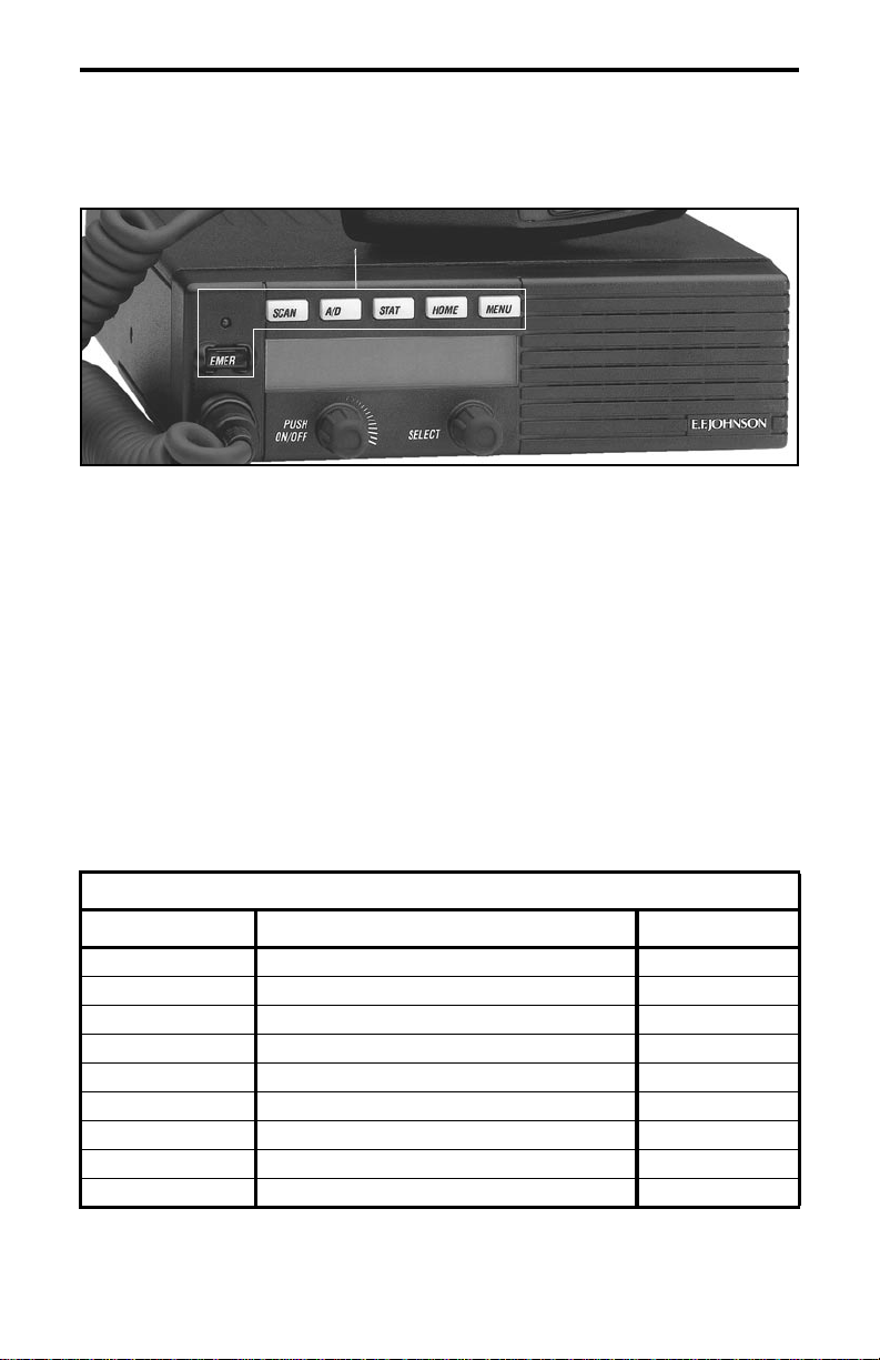
Option Switches
The six option switches with sample labels are shown above. Each
of these switches can control one function in the conventional mode and
another in the SMARTNET
The following tables indicate the functions available in each mode,
the key cap label normally u sed , and th e page i n thi s manual on wh ich th e
function is described. Since keys can control two different functions, the
key cap may not always indicate the correct function or a blank key cap
may be used. Consult your syst em operat or to deter mine if some swit ches
control two different functions. Refer to page 19 for more option switch
information.
®
/SmartZone™ mode.
CONVENTIONAL MODE
Key Cap Label Function See Page
BKLHT Backlight On-Off 17
C/S Clear/Secure 26
TG SEL T a lk Gr oup Select 37
DISP Displa yed Inf ormati on 33
EMER Emergency 33
- Hardware Key Select 26
TX PWR Transmit Power 32
HOME Home Zone 20
CALL Individual ID Call (or Private Call) 37
9

OPTION SWITCH FUNCTIONS
CONVENTIONAL MODE (Cont’d)
Key Cap Label Function See Page
PROG Keypad Programming 38
MON Monitor 29
SEL SQ Normal/Selective Squelch 30
PRI SEL Priority 34
RWS Radio Wide Scan 22
RTA Repeater Talk-Around 32
SEL SQ Selective (Call Guard) Squelch Select 30
SCAN Scanning On-Off 21
SCN ED Scan List Edit 25
TONES T ones On-Off 20
SMARTNET/SMARTZONE MODE
Key Cap Label Function See Page
BKLHT Backlight 17
ALERT Call Alert 50
RESP Call Response 48
C/S Clear/Secure 26
EMER Emergency 53
- Hardware Key Select 26
HOME Home Zone 20
MSG Message 52
PHONE Phone 48
CALL Priv ate Call (o r Individual ID Call) 45
RWS Radio Wide Scan 22
SCAN Scanning On-Off 54
SCN ED Scan List Edit 25
LOCK Site Lock 56
SEARCH Site Search 56
STATUS Status 52
TONES T ones On-Off 20
10

FEATURES
General Features
• Programmable for the following modes of operation:
– Conventional analog
– Conventional Project 25 (digital)
– SMARTNET™/SmartZone® trunked (analog or digital)
• Up to 16 zones with up to 16 channels each programmable
(256 channels total)
• Large liquid crystal display (LCD) with backlight.
• Six programmable option switches
• Standard and radio wide scan modes
• Time-out timer
• SecureNet
channels, DES-OFB on digital channels
Conventional Features
™
or 460 secure communication available on analog
FEATURES
• Up to 256 channels or talk groups programmable
• Repeater talk-around
• Monitor mode selected by microphone hanger or option switch
• Carrier or Call Guard
®
controlled squelch on analog channels
• Penalty and conversation timers
• Priority channel sampling when scanning
• Busy Channel Lockout (Transmit Disable On Busy)
• Individual ID calls on Project 25 channels
• User selectable high and low power output
• Emergency switch (P25 channels only)
• Keypad programming
SMARTNET™ II/SmartZone® Features
• Up to 256 talk groups programmable
• Group, Enhanced Private Conversation
and Telephone Calls
™
, Private Conversation II™,
• Emergency alarms to alert dispatcher of emergency conditions
• Emergency calling for high priority system access
11

FEATURES
• Failsoft operation on a predefined conventional channel if trunked
system fails
• Priority group calls detected while listening to other group calls
• Call Alert
™
(send and receive pages)
• Predefined messages (up to 16) can be sent to a dispatcher
• Predefined status conditions (up to 8) can be sent to a dispatcher
• Dynamic regrouping (dispatcher can automatically gather users on a
channel to receive a message)
• Roaming (SmartZone only)
• SecureNet
NOTE: The availability of many of the preceding features is
controlled by dealer programming of your transceiver, installed options,
and the capabilities of the radio system being accessed.
™
or 460 secure communication available
12
CONTROLS AND DISPLAY
CONTROLS AND DISPLAY
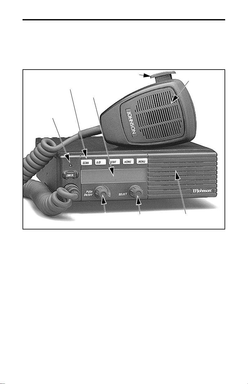
Six Option
Switches
Multi-function
Indicator
PTT Switch
Display
On-Off/
Volume
Figure 1 Front Panel Controls
Select
Switch
Microphone
Speaker
Front Panel Controls
On-Off/Volume - Pressing this control turns power on and off, and
rotating it sets the volume level.
Select Switch - Selec ts zones/ch annels and is also used for other f unctions
such as selecting names from a call list . When selecting zone s/channels, a
bar above the zone or channel display (see Figure 3) indicates which is
being changed. This bar is switched between displays by pressing this
switch, and zone or channel s are selected by rotati ng it (see “Zone/Channel
Select” on page 18).
13
CONTROLS AND DISPLAY
Multi-function Indicator - This is a two-color LED that ind icates the
following:
Red (constant) - Transmitter keyed (PTT switch pressed).
Green (constant) - Busy condition (carrier detected in receive mode).
Option Switches - Each of the six options switches on the front panel
(including the one l ocated to the left of the display) can be programmed by
your system operator to control some function. The switch functions can
be different for each operating mode (conventional and SMARTNET/
SmartZone). Therefore, up to 12 functions can be controlled by these
switches. Refer to p age 9 for more information on option switch fu nctions.
Speaker - An internal speaker is located behind the grille. An optional
external speaker may be used if desired. The internal speaker is disabled
when an external speaker is used.
PTT Swit ch - This push-button switch on the microphone is pressed to
talk (key the transmitte r) and release d to listen.
14
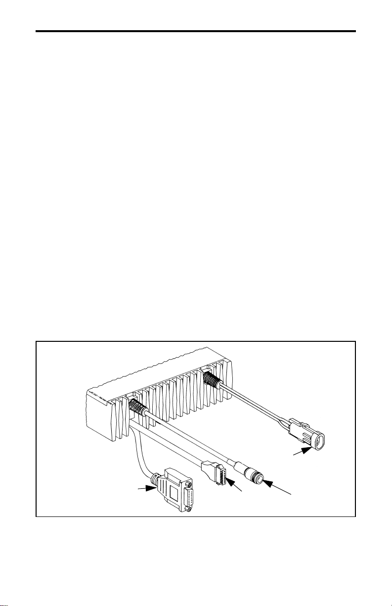
Optional
Remote Control
Unit Jack
Figure 2 Rear Panel Jacks
DC Power
Accessory
Jack
Jack
Antenna
Jack
CONTROLS AND DISPLAY
Rear Panel Jacks
DC Power Jack - Connection point for the nominal 12-volt, negative
ground power source (see Figure 2).
Antenna Jack - Type N jack for connecting the antenna.
Accessory Jack - Connection point for optional accessories such as an
external speaker (4-ohm, 12-watt) and ignition sense line.
Remote Control Unit Jack - Conne ction point for a r emote control u nit if
used. This cable is optional with front-mount models.
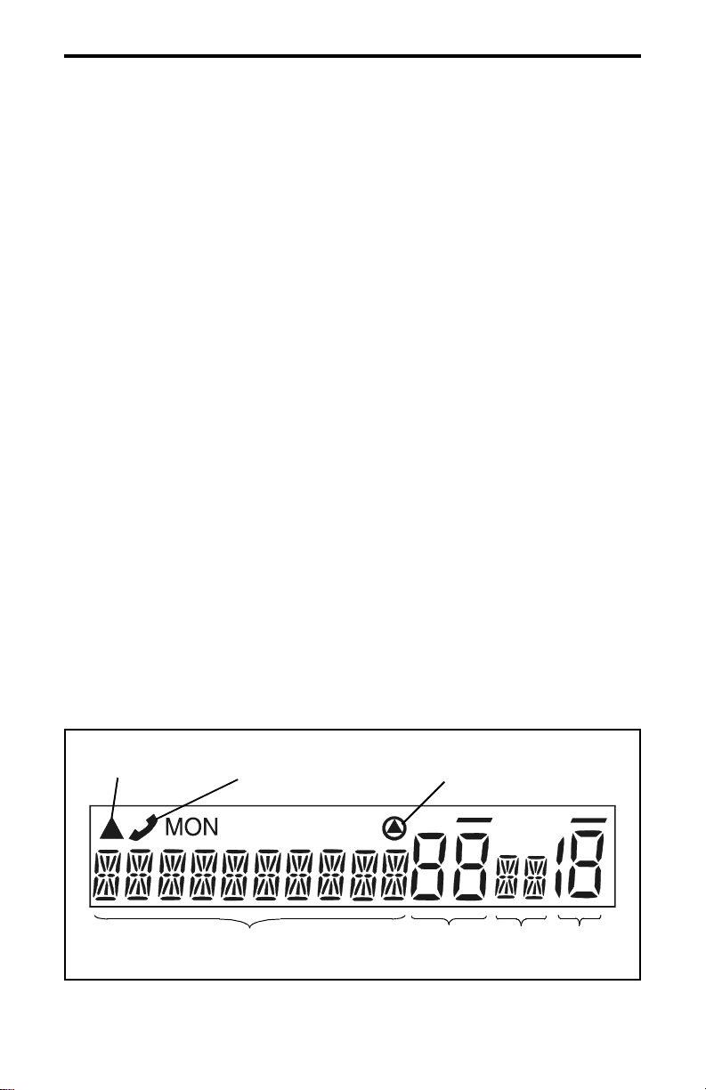
Display
Alphanumeric Display - This 10-character area of the display indicates
the alias (uniq ue identifica tion) for the selected ch annel. Depending on the
current mode, it may also indicate such things as the channel frequency,
system/group number, and status and error messages.
Zone Number - Indicates the currently selected zone from 1 up to 16. A
zone is a collection of channels that can be any combination of the
conventional and SMARTNET/SmartZone types.
Channel Number - Indicates the currently selected channel.
Scan Edit
Mode
10-Character Alphanumeric Display
Telephone/Special
Call Channel
Encryption
Zone
No.
Status
Display
Chnl
No.
Figure 3 Front Panel Display
15

CONTROLS AND DISPLAY
Stat us Displ ay - These two characters indicate the following status
information:
- This symbol in the left position indicates that the displayed
channel is in the scan list (scanned normally).
- A “P” in the left position indicates that the selected conventional
channel is a priority channel.
- This rotating cloc k-like symbol in t he right positi on indica tes that
scanning is enabled.
- Indicates that the displayed channel (or talk group) is programmed
for telephone calls.
- Indicates that voice encryption is enabled.
MON - Indicates that the monitoring is enabled by the Monitor option
switch (conventiona l operation only). This switch unsquel ches the receiver
so that all messages are heard on the channel. Refer to page 29 for more
information.
- The lines above the zone and channel displays indicate which
display is changed if the Select switch is turned. To switch between
displays, press the Select switch (see page 18).
- When this triangle is displayed, the scan list edit mode is indicated
(see page 25).
16

GENERAL OPERATION
GENERAL OPERATION
Turning Power On
When power is turned on by pressing the On-Off/Volume knob, the
multi-function indicator flashes green, a series of beeps sound, and an
initial greeting and operating mode are indicated by the alphanumeric
display. The zone and channel displays then indicate the currently
selected zone and channe l. Programming determi nes if the last select ed or
home zone is selected at power up.
Backlight Control and Display Viewing Angle Adjust
The backlight for the display and option keys can be manually
turned on and off if the
it is fixed in the on or off mode by programming.
If the display is d if fic ult t o read from t he angl e you nor mally view it,
the viewing angle can be adjusted. Simply press and hold the last option
switch above the display and then press the first option switch above the
display. Then release both switches and turn the Select switch until the
best contrast is obtained. This function times out in 3-5 seconds.
BKLHT option switch is pr ogra mmed. Other wise,
Setting Volume Level
The relative volume sett ing can b e det ermined by not ing t he posit ion
of the index on the On-Off/Volume knob. Otherwise, enable a reference
tone for use in setting the volume as follows:
• If the key press tones are enabled (see page 20), a short tone sounds
when an option switch is pressed or the Select switch is pressed or
rotated.
• If a conventional channe l is selected, take t he microphone off- hook and
if someone is talking, voice is heard. If the
switch is programme d (see page 29), pressing it unsquelches the trans ceiver and either voice or background noise i s heard. If a SMARTNET/
SmartZone channel is selected, the transceiver cannot be manually
unsquelched.
MON (Monitor) option
17

GENERAL OPERATION
Zone/Channel Display
The selected zone and channel are displayed by the zone and
channel displays shown in Figure 3 on page 15. In addition, a unique
alphanumeric ident ificatio n tag ( alias) is displa yed for e ach chan nel in th e
alphanumeric display area. This unique identification is programmed by
your system operator.
A zone can include any mix of channels. Up to 16 zones can be
programmed, and up to 16 channels can be programmed in each zone for
a total of up to 256 channels. Zones may be used for operation in
different geographical areas or radio systems. Consult your system operator for more inf or ma ti on on ho w to use the zones and channels that hav e
been programmed in your transceiver.
Zone/Channel Select
The front panel Select switch is used to change the zone and
channel. Pressing t his swi tch to ggles b etween t he zone and c hannel selec t
modes, and rotating it changes the zone or channel.
The current mode is indicated by the bar over the zone or channel
display. For example, when the bar is over the zone display (see
following illustration ), the zone select mode is enabled. Rotat i ng the
Select switch clockwise increases the zone or channel and rotating it
counterclockwise decreases the zone or channel number. After the
Channel Select Indicator
Zone Select Indicator
Zone
No.
18
Chnl
No.

GENERAL OPERATION
highest zone or channel is displayed, wrap-around to the lowest zone or
channel occurs and vice versa. If an unprogrammed channel is selected,
“UNPROGRAMD” is displayed and a tone sounds. The transceiver may
also be programmed so that only programmed channels are selected.
The transceiver can be programmed so that the bar defaults to either
the zone or channel d ispla y when power is turne d on and af ter a chan ge is
made. The delay that occurs before it returns is programmed for 1-15
seconds or infinite (“infinite” causes it to remain in the last selected
mode).
Setting Squelch Control
This transceiver does not have a squelch control. The squelch level
is preset and usually does not require readjustment. However, if the
squelch level needs to be changed on a conventional channel, it can be
changed using keypad programming if available (see page 43).
Option Switches
The six option switches on the front panel (one is located to the left
of the display) can be programmed by your system operator to control a
different set of functions for each of the two different operating modes
(see page 27). Refer to page 9 for more information on these switches.
Time-Out Timer
The time-out timer disables the transmitter if it is keyed for longer
than the programmed time. It can be programmed on each channel for
times from 15 seconds up to 3 minutes, 45 seconds or it can be disabled.
If the transmitter is keyed continuously for longer than the programmed
time, the transmitter is disabled, a continuous tone sounds, and
“TX TIMEOUT” is displayed. Five seconds before time-out occurs, a
warning beep sounds to indicate that time-out is approaching. The timer
and tone are reset by releasing the PTT switch.
One use of this feature is to prevent a channel from being kept busy
for an extended period by an accidentally keyed transmitter. It can also
19

GENERAL OPERATION
prevent possible transmitter damage caused by transmitting for an excessively long period.
Home Zone Select
If the HOME zone option switch is programmed, pressing it selects
the preprogrammed home zone. This provi des a quick way of retu rning to
the home zone. The transceiver may also be programmed so that whenever power is turned on, the home or last selected zone is automatically
selected.
Tone Select
The various alert tones that sound are described starting on page 56.
These tones can be enabled and disabled if the
TONE option switch is
programmed. To turn all tones off, press this switch and “TONE OFF” is
displayed. Then to turn all tones on again, press it and “TONE ON” is
displayed. If this switch is not programmed, tones are fixed in the on or
off condition by programming.
Power Turn-Off De lay
Your transceiver can be installed so that the vehicle ignition switch
as well as the front panel power switch control transceiver power. If this
is the case, both the ignition switch and the front panel power switch
must be on for transceiver power to turn on.
When the ignition switch controls power, a turn-off delay of up to
254 minutes can be programmed. The delay can be overridden at any
time by turning power off using the front panel power switch or turning
the ignition switch back on. A turn-off delay allows calls to be received
for a time after the ignition switch is turned off. At the same time, a dvantages of ignition swi tc h con tr ol are utilized such as preventing the b at ter y
discharge that may occur if the transceiver is left on for an extended
period (see page 59).
20