

Page 1
DIGITAL/ANALOG PORTABLE RADIO
OPERATING
MANUAL
5100 SERIES
PORTABLE RADIO
VHF/UHF/800 MHZ
PROJECT 25 CONVENTIONAL
SMARTNET™/SMARTZONE
®
7.2 VDC,
1 and 5 Watts (VHF);
1 and 4 Watts (UHF);
1 and 3 Watts (800 MHz)
Part No. 242-51xx-xxx
First Issue
May 2002
Supersedes: Part No.
Page 2

SAFETY TRAINING INFORMATION
SAFETY TRAINING INFORMATION
WARNING
This radio produces RF electromagnetic energy when
transmitting and is designed and classified for “Occupational Use Only”. Radio equipment with this classification must be used only during the course of employment
by individuals aware of the hazards and the ways to minimize such hazards. This radio is NOT intended for use by
the General Population in an uncontrolled environment.
This radio has been tested and complies with FCC
RF exposure limits for “Occupational Use Only”. In
addition, it complies with the following standards and
guidelines with regard to RF energy and electromagnetic
energy levels and evaluation of such levels for exposure
to humans:
• FCC OET Bulletin 65 Edition 97-01 Supplement C,
Evaluating Complian ce with FCC Guidelines for
Human Exposure to Radi o Frequency Electromagneti c
Fields.
• American National Standards Institute (C95.1-1992),
IEEE Standard for Safety Levels with Respect to
Human Exposure to Radi o Frequency Electromagneti c
Fields, 3 kHz to 300 GHz.
• American Nati onal S tandards Instit ute (C95.3 -1992),
IEEE Recommended Practice for the Measurement of
Potentially Hazardous Electromagnetic Fields - RF
and Microwave.
CAUTION
To ensure that your exposure to RF electromagnetic
energy is within the FCC allowable limits for occupational use, always adhere to the following guidelines:
• DO NOT use any accessories not specifically autho-
rized by the E.F. Johnson Company for use with this
radio such as batteries, speaker-microphones, belt
clips, and antennas. The use of unauthorized accessories can cause FCC RF exposure compliance requirements to be exceeded.
• ALW AYS keep the antenna and ra dio at l east 2 .54 cm
(1.0 inch) away from your body when transmitting to
ensure FCC RF exposure compliance requirements are
not exceeded. The best transmission quality results
when the antenna is at least 5 cm (2 inches) away from
your mouth and angled slightly to one side.
• This unit has not been tested for FCC RF exposure
compliance in applications where the unit is transmitting while body worn on the belt clip. This product is
not intended for use in applications where transmissions are required while the un it is body wo rn with the
use of the belt clip.
NOTE: The preceding information is provided to make
you aware of RF exposure and what to do to ensure that
this radio is operated within FCC RF exposure limits.
Electromagnetic Interference/Usage
Compatibility
This device complies with Part 15 of the FCC rules.
Operation is subject to the condition that this device does
not cause harmful interference. In addition, changes or
modification to this equipment not expressly approved
by the E.F. Johnson Company could void the user’s
authority to operate this equipment (FCC Rules, 47CFR
Part 15.19).
• DO NOT operat e the radio wi thout the p roper antenna
attached. This may damage the radio and cause FCC
RF exposure limits to be exceeded. The proper antenna
is the antenna supplied wi th th e r adi o by t he ma nufacturer or an antenna specifically authorized by the
manufacturer for use with this radio.
• DO NOT transmit more than 50% of total radio use
time (50% duty cycle ). Transmitting for more than
50% of the time can cause FCC RF exposure compliance requirements to be exceeded. This radio is transmitting whenever the i ndicator on the front panel is red
continuously. Pressing the PTT switch on the side
usually causes the radio to tra nsmit.
DO NOT operate it in areas that are sensitive to RF
energy such as aircraft, hospitals, blasting sites, and fuel
storage sites. Areas with potentially flammable atmospheres are usually, but not always, clearly posted. These
may include gas stations, fuel and chemical storage and
transfer stations, below deck on boats, and areas where
the air contains flammable chemicals or particles such as
grain dust or metal powders.
Dispose of the nickel metal-hydride (NiMH) or
nickel-cadmium (NiCd) battery used by this radio in
accordance with local regulatio ns. DO NOT dispose of i t
in fire because it can explode. Also, do not short the
terminals because it may become very hot.
May 2002
2
Part No. 002-5100-100
Page 3

51xx SERIES PORTABLE
OPERATING MANUAL
VHF/UHF/800 MHz
PROJECT 25 (DIGITAL) AND ANALOG
™
SMARTNET
Copyright© 2002 by the E.F. Johnson Company
The E.F. Johnson Company, which was founded in 1923, provides wireless communication
systems solutions for public safety, government, and commercial customers. The company
designs, manufactures, and markets conventional and trunked radio systems, mobile and
portable subscriber radios, repeaters, and Project 25 digital radio products. E.F. Johnson is a
wholly owned subsidiary of Transcrypt International, Inc.
/SmartZone
®
®
Viking Head/EFJohnson logo, Call Guard
the E.F. Johnson Company. SMARTNET
Enhanced Private Conversation
Inc. All other company and/or product names used in this manual are trademarks and/or registered trademarks of their respective manufacturer. The IMBE™ voice coding technology
embodied in this product is protected by intellectual property rights including patent rights of
Digital Voice Systems, Inc.
LAND MOBILE PRODUCT WARRANTY - The manufacturer’s warranty statement for this
product is available from your product supplier or from E.F. Johnson Company, 299 Johnson
Aven ue , Box 1249, Waseca, MN 56093-0514. Phone (507) 835-6222.
Information in this manual is subject to change without notice.
™
, and Private Conversation II™ are trademarks of Motorola,
, PCConfigure™, and PCTune™ are trademarks of
™
, SmartZone®, SecureNet™, Call Alert™,
Page 4

TABLE OF CONTENTS
TABLE OF CONTENTS
SAFETY TRAINING INFORMATION. . . . . . . . . . .2
FEATURES. . . . . . . . . . . . . . . . . . . . . . . . . . . . . . . . . . .5
General Features . . . . . . . . . . . . . . . . . . . . . . . . . . . . . .5
Conventional Features. . . . . . . . . . . . . . . . . . . . . . . . . .5
SMARTNET/SmartZone Features . . . . . . . . . . . . . . . .5
CONTROLS AND DISPLAY. . . . . . . . . . . . . . . . . . .6
Front Panel Controls . . . . . . . . . . . . . . . . . . . . . . . . . . .6
Top Panel Controls . . . . . . . . . . . . . . . . . . . . . . . . . . . .7
Side Controls. . . . . . . . . . . . . . . . . . . . . . . . . . . . . . . . .7
Display. . . . . . . . . . . . . . . . . . . . . . . . . . . . . . . . . . . . . .8
GENERAL OPERATION . . . . . . . . . . . . . . . . . . . . . .8
Turning Power On. . . . . . . . . . . . . . . . . . . . . . . . . . . . .8
Setting Volume . . . . . . . . . . . . . . . . . . . . . . . . . . . . . . .8
Power-Up Password . . . . . . . . . . . . . . . . . . . . . . . . . . .9
Zone And Channel Select . . . . . . . . . . . . . . . . . . . . . . .9
Low Battery Indication . . . . . . . . . . . . . . . . . . . . . . . . .9
Backlight . . . . . . . . . . . . . . . . . . . . . . . . . . . . . . . . . . . .9
Keypad Lock . . . . . . . . . . . . . . . . . . . . . . . . . . . . . . . . .9
Setting Squelch . . . . . . . . . . . . . . . . . . . . . . . . . . . . . .10
Transceiver Operating Modes. . . . . . . . . . . . . . . . . . .10
Conventional Operating Mode . . . . . . . . . . . . . . . 10
SMARTNET/SmartZone Operating Mode. . . . . . 10
Secure Communication . . . . . . . . . . . . . . . . . . . . . . .10
Encryption (Hardware) Keys . . . . . . . . . . . . . . . . 11
RADIO-WIDE FEATURES. . . . . . . . . . . . . . . . . . . .11
Option Keys. . . . . . . . . . . . . . . . . . . . . . . . . . . . . . . . .11
Menu Mode . . . . . . . . . . . . . . . . . . . . . . . . . . . . . . . . .11
Time-Out Timer. . . . . . . . . . . . . . . . . . . . . . . . . . . . . .12
Home Zone Select . . . . . . . . . . . . . . . . . . . . . . . . . . . .13
Power Output Select . . . . . . . . . . . . . . . . . . . . . . . . . .13
Alert Tone Select. . . . . . . . . . . . . . . . . . . . . . . . . . . . .13
Scanning . . . . . . . . . . . . . . . . . . . . . . . . . . . . . . . . . . .13
Standard Scanning. . . . . . . . . . . . . . . . . . . . . . . . . 13
Radio Wide Scanning . . . . . . . . . . . . . . . . . . . . . . 13
Scan Resume Delay. . . . . . . . . . . . . . . . . . . . . . . . 14
Transmitting in the Scan Mode. . . . . . . . . . . . . . . 14
Nuisance Channel Add/Delete . . . . . . . . . . . . . . . 14
Scan Lists. . . . . . . . . . . . . . . . . . . . . . . . . . . . . . . . . . .14
Radio Wide Scan List . . . . . . . . . . . . . . . . . . . . . . 14
Standard Mode Scan Lists. . . . . . . . . . . . . . . . . . . 14
Determining Which Channels are in Scan List. . . 14
Selecting a Scan List. . . . . . . . . . . . . . . . . . . . . . . 15
Programming a Scan List . . . . . . . . . . . . . . . . . . . 15
CONVENTIONAL MODE FEATURES . . . . . . . .16
Monitoring Before Transmitting . . . . . . . . . . . . . . . . .16
Automatic Channel Monitoring . . . . . . . . . . . . . . 16
Manual Channel Monitoring. . . . . . . . . . . . . . . . . 16
Monitor Mode . . . . . . . . . . . . . . . . . . . . . . . . . . . . . . .16
Busy Channel Lockout . . . . . . . . . . . . . . . . . . . . . . . .16
Call Guard Squelch . . . . . . . . . . . . . . . . . . . . . . . . . . .17
Call Guard Squelch Enable/Disable. . . . . . . . . . . . 17
Selective Squelch Code Select. . . . . . . . . . . . . . . . 17
Penalty Timer. . . . . . . . . . . . . . . . . . . . . . . . . . . . . . . 17
Conversation Timer . . . . . . . . . . . . . . . . . . . . . . . . . . 18
Repeater Talk-Around . . . . . . . . . . . . . . . . . . . . . . . . 18
Displaying Transmit and Receive Frequency . . . . . . 18
Emergency Mode . . . . . . . . . . . . . . . . . . . . . . . . . . . . 18
Conventional Mode Scanning . . . . . . . . . . . . . . . . . . 18
Priority Channel Sampling. . . . . . . . . . . . . . . . . . . . . 18
Changing the Priority Channel. . . . . . . . . . . . . . . . 19
Placing and Receiving Conventional Calls . . . . . . . . 19
Project 25 (Digital) Mode Features . . . . . . . . . . . . . . 19
Viewing Individual ID. . . . . . . . . . . . . . . . . . . . . . 19
Group IDs. . . . . . . . . . . . . . . . . . . . . . . . . . . . . . . . 19
Selective Squelch. . . . . . . . . . . . . . . . . . . . . . . . . . 19
Changing Talk Group As signed To A Channel. . . 19
Unit Calls . . . . . . . . . . . . . . . . . . . . . . . . . . . . . . . . 20
Keypad Programming. . . . . . . . . . . . . . . . . . . . . . . . . 20
Menu Structure. . . . . . . . . . . . . . . . . . . . . . . . . . . . 20
Zone Password. . . . . . . . . . . . . . . . . . . . . . . . . . . . 21
Zone Change Parameter. . . . . . . . . . . . . . . . . . . . . 21
Channel Change Parameter . . . . . . . . . . . . . . . . . . 21
System Parameters. . . . . . . . . . . . . . . . . . . . . . . . . 21
Channel Parameters . . . . . . . . . . . . . . . . . . . . . . . . 22
SMARTNET/SMARTZONE FEATURES . . . . . . 23
Viewing Unit ID. . . . . . . . . . . . . . . . . . . . . . . . . . . . . 23
Placing and Receiving Standard Group Calls . . . . . . 23
Private (Unit-To-Unit) Calls . . . . . . . . . . . . . . . . . . . 24
General. . . . . . . . . . . . . . . . . . . . . . . . . . . . . . . . . . 24
Placing an Enhanced Private Conversation Call . . 24
Placing a Private Conversation II Call. . . . . . . . . . 25
Receiving a Private Call (All Types). . . . . . . . . . . 25
Placing and Receiving Telephone Calls. . . . . . . . . . . 26
Call Alert . . . . . . . . . . . . . . . . . . . . . . . . . . . . . . . . . . 27
Answering a Page. . . . . . . . . . . . . . . . . . . . . . . . . . 27
Initiating a Page . . . . . . . . . . . . . . . . . . . . . . . . . . . 27
Messaging. . . . . . . . . . . . . . . . . . . . . . . . . . . . . . . . . . 28
Sending Status Conditions . . . . . . . . . . . . . . . . . . . . . 28
Emergency Alarm and Call . . . . . . . . . . . . . . . . . . . . 28
Failsoft Operation. . . . . . . . . . . . . . . . . . . . . . . . . . . . 29
SMARTNET/SmartZone Scanning . . . . . . . . . . . . . . 29
Dynamic Regrouping . . . . . . . . . . . . . . . . . . . . . . . . . 29
SmartZone Features . . . . . . . . . . . . . . . . . . . . . . . . . . 30
Busy Override . . . . . . . . . . . . . . . . . . . . . . . . . . . . 30
Determining Current Site/Searching For New Site 30
Locking/Unlocking a Site . . . . . . . . . . . . . . . . . . . 30
SUPERVISORY TONES . . . . . . . . . . . . . . . . . . . . 30
INDEX . . . . . . . . . . . . . . . . . . . . . . . . . . . . . . . . . . . . . . 32
May 2002
4
Part No. 002-5100-100
Page 5

FEATURES
FEATURES
General Features
• The following operating modes are programmable:
– Conventional analog
– Conventional Project 25 (digital)
– SMARTNET
™
/SmartZone® trunked
• Up to 500 channels/talk groups programmable
• Zone select
• Large graphic display with backlight
• Up to 9 (limited keypad) or 21 (DTMF keypad)
programmable option keys
• Menu mode
• Standard and radio-wide scan modes
• User selectable and editable s can lists
• Time-out timer
• User selectable high and low power output
• Keypad loc k
• Power-up password to prevent unauthorized use
Conventional Features
• Repeater talk-around
• Monitor mode selectable by option key or menu
• Carrier or Call Guard
squelch on analog channels. Carrier, NAC and talk
group IDs on digital channels.
®
(CTCSS/DCS) controlled
• Penalty and conversation timers
• Priority channel sampling when scanning
• Busy channel lockout (transmit disable on busy)
• DES-OFB encryption available (P25 channels)
• Unit (Individual I D) calls on Pr oject 25 channels
• Keypad programming (Fed Gov. users only)
• Emergency key (Project 25 channels)
SMARTNET/SmartZone Features
• Group, Enhanced Private Conversation™, Private
Conversation II™, and Telephone Calls
• Emergency alarms to alert a dispatcher of
emergency conditions
• Emergency calls for high priority system access
• Failsoft operation on a predefined conventional
channel if trunked system fails
• Prio rity group calls d etected whi le listeni ng to o ther
group calls
• Call Alert™ (send and receive pages)
• Predefined messages (up to 16) can be sent to a
dispatcher
• Prede fined status condit ions (up to 8) can be sent to
a dispatcher
• Dynamic regrouping (dispatcher can automatically
gather users on a channel to receive a message)
• Roaming (SmartZo ne only)
• SecureNet™ secure communication available
NOTE: The availability of many of the preceding features is determined by system operator programming
of your transceiver, installed options, and the capabilities of the radio system being accessed.
May 2002
5
Part No. 002-5100-100
Page 6
CONTROLS AND DISPLAY
Display
CONTROLS AND DISPLAY
In Various Modes:
F1 = Exit
F2 = Select/Menu
Enable
DTMF Keypad Model
Up/Down Sw
Menu/Option
Option Keys
DTMF Keypad
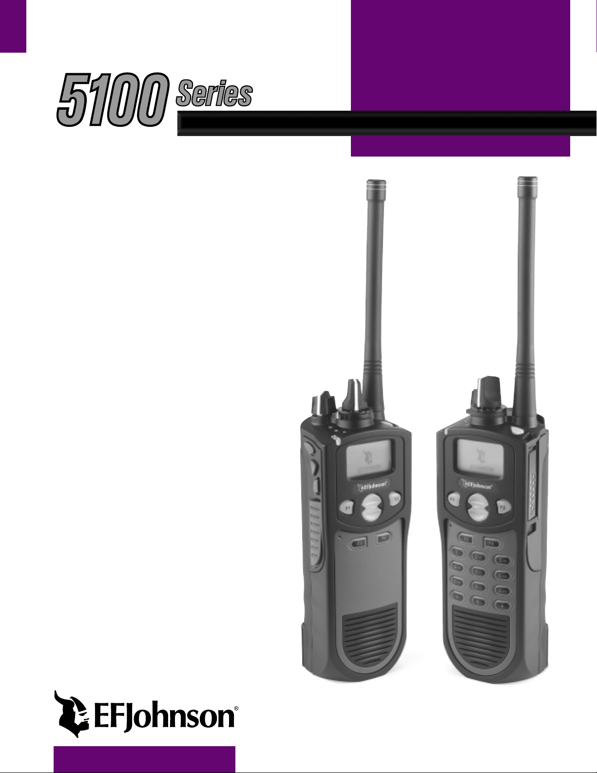
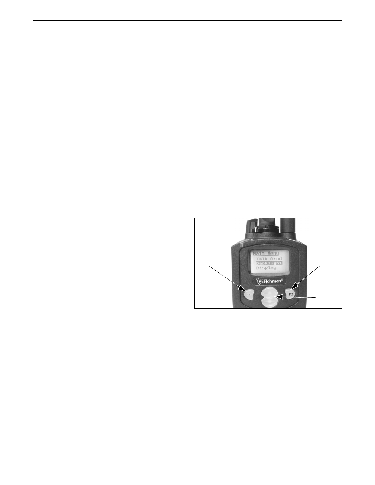
Figure 1 Front Panel Controls
Front Panel Controls
NOTE: The following controls are shown in Figure 1.
Keys
Microphone
Speaker
Limited Keypad Model
F1 - In menu mode, functions as a step back and exit
key. If menu mode is not used, it is a programmable
option key.
Microphone - The microphone is located in this area.
For best results, hold the transceiver 2-3 inches from
you mouth and speak at a normal conversational level.
Display - This is a graphical LCD (Liquid Crystal
Display). The display backlight can be progr ammed to
turn on when any key is press ed or whe n the Bac kligh t
option key is pressed (see page 9).
Up/Down Switch - Selects zones when multiple zones
are programmed. Pressing the upper part of the switch
selects the next higher number and pressing the lower
part selects the next lower number. This control also
provides up/down select in the menu mode and in
other modes when up/down select is required.
F2 - Selects the menu mode when that mode is
enabled by programming. Also functions as an Enter
or Select key in the menu and other modes. If menu
mode is not used, it is a programmable option key.
F3, F4 - Programmable option keys.
DTMF Keypad - The full keypad DTMF models
include the 12 keys required to dial tel epho ne and unit
ID numbers.
Speaker - The transceive r speaker is lo cated near the
bottom of the front panel. When a speake r/micropho ne
is used, this speaker is a utomaticall y disabled.
May 2002
6
Part No. 002-5100-100
Page 7
CONTROLS AND DISPLAY
Emergency
(Option)
Power On-Off/
Volume Adj
Channel
Switch
Antenna
Connector
Option
Switch
Key
Multi-Function
Indicator
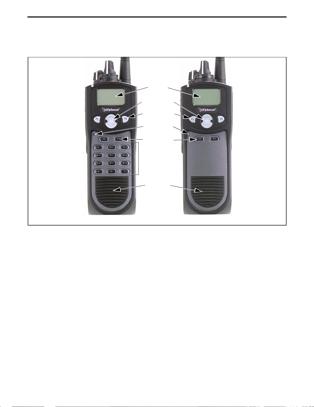
Top Panel Controls
Figure 2 Top Panel Controls
Multi-Function Indicator - Indicates the following
conditions:
Emergency Key - This key or some other option key
can be programmed as an Emergency key to alert a
dispatcher of an emergency condition. Refer to pages
18 and 28 for more information. This key can also be
programmed for other functions.
Side Controls
Option Keys
1
2
3
PTT Switch
Accessory
Connector
Steady Red
Flashing Red
Steady Green
On-Off/Volume - Turning the knob clockwise turns
power on and sets the volume level. Turning it counterclockwise to the detent turns power off. The
minimum volume level can be set by programming.
Channel Switch - This 16-position switch selects up
to 16 channels in the current zone. Additional zones
can be programmed to allow up to 500 channels to be
selected by this switch.
Rotary Option Switch - This is a three-position
switch that can be programmed to control various
options. The “A” an d “B” posi tions ar e “of f” and “on”,
respectively, and the “C” position is not used (see
page 11).
Antenna Connector - Connection point for the
antenna. Make sure the antenna is tight before using
the radio.
- Transmitter keyed.
- Low battery in receive mode.
- Carrier detected in receive mode.
Battery Pack
Figure 3 Side Controls and Jacks
PTT (Push-To-Talk) Switch - This switch is pressed
to turn the transmitter to transmit a message. It is then
released to listen. Transmitting is indicated when the
top panel indicator is constant red.
Option Keys 1, 2, and 3 - Each of these keys can be
system operator programmed to control a specific
function (see page 11).
Battery - To remove the battery, press the releas e
button on the bottom and rotate the bottom of the
battery outward.
Accessory Connector - Connection point for optional
accessories such as a spe aker/micropho ne or earphone.
May 2002
7
Part No. 002-5100-100
Page 8
GENERAL OPERATION
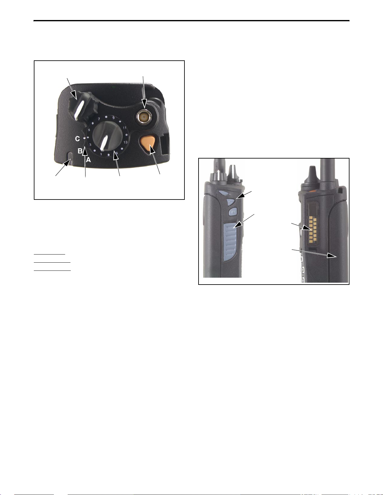
Icon
Area
Text
Area
Display
Figure 4 Graphical Display
The front panel display is shown above. Icons are
typically shown in the upper part of the display and
text messages in the lower part. The default icons are
as follows:
- When the scan or the scan list edit mode is
enabled, indicates that the displayed channel is in the
scan list and scanned normally (see page 14).
- When the scan or the scan list edit mode is
enabled, indicates that the displayed channel is a
priority channel.
- Low battery indication (see page 9).
- Voice encryption is enabled (see page 10).
- Standard or radio wide scanning is enabled
(see page 13).
- Repeater talk-around is enabled (see page 18).
- Monitor mode is enabled by the Monitor
option key or menu parameter (see page 16).
- Keypad programming or another mode is
enabled which allows the user to edit radio parameters.
- A SMARTNET/SmartZone interconnect (tele-
phone) call is in progress (see page 26).
- A Project 25 or SMARTNET/SmartZone
private (unit-to-unit) call is in progress.
GENERAL OPERATION
Turning Power On
Power is turned on and off by the top panel OnOff/Volume switch. When power is initia ll y tur ned on,
the transceiver goes through a self test routine in
which the following information is displayed:
• Currently selected zone
• Individual ID of the radio if a conventional P25
channel is selected
• Unit ID of the radio if a SMARTNET/SmartZone
channel is selected
• Selected channel alias (last)
Programming determines if the transc eiver
powers up on the last selected zone or the preprogrammed home zone. The last selected channel of
the displayed zone is always selected on power up.
Setting Volume
The relative volume level can be determined by
the position of the index on the volume knob or a
reference tone as follows. The minimum volume level
may be set by programming. This can prevent missed
messages resulting fro m inadvertently turning the
volume to an inaudible level.
• If a key press tone is enabled, a short tone sounds
when a key is pressed.
• If a conventional channel is selected and the
Monitor option key or menu parameter is
programmed, pressing that key unsquelches the
receiver and either voice or background noise is
heard (see page 16). If a SMARTNET/SmartZone
channel is sele cted, the r eceiver ca nnot be manually
unsquelched.
May 2002
8
Part No. 002-5100-100
Page 9

GENERAL OPERATION
Power-Up Password
The power-up password feature prevents unauthorized use of the transceiver by locking the keypad
on power up until t he pr oper pa ssword is entered. This
feature is enabled or disabled by programming.
When it is enabled, “ENTER PSWD” is briefly
displayed when power is turned on. The eight-digit
numeric password must be then be entered as follows.
If an incorrect password is entered, “INCORRECT” is
displayed and it must be re-entered.
DTMF Keypad Models - Enter the password using
the 0-9 keys and then press the Enter (F2) key when
finished. If a mistake is made, the last digit can be
erased by pressing the F1 (Clear) key.
Limited Keypad Models - Select the proper number
for each position by pressing the Up/Down switch.
When the proper number for a position is displayed,
select it and move on to the next position by pressing
the F2 (Enter) key.
Zone And Channel Select
Zone Select
The front panel Up/Down switch changes and
displays the current zone. When not in special modes
such as the menu mode, pressing either the top or
bottom part of this switch once displays the current
zone number as “Zone x”. Then quickly pressing it
again changes the selected zone up or down.
After the highest programmed zone is displayed,
wrap-around to the lowest programmed zone occurs
and vice versa. The selected zone is also displayed
briefly on power up.
Channel Select
Channels are selected by the rotary 16-position
switch on the top panel. The alias (identification) for
the selected channel/group is displayed continuously
during normal operation.
When an unprogrammed channel is selected,
“UNPROGRAMD” is displayed and a tone sounds (if
tones are enabled). When conventional channels are
selected and the Display Information option key or
menu parameter is programmed, either the channel
frequency or alias can be displayed (see page 18).
Low Battery Indication
NOTE: If the transceiver contains hardware (encryption) keys, be sure to reattach a battery wit h i n app roximately one minute to prevent the loss of these keys.
A low-battery condition is indicated by the
icon in the display. The battery should be recharged or
replaced as soon as practical after this indication
appears. Once this indication appears, it stays on until
power is cycled.
The following additional
and conditions may be enabled by programming:
low battery indications
• A chirp sounds once a minute in the standby and
transmit modes.
• A chirp sounds each time the PTT switch is pressed.
• Top panel LED indicator flashes red every 30
seconds in the receive mode.
• Low power is selected when transmitting.
As indicated in the preceding “Note”, the transceiver must be connected to a constant power sourc e
to preserve the hardware ( encrypti on) keys in memory.
Since thes e keys are ma intained in m emory for only
about 1 minute without a battery attached, be sure to
reattach a battery within that time if th ese keys are
used. Refer to see page 10 for more information on
encryption keys.
Backlight
The backlight for the disp la y and opt ion keys can
be programmed to au tomati call y tur n on whe n any key
is pressed. It then automatically turns off after a
programmed delay of 0-7.5 seconds so that battery
drain is minimized. If the Backlight option key or
menu parameter is programmed, it can be used to
manually turn the backlight on and off.
Keypad Lock
The Keypad Lock feature is used to temporarily
disable the front panel keys to prevent accidental key
presses. This feature is available if the Keypad Lock
option key is programmed.
May 2002
9
Part No. 002-5100-100
Page 10

GENERAL OPERATION
To lock the keypad, simply press the Keypad
Lock option key. Then to unlock the keypad again,
press and hold this key until a tone sounds (approximately 1 second).
With DTMF keypad models, the DTMF keys can
also be totally disabled by programming on some or
all channels. The Keypad Lock feature then has no
affect on those keys.
Setting Squelch
This transceiver does not have a squelch control.
The squelch level is fixed and normally does not
require readjustment.
Transceiver Operating Modes
Introduction
Each selectable channel can be programmed for
either conventional or SMARTNET/SmartZone operation. For example, Zone 1/Channel 1 could be a
conventional channel, Zone 1/Channel 2 a
SMARTNET channel, and so on. Your system operator can tell you what type or types of operation are
programmed. Mode information on these modes
follows.
Conventi onal Operating Mode
This is a non-trunked operating protocol which
accesses independent radio channels. There is no automatic access to several c hannels. Monitoring of the
channel before transmitting may not be automatic in
this mode, so you may have to do it manually to make
sure that it is not in use. Either analog or digital
(Project 25) s ig nal ing may be used. Operatin g f ea tur es
unique to this mode are described starting on page 16.
SMARTNET/SmartZone Operating Mode
This is a trunked operating protocol that provides
automatic access to several channels. A “channel”
actually selects a talk group which is programmed
with one or more ID codes that determine what
mobiles are being called and what calls are received.
Monitoring is performed automatically, and special
tones and messages indicate busy and out-of-range
conditions. Enhanced features include roaming
(SmartZone only), telephone, private, and emergency
calls, Call Alert™, and messagi ng. Either analog or
digital signaling may be used. Operating features
unique to SMARTNET/SmartZone operation are
described starting on page 23.
When a SMARTNET or SmartZone channel is
selected or the radio is powered up on one of those
channels, it searches for a control channel. Once a
control channel is found, it attempts to register on the
radio system and the alias (name) of the selected
channel is displayed. If a control channel could not be
found (because of an out of range condition or the
system ID is not correct, for example ), “NO SYS” or a
similar message is di splayed an d the radi o continue s to
search for a control channel.
The control channel transmits and receives
system information to and from all radios register ed on
the system. Therefore, once a contro l channel i s found,
it is contin uously monitored for inco ming call in formation and is used to make call requests. The radio
automatically chang es t o a tra ffic channel to plac e and
receive cal l s and then re turns to the co ntrol channel
when the call is complete.
Secure Communication
General
This transceiver may be optionally e quipped to
provide secure communication on some or all channels. This feature encrypts your voice so that it can be
understood only by someone using a transceiver
equipped with a similar encryption device and encryption codes .
When a secure call is recei ved or transmitted,
is indicated in the di spl ay. Secure communication
can be programmed on a per channel basis to operate
in various ways. If the current channel is programmed
to allow it to be selected, secure communication can
be manually enabled and disabled by the Clear/Secure
option key or menu parameter. In the receive mode,
secure calls may be auto detected or only calls coded
like the transmit signal may be received.
If the “Clear” mode is selected by Clear/Secure
key or menu parameter and an attempt is made to
10
May 2002
Part No. 002-5100-100
Page 11
RADIO-WIDE FEATURES
transmit on a channel fixed in the “Secure” mode by
programming, “SEC ONLY” is displayed and transmitting is not permitted. Conversely, if the “Secure”
mode is selected and the channel is fixed in the
“Clear” mode, “CLEAR ONLY” is displayed and
transmitting is not permitted.
If your transceiver has encryption, consult your
system oper ator for more information o n how it functions in your application.
Encryption (Hardware) Keys
NOTE: A nearly constant power source must be
applied to the radio to main tain the encryp tion keys in
memory . Ther efor e, when changing the battery , be su re
to reattach another battery within one minute. If it is
not, these keys may be lost and will need to be
reloaded again.
RADIO-WIDE FEATURES
Option Keys
Each channel programmed for encryption has an
encryption key associated with it. Up to 16 keys can
be loaded into the radio, and the location from 0-15
refers to the “Hardware” location of the key. If more
than one key is loaded, the Hardware Key Select
option key may be programmed to select another key
for a channel. A new key selection remains in affect
until it is manually changed again. Select a hardware
key as follows:
1. Press the Hardware Key Select key o r select that
menu parameter and HWKEY x is displ ayed (“x” is
the current key selection from 0-15).
2. Press the Up/Do wn switch to display t he desired key
and then press t he Hardware Key Select key again or
F2 key to select it and return to normal operation.
Almost all the transceiver keys are programmable
unless they are dedicated to a specific function. These
keys can be programmed by your system operator for
one set of functions in the Conventional mode and
another in the SMARTNET/SmartZone mode as
described on page 10. Table 5 on page 12 lists the
programmable keys, the functions that can be
programmed in each mode, and the page of this
manual on which the function is described.
Menu Mode
Most functions that can be controlled by an
option key can also be controlled by the menu mode.
An exception is Keypad Lock which can be cont ro lled
by an option key only. The functions that can be
controlled by the menu mode are also shown in Table
5 on page 12. Only parameters that apply to the
selected channel type (Conventional/SMARTNET/
SmartZone) are displayed.
When the menu mode is used, the F1 and F2 k eys
become dedicated menu mode control keys: F1 is
Back/Clear, and F2 is Menu Select/Enter. If the menu
mode is disabled, these keys can be programmed for
other functions. The menu mode operates as follows:
Menu
Back/
Exit
Menu
Select/
Enter
Menu
Scroll
Up/Down
1. To select the menu mode, press the F2 key. Up to
three menu para meters are t hen displ ayed as sho wn
in the preceding illustration.
2. To scroll up or down through the menu parameter
list, press the Up/Down switch. The selected
parameter is indicated by a dark bar.
3. To display the available modes for a highlighted
parameter, press the F2 key. The currently selected
mode is indicated by an asterisk.
NOTE: Some parameters cannot be selected with
scanning enabled.
11
May 2002
Part No. 002-5100-100
Page 12

RADIO-WIDE FEATURES
4. Press the Up/Down switch to highlight the desired
mode. Then select the F2 key to select that mode.
If the transmitter is keye d for longer than the
programmed time, the transmitter is dis abl ed, a cont in uous tone sounds, and “TX TIMEOUT” is displayed.
5. To step back to the previous level or exit the menu
mode, press the F1 (Clear) key.
Five seconds before time-out occurs, a warning beep
sounds to indicate that time-out is approaching. The
timer and tone are reset by releasing the PTT switch. A
Time-Out Timer
The time-out timer disables the transmitter if it is
keyed continuously for longer than the programmed
time. It can be programmed for t imes fro m 15 seco nds
up to 3 minutes, 45 seconds or it can be disabled.
different time may be programmed on each channel.
Conventional channels can also be programmed
with a pena lty timer wh ich prevents transmissions for
a time after the transmitter is disabled by the time-out
timer. Refer to page 17 for more information.
Table 5 Programmable Option Key and Menu Mode Functions
Function
Alert tones On-Off T ones X X X 13
Backlight On-Off Backlight X X X 9
Call Alert Select X X 27
Call Response Select X X 24
Clear/Secure Select Security X X X 10
(Digital) Talk Group Select Select TG X 19
Display Information Select Display X 18
Emergency Select Emergency X X X 18, 28
High/Low Power Select Tx Power X X X 13
Home Zone Select Home Zone X X X 13
Key (Encr yption) Sel ect X X X 10
Keypad Lock Select (Opt sw only) X X X 9
Keypad Programming Select Keypad Prg X 20
Messaging X X 28
Monitor Mode Select Monitor X 16
Normal/Selective Select Squelch X 17
Phone Call Select X X 26
Priority Channel Select Priority X 18
Private Call Select X X 24
Radio Wide Scan Select X X X 13
Repeater Talk-Around Select Talk Arnd X 18
Scan Mode Select Scan X X X 13
Scan List Edit Select Scan Edit X X X 13
Scan List Select Scan Selct X X X 13
Selective Squelch Code Select Sqlch Code X 17
Site Lock Select X 30
Site Search Select X 30
Status Select X X 28
Unit Call Select Unit Call X 19
Unprogrammed (not used) - X X X -
Menu
Display
Conv. SMARTNET SmartZone
Available in Mode:
See Description
on Page:
12
May 2002
Part No. 002-5100-100
Page 13

RADIO-WIDE FEATURES
Home Zone Select
If the Home Zone option key or menu paramet er is
programmed, it can be used to quickly select the
preprogrammed home zone. The transceiver is also
programmed so that when power is turned on, the
home or last selected zone is automatically selected.
Power Outpu t Select
If selectable power is allowed on the channel by
programming, the High/Low Power option key or
menu parameter can be used to select high or low
power. Low power increases battery life but may
decrease range and vice versa for high power.
The new level is flashed in the display as either
“HI POWER” or “LOW POWER”. If selectable
power is not permitted on the current channel,
“FIXED LOW” or “FIXED HIGH” is flashed and no
power change occurs. The selected power level on the
channel is permanent until it is manually changed
again.
Alert Tone Select
The various alert tones that sound are described
on page 30. These tones can be tu rne d on and off if the
Alert Tone option key or Tones menu parameter is
programmed. When all tones are off, “TONE OFF” is
momentarily displayed, and when all tones are on,
“TONE ON” is momentarily displayed. If this key or
menu parameter is not programmed, tones are fixed in
the on or off mode by programming.
Scanning
Introduction
Scanning monitors the channels in the scan list
for messages that the transceiver is programmed to
receive. When a message is detected, scanning stops
and the message is received. Shortly after the message
is complete, scanning resumes (unless it has been
disabled).
There are tw o basic scan modes ava ilable: Standard and Radio Wide. The operation of the standard
type is unique to the type of channel selected, and the
operation of Radio Wide type is the same regardless of
the type of channel selected. Only one type can be
enabled at a time. For example, if standard scanning is
enabled and radio wide scanning is selected, standard
scanning i s automatically disabled. More infor mation
on these types of scanning follows.
Standard Scanning
Standard scanning monitors only channels that
are the same type as that currently selected. For
example, if a conventional channel is selected, only
conventional channels are scanned. Standard scanning
operates as follows:
• Enable s cannin g using t he Scan op tion key or menu
parameter. Scanning is enabled when the icon
is displayed.
• To turn scanning off, press the Scan option key
again or select “Off” in the scan menu. Scanning is
disabled when the icon is no longer displaye d.
• If the zone or channel is changed while scanning is
selected, scanning continues on the same or a
different scan list (see “Standar d Mode Scan Lists”
on page 14).
Radio Wide Scanning
Radio wide scanning mon itors the ch annels in the
radio-wide scan list. This scan list can include up to 16
channels of any type and assigned to any zone (see
“Radio Wide Scan List” on page 14). Radio wide
scanning is turned on and off by the Radio Wide Scan
option key or menu paramete r as fol lows. If thi s key or
menu parameter is not programmed, radio wide scanning is not available.
• Enable Rad io W id e Scanning using the Radio W ide
Scan option key or menu parameter. As with standard scanning, radio wide scanning is indicated
when the icon is displayed.
• To turn radio wide scanning off, press the Radio
Wide Scan option key again or select “Off” in the
menu. Scanning is disable d when the icon is no
longer displayed.
• If the zone or channel is changed while radio wide
scanning, scanning continues normally.
13
May 2002
Part No. 002-5100-100
Page 14

RADIO-WIDE FEATURES
Scan Resume Delay
When a message is received or transmitted while
scanning, there is a delay before scanning resumes.
The delay after receiving a call prevents another
message from being received before a response can be
made. The delay after tr ansmit ting a ca ll ensu res that a
response is heard ins tead of another mess age occurring
on some other channel.
Transmitting in the Scan Mode
When the transmitter is keyed while scanning is
enabled, the transmission may occur on the receive,
selected, or priority channel, depending on the operating mode and programming.
Nuisance Channel Add/Delete
With standard scanning, both conventional and
SMARTNET/SmartZone channels can be temporarily
deleted from the scan list, for example, if messages
become annoying. This feature is not available with
radio wide scanning. Channels can also be permanently added or delet ed fro m a scan l ist a s descr ibed i n
the next section. Proceed as follows to temporarily
delete a nuisance channel:
Scan Lists
Radio Wide Scan List
With radio wide scanning, there is only one scan
list available regardless of the type of cha nnel selecte d,
and it is not user programmable. This scan list can
contain up to 16 channels of any type. For example, it
could include six conventional channels and ten
SMARTNET/SmartZone channels.
Standard Mode Scan Lists
NOTE: The selected channel is always scanned.
A scan list is simply the channels that are scanned
when scanning is selected. With conventional and
SMARTNET/SmartZone operation, several scan lists
can be programmed by your system ope rator, and each
list can include up to 16 channels/talk groups.
The channels/groups in a list are user programmable if the Scan Edit option key or menu parameter
is programmed. Refer to “Programming a Scan List”
which follows for more information.
The specific list that is scanned is user selectable
if the Scan (List) Select option key or menu parameter
is programmed. Refer t o “Select ing a Scan List” wh ich
follows for more information.
NOTE: The selected channel and also conventional
priority channels cannot be deleted from the scan list.
1. While receiving a message on the channel to be
deleted, press and hold the Scan option key until a
tone sounds (about 2 seconds).
2. The channel is then deleted and scanning of the
remaining channels in the scan list re sumes.
3. Deleted channe ls are a dded ba ck into t he scan l ist if
any of the following occur:
• Scanning is turne d off and then on again using the
Scan option key or menu parameter.
• Tr ansceiver power is turn ed off and then on again.
• The selected c hannel is changed.
Determining Which Channels are in Scan List
The channels in the radio-wide and conventional
scan lists are indicated as follows. Channels in the
SMARTNET/ Smart Zone lists are indicated onl y when
editing a scan list.
1. To view the conventional scan list, enable standard
scanning using the Scan key or menu parameter.
Likewise, to view the radio wide scan list, enable
radio wide scanning using th e Radio W ide Scan key
or menu parameter. Also select the scan list if applicable as described in the following “Selecting a
Scan List” description.
2. Select the desired zone and then scroll through the
channels by rotating the channel switch. When the
displayed channel is in the scan list (scanned
normally), the icon is displayed.
May 2002
14
Part No. 002-5100-100
Page 15

RADIO-WIDE FEATURES
Selecting a Scan List
Conventional Operation - The scan list is user selectable if the Scan (List) Select option key or menu
parameter is programmed. Otherwise, it is a fixed list.
Changing a list with this option key or menu parameter is temporary since the programmed default list is
reselected at power up.
SMARTNET/SmartZone Operation
- Each channel
(talk group) is programmed to select one of
programmed lists. In addition, each channel can be
programmed so that scanni ng i s automatically enabl ed
or disabled (No List) when it is selected. If the Scan
(List) Select option key or menu parameter is
programmed, the list that is se le ct ed by all channels of
the current system can be temporarily changed. The
default list programmed for each channel is automatically reselected at pow er up.
Select the scan list as follows:
1. With scanning disabled ( icon not displayed),
press the Scan List option key or select the Scan
Selct menu parameter.
1. Make sure that both standard and radio wide scanning are off ( icon not displayed). Select a
conventional or SMARTNET/SmartZone channel
corresponding to the scan list being programmed.
2. Select th e scan edit mode using the Scan Edit option
key or menu parameter. This mode is indicated by
in the display.
3. If applicable, select the list to be edited by pressing
the Up/Down switch. Select the desired list by
pressing the F2 key. The selected list is indicated as
“LIST x”. If user programming i s disable d on a list,
“NO EDIT” is momentarily dis played and i t cannot
be edited.
4. Select the channel you want to add or delete by
pressing the Up/Dow n switch. After the last channel
in the current zone is displayed, the first valid
channel in the next zone is displa yed and vice versa .
Lists are limited to 16 channels. If an attempt is
made to add more than 16, “LIST FULL” is
displayed and a channel must be deleted before
another can be added.
2. The currently selected list is displayed as “List x”,
where “x” is the currently selected list. To exit
without changing the selected list, simply press the
Scan List option key again or the F1 or F2 key.
3. To select another list, press the Up/Down switch.
When the desired list is displayed, selec t i t and e xit
this mode by pressing the Scan List option key again
or the F2 key.
Programming a Scan List
If the Scan Edit option key or menu parameter is
programmed, conventional and SMARTNET/
SmartZone standard scan lists can be programmed as
follows. Changes are permanent (cycling power does
not reselect a default condition).
NOTE: A conventional priority channel cannot be
deleted (see page 18).
5. If the select ed channel is in the scan lis t (scanned),
the icon is displayed . To change the status of
the displayed channel, press the F2 (Enter) key.
With conventional channels only, if the selected
scan list is programmed with a fixed priority
channel (see page 18), the next press of F2 makes
the current channel the priority channel. The
icon is then displayed to indicate that it is the
priority channel.
6. T o exit this mode and save the changes, press the F1
(Exit) key or the Scan Edit option key again.
15
May 2002
Part No. 002-5100-100
Page 16

CONVENTIONAL MODE FEATURES
CONVENTIONAL MODE FEATURES
Introduction
An overview of conventional ope rat io n is l ocat ed
on page 10. The following information describes the
features unique t o c onventional operatio n, bo th analog
and digital (Project 25). Refer to the preceding
“Radio-Wide Features” section for information on
features common to all operating modes. Features
unique to SMARTNET/SmartZone operation are
described starting on page 23.
Monitoring Before Transmitting
Introduction
With conventional operation, you may need to
manually monitor the channel before transmitting to
make sure that it is not be used by someone else. If
your were to transmit while someone else is using the
channel, you would probably disrupt their conversation. With SMARTNET/SmartZone operation, monitoring is always performed automatically. Monitor
conventional channels automatically or manually as
follows:
Automatic Channel Monitoring
If the selected channel is programmed with the
Busy Channel Lockout feature (consult your system
operator), monitoring is performed automatica lly.
Refer to the description of this feature on page 16 for
more information.
Monitor Mode
condition is indicated even though no one is using the
channel. Monitoring should the n be performed by
enabling the monitor mode described next. The
Normal/Selective f uncti on may also be used on a nalog
channels (see description on page 17).
Monitor Mode
The monitor mode temporarily disables squelch
control features (such as Call Guard squelch) and
unsquelches the receiver so that all activity on the
channel can be monitored. In addition, it overrides the
Busy Channel Lockout feature (see next section) and
temporarily disables scanning.
To select the monitor mode, briefly press the
Monitor option key or select the menu paramet er. This
mode is indicated when is displayed. To disable the
monitor mode and return to normal operation, press
the Monitor option key again or select “Off” in the
menu mode.
This feature may also be useful during weak
signal conditions if intermittent squelching makes a
message difficult to understand. When scanning,
pressing and holding the option key until a tone
sounds monitors the scanned channel instead of the
selected channel (if it is different).
Busy Channel Lockout
- There may be times when a busy
Manual Channel Monitoring
The automatic monitoring just described may
occasionally disable the transmitter when the channel
is not in use. In this case, you may need to manually
monitor the c hannel as fol lows:
Busy Indicator
multi-function indicator on the front panel is steady
green. If it is not, the channel is not being used and a
call can be transmitted. It it is green, the channel may
be busy and a call should not be placed (see next paragraph).
- With scanning disabled, note if the
The Busy Ch annel Lockout feature (also called
Transmit Disable on Busy) automatically disables the
transmitter if the channel is busy when the PTT switch
is pressed. When the transmitter is d isabled by th is
feature, “BUSY” is displayed , a busy tone s ounds, and
the transmitter is disabled. Each cha nnel is
programmed to operate in one of the following modes:
Off - Busy channel lockout is disabled and the transmitter keys even if the channel is busy.
Noise - If any activity is detected on the channel, the
transmitter is disable d when the PTT switch is pressed.
May 2002
16
Part No. 002-5100-100
Page 17

CONVENTIONAL MODE FEATURES
Tone (NAC) - If the detected Call Guard or NAC
(Project 25) squelch coding is incorrect, the transmitter is disabled when the PTT switch is pressed.
If Busy Channel Override is permitted by
programmi ng, it is poss ible to transm it when the tr ansmitter is disabled by this feature. Simply release and
then quickl y press the push-to-talk (PTT) switch again.
Call Guard Squelch
Introduction
Call Guard squelch (also called CTCSS/DCS
signaling) can be programmed on conventiona l a nalog
channels. This feature eliminates distracting message s
intended for others using the channel. This is done by
using a subaudible tone or digital code to control the
squelch. This tone or code is unique to a user or a
group on that cha nnel, and i s trans mitted by the mobile
placing a call. If Call Gua rd sq uel ch i s pro grammed in
the mobile receiving the call, it must detect the correct
tone or code to receive the call.
Call Guard Squelch Enable/Disable
temporarily overridden with a code selected from this
list.
This code list is programmed with up to sixteen
CTCSS and DCS codes for use on analog channels
plus up to sixteen NAC codes for use on digital
(Project 25) channels. Wh en a selective squelch (Call
Guard) code is changed as describe below, it remains
selected even if other channels are selected. However,
if transceiver po wer i s cyc led or a talk-around ch anne l
is selected , the normal codes are rese lected.
When scanning, the selected code also applies to
all scanned channels. If both analog and digital channels can be selected or scan ned, the CTCSS/ DCS code
for the selected position is used for analog channels
and the NAC code for the selected position is used for
P25 channels. Proceed as follows to select a preprogrammed Call Guard code:
1. Press the Selective Squelch Code option key or
select the Sqlch Code menu mode parameter. Then
press the Up/Down switch to sele ct the desired code.
The display indicates “SEL SQ xx” where, “xx” is
the selected code from 1-16.
The Normal/Selective option key or menu parameter (if programmed) can be used to disable receive
Call Guard squelch so that all calls are heard. When it
is disabled, “Sq Normal” is flashed in the display, and
when it is enabled, “Sq Select” is flas hed.
The receiver unsquelches only if activity is
detected on the channel, and scanning is not disabled.
The selected mode is in effect until it is manually
changed again. Selecting another channel or cycling
power does not reselect a default condition.
When this function is used on a digital channel,
talk group detect is disabled, so calls to all groups are
heard. However, the correct NAC is still detected, so
calls with another NAC are not heard (see page 19).
Selective Squelch Code Select
A different CTCSS/DCS/NAC squelch code can
be temporarily selec ted if t he Squelch Co de option ke y
or menu parameter and a CTCSS/NAC code list have
been programmed. This feature allows the normal
transmit and receive Call Guard programming to be
2. T o select th e displayed code an d return to the normal
display, press the F2 (Select) key or the Selective
Squelch key again.
3. T o che ck which cod e is select ed, press the Selective
Squelch key once to display the current selection
and then again to return to normal operation.
4. To return to the normal selective squelch codes,
select “DEFAULT” in this mode. As previously
described, the normal codes are also automatically
reselected whenever transceiver power is cycled or
a talk-around channel is selected.
Penalty Timer
A penalty timer may be programmed on conventional syst ems to preve nt transmiss ions for the
programmed time after th e time-out ti mer disables the
transmitter (see page 12). The penalty timer can be
programmed for the same times as the time-out timer,
and timing starts when the PTT switch is released. If
the PTT switch is pressed during the penalty time, the
time-out indication occurs again and the transmitter
17
May 2002
Part No. 002-5100-100
Page 18

CONVENTIONAL MODE FEATURES
does not key. When the penalty timer expires, a beep
sounds and the transmitter can be keyed.
Conver sation Timer
A conversation timer can be programmed on
conventional systems in addition to the time-out timer
described on page 12. This timer limits the to tal l ength
of a conversation rather than just the length of each
transmission as with the time-out timer. More information on this timer follows:
• It can be programmed for times up to 7.5 minutes.
• It is reset when the tim e between transmissions
exceeds the time programmed for the penalty timer
just described.
• A warning beep so unds 5 seconds before this timer
disables the transmitte r.
• When this timer disables the transmitter, a contin-
uous tone sounds and the red transmit indicator
turns off. The PTT switch must then be released
until the penalt y timer e xpires ( indic ated by a b eep).
Repeater Talk-Around
Normally, all transmissions go through a repeater
which usually increases ran ge. Howev er, there may be
times when you are out of range of the repeater and
therefore unable to talk to anyone even though the
mobile being called is only a short distance away. To
allow communication in this situation, repeater talkaround can be selected. Transmissions then occur on
the receive frequency which permits direct mobile-tomobile communication.
Repeater talk-around can be selected if the RTA
option key or menu parameter is programmed. When
talk-around is enabled b y this key, is displayed.
This feature remains enabled during scanning, and the
selected mode does not change when another channel
is selected or power i s cy cled. Talk-around is available
on conventional channels only.
Displaying Transmit and Receive Frequency
If the Displayed Information option key or menu
parameter is progra mmed, it can be used to di splay t he
channel frequency in megahertz. Pressing this key
toggles between displaying the standard channel alias
and the channel frequency. The receive frequency is
displayed when receivi ng and the transmit frequency is
displayed when transmitting. This feature is available
on conventional channels only.
Emergency Mode
The Emergency option key or menu parameter
can be programmed to alert a dispatcher or someone
else of an emergency condition. It is available on
conventional digital (Project 25) and/or SMARTNET/
SmartZone channels, but not conventional analog
channels. If you have this function, consult your
system operator for more information on how it is
used in your application.
Conventional Mode Scanning
Channel scanning features common to all operating modes are described starting on page 13. When
the transmitter is keyed with scanni ng enabled , the
transceiver can be programmed so that transmission
always occurs on one of the following channels:
• Selected channel
• Priority channel (see following)
• Channel of the call if a response is made before
scanning resumes.
Priority Cha n n e l S am p ling
General
The priority channel sampling feature ensures
that messages on the priority channel are not missed
while listening to a message on some other channel.
The transceiver can be programme d so that t he prior ity
channel is a fixed channel programmed in the current
scan list, the currently selected channel, or not used.
When scanning and the selected channel is a fixed
priority channel, is indicat ed in the dis pl ay.
Priority channel sampling occurs only with standard conventional scanning. It does not occur with
radio-wide scanning, when listening to any type of
SMARTNET/ Smart Zon e c al l, or whe n t r ans mitt in g. A
series of “ticks” may be heard when the priority
channel is sampled while listening to a message on
some other conventional channel.
18
May 2002
Part No. 002-5100-100
Page 19

CONVENTIONAL MODE FEATURES
Changing the Priority Channel
If a priority channel is associated with the current
scan list, it can be permanently changed using the
Priority option key or menu parameter as follows.
1. Make sure scanning is disabled ( icon not
displayed) and the desired scan list is selected (see
page 14).
2. Select the desired channel and then press the
Priority option key or select that menu parameter.
“Priority” is then fl ashed to indicat e that the current
channel is now the priority channel when scanning
that list.
NOTE: The priority channel can also be changed
when editing a scan list as described on page 15.
Placing and Receiving Conventional Calls
Placing a Standard Conventional Call
1. Turn power on and set the volume as described on
page 8. Select the zone a nd channel programmed for
the mobile you want to call as described on page 9.
2. Monitor the channel automatically or m anually as
described on page 16.
3. Press the PTT switch and if the Busy Ch annel
Lockout feature i s prog rammed on the cha nnel ( see
page 16), the transmitter is automatically disabled if
the channel is busy. Otherwise, busy and out-ofrange conditions are not indicated.
4. Press (and hold) the PTT switch to talk and release
it to listen.
Receiving a Standard Conventional Call
1. Select or scan the channel programmed for the call
you want to receive (refer to pages 13 and 18 for
more scanning information).
2. When the call is received, press the PTT switch to
talk and release it to listen. If scanning, responses
may occur on the priority, selected, or receive
channel as described in the preceding information.
Project 25 (Digital) Mode Features
Viewing Individua l ID
Each transceiver which operates on Project 25
(digital) channels is assigned an eight-digit individual
ID. When power is turned on with a Project 25 channel
selected, the individual ID of your radio is briefly
displayed.
Group IDs
Each Project 25 channel is programmed with a
group ID code that determines the group of mobiles
which will receive your call on that channel and also
which calls you can receive.
Selective Squelch
Project 25 conventional channels use a NAC
(Network Access Code) instead of Call Guard squelch
(see page 17) to control which calls are received on a
channel. Both the correct group ID and NAC must be
detected to receive a call. Howeve r, other operation,
such as monitoring, is similar to when Call Guard
squelch is used.
The NAC code can also be ma nuall y sele cted l ike
Call Guard codes if the Squelch Code optio n key and a
code list have been programmed. The procedure is the
same as that for Call Guard codes described on
page 17.
Changing Talk Group Assigned To A Channel
If the Digital Talk Group Select option key or
Select TG menu parameter is programmed, the talk
group assigned to a channel can be changed as
follows. The new talk group continues to be assigned
to the channel until it is manually changed again.
1. Select the channe l to be changed and then pre ss the
T alk Group Sele ct option key or select the Select TG
menu parameter.
2. Press the Up/Down swit ch unt il t he ali as (a lphat ag)
of the desired talk group is displayed.
3. To select that talk group and return to normal oper-
ation, press the Talk Group Select option key again
19
May 2002
Part No. 002-5100-100
Page 20

CONVENTIONAL MODE FEATURES
or the F2 key. If talk group selection has been
disabled on the channel by programming, “NO
LIST” is displayed, a tone sounds, and no change
occurs.
Unit Calls
Unit Calls (also called Individual Calls) can be
placed to a specifi c radi o on a Pr oject 25 chan nel if th e
Unit Call option key or menu parameter is
programmed. This call differs from standard group
calls in that only one mobile instead of entire groups
of mobiles may receive the call. The mobiles that can
be called are preprogrammed by you system operator.
Proceed as follows to transmit and receive a Uni t Call:
1. T o transmit a u nit call, press the Unit Call option key
or select the Unit Call menu parameter. The alias
(tag) of the last Unit Call is displayed.
2. If required, pr ess the Up/Down switch to display the
desired call. The alias and ID of the unit calls that
have been programmed are alternately displayed.
3. Press the PTT switch and begin talking.
4. When a unit ID call is rec eived, t wo beeps s ound (if
tones are enabled), a nd “Call Rcvd ” and the al ias or
frequency of the currently selected talk group are
alternately flashed.
The transceiver may al so be programmed to display
the alias of the channel on which the call is being
received (if it is not the sa me as the selected
channel) and/or the ID of the mobile placing the
call.
5. To respond, select the Unit Call mode by pressing
the Unit Call option key or selecting the menu
parameter. The following operation then occurs:
• If the call timer times out (s et by programming) or
the channel is ch anged before a resp onse is made,
the unit call mode is exited.
Keypad Programming
NOTE: The Keypad programming feature is available
to Federal Government users only. Users regulated by
the Federal Communications Commission are not
allowed to have this feature.
Introduction
Keypad programming is available on Federal
radios if the Keypad Programming opt ion key or menu
parameter is pro grammed. It is then sel ected by simply
pressing that key or selecting that menu parameter.
The keypad programming mode is indicated by
“ZONE CHG” and in the display.
Keypad programming allows conventional
channel parameters such as the transmit and receive
frequency and Call Guard squel ch code to be changed.
In addition, several conventional mode timers can be
changed. It cannot be used to reprogram disabled
channels or any SMARTNET/SmartZone information.
Menu Structure
A menu system is used to select parameters to be
changed in the keypad programming mode. A flowchart showing the keypad programming mode menu
structure is located in Figure 6.
When the keypad programming mode is selected
by the Keypad Programming option key or menu
parameter, the first menu parameter “CHNG ZONE”
is displayed as just described. Press the Up/Down
switch to scroll through the available parameters
which are l isted below.
• If a unit ca ll has been progra mmed with the ID of
the calling mobile, it is automatically selected. A
response can then be made without changing the
selected channel.
• If no Unit Call has been programmed with the ID
of the calling mobile, a response may have to be
made in the standard mode.
• CHNG ZONE
• CHNG CHAN
• SYS PARMS
• CHAN PARMS
Press the F2 (Select) key to select a highlighted
parameter, and press the F1 key from one of the main
menus to exit keypad programming. Pressing it in the
other menus returns to the previous menu. Information
May 2002
20
Part No. 002-5100-100
Page 21

CONVENTIONAL MODE FEATURES
Zone
Channel
Change
Change
System
Parameters
Channel
Parameters
Select
Zone
Select
Channel
Scan Hold Timer
Tx Timer
Penalty Timer
Conver. Timer
Rx Freq
Tx Freq
Rx Code/NAC
Tx Code/NAC
Tx Power
Tx Tmr On-Off
Squelch Adj
Chan Spacing
F1 = Select
F2 = Exit/Back
Up/Down = Scroll
Tlk Grp Sel
on the keypad programming parameters is located in
the following sections.
Figure 6 Keypad Programming Menu Flow-
chart
Zone Password
Press the F2 key to select the “ZONE CHG”
parameter and then scroll through the programmed
zones by pressing the Up/Down switch. When the
desired zone is displayed, select it by pressing the F2
key.
Channel Change Parameter
The “CHNG CHAN” menu parameter selects the
conventional channel to be repro grammed. Disab led or
SMARTNET/SmartZone channels cannot be selected.
This does not change the channel selected for normal
operation.
Press the F2 key to select the “CHNG CHAN”
parameter and then scroll through the programmed
channels by pressing the Up/Down switch. When the
desired channel is displayed, select it by pressing F2
key.
System Parameters
NOTE: If “ENTER PSWD” is briefly displayed when
attempting to select a parameter, see Zone Password
description on page 21.
password must then be entered before system or
channel parameters in that zone can be changed by
keypad programming. A different password can be
programmed for each zone.
channel parameter in a password protected zone,
“ENTER PSWD” is displayed. The password is
always eight digits long and is entered using the same
procedure as used for the power-up password
described on page 9. After the password is entered,
system and channel parameters for that zone can be
reprogrammed normally.
Zone Change Parameter
zone containing the conventional channel to be reprogrammed. It does not change the zone selected for
normal operation.
Each zone can be programmed so that the correct
When an attempt is made to select a system or
The “CHG ZONE” menu parameter selects the
The “SYS PARMS” menu parameter selects the
conventional mode timers to be reprogrammed (see
following). Press the F2 key to select the “SYS
PARMS” parameter and then press the Up/Down
switch to displa y the d esi red pa ramete r. Then press the
F2 key again to select it.
SCAN TIMER
- Selects the Scan Hold timer. Press the
Up/Down switch to decrement/increment the timer in
0.5-second steps, or set it to 0 seconds to disable it.
When the desired value is displayed, store it by
pressing the F2 key.
TX TIMER
- Selects the tr ansmit tim e-out timer. Press
the Up/Down switch to decrement/increment the timer
in 15-second steps, or disable it by selecting 0
seconds. When the desired value is displayed, store it
by pressing the F2 key.
PEN TIMER
- Selects the penalty timer. Press the Up/
Down switch to decrement/increment the timer in 15second steps. When the desired value is displayed,
store it by pressing the F2 key.
May 2002
21
Part No. 002-5100-100
Page 22

CONVENTIONAL MODE FEATURES
CONV TIMER - Selects th e conversation timer. Press
the Up/Down switch to decrem ent/i ncrement the ti mer
in 30-second steps, or disable it by selecting 0
seconds. When the desired value is displayed, store it
by pressing the F2 key.
Channel Parameters
NOTE: If “ENTER PSWD” is briefly displayed when
attempting to select a parameter, see Zone Password
description on page 21.
The “CHAN PARMS” menu parameter selects
the following conventional channel parameters that
can be reprogrammed. Press the F2 key to select the
“CHAN PARMS” parameter and then press the
Up/Down switch to display the desired parameter.
Then press the F2 key to select it. The squelch co ntrol
parameters are unique to the type of conventional
channel selected (analog or Project 25).
RX FREQ
The digit being changed flashes, and press the Up/
Down switch to select the desired number for that
digit. Then press the F2 key to move to the next digit.
If an invalid frequency is entered, a beep sounds,
“INVALID” is briefly displayed, and the number mu st
be re-entered.
TX FREQ
as RX FREQ above.
CTCSS/DCS Squelch Control (Analog Channel)
RX CODE
(CTCSS/DCS) code. The currently selected code is
initially displayed. Press the Up/Down switch to
select the desired code type (CTCSS analog or
DCS digital Call Guard). Then press F2 to select it
and enter the code number similar to programming
a channel frequency as just described.
TX CODE
RX CODE above.
RX NAC
(NAC) which can be any number from 0-4095. The
- Programs the receive channel frequency.
- Programs the tr ans m it f req uency the same
- Programs the receive Call Guard
- Selects the transmit codes the same as
NAC Squelch Control (Project 25 Channel)
- Programs the Network Access Code
procedure is similar to programming a RX FREQ
just descri bed. If an inv alid code is entered, a beep
sounds, “INVALID” is briefly displayed, and the
code must be re-entered.
TX NAC
RX NAC above.
TX POWER
Press the Up/Down switch to scroll through the
following choices. When the desired setting is
displayed, store it by pressing the F2 key.
- Selects the transmit NAC the same as
- Selects the desired power output level.
• POWER HI - High transmit power
• POWER LO - Low transmit power
• POWER SW - Switchable power selectable by
the High/Low power key. This choice is not
available if that key is not programmed.
TX TIMER
the current channel. Press the Up/Down switch to
select the on and off mode, and when the desired
setting is displayed, store it by pressing the F2 key.
CHAN SPC
channel spacing. Press the Up/Down switch to select
“WIDE” or “NARROW”, and when the desired
setting is displayed, store it by pressing the F2 key.
SQ ADJ
channel. The default setting is “0” and values of –7 to
+7 can be selected. Increasing this setting towa rd +7
causes the squelch to open sooner so that weaker
signals can be received, and decreasing it toward –7
causes the opposite to occur.
NOTE: Channel spacing and squelch level cannot be
changed on digital channels.
TG (T alk Gro up) Select
display the alias of the desired talk group and then
store it by pressing the F2 key. If talk group selection
is not permitted on the channel by programming, the
talk group cannot be changed.
- Enables or d isabl es th e ti me-ou t ti mer on
Analog Channel Parameters
- Selects either wide or narrow band
- Changes the preset squelch setting on that
Digital (Project 25) Channel Parameters
- Press the Up/Down switch to
22
May 2002
Part No. 002-5100-100
Page 23

SMARTNET/SMARTZONE FEATURES
SMARTNET/SMARTZONE FEATURES
Introduction
An overview of the SMARTNET/SmartZone
operating mode is located on page 10. The following
information describes the features unique to the
SMARTNET and SmartZone modes of operation.
Refer to the “Radio-W i de Features ” section st arting on
page 11 for information on features common to all
operating modes. Conventional mode features are
described in the preceding “Conventional Features”
section.
Viewing Unit ID
When power is turned on with a SMARTNET/
SmartZone channel sel ected, the six-digit Unit ID is
briefly displayed as IDxxxxxx.
Placing and Receiving Standard Group Calls
Standard calls are between you and another
mobile, group of mobiles, or a control station (a radio
in a fixed location). Most calls are probably this type.
Proceed as follows to place and receive these calls.
Placing a Standard Group Call
1. Turn power on and set the volume as described on
page 8. Select the zone and channel programmed for
the talk group you want to call (see page 9).
2. If encryption is used it may be automatically
selected. If not, select the Secure mode if desired by
by pressing the Clear/Secure o ption key or s electing
that menu parameter. The encryption status cannot
be changed if encryption is fixed on the talk group.
Refer to page 10 for more in formation o n secure
communication.
made in the clear mode or the proper key must be
programmed.
• If the busy tone sounds and “BUSY” is displayed,
the system is busy. Release the PTT switch and
wait for the call back tone to sound. Then press
the PTT switch within 3 seconds.
• If a continuous tone sounds and “NO SYS” is
displayed, you may b e out- of-range . Drive clos er
or away from shielding objects and try again.
• If your unit ID is invalid, the call is being made to
an invalid group ID, group calls are not enabled,
or the selected talk group is not programmed for
the selected secure mode, “DISABLED ID” is
displayed and an alert tone sounds.
• If an attempt is made to change an analog call
from the clear to secure mode and there is no
available secure channel, “NO SEC” is flashed
and the call continues in the clear mode.
• If an attempt is made to change an analog channel
from the secure to clear mode, “SEC ONLY” is
displayed and the call continues in the secure
mode. (Calls on digital channels can be changed
if not strapped.)
• If the secure mode is sel ected by t he Secur e/Clear
option key or menu parameter and an attempt is
made to transmit on a channel strapped as clear,
“Clear Only” is displayed and the transmitter is
disabled. Conversel y , if the clear mode is selected
and the channel is strapped as secure, “Secure
Only” is displayed and t he transmi tter is di sabled.
Receiving a Standard Group Call
3. Press the PTT switch and begin talking. A talk
permit tone may sound to indicate when ta lking can
begin. Events that may occur are as follows:
• If in the secure mode and your transceiver is not
programmed with the proper encryption key,
“KEYFAIL” is displayed and the call must be
When a SMARTNET/SmartZone group call is
received, the transceiver can be programmed to
display the Individual ID of the calling mobile and/or
the received talk grou p alias. The Individual I D is
briefly display ed whe n the call is received and the talk
group and channel alias are then alternately displayed
(if applica ble).
May 2002
23
Part No. 002-5100-100
Page 24

SMARTNET/SMARTZONE FEATURES
Private (Unit-To-Unit) Calls
General
Private calls allow calls to be placed to a specific
mobile unit. Either the E nhanced Priv ate Conversation™ or Private Conversation II™ modes may be
programmed depending on the capabi lities of the radio
system. Operation in each of these modes is described
in the follow ing information.
The Private Call option key is required to place
these calls, and either that key or the Call Response
option key is re quired t o receive them. Pr ivate c alls ar e
programmed to operate in one of the following modes:
• Disabled
• Answer-only capability
• List only - Unit IDs can be selected from a prepro -
grammed list only (direct entry using the keypad is
not allowed)
• Unlimited - Unit IDs can be selected from a list
and also dialed directly entered using the keypad.
Direct Entry Using DTMF Keypad
1. Press and hold the Private Call option key until a
tone sounds (approximately 1 second). The last ID
called is displaye d, and the pr ivate call mode is indi cated by in the display.
2. Using the 0-9 keys, dial the ID of the mobile you are
calling (all six digits). To erase the last digit, press
the F1 key, and to cancel the call, press the Private
Call Option key again.
3. Press the PTT switch to initiate the call. If the
entered number did not contain six digits,
“INVALID” is momentarily displa yed, an error tone
may sound, and the call is not initiated.
If the entered number is valid, the display indicates
the alias of the ID if it mat ches an ID in the ca ll list.
Otherwise, the ID you entered continues to be
displayed.
Events that may then occur are as follows:
Both limited and DTMF keypad models can place
private calls by recalling the unit ID from a preprogrammed list as just described. However, only DTMF
keypad models can directly dial unit IDs using the
keypad.
Placing an Enhanced Private Conversation Call
Recalling From List
1. Momentarily press the Private Call option key or
select that menu parameter and the alias of the last
called mobile is di splay ed. Th e priv ate ca ll mo de is
indicated by in the display.
2. If required, select another mobile by pressing the
Up/Down switch until the alias of the desired
mobile is displayed.
3. Press the PTT switch to initiate the call.
(Proceed to the bul leted list whi ch follows Item 3 in
the next section for events that may occur next.)
• If the mobile b eing ca ll ed is on the air, “W AIT” i s
displayed and ringing is heard until the called
party answers or for 20 seconds , whichever occu rs
first. When the call is answered, the voice of the
called party is heard.
• If the called mobile does not answer within 20
seconds, a continu ous tone sounds and “NO ANS”
is displayed.
• If the ca ll ed mobi le is not on the air , a co nti nuous
tone sounds instead of the ringing tone and “NO
ACK” is displayed.
• If the b usy tone sou nds and “BUSY” is displaye d,
the called mobile has answered the call but the
system is busy . When the system is no lon ger busy ,
the call back tone sounds.
• If your transceiver or the called transceiver is
inhibited or not programmed to make this type of
call or for the requested secure mode, “REJECT”
is displayed and an alert tone sounds.
24
May 2002
Part No. 002-5100-100
Page 25

SMARTNET/SMARTZONE FEATURES
• If your transceiver does not have the proper
encryption key, “KEYFAIL” is displayed and the
call must be made in the clear mode by pressing
the Clear/Secure option key (if strapped to switch-
able). Otherwise, load the correct key.
4. When the call is finished or is not answered, end it
by pressing the Private Call option key or the F1
(Exit) key.
Placing a Private Conversation II Call
Recalling From List
1. Momentarily press the Private Call option key or
select that menu parameter. The alias of the last
called mobile is displayed, and th e private call mode
is indicate d by in the display.
2. If required, select another mobile by pressing the
Up/Down switch until the alias of the desired
mobile is displayed.
3. Press the PTT switch to initiate the call.
Events that may then occur are as follows:
• The called party answers the call.
• The called party does not answer. Press the
Private Call option key or F1 (Exit) to end the
call.
• If the selected mobile ID is not valid, “I NVALID”
is displayed and an alert tone sounds.
• If the radio system is busy, four low tones sound
and “BUSY” is display ed. When the syste m is no
longer busy, the call back tone (four beeps) is
heard and the channel is automatically acquired.
Press the PTT switch to continue the call.
• If the call is in the secure mode a nd the transceiver
does not have the proper encryption key,
“KEYFAIL” is displayed and the call must be
made in the clear mode by pressing the Clear/
Secure option key or selecting that menu parameter (if strapped to switchable). Otherwise, load
the correct key.
(Proceed to the bul leted list whi ch follows Item 3 in
the next section for events that may occur next.)
Direct Entry Using DTMF Keypad
1. Press and hold the Private Call option key until a
tone sounds (approximately 1 second). The last ID
called is display ed, and the private call mode is indi cated by in the display.
2. Using the 0-9 keys, dial the ID of the mobile you are
calling (all six digits). To erase the l ast digit, press
the F1 key, and to cancel the call, press the Private
Call Option key again.
3. Press the PTT switch to initiate the call. If the
entered number did not contain six digits,
“INVALID” is momentarily d isplayed, an err or tone
may sound, and the call is not initiated .
If the entered number is val id, the display indicat es
the alias of the ID if it matches an ID in the call list.
Otherwise, the ID you entered contin ues to be
displayed.
4. When the call is finished or if it is not answered, end
it by pressing the Private Call option key or the F1
(Exit) key.
Receiving a Private Call (All Types)
1. When a private call is received, “CALL” is
displayed and a recurring call tone sounds.
2. T o ans wer the call, p ress the Pri vate Call opti on key
or select that menu parameter and then press the
PTT switch and begin speaking. The unit ID of the
calling mobile is displayed. More information
follows:
• If the PTT switch is pressed before the Private Call
option key, the call is transmitted as a group call.
• If private cal ls are not permitted (the Pr ivate Call
option key or menu parameter is not
programmed), press the Ca ll Respons e option key
or select that menu parameter to answer the call.
• The call must be answered within 20 seconds or it
is automatically terminated.
25
May 2002
Part No. 002-5100-100
Page 26

SMARTNET/SMARTZONE FEATURES
• If the system is busy when a response is made,
“BUSY” is displayed and the busy tone sounds.
Placing and Receiving Telephone Calls
The telephone call feature allows telephone calls
to be placed and received over the public telephone
system using your transceiver. The type of call
(secure/clear) is determined by the mode selected by
the Clear/Secure option key or menu parameter. Telephone calls are programmed to operate in one of the
following modes:
• Disabled
• Answer-only capability
• List only - Telephone numbers can be selected
from a preprogrammed li st only (direct entry u sing
the keypad is not allowed)
• Unlimited - Telephone numbers can be selected
from a list and also dialed directly entered using
the keypad.
Both limited and DTMF keypad models can place
telephone calls by recalling the telephone number
from a preprogrammed li st as j ust describ ed. However,
only DTMF keypad models can direc tly dia l tel ephone
numbers using the keypad.
Placing a Telephone Call
Recalling From List
1. Momentarily press the Phone option key or select
that menu para meter . The al ias of the la st called te lephone number is displayed. The interconnect call
mode is indicated by in the display.
2. If required, pr ess the Up/Down switch to display the
desired number. The alias of each number is
displayed.
3. Press and releas e the PTT s witch and “DIALING” is
displayed. Events that may occur are as foll ows:
(Proceed to the bul leted list whi ch follows Item 3 in
the next section for events that may occur next.)
Direct Entry Using DTMF Keypad
1. Press and hold the Phone option key until a tone
sounds (approximately 1 second). The alias of the
last called telephone number is displayed if it is in
the phone number list. Otherwise, the last eight
digits of the last called telephone number are
displayed. The interconnect call mode is indicated
by in the display.
2. Enter the telephone number using the 0-9,
keys. To enter a pause (indicated by “P”), press
and then #. To erase the last digit, press the F1 key.
The number scrolls to the left in the di splay so that
the eight right-most digits are always displayed.
Numbers up to sixteen di gits (incl uding pauses) ca n
be entered. Press the Phone option key to cancel the
call.
3. Press and releas e the PTT swi tch and “DIALING” is
displayed. Events that may occur are as follows:
*, and #
*
• If the access is successful, a dial tone sounds and
the dialed number is displayed and sent. Either
ringing or a busy signal is then heard as with a
standard telephone call. When the called party
answers, press the P TT swi tch to talk and rel ease it
to listen (since the trans ceiver is half- duplex, it is
not possible to talk and listen at the s ame time).
Each time the PTT switch is released, a go-ahead
tone is sent to the landside party to indicate when
they can respond. To dial a number after the
connection is made, pres s the PTT switch and dial
the number using the microphone keypad.
• If the selected telephone number is not valid,
“INVALID” is displayed and an a lert tone sounds .
Select a valid number.
• If the system is busy , “BUSY” is displayed and t he
busy tone sounds. The call will automatically
proceed when the system becomes available.
• If you are out-of-range or the radio cannot be
accessed for some reason, “NO PHONE” is
displayed and an alert tone sounds.
• If the interconnect call yo u are making or the
selected secure mode is not authorized, “REJE CT”
is displayed and an alert tone sounds.
26
May 2002
Part No. 002-5100-100
Page 27

SMARTNET/SMARTZONE FEATURES
• If your transceiver does not have the proper
encryption key, “KEYFAIL” is displayed and the
call must be made in the clear mode (use the Clear/
Secure option key or menu parameter).
4. When the telephone ca ll is finish ed or if it could not
be completed for some reason, end it by press ing the
Phone option key or F1 (Exit) key.
Receiving a Telephone Call
1. When a tele phone call is receive d, “ringing” si milar
to a standard telephone is heard and “PHONE” is
displayed.
2. To answer the call, press the Phone option key or
select that menu para meter and press the P TT switch
to talk and release it to listen. Since the transceiver
operates half duplex, it is not possible to talk and
listen at the same time.
3. When the call is finished, end it by pressing the
PHONE option key or F1 (Exit) key.
Call Alert
Enhanced Private Conversation Mode
• If the mobile being called is on the air, ringing is
heard until the called party answers or for 20
seconds, whichever occurs first. If no answer
occurs within 20 seconds, “NO ANS” is displ ayed.
• If the mobile being called is not on the air, no
ringing is heard and “NO ACK” is displayed.
Private Co nversation II Mode
• If the mobile being called is n ot on the air or d oes
not answer, you will simply not hear a response.
4. When the call is finished or it could not be
completed for some reason, end it by pressing the
Private Call option key or the F1 (Exit) key.
Initiating a Page
1. With a SMARTNET/SmartZone channel selected,
momentarily press the Call Alert option key or
select that menu parameter. The alias of the last ID
called is displayed.
The call alert feature allows pages to be sent and
received. Your transceiver may be programmed to
answer pages in th e Enh anc ed Private Conversati on or
Private Conversation II modes. The operation differences are noted in the procedure which follows.
Answering a Page
1. When a page is received, four beeps sound and
“PAGE” is displayed. The ID of the mobile paging
you is stored as the last ID received.
2. To clear or ignore the page, press any option key. If
the PTT switch is pressed, a group call is placed on
the selected channel.
3. To answer the page as a private call (see page 24),
press the Private Call option key or select that menu
parameter and the ali as of t he mobi le p agi ng you is
displayed. Press the P TT switch and respond. One of
the conditions that follow may also occur:
2. If required, pr ess the Up/Down switch to display the
desired mobile. The alias of each number is
displayed.
3. Press the PTT switch and one of the following
occur:
• If a continuous tone sounds, the system received
the page but the called mobi le is not on the air . T ry
again later or cance l the page by pressi ng the Cal l
Alert key again or the F1 (Exit) key.
• If the called mobile does not answer within 6
seconds, a continuou s tone sounds and “NO ACK”
is displayed. Try again later or cancel the page by
pressing the Call Alert key again or the F1 (Exit)
key.
• If five beeps sound, the system received the page
and the paged mobi le i s on the air and re cei ved it.
The page mode is automatically exit ed.
27
May 2002
Part No. 002-5100-100
Page 28

SMARTNET/SMARTZONE FEATURES
Messaging
The messaging feature allows preprogrammed
messages to be sent to a dispatcher. Up to 16 messages
can be preprogrammed, and they are identified by an
alias. If a Message option key or menu parameter is
programmed, messages are sent as follows:
1. Momentarily pre ss the Messag e option key or select
that menu pa rameter. The alias of the last message
sent is displayed.
2. If required, pr ess the Up/Down switch to display the
desired message. Then send the message by
momentarily pressing the PTT switch. One of the
following events then occurs:
• If five beeps sound, the message was rece ived and
acknowledged by the dispatcher.
• If after 6 seconds, the message is not a cknowl-
edged, a tone sounds an d “NO ACK” is displayed.
Press and release the PTT switch to send it again
or press the Message option key or F1 (Exit) key
to exit the messaging mode.
Sending Status Conditions
The status feature allows you to manually or
automatically send your current status to your
dispatcher. Up to eight status conditions can be prepro grammed, and they are identified by an alias. If the
Status option key or menu parameter is programmed,
status conditions are sent as follows:
1. Momentarily press the Status option key or select
that menu parameter. The alias of the current status
condition is displayed.
2. To change the current status, press the Up/Down
switch until the desired status is displayed. Then
press the F2 (Select) key to accept that status.
3. You can wait to send the current status until polled
by the dispatcher or it can be sent immediately by
briefly pressing the PTT switch. One of the
following events then occurs:
• If five beeps sound, the status was received and
acknowledged by the dispatcher
• If after 6 seconds, the message is not acknowl-
edged, a tone sounds an d “NO ACK” is displayed.
Press and release the PTT switch to send it again
or press the Status option key or F1 (Exit) key to
exit this mode and return to normal operation.
Emergency Alarm and Call
Introduction
Emergency Alarms and Calls are separate functions that can be individually enabled or disabled on
each SMAR TNET/SmartZone system. The Emerge ncy
option key (or menu parameter) is also required for
these functions. Emergency Alarms and Calls are
transmitted on the emergency talk group programmed
on the selected system.
Emergency Alarms
An emergency alarm is a special data tr ansmission that alerts a dispatcher of an emergency situat ion.
Proceed as follows to activate an emergency alarm:
1. Select a SMARTNET/SmartZone channel that has
this feature enabled and then press the Emergency
option key. The radio then begins automatically
transmitting an emergenc y alarm data message and
“EMERGNCY” is indicated in the display for 3
seconds.
2. When the emergenc y alar m is acknowledged, the
emergency acknowledge tone (two beeps) sounds.
Silent operation ma y al so b e pr ogr ammed i n whic h
case no tone sounds and there is no indication that
an acknowledgment occurred.
3. The radio cont inues to transmit t his message until an
acknowledgment is received or the programmed
number of attempts have been made. To exit this
mode, power must be turned off.
Emergency Calls
An emergency call urgently requests access to a
voice channel. To place this call, proceed as follows:
1. Select a SMARTNET/SmartZone channel that has
this feature enabl ed and press the Emer gency option
key. The emergency mode is indicated when
28
May 2002
Part No. 002-5100-100
Page 29

SMARTNET/SMARTZONE FEATURES
“EMERGNCY” is indicated in the display for 3
seconds.
2. To place the emergency call, manually press the
PTT switch and begin speaking as with a standard
call. All group calls which follow are then emergency calls (private, telephone, and call alert calls
are not allowed). If the channel is changed, the call
is made on the emergency talk group programmed
for the new channel.
3. To exit this mode, power must be turned off.
Failsoft Operation
If a failure occurs in the SMARTNET/SmartZone system so that it cannot be used, the transceiver
automatically enters the failsoft mode. When in this
mode, “FAILSOFT” and the alias of the selected
channel are alternately displayed.
When in the failsoft mode, operation is in the
conventional mode on the preprogrammed failsoft
channel (a different failsoft channel can be
programmed on each talk group). If a transmission is
attempted before a failsoft channel is located, a continuous tones sounds until the PTT switch is released.
When the radio system returns to normal operation,
this is auto matically detected and normal oper ation
resumes.
SMARTNET/SmartZone lists are also user
programmable if the Scan Edit option key is
programmed. In addition, nuisance channels can be
temporarily deleted (see page 13).
Scanning is enabled and disabled by the Scan
option key or menu parameter. Also, channels can be
programmed so that scan ning is automat ically disabl ed
or automatically starts whenever the channel is
selected. If scanning is enabled and the selected ch annel
does not permit scanning, it automatica ll y resu mes
when a channel is selected that permits scanning.
In addition to calls on channels in the scan list,
pages, private calls, and telephone calls are received
while scanning. Prio ri ty t alk gr oups can be de signat ed,
and messages on those talk groups are received while
listening to lower priority messages. However, private
and telephone calls are not interrupted by priority
messages.
When responding to calls in the scan mode,
programming determines if the response always
occurs on the talk group of the call or the Selected
Group if they are different. Transmissions at other
times always occur on the selected talk group.
Dynamic Regrouping
SMARTNET/SmartZone Scanning
Scanning on a SMARTNET/Smartzone system is
called Prior ity Monitor Sca n, and is similar to the standard scanning described starting on page 13. Each
SMARTNET/SmartZone system can be programmed
with up to as many scan lists as can be stored in
memory, and each list can include up to 16 channels
from the same SMARTNET/SmartZone system, one
of which can be a priority channel. The priority
channel can also be the selected channel.
One of these lists can then be selected by each
SMARTNET channel. In addition, if the Scan (List)
Select option key or menu parameter is programmed,
the scan list selected by all talk groups in the current
system can be temporarily changed. The procedure is
described on page 15. The default scan list for all
groups is reselected on power-up.
The dynamic regrouping feature allows a
dispatcher to switch mobiles to a predefined
regrouping channel to receive an important message.
Dynamic regrouping operates as follows:
1. When this command is received, alternating tones
sound for 5 seconds and the transceiver automatically changes to the regrouping channel and the
display indicates the alias of the channel.
2. Manually select the channel corresponding to that
alias. If this i s not don e, transmi ssion st ill occ urs on
the new channel, but the alternating tones sound
each time the PTT switch is pressed.
3. Talk and listen as usual. The dispatcher will cancel
dynamic regrouping. If a standard channel is not
selected after this occurs, an error tone periodically
sounds.
May 2002
29
Part No. 002-5100-100
Page 30

SUPERVISORY TONES
SmartZone Features
Introduction
As described on page 10, the SmartZone mode
provides wide area coverage by allowing roaming
between SMARTNET and conventional sites. SmartZone operation is the same as SMARTNET with the
following additional features:
Busy Override
The busy override feature allows a call to be
placed even if not all sites you are calling have a free
traffic channel. The only sites guaranteed to be
included are the Critical Sites and the sites where a
Critical User is located. This feature is enabled and
disabled by the system manager, and it operates as
follows:
1. Assume that y ou h ave at tempted to place a call and
the system was busy (“BUSY” displayed and busy
tone sounded).
2. Release the PTT switch and then press it for 5
seconds or more. If a chirp ton e sounds with the P TT
switch pressed, busy override is occurring.
NOTE: Remember that not all members of the talk
group are receiving your message. Missing
members will start receiving your message as
channels become available.
Determining Current Site and Searchi ng For New
Site
To display the relative signal level of the current
site, press the Site Search option key or select that
menu parameter. The display then alternately indicates the current site number as “SITE xx” and the
signal level as “RSSI xx”. To exit the site searc h
mode, press the Site Searc h opt ion key again or the F1
(Exit) key.
To scroll through the other programmed sites,
press the Up/Down switch while “SITE xx” or “RSSI
xx” is displa yed. To select the displayed site, press the
Site Search option key or the F2 (Select) key. If site
lock is on when site search is entered (see following),
the radio will be locked on the new site when this
function is exited.
Locking/Unlocking a Site
It is sometimes desirab le to stay on a site. To
prevent th e transceiver from searching for a new site,
lock it on the current site by pressing the Site Lock
option key or selecting that menu parameter. The
display then momentarily indicates “LOCK x” to indicate that the current site is locked (“x” is the current
site number). To unlock the site, press the Site Lock
key again or the F2 (Exit) key and “UNLOCK” is
momentarily displayed.
SUPERVISORY TONES
Single Beep (Alert Tone)
• Power was turned on and a successful power-up
sequence o ccurred (page 8).
• The time-out timer is about to expi re or th e penalty
timer has expired (page 12).
• The co nversation timer i s about to exp ire (page 18).
• The s ystem received your page but the paged mobile
is not on the air (page 27).
• Telephone interconnect is not oper ational (pag e 26).
Continuous Tone (Invalid Condition)
• A transm ission is being attempted on a conve ntional
channel programmed as receive-only.
• The transmitter is disabled by the busy channel
lockout feature (page 16).
• The transmitter has been disabled by the time-out
timer feature (page12).
• The transmitter has been disabled by the conversa-
tion timer (page 18).
May 2002
30
Part No. 002-5100-100
Page 31

SUPERVISORY TONES
• An out-of-range condition exists (SMARTNET/
SmartZone only).
• A transmis sion is being attempted bef ore the penalty
timer has expired (page 17).
• Dynamic regrouping has been exited but the
dynamic regrouping channel is still selected
(page 29).
Single Short Medium-Pitch Tone
• A valid key has been pressed.
Single Short Low-Pitch Tone
• An invalid key has been pressed.
Medium Tone (No Acknowledge)
• The paged mobile did not acknowledge the page
(page 27).
• The message that was sent has not been acknowl-
edged (page 28).
• The status condition that was sent has not been
acknowledged (page 28).
Five Beeps
• The paged mobile received the page and acknowl-
edged it (page 27).
• The message that was sent has been received and
acknowledged (page 28).
• The stat us condition tha t was sent has bee n received
and acknowledged (page 28).
Four Beeps
• The e mer gency alar m condi tion was a cknowled ged
(page 28).
Alternating Tone
• Dynamic regrouping has occurred (page 29).
• Dynamic regrouping has occurred but the
regrouping channel is not selected (page 29).
Busy Signal
• The radio system is busy or a busy condition exists
when making a telephone call.
Five Beeps (Recurring)
• The page was received (page 27).
Two Short Tones
• A private call was received (page 24).
Three Medium Pitch Tones
• A channel is avai l abl e aft er a busy condi ti on
occurred (SMARTNET/SmartZone only).
31
May 2002
Part No. 002-5100-100
Page 32

INDEX
INDEX
A
Accessory Connector 8
Alert Tone 14
Antenna Connector 8
B
Backlight 10
Battery 8
Busy Indicator 17
Busy Override 31
C
Call Alert (Paging) 28
Call Guard Squelch 18
Channel Display 10
Channel Select 10
Channel Switch 8
Conventi onal Mode 11
Conversation Timer 19
CTCSS 18
D
DCS 18
Delay, Scan Resume 15
Display 9
DTMF Keypad 7
Dynamic Regrouping 30
E
Emergency Alarms 29
Emergency Calls 29
Emergency Key 8
Emergency Mode 19
Encryption 11
F
F1 Key 7
F2 Key 7
Failsoft Operation 30
Features
Conventional
General 6
Project 25 20
SmartNet/SmartZone 6, 24
SmartZone 31
Front Display 7
6, 17
G
Group IDs, Project 25 20
H
Home Zone Select 14
I
Indicator
Encryption
Low Battery 9
Monitor Mode 9
Phone Call 9
Priority Channel 9, 19
Private or Unit Call 9
Scan 9
Scan List 9
Talk Around 9
User Edit Mode 9
Indicator , Top Panel 8
Individual ID, Project 25 20
9, 11
L
Low Battery Indicator 10
M
Menu Mode 12
Messaging 29
Microphone 7
Monitor Mode 17
Monitoring Before
Transmitting
17
N
NAC 20
O
On-Off/Volume Control 8
Operating Modes 11
Option Key 8
Alert Tone 14
Backlight 10
Call Alert 28
Call Response 26
Clear/Secure 11, 24
Displayed Information 19
Emergency 19, 29
High/Low Power 14
Home 14
Key Select 12
Keypad Lock 11
Keypad Programming 21
Message 29
Monitor Mode Select 17
Normal/Selective 18
Phone (Sma rtNet) 27, 28
Priority Select 20
Private Call (SmartNet) 25, 26,
28
Radio Wide Scan 14
RTA (Repeater Talk-Around) 19
Scan 14
Scan List Edit 16
Scan List Select 16
Selective Code Select 18
Site Lock 31
Site Search 31
Status (SmartNet) 29
Talk Group Select 20
Unit Call 21
Option Keys 5, 12
P
Paging 28
Answering 28
Initiating 28
Password
Power Up
Zone 22
Penalty Timer 18
Power On-Off 9
Priority Calls
Conv
Priority Channel
Selecting
PTT Switch 8
10
19
16, 20
R
Repeater Talk-Around 19
S
Safety Information 2
Scan List 14
Channel Delete 15
Determining Channels in 15
Programming 16
Radio Wide Scan 15
Selecting 16
Standard Scan 15
Scanning
Conventional Mode
Radio Wide 14
SMARTNET/SmartZone 30
Standard 14
Secure Comm unication 11
19
32
May 2002
Part No. 002-5100-100
Page 33

INDEX
Selecting a Scan List 16
Site ID (SmartZone) 31
Site Locking/Unlocking 31
SMARTNET Mode 11
SmartZone Mode 11
Speaker 7
Squelch Code Select 18
Squelch, Setting 11
Standard Calls (Conventional) 20
Standard Calls (SMARTNET/
SmartZone)
24
Status Messages
(SMARTNET)
29
Supervisory Tones 31
T
T el ephone Cal ls (SMARTNET) 27
Time-Out Timer 13
Tone Select 14
Tones 31
Transmit Disable On Busy 17
Transmit ti ng, Scan Mode 15, 19
U
Unit Calls (P25) 21
Unit ID (SMA RTNET) 24
Unit-To-Unit Calls
(SMARTNET)
Up/Down Button 7
25
V
Voice Encryption 11
Volume, Setting 9
W
Warranty 3
Z
Zone Select 10
33
May 2002
Part No. 002-5100-100
Page 34

Part Number 002-5100-100CD
5-02hph Printed in U.S.A.
 Loading...